Article

A Novel Approach for Aircraft Engine Modeling Considering the Energy Accumulation Effect Based on a Variable Mass System Thermodynamics Method

1
Key Laboratory of Thermal Management and Energy Utilization of Aviation Vehicles, Ministry of Industry and Information Technology, Nanjing University of Aeronautics and Astronautics, Nanjing 210016, China
2
Collaborative Innovation Center for Advanced Aero-Engine, Beijing 100191, China
*
Author to whom correspondence should be addressed.
Energies 2024, 17(24), 6424; https://doi.org/10.3390/en17246424
Submission received: 24 November 2024 / Revised: 16 December 2024 / Accepted: 18 December 2024 / Published: 20 December 2024
(This article belongs to the Section E: Electric Vehicles)

Abstract

:
The use of modeling and simulation methods for engines is considered an important part of the aircraft design process. However, the traditional approach is complicated and time-consuming. In this work, a facile, novel engine dynamic simulation method was proposed, combining the effects of mass and energy flow accumulation based on the thermodynamics of the variable mass system. The typical twin-spool axis flow turbojet engine was selected as the simulation model and the dynamic simulation of the three-stage aircraft flight process was further carried out. The simulation results confirm that the new approach can greatly enhance simulation speed and is about 28 times faster than the traditional method. Besides simulation speed, accuracy has also been improved compared with the current simulation approaches. For example, during a 9 s acceleration process in which the Mach number increases from 0.6 to 0.8, errors of up to 0.473 s in time delay and up to 0.66% in energy were eliminated. During a 6 s acceleration process, 0.624 s of the time delay error was eliminated. This work plays a positive role in the accurate and rapid simulation of aircraft engines and, more importantly, lays the foundation for the simulation of other systems involving mass and energy flow.

1. Introduction

Because of the exorbitant cost and complexity of engine testing, engine simulation programs have emerged in response to the need to test engines. After years of development, these programs have gradually become perfected. For instance, in the 1990s, the Numerical Propulsion System Simulation (NPSS), jointly developed by the US government and the National Aeronautics and Space Administration (NASA), integrated multiple disciplines related to aviation propulsion systems. It conducted engine simulation through computers, resulting in an estimated 30–40% reduction in research costs and time [1]. DeCastro utilized the Commercial Modular Aero Propulsion System Simulation (C-MAPSS) to study advanced engine control laws [2]. In addition, Sadaf M used NPSS to model the RD-93 turbofan engine and conducted a sensitivity analysis on the structural and design parameters of some components, exploring their impact on thrust, specific fuel consumption (SFC), and other parameters [3]. Otkur modeled the high performance and fuel consumption of aviation piston engines [4], while Aygun conducted a modeling analysis for adaptive cycle engines that include different thermal cycles [5]. Many other studies related to engine modeling have been published [6,7]. Evidently, the modeling of aircraft engines is indispensable in the process of aircraft design and optimization. With their continuous development, higher demands have been placed on the accuracy and speed of the models.
Typical aircraft engine models include component-level models, state–space models, and artificial intelligent networks [8]. While state–space models [9,10,11] and artificial intelligence networks [12,13] are less time-consuming, they are limited in terms of real-time performance and flight envelope calculation range. However, component-level models can be built according to different engine structures and operated within a large range of flight envelopes, occupying a fundamental position in aircraft engine modeling. Traditional component-level modeling uses the constant mass flow method [14,15,16]. Although the outcome is precise, the process is time-consuming. Moreover, this approach demands an accurate initial guess; otherwise, convergence issues may arise. Scholars have proposed improvements to component-level modeling. Mansouri adopted different modeling methods for various aircraft engine components, focusing on establishing precise models for turbochargers while using simpler one-dimensional models for other components to achieve accurate and fast calculations [17]. Liu proposed a hybrid in-vehicle adaptive model with a dual loop structure, where the slow loop adopts a component-level model to provide accurate model information for verifying the robustness of the engine controller [18]. Furthermore, Ma employed the software to model the two operating modes of the turbine-based combined cycle (TBCC) turbojet and ramjet engine and obtained a control law for the combined cycle engine to supply stable thrust [19]. Additionally, many scholars have proposed other methods of improvement [20,21,22,23]. Among these, the volume dynamic method proposed by Kulikov is widely recognized, which eliminates the assumption of flow balance in larger volumes such as the bypass, combustor, and mixer [24]. This method posits that pressure fluctuations at the inlet and outlet of the volume are caused by the accumulation of flow within the volume. By solving the pressure ratio of rotating components through dynamic equations, the simulation speed is significantly improved. This method has achieved good results and is widely adopted in practice [25,26,27]. It should be noted that the volume dynamic method ignores the influence of energy accumulation. Liu has explored the influence of temperature and density on the velocity distribution of fluids in channel cross-sections [28]. However, when studying the thermodynamics of variable mass systems [29], the authors found that in certain situations, energy accumulation also has a significant impact on the axial velocity distribution and cannot be ignored.
In this paper, the authors propose a novel dynamic real-time simulation approach for aircraft engines. This approach is based on the mass and energy conservation equation of the variable mass system, comprehensively considering the effects of flow and energy accumulation. It is expected that the method can further improve accuracy while maintaining high simulation speed.

2. Engine System Architecture

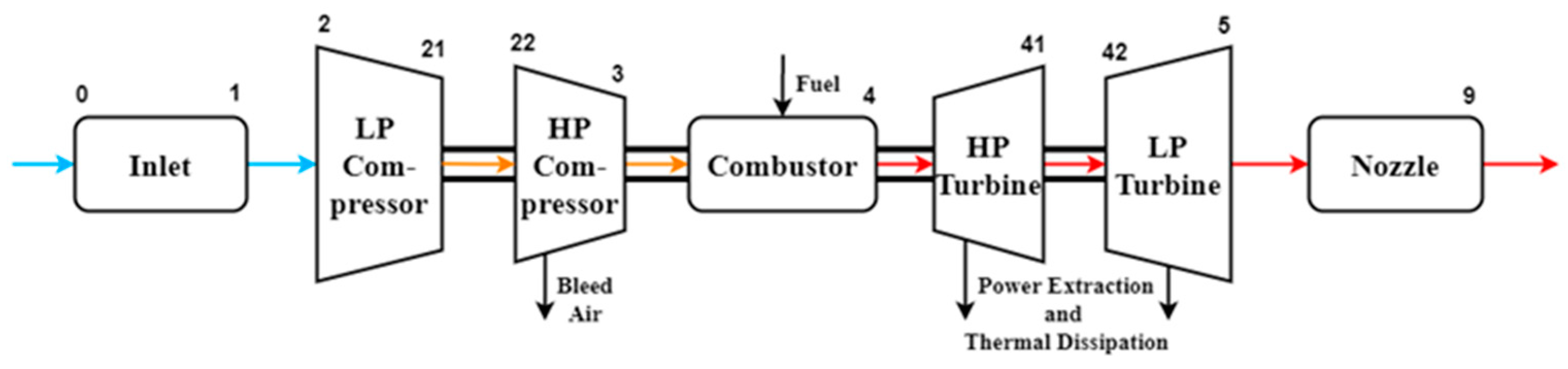
2.1. Engine Architecture

The engine selected for simulation in this study is a typical twin-spool axis flow turbojet engine. Because of its complex overall structure, it has been simplified while retaining components such as the inlet, compressor, combustor, turbine, and nozzle.
The engine is depicted in Figure 1, based on the above engine system structure, as well as the working principles and mass and energy conservation relationships of each component.
Because of the difficulty of establishing an accurate mathematical model, the following assumptions are made without affecting the thermodynamic laws of the engine:
(1)
The gas flow in the engine is treated as one-dimensional flow, and the inlet and outlet airflow parameters of each component are represented by the average value;
(2)
Neglecting the impact of combustion lag;
(3)
Neglecting solid wall heat transfer;
(4)
Neglecting the viscous and inertial forces of gases.

2.2. Component Thermodynamic Model

The component-level model is a mathematical model established based on the structure and working principle of the corresponding component, and the components satisfy the aerodynamic thermodynamic equations, mass conservation equations, energy conservation equations, etc.
(1)
Compressor
The compressor is a component that increases air pressure. The working principles of the low-pressure compressor and the high-pressure compressor are similar, and the thermodynamic equations are:
n c o r = n T / n d T d
W a , c o r = f ( n c o r , β ) η c o r = f ( n c o r , β ) π c o r = f ( n c o r , β )
W a = C W × W a , c o r × p p d × T d T
T o u t = f ( T i n , η , F A R )
N = W a × ( H o u t H i n ) ,
where c o r is the conversion value, β is the auxiliary value, C W is the flow correction coefficient, and F A R is the fuel air ratio.
(2)
Combustor
The combustor is one of the core components of the engine, where fuel and air mix and burn, producing high-temperature and high-pressure gas. The thermodynamic equations are:
H 4 = ( W 3 × H 3 + W f × η b × H u ) / ( W 3 + W f )
W 4 = W 3 + W f
T 4 = f ( H 4 , F A R 4 ) ,
where η b is the combustion efficiency and H u is the fuel calorific value.
(3)
Turbine
The turbine converts the kinetic and thermal energy of the gas into the mechanical energy of the rotor, driving the compressor to rotate. The thermodynamic equations are similar to those of a compressor. The compression process becomes the expansion process, which will not be repeated here.
(4)
Nozzle
The gas continues to expand in the nozzle, converting its remaining heat energy into kinetic energy, generating reverse thrust to propel the aircraft forward. The thermodynamic equations are:
v 9 = 2 × C p × T i n × ( 1 ( p s , 9 p t , i n ) ( k 1 k ) )
W 9 = K m × p t , 9 T t , 9 × A 9 × Q λ
F N = C T × W 9 × ( v 9 v 0 ) + A 9 × ( p s , 9 p s , 0 )
where p s , 9 is the static pressure at the nozzle outlet, K m is the coefficient, Q λ is the flow function, and C T is the thrust correction coefficient.

3. Engine Model with the Variable Mass Approach

The co-working conditions for the components of a twin-spool axis flow turbojet engine during stable operation are gas mass flow balance, pressure balance, power balance, and equal rotational speeds [14,30]. Several approaches exist for solving the dynamic process of the engine. For example, the constant mass flow approach is the classical method, the volume dynamic approach greatly improves the calculation speed, and the variable mass approach proposed by the authors improves accuracy based on rapidity. These three approaches are described below.

3.1. Constant Mass Flow Method

The constant mass flow method [14,31,32] is a fundamental approach in engine dynamic simulation. The co-working conditions of engine components are described by the nonlinear equation system that reflects mass flow balance and energy balance [14]. After giving initial guess values and control variables, the Newton–Raphson method is used to solve the nonlinear equation system to obtain the steady-state operating point of the engine [31]:
f 1 ( n H , n L , π L C , π H C , π H T , π L T ) = W A 22 / W A 21 1 = 0 f 2 ( n H , n L , π L C , π H C , π H T , π L T ) = ( W A 3 + W f ) / W G 4 1 = 0 f 3 ( n H , n L , π L C , π H C , π H T , π L T ) = W G 42 / W G 41 1 = 0 f 4 ( n H , n L , π L C , π H C , π H T , π L T ) = W G 9 / W G 5 1 = 0 f 5 ( n H , n L , π L C , π H C , π H T , π L T ) = η H N H T / N H C 1 = 0 f 6 ( n H , n L , π L C , π H C , π H T , π L T ) = η L N L T / N L C 1 = 0
In the dynamic process, the volume inertia and thermal inertia of the engine are ignored, only meeting the flow balance condition. The last two equations of Formula (12) are replaced by the rotor dynamics equation [10,33]:
d n H d t = ( η H N H T N H C ) / [ n H J H ( π 30 ) 2 ]
d n L d t = ( h L N L T - N L C ) / [ n L J L ( p 30 ) 2 ] ,
where N is the output/input power of the turbine/compressor, and J is the inertia of the shaft rotor.
Through the above equations, the steady-state operating point and the rotor speed at the next time are continuously calculated, and the dynamic simulation of the engine is completed.

3.2. Volume Dynamic Method

The constant mass flow method solves the problem iteratively, which is very time-consuming. However, the volume dynamics method utilizes the volumetric dynamics equation to calculate the pressure ratio of rotating components through integration, replacing the iterative process and greatly improving the speed. Generally, the volume chamber selected using this method is the space between components or the interior of large space components such as combustor and bypass. Taking the combustor as an example, differentiating the time term from the ideal gas state equation [24],
d ( p V m R T ) d t = 0 .
Due to the correlation between p , m and T with time terms, further transformation can lead to
V d p d t R T d m d t m R d T d t = 0 .
The above equation indicates the variation of volume outlet pressure over time, which is influenced by two aspects: the energy storage effect of temperature changes and the mass storage effect of pressure fluctuations. The volume dynamics method only takes the influence of the mass storage effect for simulation:
d p d t = ( W i n W o u t ) R T V .
Multiple volume chambers are selected inside the engine, and the pressure ratios at the next moment are continuously calculated using the volumetric dynamics equation. Then, combined with the rotor dynamics equation, the shaft speed is calculated to complete the simulation.
However, the volume dynamics method ignores the energy storage effect caused by temperature changes. Through subsequent calculations, it is found that the energy storage effect of components cannot be ignored in some cases, and directly ignoring it will decrease accuracy. Therefore, the authors proposed the variable mass method through the thermodynamic equation of the variable mass system, which considers both energy storage and mass storage effects, improving the accuracy.

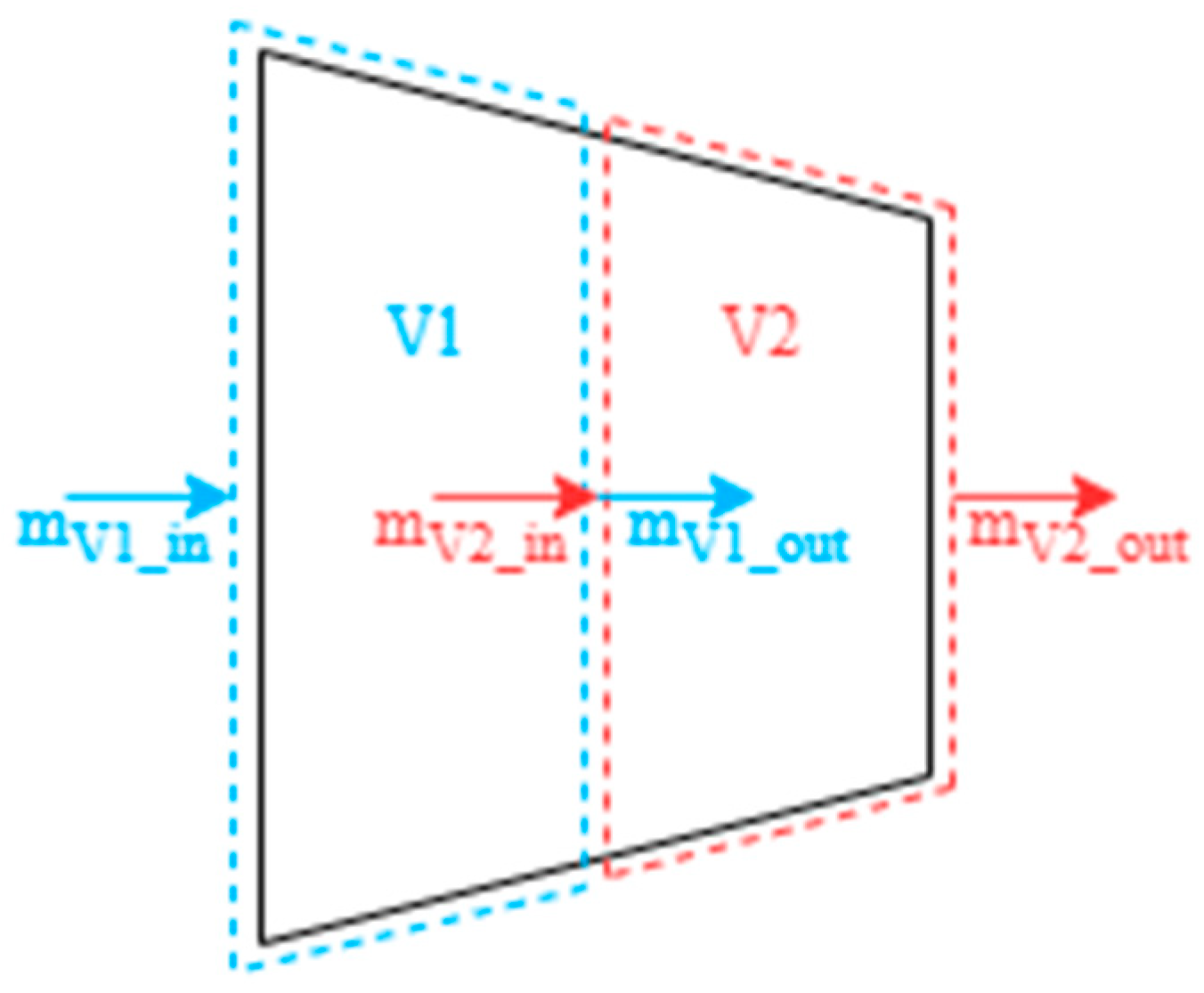
3.3. Variable Mass Method

Compared with the volume dynamic method, the variable mass method establishes control volumes at the selected component inlet and outlet, calculating the component pressure ratio through the imbalance between mass and temperature. The selected control volume consists of four rotating components. The variable mass equations are used in the inlet and outlet, respectively, taking a low-pressure compressor (LPC) as an example (Figure 2). It should be noted that the volume V 1 is bigger than V 2 , otherwise the calculation will not converge.
Based on one-dimensional flow, it can be inferred from the mass conservation equation [29]:
d W d x d x = m t = A d x ρ t .
Because ρ = f   ( p ,   T ) , for ideal gases, there are
( ρ p ) T = 1 R T
( ρ T ) p = p R T 2
d W d x = A [ ( ρ p ) T d p d t + ( ρ T ) p d T d t ] .
Substituting into the above equation yields:
d W d x = A R T [ d p d t p T d T d t ] .
Finally, obtain the equation:
d p d t = R T d W A d x + p T d T d t .
By using the temperature change term and the flow rate change term, the inlet and outlet pressure values for the next moment can be calculated.
The flow and energy rate of the volume are further corrected through the conservation equation of variable mass system: Assume that at time t, the control mass is the sum of the mass m C V in the control volume and the d m i about to enter the control volume. At time t + d t , the mass d m i enters the control volume, and a portion of the mass d m o in the original control volume is pushed out. The control mass remains equal at time t and t + dt, while the formulas for mass and energy balance are as follows.
m C V , t + δ m i = m C V , t + d t + δ m o
δ Q = d E C M + δ N .
In the selected volume chamber, flow accumulation can be calculated by the gas state equation:
Δ W = ( p V R T ) t + d t ( p V R T ) t d t .
The energy accumulation can be calculated by the following formula, and the energy increment for controlling mass within dt time is:
d E C M = d E C V + ( e o δ m o e i δ m i )
δ Q = d E C V + ( e + p v ) o δ m o ( e + p v ) i δ m i + δ N C V ,
where e is the inherent energy of the inflow and outflow fluid itself.
e = u + V 2 2 + g z .
Ignoring the kinetic energy difference and potential energy difference of migration quality, and integrating the time term,
Q C V + h i m i = h o m o + Δ E C V + N C V ,
The control volume and external heat transfer can be ignored and, without axial work, the final result is:
Δ E C V = h i m i h o m o .
Compared to the previous two methods, the variable mass method considers the influence of energy accumulation in the volume chamber and can be expected to have higher accuracy in engine simulation.

4. Results and Discussion

4.1. Verification of Steady-State Simulation Accuracy of Variable Mass Method

The GASTURB 11.0 [34] software has comprehensive data and is widely recognized but cannot capture the instantaneous changes of engine components. Therefore, it is used to verify the accuracy of the variable mass method in the steady-state simulation. The performance parameters of a typical twin-spool axis flow turbojet engine in GASTURB were selected in this article.
The variable mass approach is used to perform a simulation of a certain working process. The Mach number and altitude of the flight mission profile are shown in Figure 3. In addition, the engine regulation law is that the high-pressure shaft speed remains at its maximum value before 125 s and gradually decreases to 90% from 125 s to 185 s. The remaining design parameters are shown in Table 1. The simulation results are shown in Figure 4 and Figure 5.
From Figure 4 and Figure 5, it can be observed that under the conditions of aircraft climb, cruise, and deceleration, except for some points with an error of about 2% in deceleration, the error of all other data is within 1% and the trend of change is consistent. Considering the possible differences in engine bleed, geometric structure, etc., the authors believe that these errors are within an acceptable range and it can be considered that the dynamic simulation of the variable mass approach is accurate.
In addition, the three simulation approaches were also compared. In terms of accuracy, the results of the variable mass approach were very consistent with the other two approaches. In terms of rapidity, the calculation speed of the variable mass method is similar to that of the volume dynamic method and much faster than that of the constant mass flow method. In the dynamic simulation process selected in this article, the time consumption of the three methods is shown in Table 2, and the calculation time of the variable mass approach is only about 1/28 of that of the constant mass flow approach.

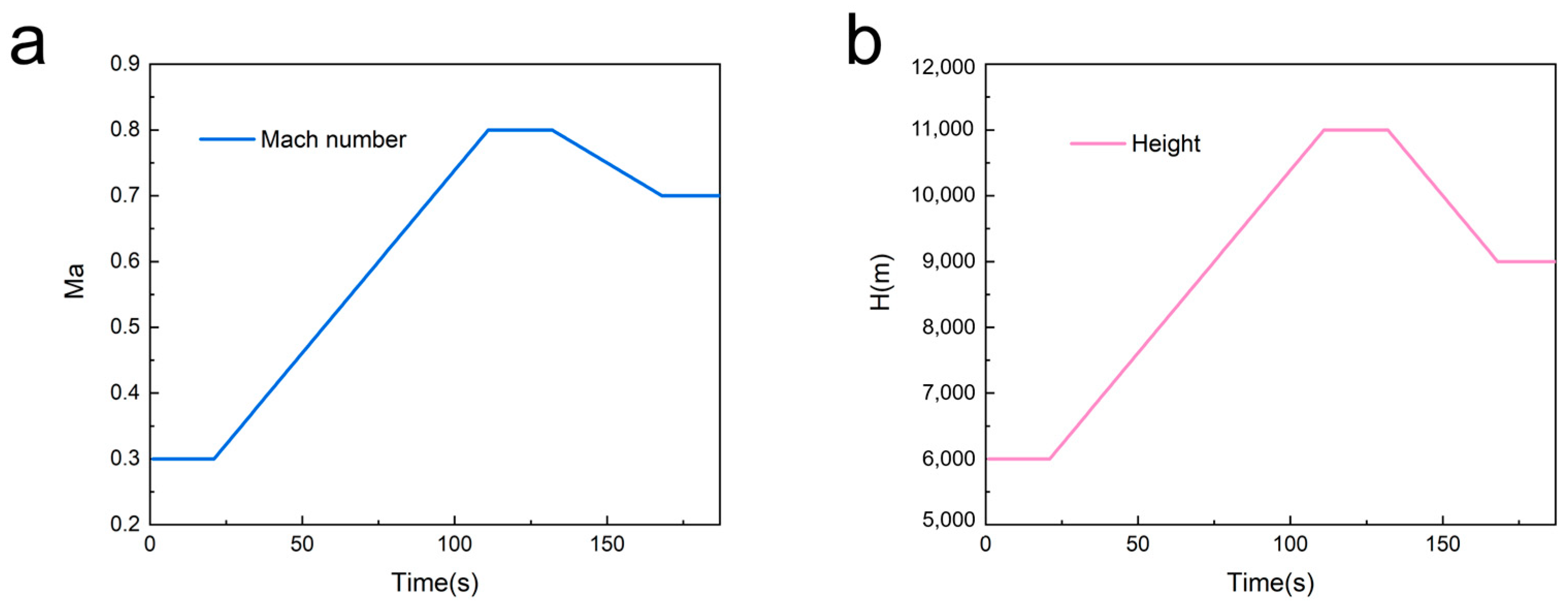
4.2. The Impact of Energy Storage on Instantaneous-Change-State Simulation

Section 3.2 mentioned that the volume dynamic method ignores the energy storage effect. However, the authors found that the influence cannot be ignored when the flight speed changes dramatically, and the variable mass method solves the problem of inaccurate calculation in this situation.
To compare the differences between the variable mass method and the volume dynamic method, two methods were used to simulate two extremely rapid acceleration processes. The design point parameters of the aircraft are shown in Table 1. The flight altitude is 11,000 m, and the Mach number variation of the two processes is shown in Figure 6 and Figure 7, with the high-pressure axis maintaining maximum speed. The first acceleration process lasts for 9 s and the second for 6 s.
Referring to the bench test data of Pratt Whitney J-57 engines with the same configuration, setting the same fuel mass flow rate [35], and taking the outlet flow rate of the high-pressure compressor as an example, the first acceleration process simulation results of the two methods and experimental data are shown in Figure 8.
As can be seen from the figure, compared with the volume dynamic method, the variable mass method has a certain degree of delay in the change of the outlet flow rate of the high-pressure compressor. This result is closer to the experimental results, and the average error of this process has been reduced by 68.3%. During this acceleration process, the maximum time delay reached 0.473 s, accounting for 5.26% of the acceleration process (lasts for 9 s).
At the same time, the energy storage situation inside the high-pressure compressor is shown in Figure 9. It can be seen that when the Mach number changes most dramatically, the energy storage change rate also reaches the maximum value of 96.9 kW, accounting for 0.66% of the rotating shaft power. This power may have a significant impact on the operation of the engine and the phenomenon is more pronounced in larger volume chambers.
The second acceleration process simulation results of the two methods and experimental data are shown in Figure 10.
Similar to the results of the first acceleration process, there is also a certain degree of delay in the change of outlet flow rate and the delay time is longer than that of the first process. The average error of this process has been reduced by 60.6%. During this acceleration process, the maximum time delay reached 0.624 s, accounting for 10.4% of the acceleration process (lasts for 6 s).
From the two acceleration processes, it can be seen that because the variable mass method considers the energy storage effects, there is a time delay in the simulation results of the flow rate, which are closer to the experimental data. This indicates that the variable mass method has higher accuracy than traditional methods. Evidently, the more intense the variation of the Mach number is, the longer the delay time will be.
Under extreme acceleration and deceleration conditions, the time delay and shaft power error resulting from the accumulation of mass and energy in the volume chamber are particularly evident. This can lead to inaccurate fuel supply, insufficient shaft power, and potentially other issues, which in turn affect the instantaneous thrust calculation and power distribution of the engine. The phenomenon can also have an impact on the design of the engine. The consideration of the effects of mass and energy accumulation is of great significance for the simulation and design of engines and relevant subsystems.

5. Conclusions

In conclusion, this work introduces a novel dynamic simulation approach for aircraft engines based on variable mass system thermodynamics. Utilizing this method, three dynamic flight simulations were conducted. The following conclusions were drawn:
(1)
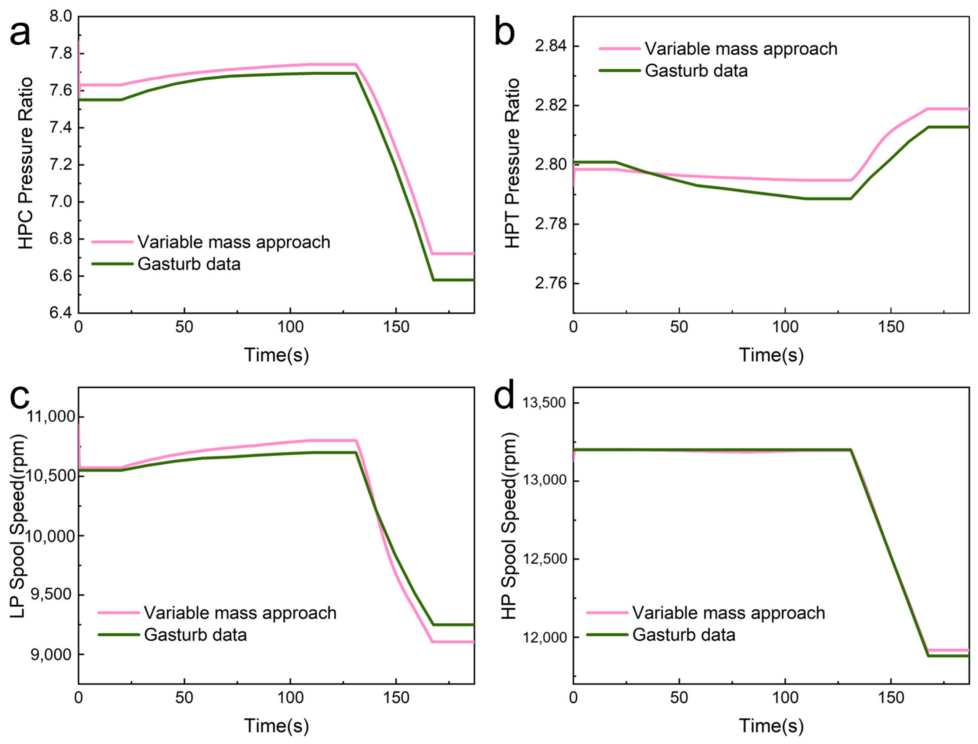
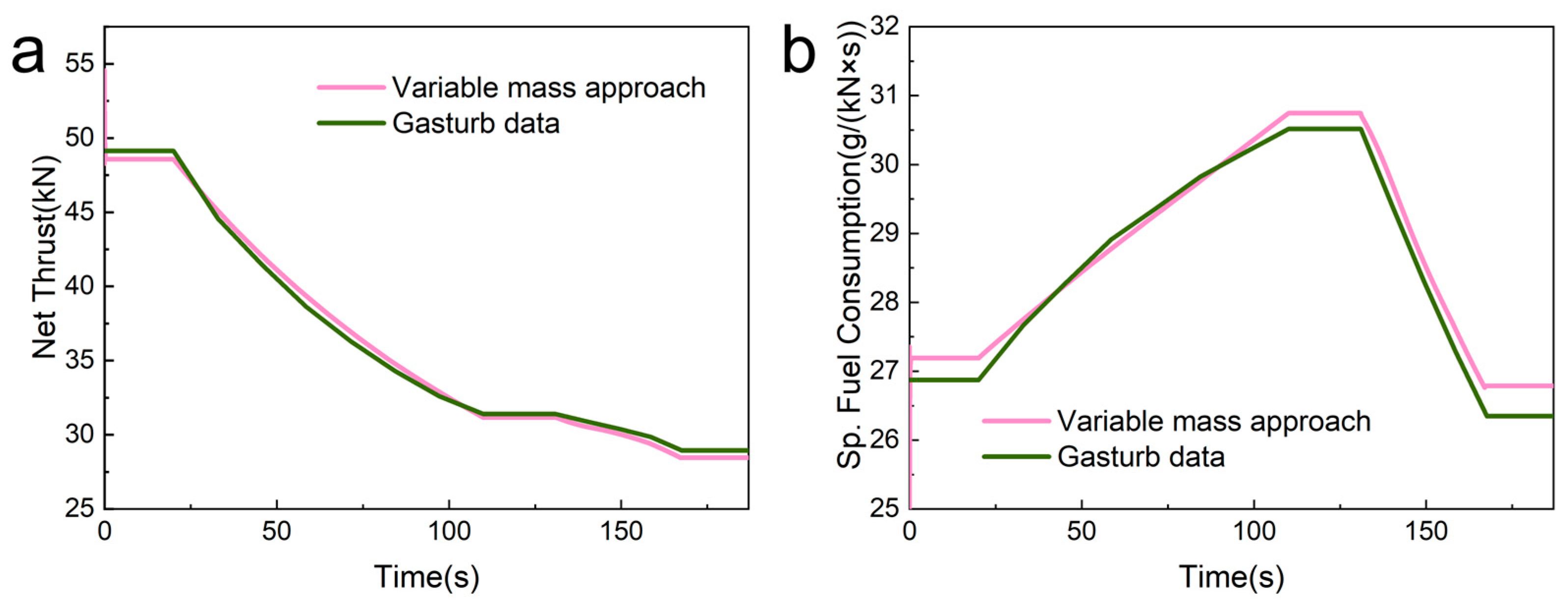
The variable mass method significantly enhances simulation speed, achieving a rate approximately 28 times faster than that of the constant mass flow method based on the Newton–Raphson iterative solution. Moreover, the results are within a reasonable error range when compared with GASTURB data, verifying its accuracy and rapidity.
(2)
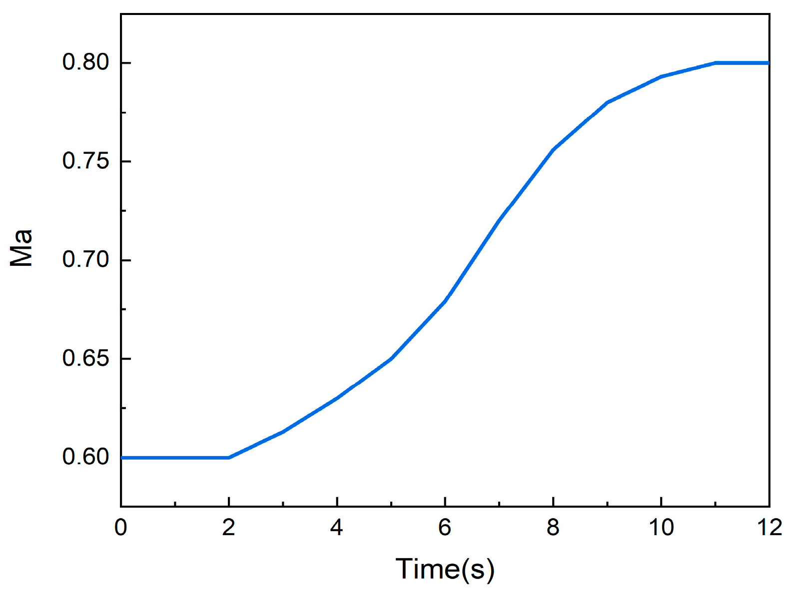
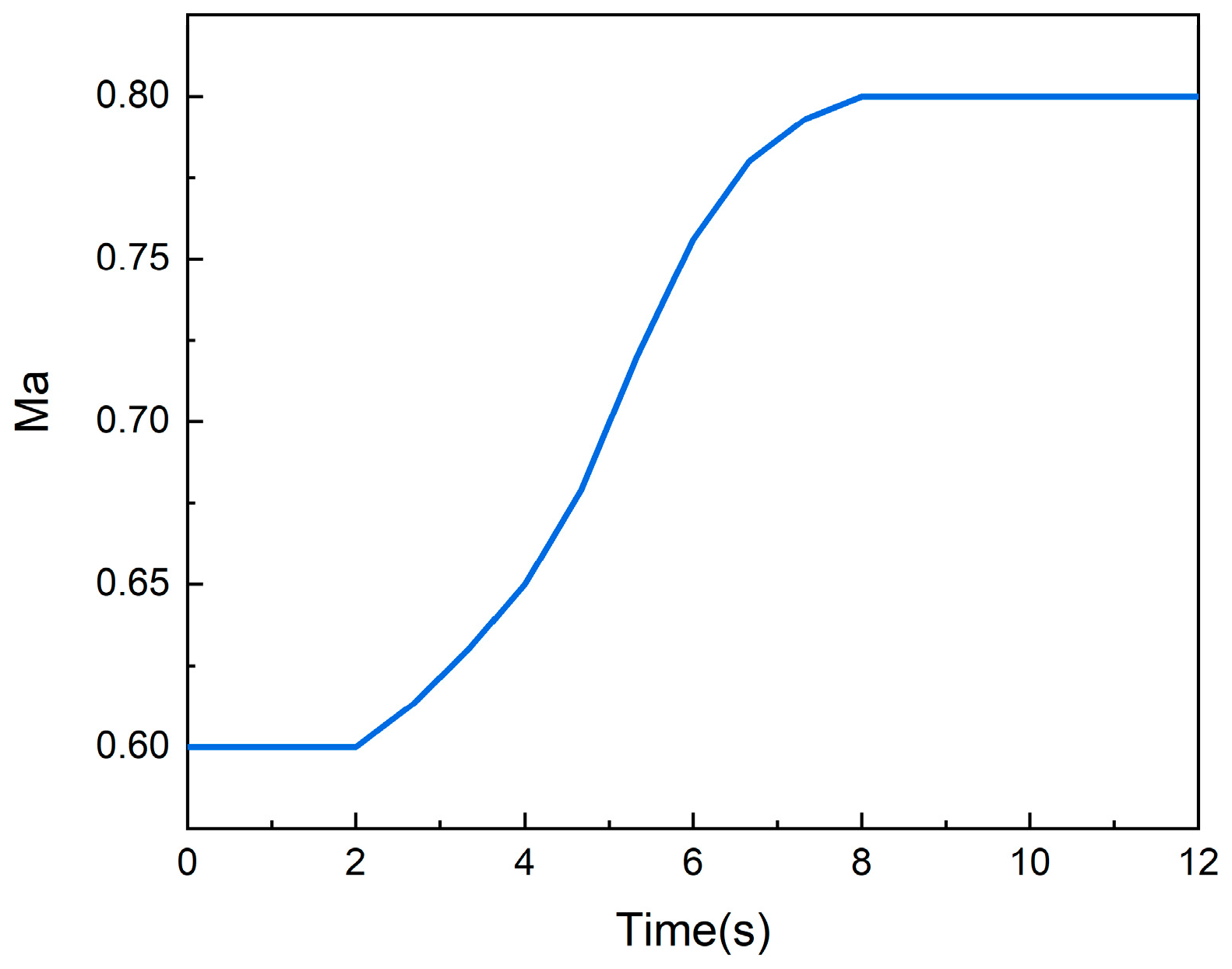
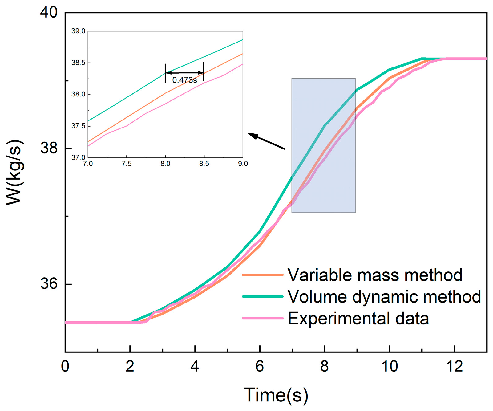
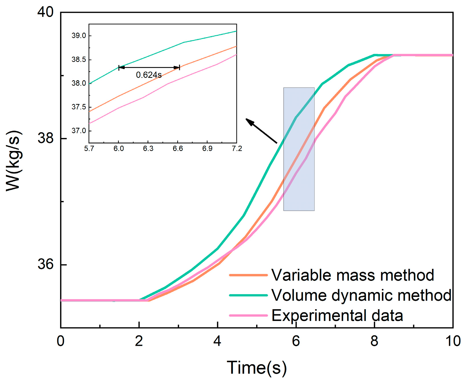
Compared with the traditional volume dynamic method, the variable mass method accounts for the energy storage effect of large-volume components. When there are dramatic changes in flight speed in a short time, the flow and energy storage within the volume chamber can be calculated. In the first acceleration process simulated in this article, the average flow error was reduced by 68.3%, and errors of up to 0.473 s in time delay and up to 0.66% in energy were eliminated. In the second acceleration process, the average flow error was reduced by 60.6%, and an error of up to 0.624 s in time delay was eliminated. Both simulation processes of the variable mass method further improved the accuracy of dynamic simulation. The approach is a feasible and innovative method for engine dynamic simulation and is of great significance for the simulation of relevant subsystems.

Author Contributions

Conceptualization, W.L.; methodology, H.D.; software, H.D.; writing—original draft preparation, H.D.; writing—review and editing, H.D. and W.L. All authors have read and agreed to the published version of the manuscript.

Funding

This work was supported by the Fundamental Research Funds for the Central Universities (501XTCX2023146001), the 1912 Project of China (Grant No. 2019-JCJQ-DA-001-108) and the National Science and Technology Major Project (2019-III-0001-0044).

Data Availability Statement

The numerical simulation results of flow and energy simulated by different methods are available from the corresponding authors upon request.

Acknowledgments

We acknowledge the support of the Fundamental Research Funds for the Central Universities and the 1912 Project of China and the National Science and Technology Major Project.

Conflicts of Interest

The authors declare that they have no known competing financial interests or personal relationships that could have appeared to influence the work reported in this paper.

Abbreviations

NomenclatureGreek symbols
CMcontrol mass η efficiency
CVcontrol volume π pressure ratio
h enthalpy ,   J / kg ρ density ,   kg / m 3
J momentum   of   inertia ,   kg / m 2 Subscripts
W mass   flow   rate ,   kg / s
n shaft   speed ,   rpm 1 , 2 , 3 8 component number of the engine
N power, W H P high-pressure
p pressure ,   Pa H P C high-pressure compressor
R gas   constant ,   J / ( kg · K ) H P T high-pressure turbine
t time constant, s L P low-pressure
T temperature, K L P C low-pressure compressor
u internal   energy ,   J / kg L P T low-pressure turbine
v velocity ,   m / s
V volume ,   m 3

References

  1. Evans, A.; Follen, G.; Naiman, C.; Lopez, I. Numerical Propulsion System Simulation’s National Cycle Program. In Proceedings of the 34th AIAA/ASME/SAE/ASEE Joint Propulsion Conference and Exhibit, Cleveland, OH, USA, 13–15 July 1998. [Google Scholar]
  2. DeCastro, J.; Litt, J.; Frederick, D. A modular aero-propulsion system simulation of a large commercial aircraft engine. In Proceedings of the 44th AIAA/ASME/SAE/ASEE Joint Propulsion Conference & Exhibit, Hartford, CT, USA, 21–23 July 2008. [Google Scholar]
  3. Sadaf, M.; Zeb, M.K.; Salamat, S.; Naqvi, M.A. Sensitivity and Design Point Analysis of RD-93 Engine at Static Sea Level using Numerical Propulsion System Simulation. In Proceedings of the 2020 3rd International Conference on Computing, Mathematics and Engineering Technologies (iCoMET), Sukkur, Pakistan, 29–30 January 2020. [Google Scholar]
  4. Otkur, M. Altitude Performance and Fuel Consumption Modelling of Aircraft Piston Engine Rotax 912 S/ULS. J. Adv. Res. Appl. Sci. Eng. Technol. 2021, 23, 18–25. [Google Scholar] [CrossRef]
  5. Aygun, H.; Cilgin, M.E.; Ekmekci, I.; Turan, O. Energy and performance optimization of an adaptive cycle engine for next generation combat aircraft. Energy 2020, 209, 118261. [Google Scholar] [CrossRef]
  6. Huang, C.; Cheng, X. Estimation of aircraft fuel consumption by modeling flight data from avionics systems. J. Air Transp. Manag. 2022, 99, 102181. [Google Scholar] [CrossRef]
  7. Ren, L.-H.; Ye, Z.-F.; Zhao, Y.-P. A modeling method for aero-engine by combining stochastic gradient descent with support vector regression. Aerosp. Sci. Technol. 2020, 99, 105775. [Google Scholar] [CrossRef]
  8. Pang, S.; Li, Q.; Zhang, H. A new online modelling method for aircraft engine state space model. Chin. J. Aeronaut. 2020, 33, 1756–1773. [Google Scholar] [CrossRef]
  9. Chen, Q.; Sheng, H.; Li, J.; Liu, T. Model-Based Improved Advanced Adaptive Performance Recovery Control Method for a Commercial Turbofan Engine. IEEE Trans. Aerosp. Electron. Syst. 2023, 59, 7440–7454. [Google Scholar] [CrossRef]
  10. Chen, J.; Hu, Z.; Wang, J. Aero-Engine Real-Time Models and Their Applications. Math. Probl. Eng. 2021, 2021, 9917523. [Google Scholar] [CrossRef]
  11. Xiang, S.; Qin, Y.; Luo, J.; Pu, H.; Tang, B. Multicellular LSTM-based deep learning model for aero-engine remaining useful life prediction. Reliab. Eng. Syst. Saf. 2021, 216, 107927. [Google Scholar] [CrossRef]
  12. Zhao, K.; Jia, Z.; Jia, F.; Shao, H. Multi-scale integrated deep self-attention network for predicting remaining useful life of aero-engine. Eng. Appl. Artif. Intell. 2023, 120, 105860. [Google Scholar] [CrossRef]
  13. Yildirim Dalkiran, F.; Toraman, M. Predicting thrust of aircraft using artificial neural networks. Aircr. Eng. Aerosp. Technol. 2021, 93, 35–41. [Google Scholar] [CrossRef]
  14. Fawke, A.; Saravanamuttoo, H.I. Digital Computer Methods for Prediction of Gas Turbine Dynamic Response; SAE Transactions; SAE International: Warrendale, PA, USA, 1971; pp. 1805–1813. [Google Scholar]
  15. Yang, Y.; Nikolaidis, T.; Jafari, S.; Pilidis, P. Gas turbine engine transient performance and heat transfer effect modelling: A comprehensive review, research challenges, and exploring the future. Appl. Therm. Eng. 2024, 236, 121523. [Google Scholar] [CrossRef]
  16. Nikolaidis, T.; Li, Z.; Jafari, S. Advanced Constraints Management Strategy for Real-Time Optimization of Gas Turbine Engine Transient Performance. Appl. Sci. 2019, 9, 5333. [Google Scholar] [CrossRef]
  17. Mansouri, H.; Ommi, F. Performance prediction of aircraft gasoline turbocharged engine at high-altitudes. Appl. Therm. Eng. 2019, 156, 587–596. [Google Scholar] [CrossRef]
  18. Liu, Z.; Huang, Y.; Gou, L.; Fan, D. A robust adaptive linear parameter-varying gain-scheduling controller for aeroengines. Aerosp. Sci. Technol. 2023, 138, 108319. [Google Scholar] [CrossRef]
  19. Ma, J.; Chang, J.; Ma, J.; Bao, W.; Yu, D. Mathematical modeling and characteristic analysis for over-under turbine based combined cycle engine. Acta Astronaut. 2018, 148, 141–152. [Google Scholar] [CrossRef]
  20. Sun, B.; Xu, Q.; Chen, Y. Dynamic modeling and simulation of a pressurized system used in flight vehicle. Chin. J. Aeronaut. 2018, 31, 1232–1248. [Google Scholar] [CrossRef]
  21. Jennions, I.; Ali, F.; Miguez, M.E.; Escobar, I.C. Simulation of an aircraft environmental control system. Appl. Therm. Eng. 2020, 172, 114925. [Google Scholar] [CrossRef]
  22. Xi, Z.; Zhang, H.; Chen, M.; Cai, C.; Wang, J. Design of thrust augmentation control schedule during mode transition for turbo-ramjet engine. Aerosp. Sci. Technol. 2023, 138, 108352. [Google Scholar] [CrossRef]
  23. Zheng, Q.; Wang, Y.; Jin, C.; Zhang, H. Aero-engine dynamic model based on an improved compact propulsion system dynamic model. Proc. Inst. Mech. Eng. Part I J. Syst. Control. Eng. 2021, 235, 1036–1045. [Google Scholar] [CrossRef]
  24. Gennady, G.; Kulikov, H.A.T. Dynamic Modelling of Gas Turbine: Identification, Simulation, Condition Monitoring and Optimal Control; Springer: Berlin/Heidelberg, Germany, 2004. [Google Scholar]
  25. Li, Y.; Xuan, Y. Integrated thermal modeling of helicopters. Appl. Therm. Eng. 2019, 154, 458–468. [Google Scholar] [CrossRef]
  26. Hu, Z.; Xuan, Y. Topology optimization of hydrogen-powered aviation hybrid systems via thermal management principles. Int. J. Hydrog. Energy 2024, 58, 1098–1113. [Google Scholar] [CrossRef]
  27. Sun, J.; Hoekstra, J.M.; Ellerbroek, J. OpenAP: An open-source aircraft performance model for air transportation studies and simulations. Aerospace 2020, 7, 104. [Google Scholar] [CrossRef]
  28. Liu, J.; Xu, M.; Guo, W.; Xi, W.; Liu, C.; Sunden, B. Flow and heat transfer mechanism of a regenerative cooling channel mounted with pin-fins using supercritical CO2 as coolant. Int. J. Therm. Sci. 2025, 208, 109425. [Google Scholar] [CrossRef]
  29. Wu, P.; Ma, Y. Thermodynamics of Variable Mass Systems and Applications; Higher Education Press: Beijing, China, 1983. (In Chinese) [Google Scholar]
  30. Luo, X.; Geng, J.; Li, M.; Liu, B.; Wang, L.; Song, Z. Research on Iterative Calculation and Optimization Methods of Aero-engine On-board Model. J. Syst. Simul. 2022, 34, 2649–2658. [Google Scholar]
  31. Wang, W. Development of Control and Simulation Platform for a Certain Type of Turbojet Engine; Nanchang University: Nanchang, China, 2022. (In Chinese) [Google Scholar]
  32. Eriksson, L.; Nielsen, L. Modeling and Control of Engines and Drivelines; John Wiley & Sons: Hoboken, NJ, USA, 2014. [Google Scholar]
  33. Chen, Q.; Huang, J.; Pan, M.; Lu, F. A Novel Real-Time Mechanism Modeling Approach for Turbofan Engine. Energies 2019, 12, 3791. [Google Scholar] [CrossRef]
  34. Jeschke, P.; Koschel, W.; Klumpp, C.; Weintraub, D. Teaching Aero-Engine Performance: From Analytics to Hands-On Exercises Using Gas Turbine Performance Software. J. Eng. Gas Turbines Power 2025, 147, 011015. [Google Scholar] [CrossRef]
  35. Kurzke, J.; Halliwell, I. Engine Model Examples, in Propulsion and Power: An Exploration of Gas Turbine Performance Modeling; Springer International Publishing: Cham, Switzerland, 2018; pp. 147–212. [Google Scholar]
Figure 1. Engine system architecture. (Numbers represent the inlet and outlet of components).
Energies 17 06424 g001
Figure 2. LPC volume chamber.
Energies 17 06424 g002
Figure 3. Mission profile of the aircraft: (a) Mach number, (b) Height.
Energies 17 06424 g003
Figure 4. Results of rotating components and shafts: (a) HPC pressure ratio, (b) HPT pressure ratio, (c) LP spool speed, (d) HP spool speed.
Energies 17 06424 g004
Figure 5. Results of thrust and SFC: (a) Thrust, (b) SFC.
Energies 17 06424 g005
Figure 6. The first Mach number variation curve.
Energies 17 06424 g006
Figure 7. The second Mach number variation curve.
Energies 17 06424 g007
Figure 8. Comparison of HPC outlet flow rates by two methods and experimental data in 9s-process.
Energies 17 06424 g008
Figure 9. Energy change rate inside HPC.
Energies 17 06424 g009
Figure 10. Comparison of HPC outlet flow rates by two methods and experimental data in 6s-process.
Energies 17 06424 g010
Table 1. Designed parameters used to build the engine system.
Designed ParametersValue
High-pressure (HP) spool speed (rpm)13,200
Low-pressure (LP) spool speed (rpm)10,324
Shaft mechanical transmission efficiency0.99
Inlet flow rate (kg/s)99
Inlet total pressure recovery factor0.99
Low-pressure compressor pressure ratio4.000
Low-pressure compressor isentropic efficiency0.85
Total pressure loss between high and low compressors0.98
High-pressure compressor (HPC) pressure ratio7.000
High-pressure compressor isentropic efficiency0.86
Combustor relative pressure loss0.97
Combustion efficiency0.99
Lower heating value of fuel (kJ/kg)43,124
Fuel flow (kg/s)2.3114
High-pressure turbine (HPT) pressure ratio2.806
High-pressure turbine isentropic efficiency0.90
Total pressure loss between high and low turbine0.98
Low-pressure turbine pressure ratio1.658
Low-pressure turbine isentropic efficiency0.91
Total pressure loss between low-pressure turbine and nozzle0.98
Nozzle throat area (m2)0.1671
Nozzle total pressure recovery factor0.98
Nozzle discharge coefficient0.95
Table 2. Three methods for calculating time consumption.
MethodConstant Mass Flow MethodVolume Dynamic MethodVariable Mass
Method
Time (min)1655.85.8
Disclaimer/Publisher’s Note: The statements, opinions and data contained in all publications are solely those of the individual author(s) and contributor(s) and not of MDPI and/or the editor(s). MDPI and/or the editor(s) disclaim responsibility for any injury to people or property resulting from any ideas, methods, instructions or products referred to in the content.

