Article

Sigma Delta Modulation Controller and Associated Cybersecurity Issues with Battery Energy Storage Integrated with PV-Based Microgrid

by
Syeda Afra Saiara
and
Mohd. Hasan Ali
*
Department of Electrical & Computer Engineering, The University of Memphis, Memphis, TN 38111, USA
*
Author to whom correspondence should be addressed.
Energies 2024, 17(24), 6463; https://doi.org/10.3390/en17246463
Submission received: 26 November 2024 / Revised: 11 December 2024 / Accepted: 17 December 2024 / Published: 22 December 2024
(This article belongs to the Section A1: Smart Grids and Microgrids)

Abstract

:
Battery energy storage systems (BESSs) play a crucial role in integrating renewable energy sources into microgrids. However, robust BESS controllers are needed to carry out this function properly. Existing controllers suffer from overshoots and slow convergence issues. Moreover, as electrical grid networks become increasingly connected, the risk of cyberattacks grows, and traditional physics-based anomaly detection methods face challenges such as reliance on predefined models, high computational demands, and limited scalability for complex, large-scale data. To address the limitations of the existing approaches, this paper first proposes a novel sigma-delta modulation (SDM) controller for BESSs in solar photovoltaic (PV)-connected microgrids. The performance of SDM has been compared with those of the proportional–integral (PI) controller and fuzzy logic controller (FLC). Also, this paper proposes an improved ensemble-based method to detect the false data injection (FDI) and denial-of-service (DoS) attacks on the BESS controller. The performance of the proposed detection method has been compared with that of the traditional ensemble-based method. Four PV-connected microgrid systems, namely the solar DC microgrid, grid-connected solar AC microgrid, hybrid AC microgrid with two BESSs, and hybrid AC microgrid with a single BESS, have been considered to show the effectiveness of the proposed control and detection methods. The MATLAB/Simulink-based results show the effectiveness and better performance of the proposed controller and detection methods. Numerical results demonstrate the improved performance of the proposed SDM controller, with a 35% reduction in AC bus voltage error compared to the conventional PI controller and FLC. Similarly, the proposed SAMME AdaBoost detection method achieves superior accuracy with an F1 score of 95%, outperforming the existing ensemble approaches.

Graphical Abstract

1. Introduction

To address the challenges of global climate change, air pollution, resource depletion and energy security, the transition to renewable energy sources is imperative. Renewable energy sources (RESs), including solar and wind, offer several advantages such as sustainability, environmental benefits, and economic opportunities. Microgrids, especially solar-powered microgrids, play a significant role in advancing renewable energy adoption. Solar microgrids are a key component of the shift towards clean energy due to their ability to harness abundant and renewable solar power [1].
While renewable energy sources offer numerous benefits, they also present challenges, particularly due to their intermittent and variable nature. Solar and wind power generation, for instance, depend on weather conditions and time of day, leading to periods of surplus and deficit in energy supply [2]. This variability necessitates solutions for effective energy management and grid stability. Battery energy storage systems (BESSs) play a critical role in integrating renewable energy sources into the power grid. BESSs provide key benefits such as grid stabilization, energy shifting, peak shaving, and decentralized power.
BESS controllers are indispensable in meeting the demands of today’s energy systems, balancing sustainability, reliability, and efficiency across diverse energy environments [3]. Numerous technologies have been used to design such BESS controllers [4]. Traditional controllers for BESSs have demonstrated significant benefits in applications such as peak shaving, load leveling, frequency regulation, and voltage support. In 2020, a centralized robust H∞ mixed-sensitivity loop shaping controller was proposed to stabilize a standalone PV-BES system [5]. However, the main drawback of this controller was that it tended to be conservative because it was designed to handle the worst-case scenario. Next, an active filter controller was proposed by some researchers to address this problem [6]. However, the active filtering technique requires continuous operation, which can lead to higher energy consumption within the BESS itself. This reduces the net energy available for storage and increases operational costs.
In the following year, 2021, the adaptive nonlinear droop controller [7] and the adaptive terminal sliding mode controller [8] were proposed for PV-BESS system stabilization. However, droop control is less effective in low-inertia systems, such as those dominated by power electronics rather than traditional synchronous machines. BESSs typically have low inertia, which can lead to reduced stability and slower dynamic responses under droop control. Lastly, considering the adaptive terminal sliding mode technology, one of its most significant and well-known drawbacks is the chattering phenomenon, which can lead to the excessive switching of power electronics, causing increased wear and tear, reduced efficiency, and potential damage to battery cells.
Keeping these drawbacks in mind, in 2022, an advanced multi-stage fractional order proportional integral derivative (FOPID) control technology [9] was introduced to stabilize the PV-BESS system. Nonetheless, the additional computational complexity brought about latency in the control loop, potentially affecting the system’s response time, which is critical in fast-reacting applications like BESS. In another paper, a promising model predictive control (MPC) technology [10] was developed to mitigate the PV-BESS stabilization problem. However, the performance of the MPC technology heavily depends on accuracy of the dynamic model of the BESS. As the BESS ages or operates under varying conditions, its dynamics may change, requiring frequent model updates or re-identification. This need for ongoing model maintenance adds complexity and cost to the system.
The fuzzy control [11] technique was introduced in 2023 to stabilize the PV-BESS system. However, fuzzy controllers are generally reactive and do not inherently incorporate predictive capabilities. In BESS applications, where future load and generation patterns are important for optimal energy management, this can be a significant limitation. Finally, neural network (NN) [12]-based controllers were suggested to solve this problem. However, NNs are often considered “black boxes” because it is difficult to understand how they make decisions. This lack of transparency makes it challenging to diagnose issues, explain the controller’s behavior, or gain insights into the underlying system dynamics, which can be problematic in critical applications like energy storage.
As the complexity of power systems increases with higher RES penetration, there is a growing need for novel control methodologies that can address the multifaceted challenges of modern energy storage. These challenges include handling rapid fluctuations in energy generation, ensuring seamless integration with other grid components, and maintaining system reliability under diverse operating conditions [13]. Therefore, there is still the need to design a BESS controller using new technology that can address the modern grid challenges, and that is why this work has been dedicated to finding a new BESS controller design.
It is noteworthy that cybersecurity issues in power grids are becoming increasingly critical due to the growing reliance on digital technologies, automation, and remote control systems [14]. Traditional power grids were built with operational efficiency in mind, not cybersecurity, which makes them particularly vulnerable to cyberattacks [15]. Attacks on the supervisory control and data acquisition (SCADA) systems, which monitor and control power distribution, are of significant concern [16]. These systems can be manipulated to disrupt operations, leading to widespread blackouts or physical damage to the grid.
As already mentioned, BESSs play a crucial role in stabilizing the grid, but a BESS controller serves as a critical attack point in the system, as it manages and monitors battery operations, including the charge and discharge cycles [17]. By targeting the BESS controller, attackers can manipulate or disrupt these control functions, leading to compromised system performance, safety issues, and potentially severe operational failures. In the context of grid-connected BESS, one major issue is the potential manipulation of data between the grid and the storage system. A cyberattack could interfere with communication protocols, causing improper charging or discharging schedules, which could destabilize the grid and lead to power outages [18]. A cyberattack, if left undetected, at one layer of the system would consequently negatively affect other layers. Compromised BESSs may behave in violation of the mechanical and electrical safety protocols. Therefore, it is crucial to consider all the layers while developing the defense strategy of a BESS, including the possibility of integrity attacks, such as false data injection (FDI) attacks, and availability attacks such as denial-of-service (DoS) attacks, which have a significant impact on the grid.
Regarding the attack detection methods, the model-free convolutional neural network (CNN)- and long-short term memory (LSTM)-based approaches have been suggested in [19]. However, LSTMs are slow when training large datasets and thus not a good option for power system applications, while CNNs have the problem of overfitting. Another work [20] proposed a watermarking mechanism at the inverter side to detect FDI attacks. Nevertheless, this process involves adding a watermark signal to all the data, which is both expensive and time-consuming. All these works have considered the inverter side of the PV system. Not much research has been conducted on a PV system integrated with a BESS.
Studies such as [21] have used chi-squared detectors to detect FDI attacks on a PV-integrated BESS. This technique allowed the authors to detect attacks of magnitude 20 mV. In contrast, the paper in [22] focused on identifying intricate attacks that were tough to identify in a noisy system, since large-magnitude attacks may be easily detected by the system operator using bad data detectors. Here, the authors applied an extended Kalman filter (EKF) and a cumulative sum (CUSUM) algorithm in their work, allowing them to detect attacks of as small as 1 mV. However, to this end, all the attacks were considered on the state-of-charge (SOC) estimations of the battery management system (BMS) or sensor-measured values. Another machine learning (ML)-inspired method, the artificial neural network (ANN)-based anomaly detection technique, was proposed to detect attacks on a PV-integrated BESS in [23]. However, one limitation of this technique is that it exhibits a high false positive rate when detecting FDI attacks on battery SOC estimation. Therefore, an ensemble-based learning detection method has been proposed in [24].
Based on the above literature review, it appears that various controllers have been developed to address the rapid charging and discharging of BESSs in response to the intermittent nature of renewable energy sources, but they often suffer from issues like overshoots, oscillations, and slow settling times. Moreover, as electrical grid networks become increasingly connected, the risk of cyberattacks grows, and traditional physics-based anomaly detection methods face challenges such as reliance on predefined models, high computational demands, and limited scalability for complex, large-scale data. To address these limitations, this paper first introduces a novel sigma-delta modulation (SDM) controller for BESSs in microgrids, offering high-resolution capabilities, low bandwidth, and superior noise-shaping features that outperform the existing technologies in this application. The SDM controller achieves precise control of voltage and power fluctuations in a BESS by leveraging high-resolution modulation, rapid sampling, and feedback mechanisms, ensuring enhanced stability, reduced harmonics, and seamless integration within hybrid microgrids. It dynamically adjusts the duty cycle of the buck–boost converter based on voltage and current feedback, enabling efficient energy regulation and load balancing. The performance of the proposed SDM controller has been compared with that of the fuzzy logic controller (FLC) and the proportion–integral (PI) controller.
In addition, this work proposes a machine learning-based ensemble learning approach, including the enhanced stagewise additive modeling using a multi-class exponential loss function (SAMME) AdaBoost method, to efficiently detect critical cyberattacks like FDI and DoS on BESS controllers in microgrid systems. The SAMME AdaBoost algorithm is superior for cyberattack detection in multiclass problems as it extends AdaBoost to handle multiple classes directly, with faster classifier weight updates and improved accuracy, enabling more effective differentiation between diverse attack types compared to the traditional one-class AdaBoost system. The proposed SAMME method is compared with that of the ensemble-based detection method.
In this work, extensive simulations are conducted through MATLAB/Simulink R2023b software to validate the efficacy of the proposed SDM controller and SAMME detection method. Four microgrid systems under varying solar irradiance and wind speed conditions are considered. A novel index-based performance comparison among BESS controllers is made.
In summary, the novelty and major contribution of this paper stand on the following facts:
(i)
This work develops a fast and sophisticated SDM controller for the optimal charging and discharging of a BESS to maintain constant load power and load voltage despite the intermittent tendency of the grid-connected PV system;
(ii)
The proposed SDM controller has been designed for four PV-based microgrid systems;
(iii)
An improved ensemble-based method (SAMME AdaBoost) for cyberattack detection on the BESS controller has been developed.
This paper is organized as follows: Section 2 describes the problem statement by showing the impact of the irradiance and wind speed variations on the generated power and voltage. The impact of cyberattacks (FDI and DoS) on the BESS controller is also shown in this section. Section 3 describes the microgrid systems that have been designed in MATLAB/Simulink for this work. Section 4 describes the detailed structure of the SDM controller as well as the conventional controllers. Section 5 is about the simulation result and discussion. Section 6 describes the improved ensemble learning (SAMME AdaBoost)-based cyberattack detection technology that has been developed in this work to ensure the cybersecurity of BESS-incorporated microgrid systems. Section 7 provides the conclusion for this work and describes the future scope of the paper.

2. Problem Statement

As previously mentioned, BESSs are an extremely important component in PV-based microgrids. The BESS, along with its controller, helps to ensure voltage stability, system efficiency, and the safety of the microgrid [25]. Also, as cyber threats become increasingly sophisticated, cyberattack detection strategies are imperative to safeguard microgrid systems. Prioritizing cybersecurity alongside technological advancements ensures the secure and resilient operation of microgrids, contributing to a more sustainable and reliable energy future [26].
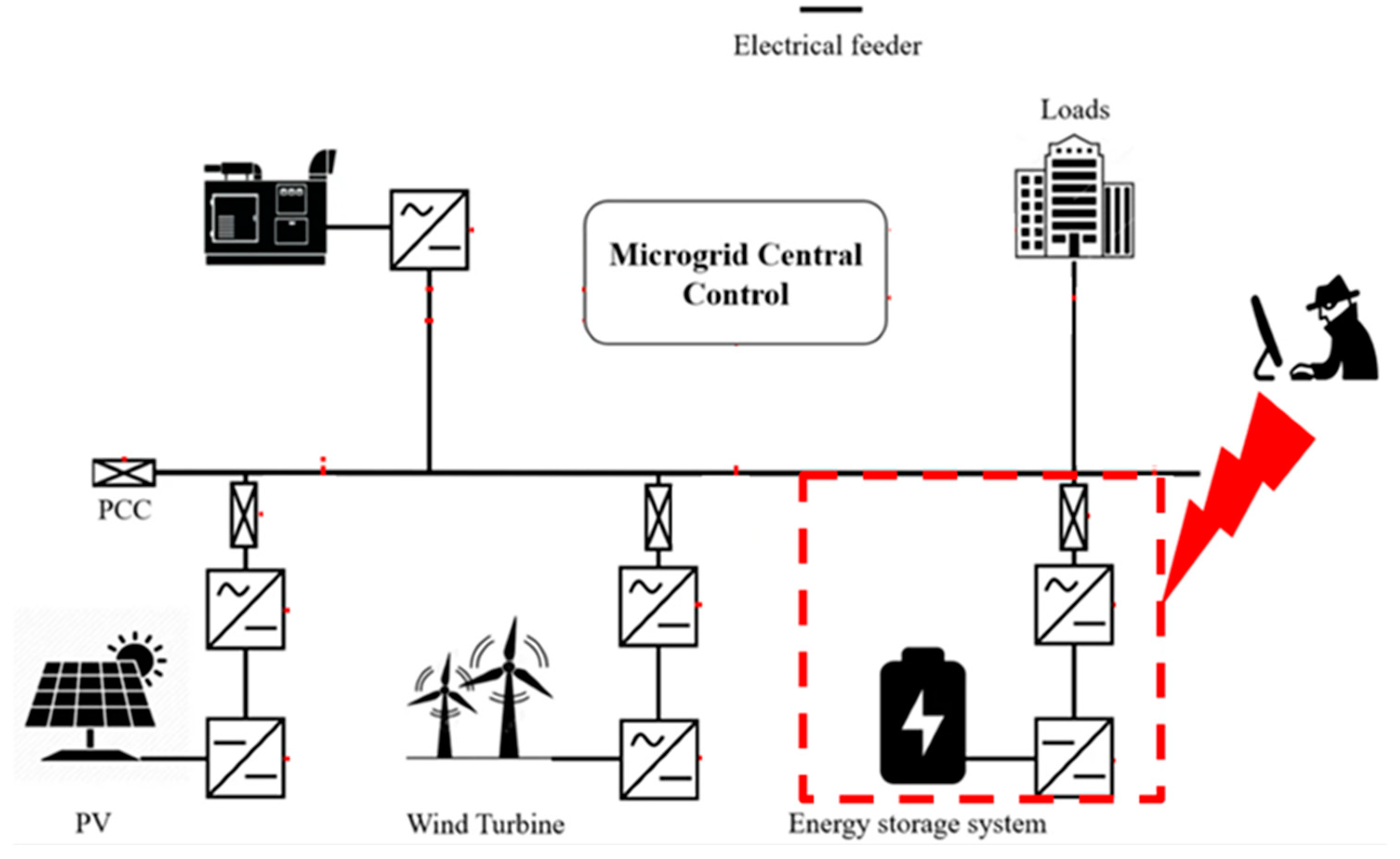
To understand the importance of a BESS controller and how cybersecurity is connected to the controller, let us consider the hybrid AC microgrid system shown in Figure 1. The system consists of three energy sources, including a solar photovoltaic (PV) generator, a wind turbine generator, and a conventional permanent magnet synchronous generator (PMSG) [27]. Two BESSs are attached to the PV generation point and wind turbine generation point. The BESSs are included to charge/discharge and manage power fluctuations.
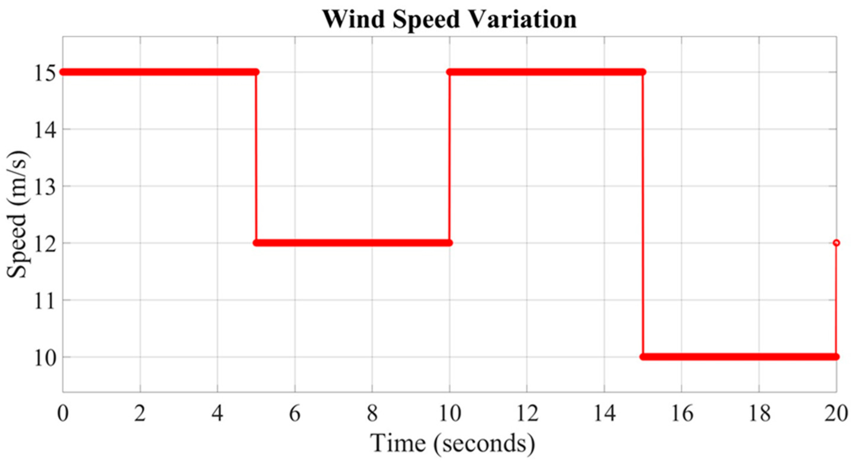
Figure 2 and Figure 3 show the wind speed and solar irradiance variations [28], respectively, that have been considered for the microgrid system in Figure 1. As the irradiation of the PV system and the wind turbine speed fluctuate, the AC bus voltage experiences variations. These fluctuations can lead to unstable voltage levels, which may affect the quality of power delivered to consumers. At the consumer end, this can result in equipment malfunction, decreased efficiency, and potential damage to sensitive electrical devices. The AC bus voltage profile is shown in Figure 4.
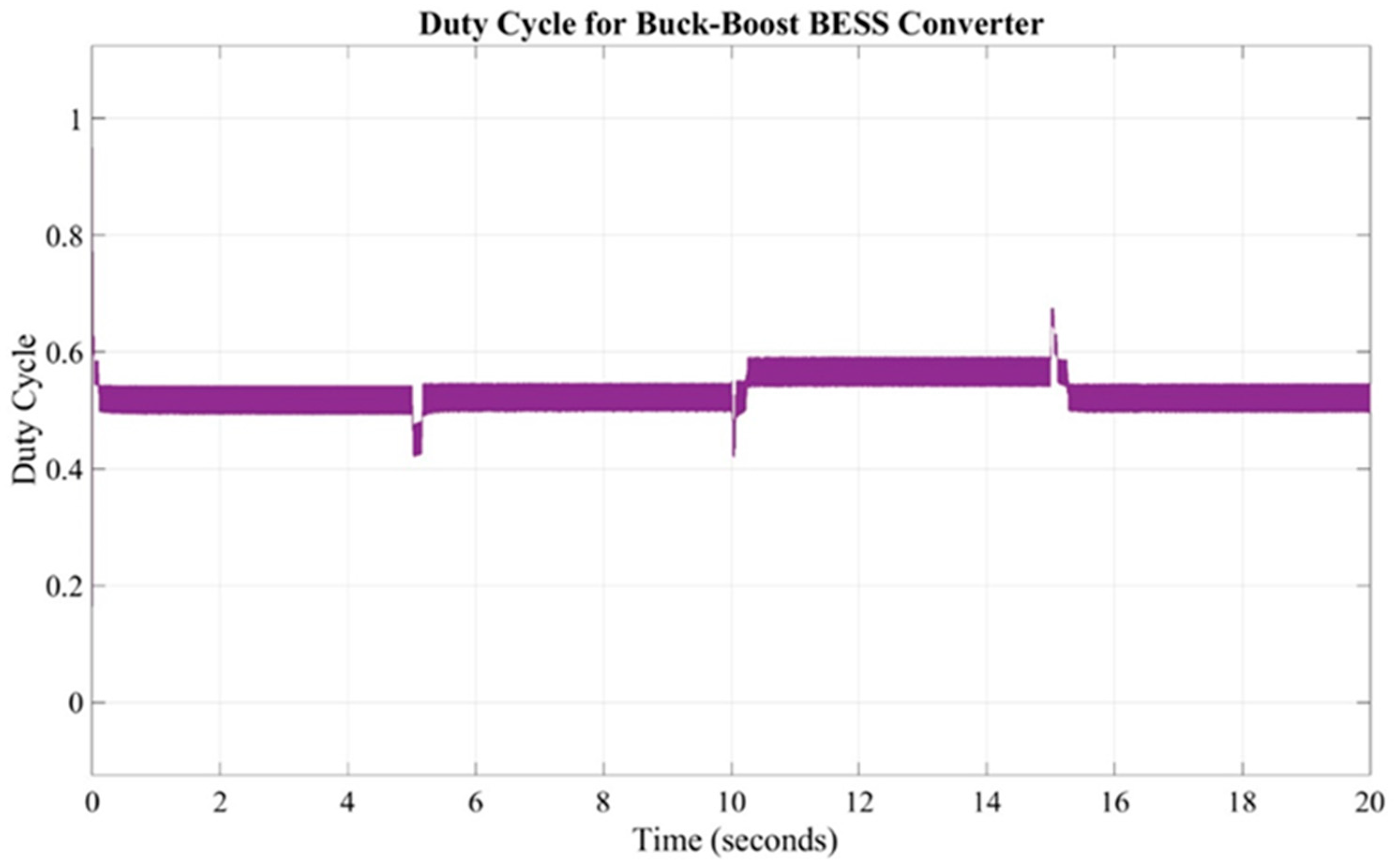
Figure 5 examines the effect of varying solar irradiance (Figure 2) on the duty cycle of a DC/DC BESS converter connected to a PV system. To simulate realistic changes in solar irradiance, the irradiance levels are modified at the following specific time intervals: 5, 10, 15, and 20 s. Each change in irradiance triggers an adaptive response in the DC/DC converter, adjusting its duty cycle to maintain optimal power transfer. The corresponding duty cycle adjustments help to stabilize the PV system output despite the fluctuating irradiance. It is evident that at t = 10 s, the duty cycle increases from 0.5 to operate the BESS in charging mode. When the irradiance comes down to the nominal level at t = 15 s, the duty cycle drops down to 0.5. Thus, Figure 5 illustrates this relationship, showing how the duty cycle dynamically responds to changes in irradiance, ensuring efficient operation across variable conditions.
A cyberattack on a hybrid energy system can have severe consequences, affecting system stability, safety, reliability, and economic performance. These systems rely on digital controls, communication networks, and supervisory systems like SCADA, making them vulnerable to cyber threats, as shown in Figure 6. A BESS is essential for frequency regulation and energy balancing. A cyberattack targeting the BESS controller could cause it to either overcharge, discharge at inappropriate times, or become unresponsive [29]. If a cyberattack manipulates the BESS’s charge/discharge cycles, it could cause energy imbalances within the hybrid system. For example, if the BESS discharges too early or fails to discharge during periods of high demand, it could lead to load mismatch, where the energy supply does not meet the demand, causing brownouts or blackouts.
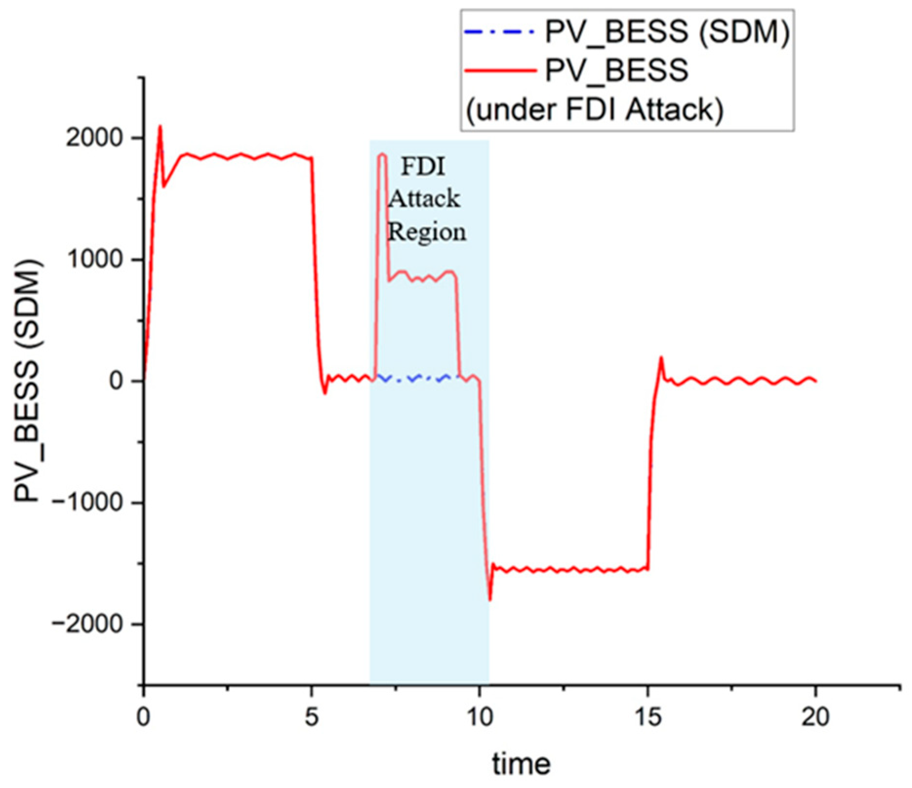
In Figure 7, the impact of an FDI attack on the PV-BESS power is shown. The FDI attack was implemented on the SDM controller of the PV-BESS portion of the hybrid microgrid system (Figure 1). At 5 s and 10 s, the battery was supposed to be in nominal condition, i.e., the BESS power was supposed to be 0. However, the FDI attack occurred between 7.5 s and 10 s. During this time, the reference set point of the SDM controller was made higher than the required value. As a result, the battery discharged during this time, whereas it was supposed to be in nominal condition.
In a second scenario, another type of cyberattack, i.e., the DoS attack, was implemented on the system. To implement this attack, a delay block was placed after the output of the SDM controller. This attack was implemented first from 6 to 8 s and, again, between 16 and 18 s. The first DoS attack (t = 6–8 s) was implemented on the PV-BESS controller. The adverse impact of the attack on the PV-BESS power profile is shown in Figure 8. Initially, the PV-BESS power stabilizes at a high positive level, indicating the efficient discharge of power from the BESS. However, around 6 s, a DoS attack begins, marked by rapid fluctuations around the nominal line (0 watts). These high-frequency oscillations signify power instability, potentially causing inefficiencies and stress on the system components.
Since the solar irradiance change and wind speed variations cause voltage and power fluctuations, and cyberattacks impact the functionality of BESS controller, the development of a new controller and new detection method are needed for the PV-based microgrid systems. This is the motivation behind this work.

3. Description of Microgrid Systems Including PV

In this work, four microgrid systems have been considered for the performance analysis of the proposed BESS controller and the associated attack detection method. One of the four microgrid systems has already been described in Figure 1 of Section 2. The other three systems are described below.

3.1. Solar DC Microgrid System

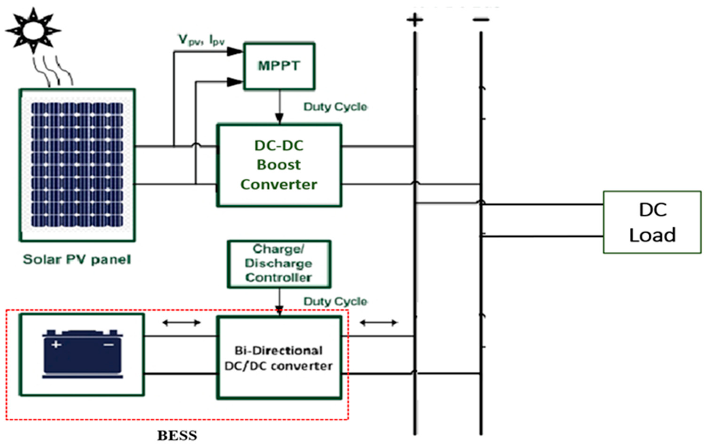
A solar microgrid system (as shown in Figure 9) is a localized power generation setup that primarily relies on solar energy to meet the electrical needs of a small community, building, or even an individual home [30]. It includes key components such as a PV module, Maximum Power Point Tracking (MPPT), DC/DC converter, energy storage system, and loads. MPPT algorithms ensure the PV system operates at maximum efficiency, adjusting the DC/DC converter’s output. For our work, the Perturb and Observe (P&O) algorithm was used for MPP tracking. The system was simulated dynamically, with real-time variations in irradiance and battery storage states, making it ideal for analyzing the microgrid’s performance under different scenarios. The parameters of the different components that were used in this design are given in Appendix A, Table A1, Table A2, Table A3 and Table A4.

3.2. Grid-Connected Solar AC Microgrid System

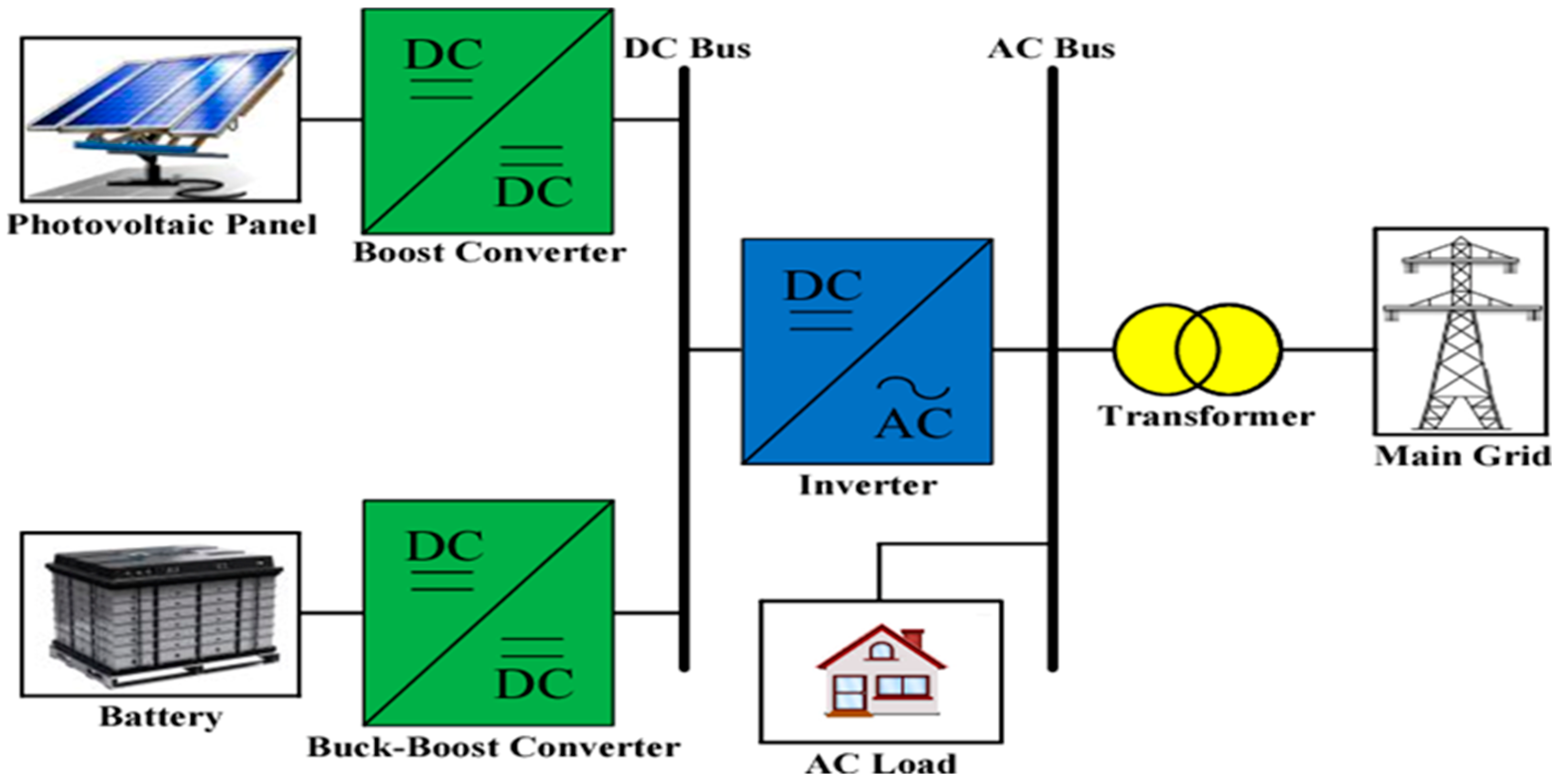
A grid-connected solar AC microgrid system operates by integrating solar energy with the utility grid, allowing for an energy exchange between the microgrid and the main grid [31]. Figure 10 shows the structure of the grid-connected solar AC microgrid system. In addition to the components described above for the solar DC microgrid, there are two additional components in this system such as a DC/AC inverter and filter. This DC/AC inverter converts the DC output of the solar cells and supplies it to the AC grid. We have used the dq transformation technique to synchronize the AC power with the grid frequency and voltage. The output of the inverter suffers from a high level of distortion. So, we used LC filters to smooth out the inverter’s output power. The parameters of the filter are given in Appendix A, Table A5.

3.3. Hybrid AC Microgrid with a Single BESS

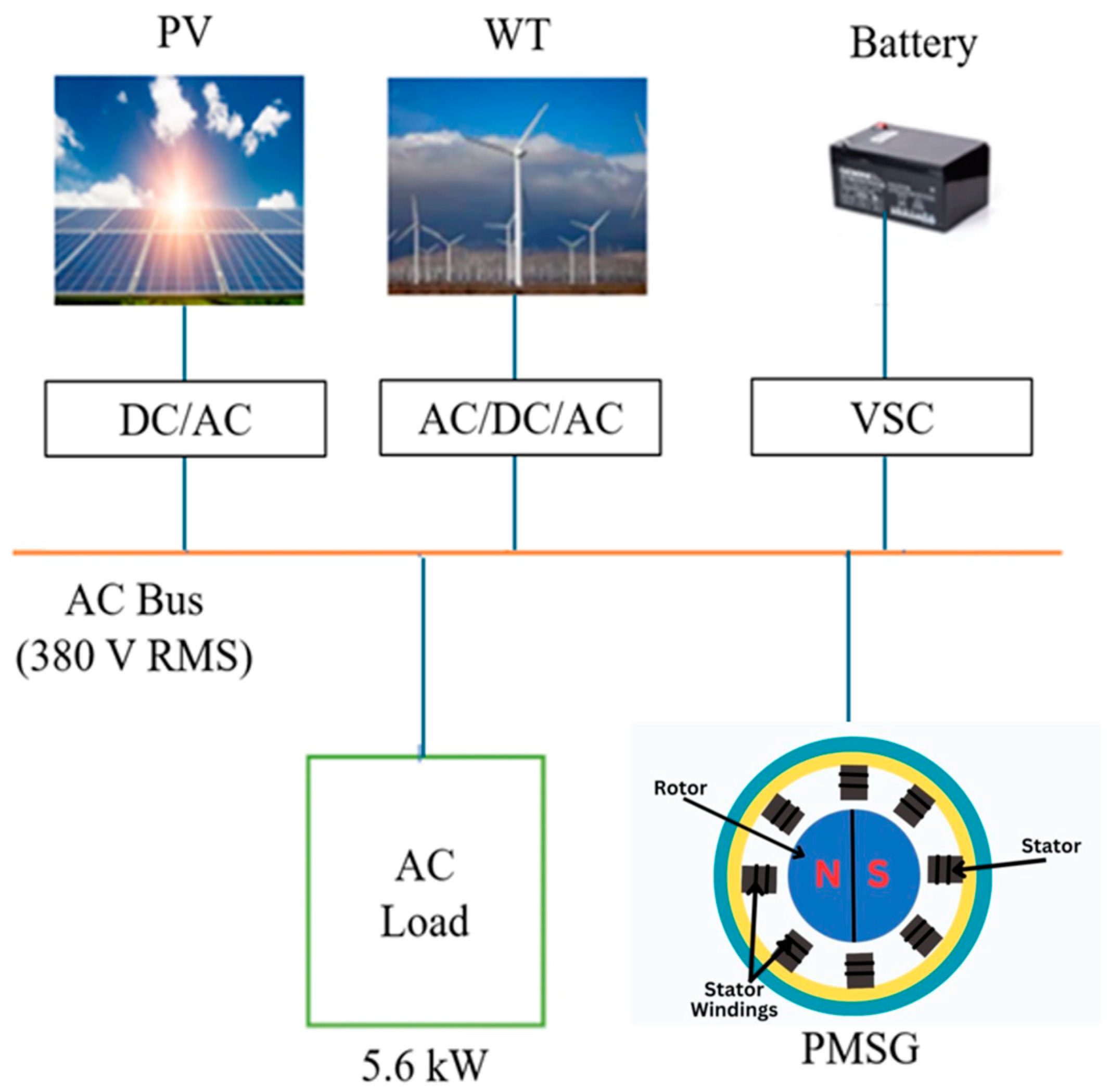
Figure 11 depicts a hybrid AC microgrid with a single BESS and integrates multiple energy sources, such as solar PV, wind turbine generator, and a conventional PMSG [32]. The BESS plays a crucial role in smoothing out the intermittent power generation from renewable sources by storing excess energy during periods of low demand and releasing it when demand is high or when renewable output fluctuates. The solar irradiation and wind speed variations considered for this system are the same as shown in Figure 2 and Figure 3 in Section 2.

4. Proposed Sigma-Delta-Based Control Design for the BESS

Sigma-delta modulation (SDM) is a very popular method to convert an analog signal to a digital signal [33]. The method is derived from delta modulation where the difference between samples is encoded into binary symbols. The term “sigma-delta” reflects the controller’s core functionality, where “sigma” represents integration and “delta” signifies the difference. The controller works by accumulating the difference between the desired signal and the actual value (the error) over time. It then uses a quantization technique to minimize this error, adjusting the output to closely follow the desired signal trajectory.
A sigma-delta controller for controlling the buck–boost operation of a BESS in a microgrid enables precise and stable energy flow between the battery and the grid. By utilizing oversampling, the sigma-delta modulation converts the continuous error signal into a dense pulse stream. This pulse stream controls the duty cycle of the buck–boost converter, dynamically adjusting for charge and discharge modes based on the power demands and grid conditions. In a microgrid, where multiple sources like PV and wind contribute fluctuating power, the sigma-delta controller ensures smooth and responsive voltage regulation, supporting stable and reliable energy exchange between the BESS and the grid. The proposed architecture of the sigma-delta controller used in this thesis is shown below in Figure 12.
The main components in a sigma-delta controller for a BESS and the role each plays in the control process are as follows:
i.
Error Detector
  • Role: Measures the difference between the target (desired) voltage/current and the actual voltage/current from the battery.
  • Function: Generates an error signal, guiding the control adjustments needed for the stable charging or discharging of the battery.
ii.
Integrator
  • Role: Accumulates the error signal over time to create a smoother, slowly varying control signal.
  • Function: Reduces noise sensitivity and smooths out fluctuations, ensuring the system responds based on overall trends rather than short-term disturbances.
iii.
Feedback Loop
  • Role: Provides continuous feedback to the integrator and error detector, adjusting the control dynamically.
  • Function: Helps maintain stability by enabling the controller to adapt to changes in load demand or the battery’s state of charge.
iv.
Comparator
  • Role: Compares the integrated error signal to a reference level or threshold.
  • Function: Produces three outputs (−1, 0, or 1) based on the comparison, which serves as the switching decision (ON/OFF) for the converter’s MOSFET (Metal Oxide Semiconductor Field Effect Transistor), thereby modulating the power flow.
v.
Quantizer
  • Role: Converts the comparator’s analog input into a high-frequency digital pulse stream, as well as operates the sigma-delta controller at a high frequency, much higher than the converter’s switching frequency.
  • Function: Defines the duty cycle in response to the integrator and comparator outputs, enabling precise high-frequency switching for optimal power regulation, as well as allows the oversampling of the input signal, enhancing control precision and responsiveness by providing finer adjustments in duty cycle.
  • Sigma-Delta Controller Input–Output Parameter
The main input parameter of the controller is load power (Pref), from which other reference parameters like bus voltage and load current are calculated as shown in (1) and (2).
V r e f = P r e f × R l o a d
I r e f = V r e f R l o a d
where V r e f is the reference voltage, R l o a d is the load resistance, and I r e f is the reference current.
The output parameter of the sigma-delta controller is the duty cycle D (0 < D < 1) of the two MOSFETs (that control the charging and discharging of BESS), which comes from the comparator output after quantizing through a high-frequency clock cycle.
If D > 0.5, it works in boost mode (discharging), and if D < 0.5, the controller works in buck mode (charging mode).
The controller design parameters for all four microgrids (shown in Figure 1, Figure 9, Figure 10 and Figure 11) are summarized below in Table 1, Table 2, Table 3 and Table 4. These parameters were determined through trial-and-error methods in order to obtain the best performance.
In this work, the performance of the proposed SDM controller has been compared with that of the existing proportional–integral (PI) and fuzzy logic controllers. The existing PI and fuzzy logic controllers are explained below.

4.1. Two-Stage Proportional–Integral (PI) Controller

A two-stage PI controller for a BESS is designed to manage the charging and discharging processes effectively while maintaining system stability and ensuring efficient operation [34]. The two-stage approach typically involves separate control loops to handle the different aspects of power management, such as voltage regulation and current control. Figure 13 shows the control structure of the battery charge controller. The Pref value is calculated for the nominal condition of the system ( P r e f = V 2 R ). At the nominal condition, Ppv = Pdc and the battery remains in standby mode.
However, at times other than the nominal condition, depending on the changing irradiance, the Pdc value changes, as shown in Figure 13. Consequently, an error occurs between the Pref and Pdc values at that time. This error triggers the BESS controller into action, and the PI controller generates an IRef value.
Next, another PI controller compares the value of IRef with the original battery current, Ib, at that moment. This second PI controller minimizes the error between these two current values, generating a duty cycle. The duty cycle is sent to a pulse-width modulation (PWM) generator (fs = 10 kHz) that controls two switches to operate the battery’s charging/discharging mode. Accordingly, the battery is able to store the excess power during irradiance levels higher than the nominal condition, or supply deficit power during times when irradiance levels are lower than the nominal condition. Thus, in this way, the power in the DC bus is always kept constant using the BESS and controller to ensure quality power is delivered to the consumer.
The PI controller design parameters for all four microgrids (shown in Figure 1, Figure 9, Figure 10 and Figure 11) are summarized below in Table 5, Table 6, Table 7 and Table 8. These parameters were determined through trial-and-error methods to obtain the best performance.

4.2. Fuzzy Logic Controller

A fuzzy logic controller operates on the basis of “fuzzy” or approximate reasoning, much like human decision-making [35]. It uses a set of predefined rules and linguistic variables to determine the appropriate control actions. The main steps of a fuzzy controller include the following:
(i)
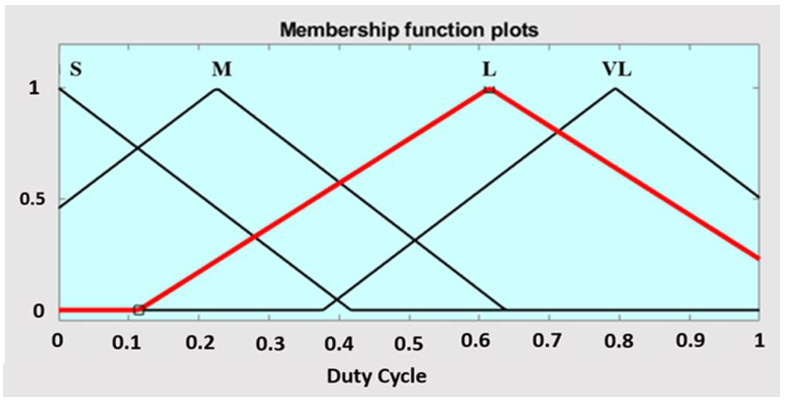
Fuzzification: This process converts precise numerical input values into fuzzy sets. These fuzzy sets represent different levels of these variables. Triangular membership functions (MFs) illustrating linguistic NS (Negative Small), Z (Zero), PS (Positive Small), and PB (Positive Big) for the input (error in power, ΔP) are presented in Figure 14. Similarly, triangular membership functions illustrating variables S (Small), M (Medium), L (Large), and VL (Very Large) for the output (duty cycle, D) are presented in Figure 15. The equation employed for Triangular MFs in determining the grade of membership is as shown in (3) [36]:
μ F ( x ; a , b , c ) = max ( min x a b a , c x c b , 0 )
where the parameters {a, b, c} (where a < b < c) define the three x-coordinates corresponding to the vertices of the triangle.
(ii)
Rule Base: The fuzzy controller stands out for its simplicity, employing a single-input-single-output (SISO) variable design. This use of just one input and one output variable enhances its straightforward structure. The proposed control approach is defined by only five control rules, shown in Table 9, which map the input–output relationships for the controller.
(iii)
Fuzzy Inference and Defuzzification: For the inference mechanism of the fuzzy controller design, Mamdani’s method stands out as widely acknowledged in the literature. Additionally, the center-of-area method, a well-known and straightforward defuzzification technique [37] is employed to ascertain the crisp output value, D (duty cycle) by the following (4):
D = μ C x . x d x μ C x d x
where μ C x d x denotes the area of the region bounded by the curve C.
The fuzzy logic controller design parameters for all four microgrids (shown in Figure 1, Figure 9, Figure 10 and Figure 11) are summarized below in Table 10, Table 11, Table 12 and Table 13. These parameters were determined through trial-and-error methods to obtain the best performance.

5. Simulation Results and Discussion

In this work, the proposed and existing controllers have been implemented on four different microgrid systems, and their performance has been compared. The detailed results are described below.

5.1. Performance of Different Controllers for Solar DC Microgrid System

Figure 16 shows the DC bus power responses for all three controllers. The red line shows the performance of the PI controller. The controller exhibits abrupt overshoots at the places where there are changes in irradiance. So, the next control technology, i.e., the fuzzy logic controller, can solve the overshoot issue that we faced with the PI controller. The performance of the controller is depicted by the green line. However, the main drawback of this controller is that it takes a longer time to settle down and maintain the reference power. Thus, we observe the best performance from the proposed controller, i.e., the SDM controller, which, because of its structure that is specially designed to detect intricate changes in the reference power value, can minimize most fluctuations in the DC bus power. The performance of this controller is depicted by the blue line. In the case of the DC bus voltage (Figure 17), we observe a very similar performance by the three different controllers as was seen in case of the DC bus power.
In the BESS power shown in Figure 18, during the first 5 s, the irradiance level is too low. Thus, the PV generation is below the nominal level. The battery discharges to provide this deficient power to the system. Between 5 s and 10 s, the PV panels operate in the nominal condition. So, the battery just remains in standby mode. From 10 to 15 s, the power generated from the solar cells is higher than the nominal level. Thus, the battery charges to absorb this excess power to maintain constant bus power. In the last 5 s, once again, we see the battery enter into standby mode as the PV generates nominal power. The charging and discharging cycles are best handled by the SDM controller as it has less overshoots than the PI controller and can converge faster than the fuzzy logic controller.

5.2. Performance of Different Controllers for Grid Connected Solar AC Microgrid

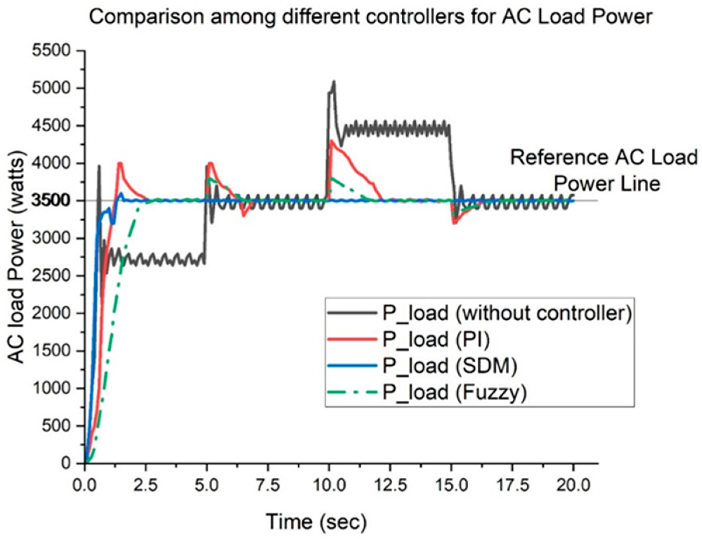
In this system, the irradiance variation that is shown in Figure 2 is considered. Figure 19 shows the common AC load power profile. The red line represents the performance of the PI controller, which shows abrupt overshoots whenever there is a change in irradiance levels. To address this issue, a second control strategy, i.e., the fuzzy logic controller, is implemented. This controller, depicted by the green line, effectively reduces overshoot; however, its main limitation is a slower response time, taking longer to stabilize and track the reference power. The proposed SDM controller, shown by the blue line, provides the best performance. Due to its specialized structure, the SDM controller can swiftly detect and respond to subtle fluctuations in the reference power, minimizing most disturbances in the AC bus power.
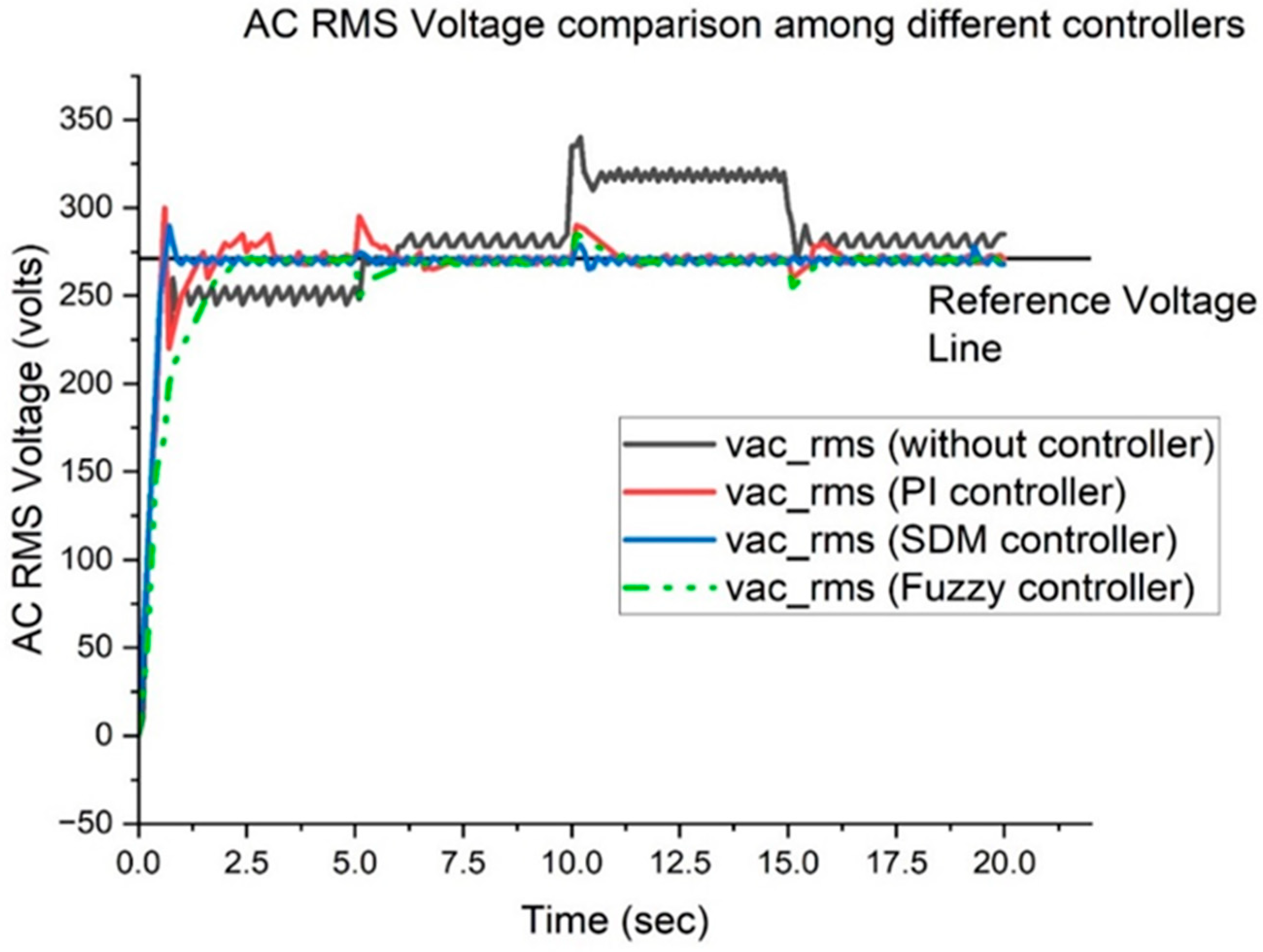
A similar trend in controller performance is observed for the AC bus voltage in Figure 20, where each controller demonstrates comparable behavior to its performance in regulating AC bus power.
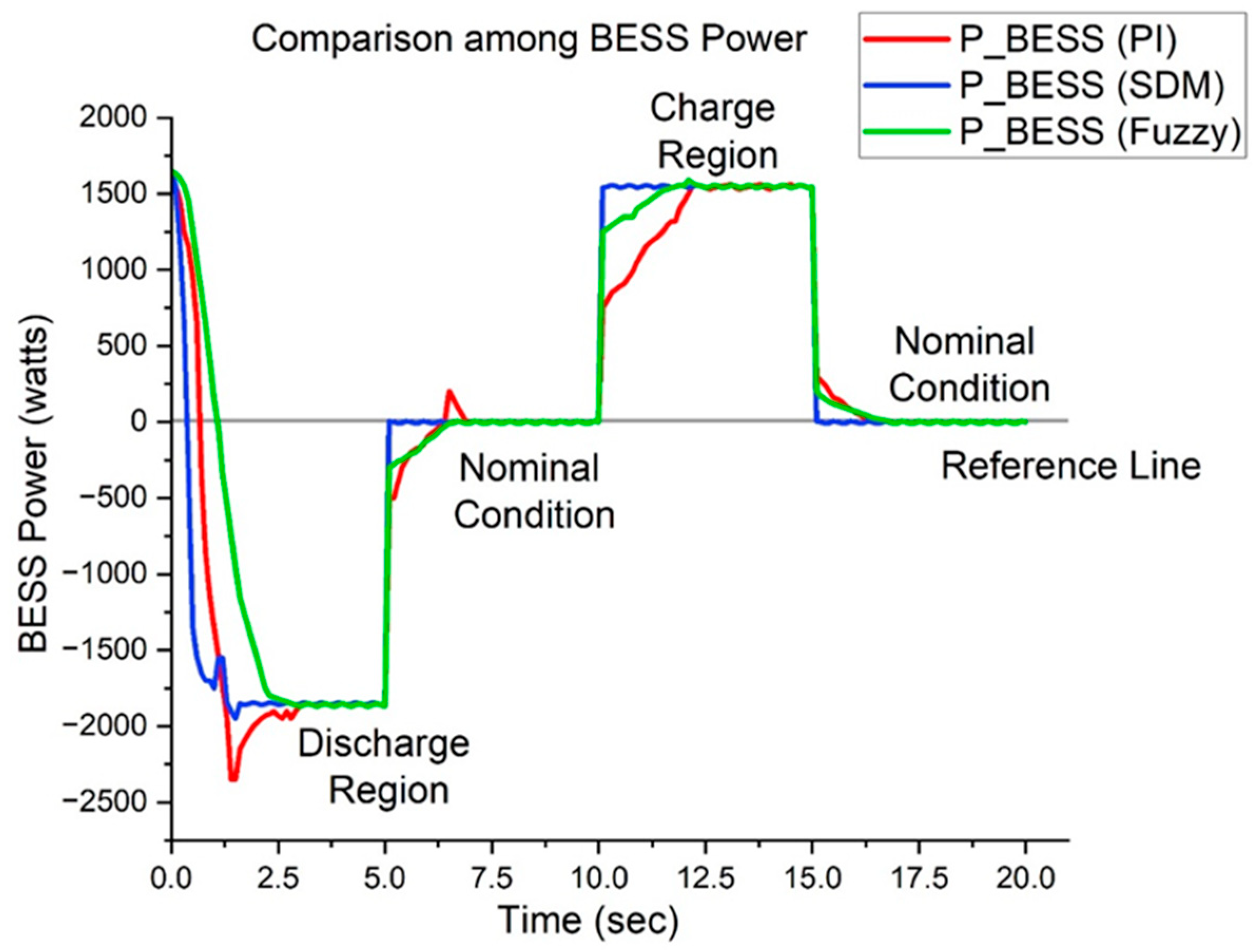
Figure 21 shows the BESS power. The proposed SDM controller is optimal for managing the battery’s charging and discharging cycles, as it produces fewer overshoots than the PI controller and achieves faster convergence compared to the fuzzy logic controller.

5.3. Performance of Different Controllers for Hybrid AC Microgrid with Two BESS

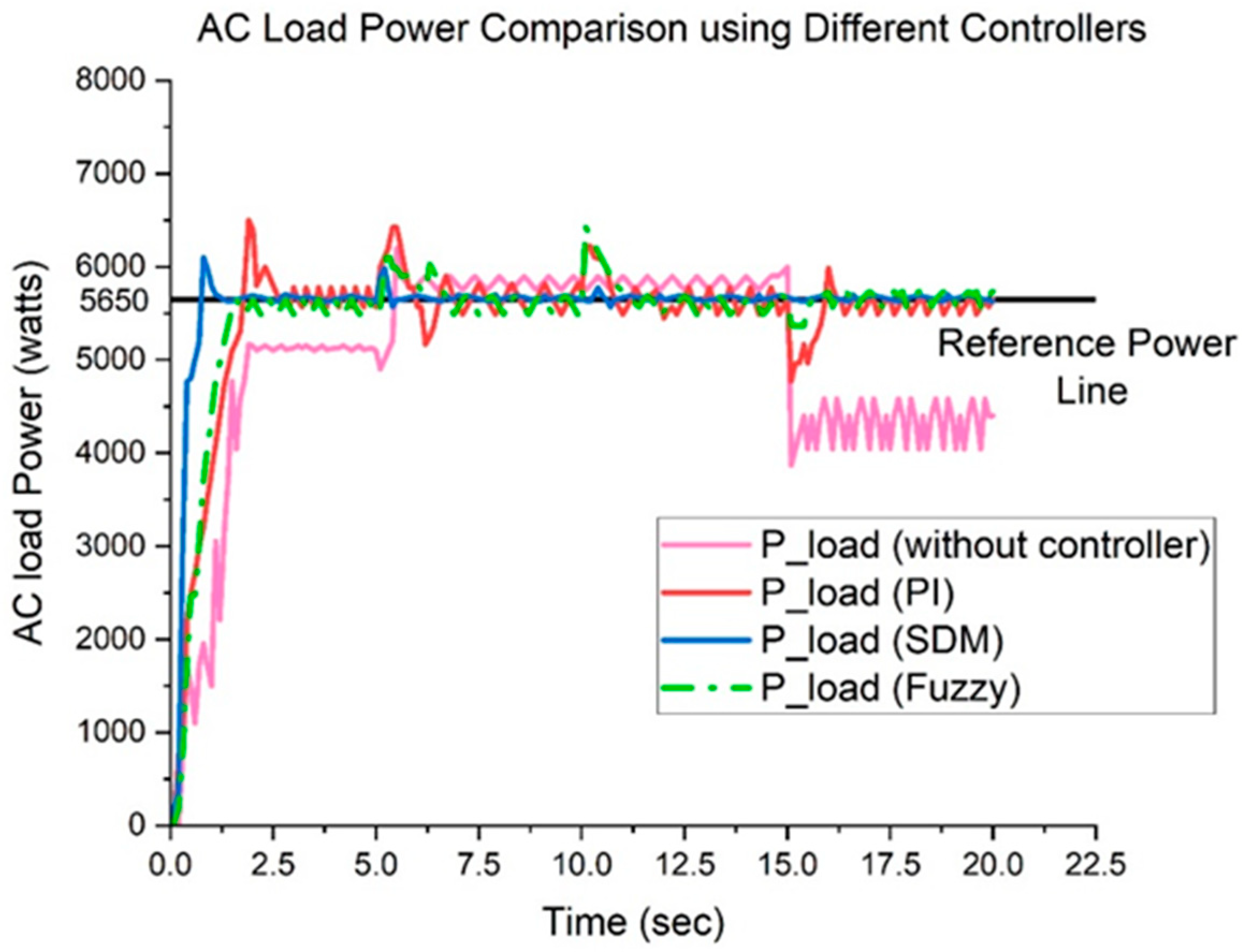
Figure 22 shows the common AC load power profile. The red line represents the performance of the PI controller. Although suitable for this system, the PI controller shows significant overshoots whenever irradiance levels change, posing a risk to household appliances powered by the microgrid. The fuzzy logic controller effectively reduces the overshoot observed with the PI controller, as shown by the green line. In contrast, the SDM controller illustrated by the blue line demonstrates the best performance.
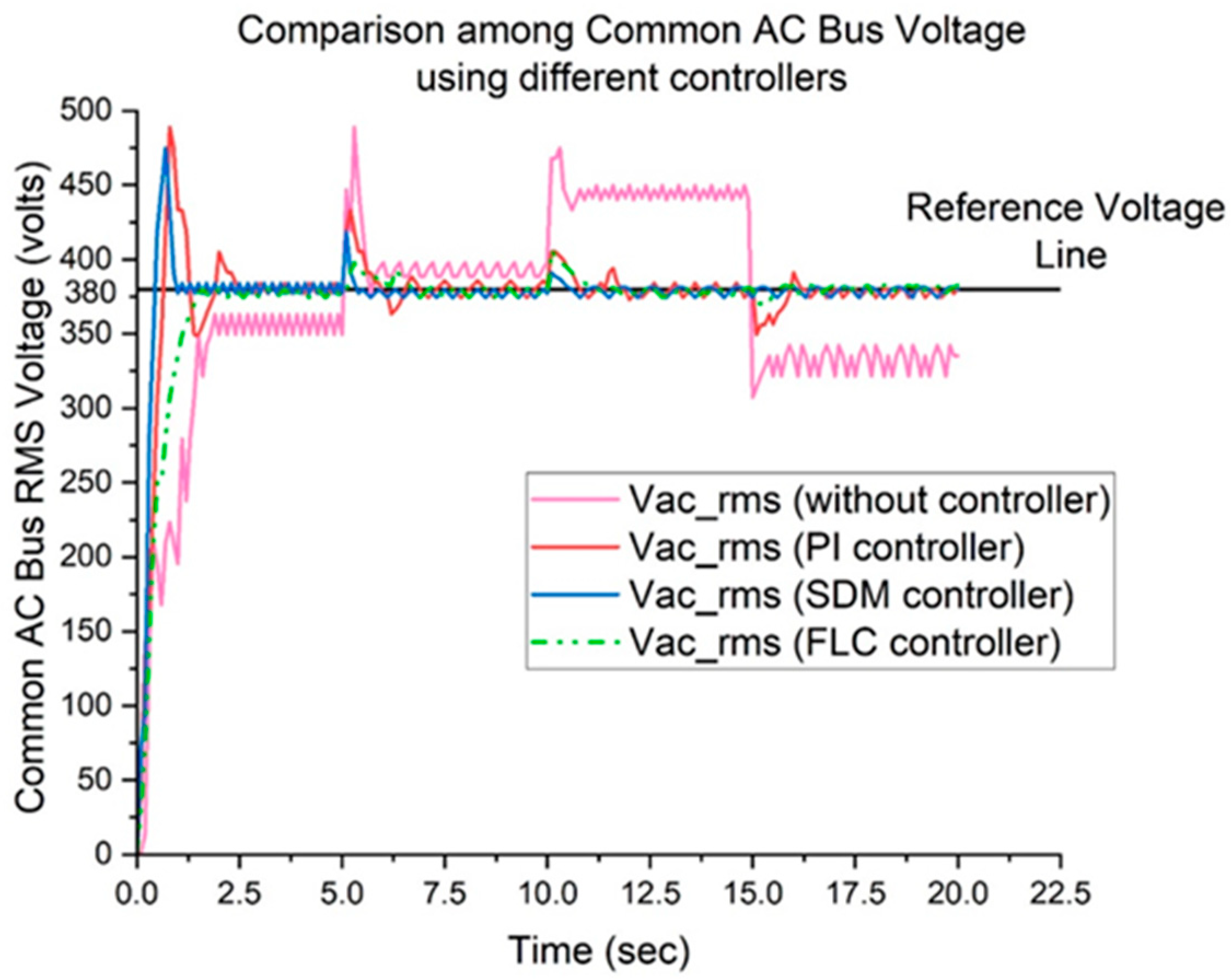
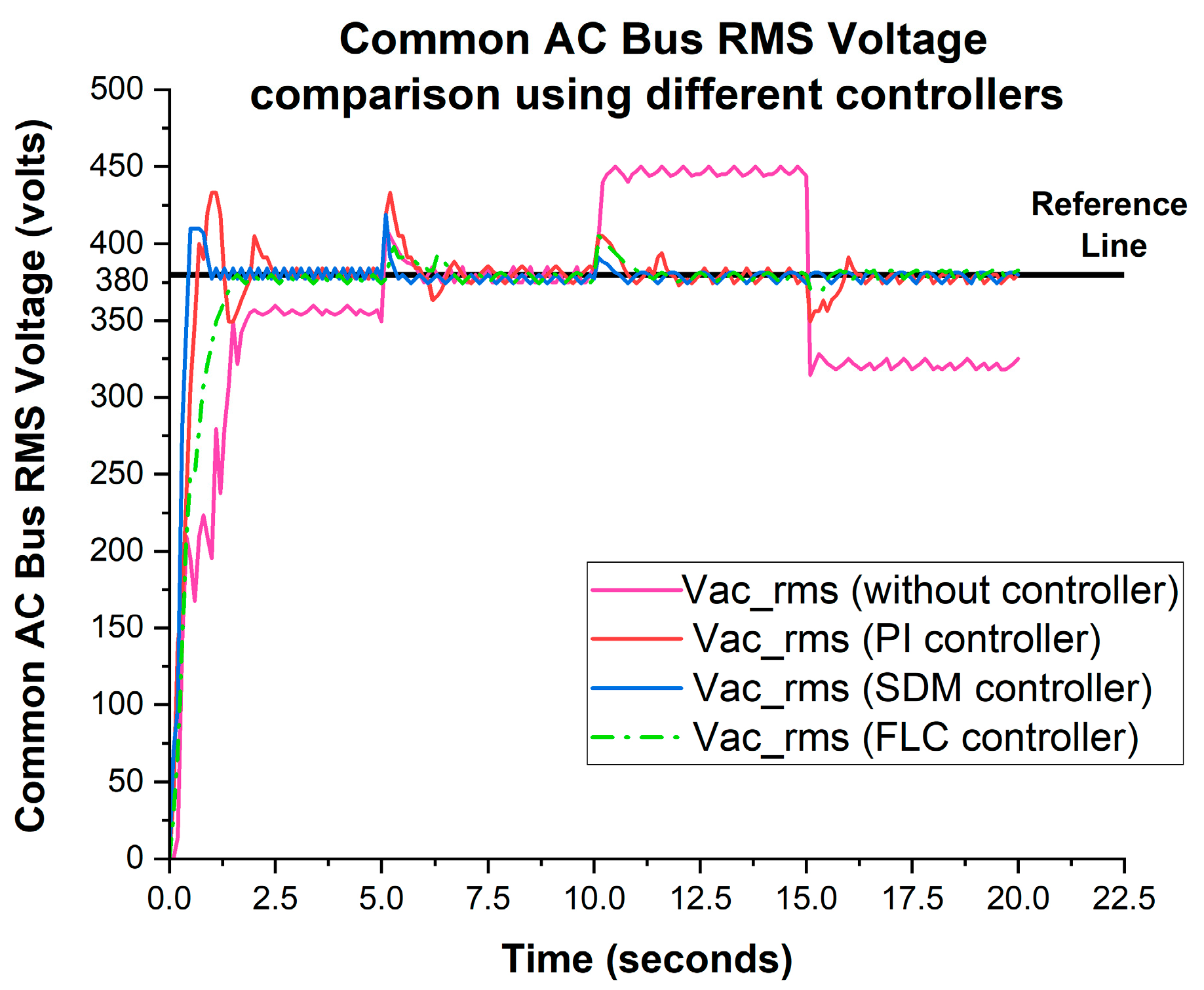
In case of the AC bus voltage (Figure 23), we observe a very similar performance by the three different controllers as was seen in case of the AC bus power.
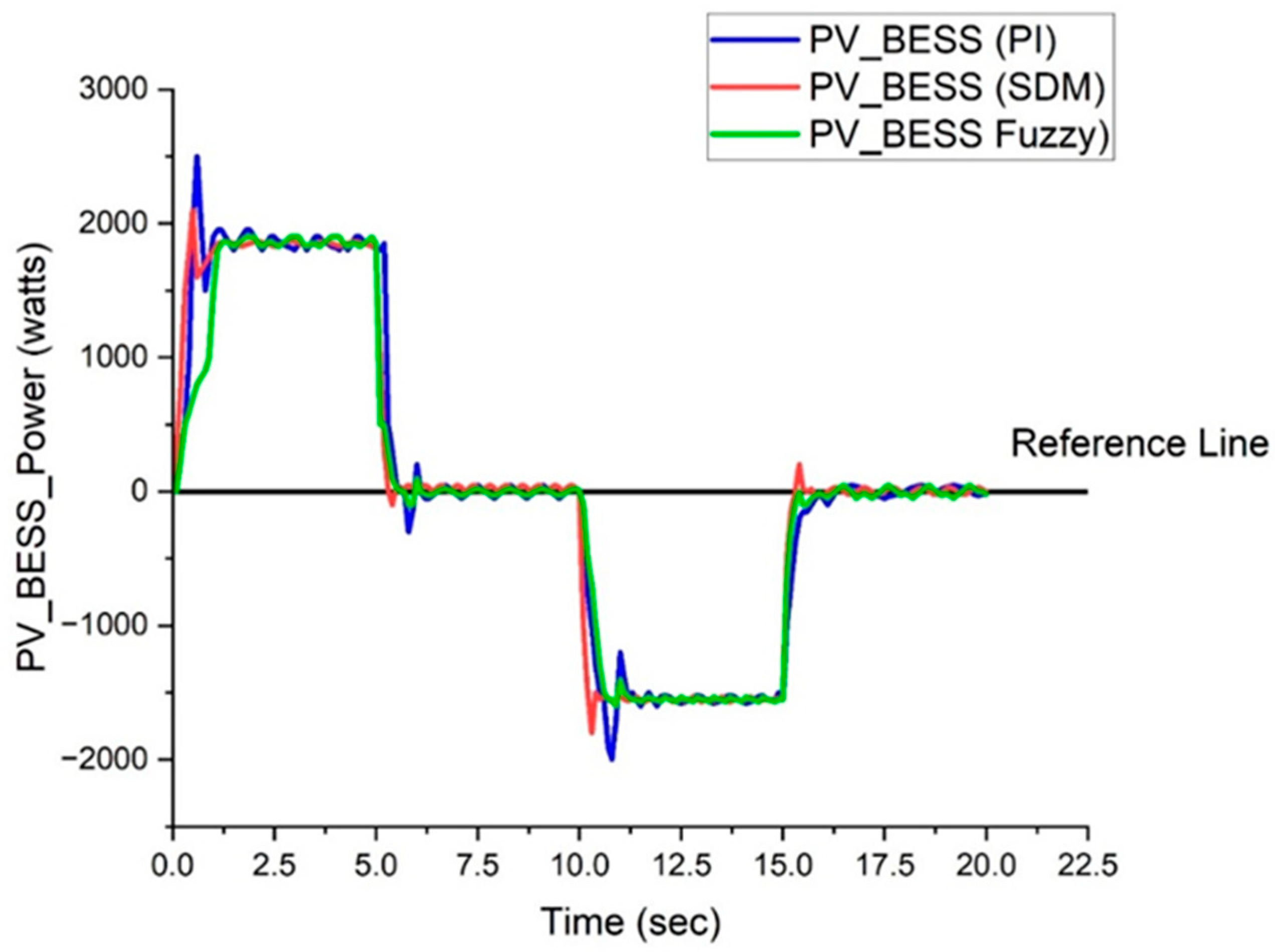
Figure 24 shows the PV_BESS power. The charging and discharging cycles are best handled by the SDM controller as it has less overshoots than the PI controller and can converge faster than the fuzzy logic controller.
In the case of the wind BESS power (Figure 25), the charging and discharging cycles are also best handled by the SDM controller as it has less overshoots than the PI controller and can converge faster than the fuzzy logic controller.

5.4. Performance of Different Controllers for Single Battery Hybrid Microgrid System

In this design, all the key components are exactly the same as described in Figure 1. The only disparity is that a single BESS has been used here at the common AC bus. Here, the bidirectional inverter, VSC has been used with the BESS. In Figure 26, the red line shows the performance of the PI controller. The performance of the fuzzy logic controller is depicted by the green line. We observed the best performance from the proposed SDM controller depicted by the blue line. In the case of the AC bus voltage (Figure 27), we observe a very similar performance by the three different controllers as was seen in case of the AC bus power.
In summary, the reduced AC bus voltage error significantly enhances the overall stability of microgrids by ensuring better voltage regulation, minimizing fluctuations that could destabilize sensitive loads, and improving power quality. This stability fosters efficient power distribution, reduces the risk of component failures, and supports the seamless integration of renewable energy sources and distributed energy resources (DERs). The SDM controller achieves reduced AC bus voltage and power error. The SDM controller provides good voltage and power regulation in AC microgrids by selectively prioritizing control actions based on dynamic system conditions, allowing it to address disturbances and maintain stability effectively. Its design emphasizes adaptive and discriminative decision-making, enabling precise control of voltage levels and power flows, even in the presence of fluctuating renewable energy inputs.
In Figure 28, the BESS power is shown. The charging and discharging cycles are best handled by the proposed SDM controller as it has less overshoots than the PI controller and can converge faster than the fuzzy logic controller.

5.5. Index-Based Performance Comparison

To quantify the performance of the controllers, some numerical metrics, i.e., indexes as shown in Table 14, Table 15, Table 16 and Table 17 for all four microgrid systems, have been considered. We integrated the battery powers over the entire run time, i.e., t = 20 s. This gave us the total energy of the battery energy storage systems. The controller which has the lowest amount of energy is said to be the best performer. So, we saw that the SDM controller gave the best result. Also, in terms of voltage regulation, the voltage deviations were integrated over the entire runtime (20 s). In this case, again, the controller with the smallest value is accepted as the best performer and we see in all four systems, the SDM controller gives the best result.

6. Proposed Improved Ensemble Method (SAMME AdaBoost)-Based Cyberattack Detection System for Hybrid Microgrid

In this work, we focused on improving the existing Ensemble Learning method in such a way that it can handle multiclass classification problems with improved efficiency. This is how we came to apply the improved version of an ensemble-learning-based model for cyberattack detection in microgrid systems. The SAMME (stagewise additive modeling using a multiclass exponential loss function) is an adaptation of the AdaBoost (Adaptive Boosting) algorithm specifically designed for handling multiclass classification tasks [38]. While AdaBoost was originally intended for binary classification, SAMME extends its capability to work with multiple classes by introducing a multiclass exponential loss function. In SAMME, weak classifiers are trained sequentially, with each subsequent classifier focusing more on the instances misclassified by previous ones. Unlike binary AdaBoost, which calculates the classifier’s weight based on the error rate, SAMME also incorporates the number of classes, giving it a unique method for calculating the influence of each classifier in the ensemble. This approach allows SAMME to generate a powerful ensemble of weak classifiers that can handle complex, multiclass data. When combined with decision trees as base learners, SAMME effectively boosts accuracy by emphasizing difficult cases and reducing errors over multiple iterations, ultimately creating a strong, adaptable model for multiclass problems.
A detailed flowchart of the SAMME AdaBoost algorithm is given below in Figure 29. The flowchart for SAMME AdaBoost provides a visual structure of how the algorithm works for multi-class classification, extending traditional AdaBoost, which is limited to binary classification.
A detailed description of the algorithm is provided as follows:
i.
Start:
Begin with the training dataset, where each instance has a label belonging to one of several classes.
ii.
Initialize Weights:
Initialize weights for each instance in the dataset, w i = 1 N , where N is the total number of samples.
iii.
Iteration over Boosting Rounds (Loop):
For each boosting round T, the following is performed:
  • Step A: Train Weak Classifier:
Train a weak classifier (e.g., decision stump) on the training data, using the current sample weights.
  • Step B: Calculate Error Rate:
Calculate the weighted error rate e t of the weak classifier, using Formula (5), which is the sum of the weights of the misclassified samples.
e t = i = 1 N w i . I ( y i h t ( x i ) ) i = 1 N w i
  • Step C: Compute Classifier Weight:
Compute the classifier’s weight t using Formula (6).
t = ln ( 1 e t e t ) + ln ( K 1 )
where K is the number of classes. This step ensures that the classifier weight is adjusted for multi-class settings.
  • Step D: Update Sample Weights:
Update the weights of each instance based on whether it was correctly or incorrectly classified. Weights of the misclassified samples should increase, while weights of the correctly classified samples should decrease. To achieve this, Formula (7) is used.
w i ( t + 1 ) = w i t   X   e x p ( t . I ( y i h t ( x i ) )
  • Step E: Normalize Weights:
Normalize the weights to ensure they sum to 1, preparing them for the next iteration.
iv.
Aggregate Weak Classifiers:
After completing all the boosting rounds, combine the weak classifiers based on their weights t to form a strong classifier. Each classifier’s vote is scaled by its t value. Formula (8) is used to aggregate the weak classifiers.
F k x = t = 1 T t . I ( h t x = k )
v.
Generating Probability of each class:
After aggregating the weak classifiers, Softmax Function, e F k x , is used to generate probability of each class.
vi.
Class Prediction:
For a new instance, each weak classifier generates the probability for each class. The final prediction is the class with the highest weighted probability.
vii.
End:
Output the final strong classifier capable of multi-class predictions.
This flow ensures SAMME adapts AdaBoost to handle multi-class data by modifying the error calculations and weight updates accordingly.

6.1. Application of Improved Ensemble Method in Detecting Cyberattacks

In this problem, we have three classes, where Class 0 is ‘No Attack’, Class 1 is ‘FDI Attack’, and Class 2 is ‘DoS Attack’. The detailed mathematical derivation of FDI and DoS attacks have been shown in [24]. SAMME is particularly well suited to this multiclass detection problem because it does not rely on a one vs. rest or one vs. one approach, which can sometimes reduce performance or add complexity in multiclass scenarios. Instead, SAMME works natively on the three classes, streamlining the detection process and allowing the model to handle overlapping patterns between the “no attack”, “FDI”, and “DoS” classes more effectively. Its boosting process also ensures the model is robust against misclassification and can adjust to focus on the most challenging cases, such as minor variances between the FDI and DoS attacks, ultimately increasing detection accuracy across all three classes.
The SAMME AdaBoost works in the following steps to detect the three different classes in this case:
i.
Training the Model on Three Classes: In this scenario, each weak classifier in the ensemble will iteratively focus on distinguishing among the three classes, “no attack”, “FDI attack”, and “DoS attack”. The SAMME algorithm adjusts the weights of instances after each weak learner, giving more focus to instances that are misclassified in the previous round. This adjustment enables the model to improve its accuracy on difficult cases over time.
ii.
Handling Misclassification with Class Weights: SAMME calculates the influence of each weak classifier based on the number of classes, taking a unique approach to weighting. The algorithm adjusts each classifier’s weight based on its accuracy across all three classes, emphasizing the challenging-to-predict classes (e.g., if FDI and DoS attacks are harder to distinguish from each other or from the “no attack” class). This way, SAMME learns to differentiate each attack type by refining the decision boundaries between the three classes.
iii.
Sequential Training to Boost Accuracy: SAMME iterates through multiple weak classifiers, each one trained to improve on the errors of the previous classifiers. This sequential boosting of each learner’s focus on difficult cases results in a strong ensemble model capable of accurately categorizing whether a situation represents “no attack”, an “FDI attack”, or a “DoS attack”.
Simulated data from MATLAB are extracted to create the dataset for this detection purpose. The attacks were implemented on a hybrid microgrid with two batteries (Figure 1).
The dataset consists of the following features:
1.
Irradiance
10.
PV BESS Power
2.
PV Power
11.
PV BESS SoC
3.
PV Output Voltage
12.
Wind BESS Power
4.
Wind Power
13.
Wind BESS SoC
5.
Wind Output Voltage
14.
AC Bus Voltage
6.
DC Bus Voltage 1
15.
AC Load Power
7.
DC Bus Voltage 2
8.
PV Inverter Output Power
9.
Wind Inverter Output Power
In total, 250,000 instances were made available. Up to 60% of the data, i.e., 150,000 instances, was used to train the model, and the remaining instances were used for testing.

6.2. Comparison with Existing Ensemble Learning-Based Method

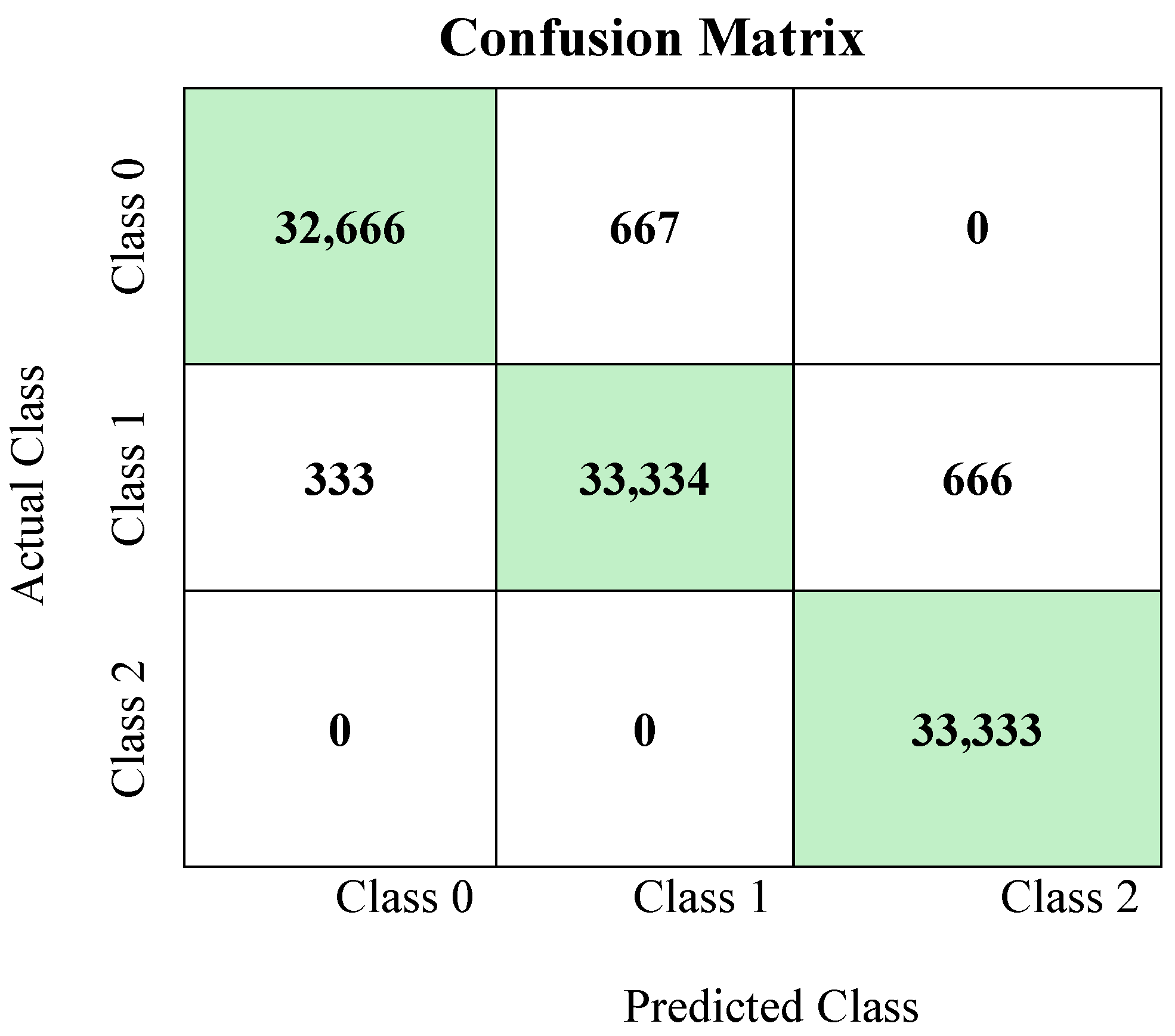
The performance of the proposed SAMME AdaBoost method has been compared with that of the ensemble learning (one class AdaBoost) model that was reported in [24]. The confusion matrix shown in Figure 30 represents the performance of SAMME AdaBoost. The model performed quite well, with the highest values along the diagonal, indicating correct classifications for each class. For Class 0, 32,666 instances were correctly classified, with 667 instances misclassified as Class 1. For Class 1, 33,334 instances were classified correctly, with 333 instances misclassified as Class 0 and 666 as Class 2. For Class 2, all 33,333 instances were correctly classified, with no misclassifications. Overall, the model shows high accuracy, almost 99.33%. The color intensity in the heatmap reflects the count of each classification outcome, with higher counts shown in deeper red in Figure 30.

Performance Metrics

The effectiveness of the proposed method and conventional ML models is evaluated in terms of the following performance indicators (9–12), where TP refers to True Positive, TN refers to True Negative, FP refers to False Positive, and FN refers to False Negative. In this work, we converted the three-class problem into three separate binary classification problems, one for each class against the others. After that, each index was applied to these binary cases. This is called the ‘One vs. All’ technique.
A v e r a g e   A c c u r a c y = T P + T N T P + F P + F N + T N
F 1 S c o r e = 2 · R e c a l l · P r e c i s i o n R e c a l l + P r e c i s i o n
P r e c i s i o n = T P T P + F P
R e c a l l = T P T P + F N
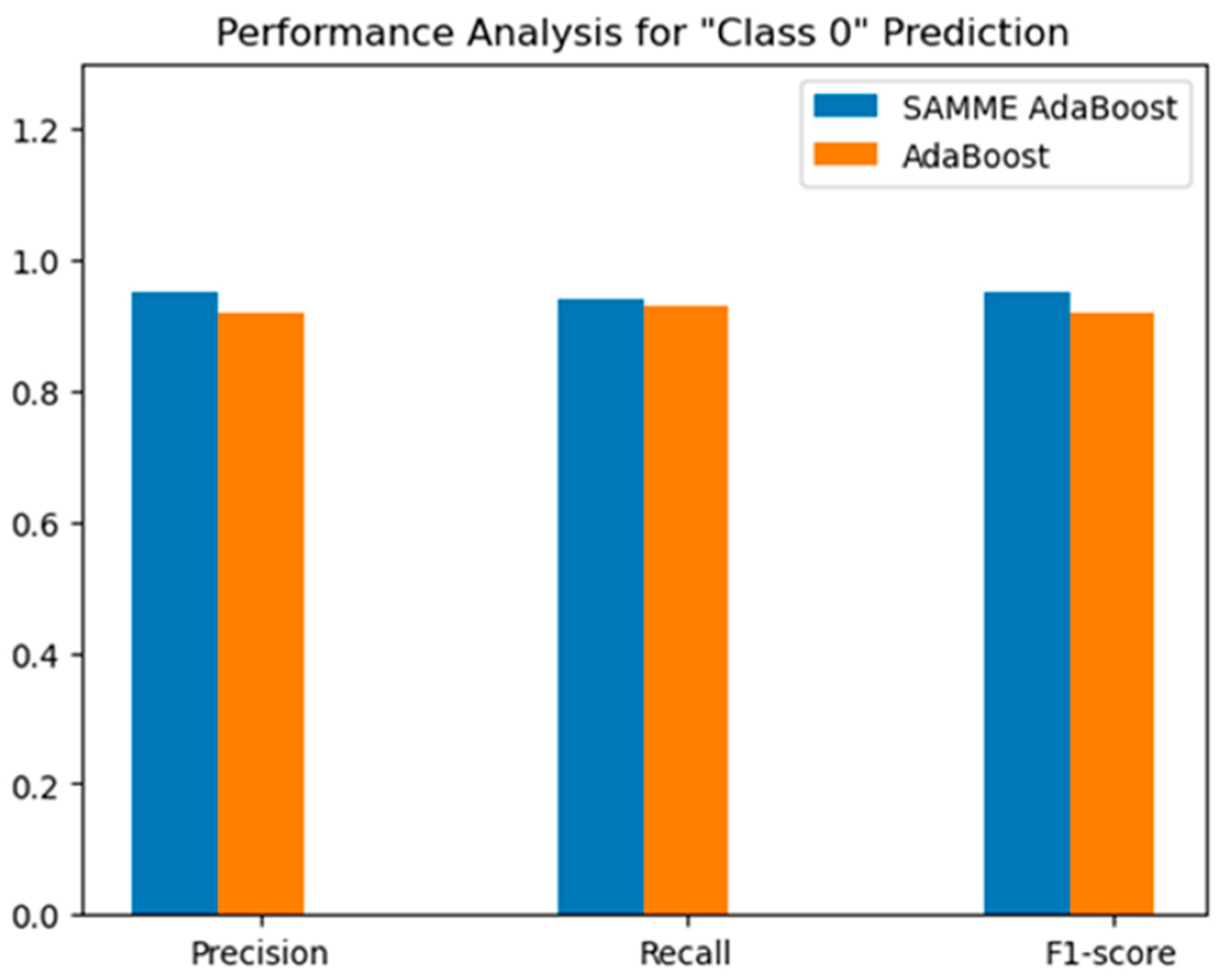
Figure 31 compares the performance metrics—precision, recall, and F1-score—of the two models, SAMME AdaBoost and existing AdaBoost, for predicting “Class 0: Normal Scenario”. Precision measures the model’s accuracy in predicting Class 0, recall measures its ability to capture all true instances of Class 0, and the F1-score provides a balance between precision and recall. The SAMME AdaBoost depicts a better performance than the normal AdaBoost technique in all three metrics.
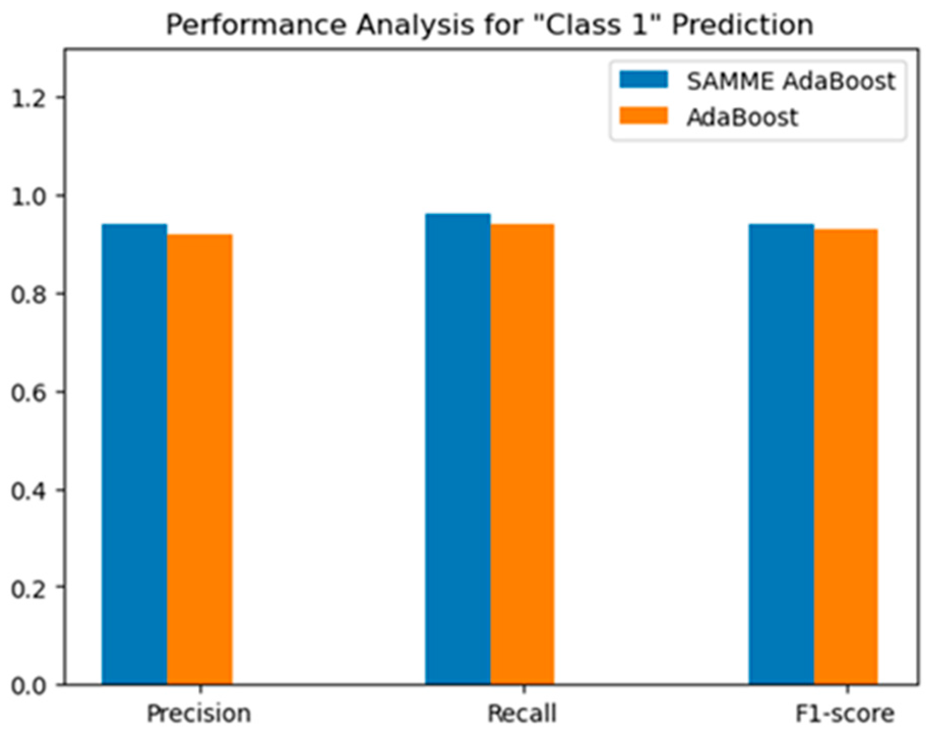
For Class 1: FDI Attack detection, in all three metrics, i.e., precision, recall and F1-score, the SAMME AdaBoost depicts a better performance than the normal AdaBoost technique, as shown in Figure 32.
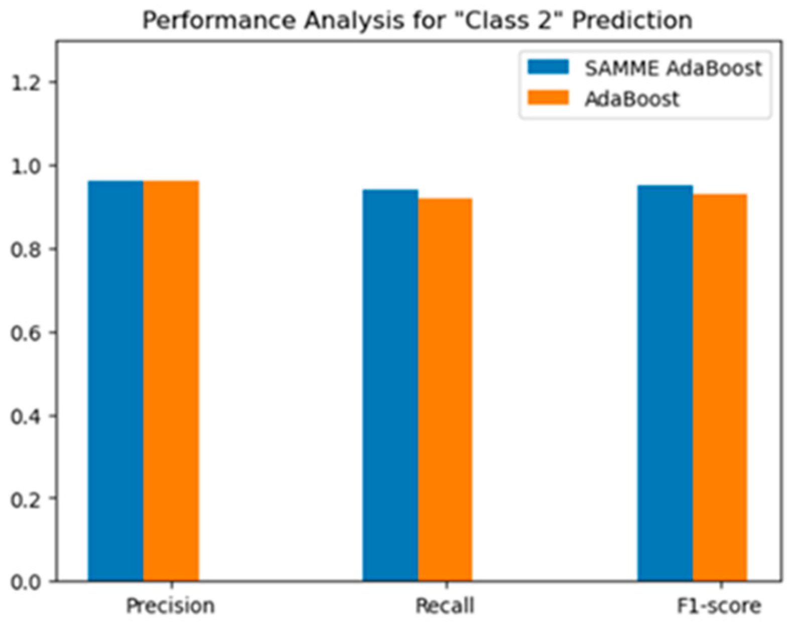
For Class 2: DoS Attack detection, in terms of the three metrics, i.e., precision, recall and F1-score, the SAMME AdaBoost depicts a better performance in terms of precision than the normal AdaBoost technique, as shown in Figure 33.
The results are summarized in Table 18.

7. Conclusions

This work can be broadly divided into two sections. The first section researches the performance of different controllers for a BESS in handling the intermittent tendency of PV-based microgrid systems. The second section discusses how integrating IoT-enabled devices in the microgrid infrastructure can open up new cyberattacks, what its impact can be on the BESS controller and overall stability of the system, and finally a new detection technique that can help make the system cyber resilient. In this work, extensive simulations have been carried out using the Matlab/Simulink software. This paper can be concluded as follows:
A sigma-delta modulation controller was developed to minimize the fluctuations in power and voltage due to the intermittent tendency of solar and wind generation sources.
The performance of the novel sigma-delta modulation controller was compared with that of the conventional PI and fuzzy logic controllers. Numerical results demonstrate the improved performance of the proposed SDM controller, with a 35% reduction in AC bus voltage error compared to conventional PI and FLC controllers.
The impact of two of the most common cyberattacks on the BESS controller of four PV-based microgrid systems was observed and analyzed.
The improved ensemble learning (SAMME AdaBoost)-based cyberattack detection technique was developed to make the IoT-enabled BESS-integrated microgrid systems more cyber resilient. The proposed SAMME AdaBoost detection method achieved superior accuracy with an F1 score of 95%, outperforming the existing ensemble approaches.
It is important to note that practical implementation of the SDM controller and SAMME AdaBoost method in microgrids requires components like sensors for real-time data collection, embedded controllers, communication infrastructure, and power converters for system control. Additional essentials include computational hardware for model inference and software for machine learning and supervisory control. The potential cost implications of implementing the SDM controller in microgrids include the initial expenses for hardware components such as sensors, controllers, and communication infrastructure, as well as software development and integration costs. Additionally, ongoing costs for system maintenance, data management, and updates to the SDM model to adapt to dynamic microgrid conditions could impact long-term operational budgets.
The potential limitations of the proposed SDM controller in microgrids include its reliance on high-quality, real-time data, which can be challenging in noisy or resource-constrained environments. Thus, this work can be extended by considering realistic solar irradiance and wind speed variation data, considering 24 h data pattern for solar irradiance and wind speed variation, optimizing controller parameters using the appropriate algorithms, implementing the system in hardware to address practical challenges like communication delays, and integrating 5G for seamless connectivity between energy sources, BESS, and SCADA. It can also involve the incorporation of additional renewable energy sources such as fuel cells, the analysis of advanced cyberattacks like the aurora attack, and the exploration of ML-based techniques like the envelope model for anomaly detection using Support Vector Machines (SVMs), Gaussian mixture models, or autoencoders. Furthermore, effective cyberattack mitigation strategies, such as the Zero Trust concept, can be developed to enhance microgrid security.

Author Contributions

Conceptualization, S.A.S. and M.H.A.; methodology, S.A.S.; software, S.A.S.; validation, S.A.S. and M.H.A.; formal analysis, S.A.S. and M.H.A.; investigation, S.A.S. and M.H.A.; resources, M.H.A.; data curation, S.A.S.; writing—original draft preparation, S.A.S.; writing—review and editing, M.H.A.; visualization, M.H.A.; supervision, M.H.A.; project administration, M.H.A.; funding acquisition, M.H.A. All authors have read and agreed to the published version of the manuscript.

Funding

This research received no external funding.

Data Availability Statement

Data are contained within the article.

Acknowledgments

The authors acknowledge the financial support from the Electrical and Computer Engineering Department of the University of Memphis, USA, to perform this work.

Conflicts of Interest

The authors declare no conflicts of interest.

Appendix A

Table A1. Electrical Specification of PV Panel.
Sl. No.ParametersValues
1.Maximum Power @ 800 W/m25300 W
2.Voltage at maximum power point 180 V
3.Current at maximum power point 29.9 A
4.Nominal Power @ 600 W/m23750 W
5.Open Circuit Voltage150 V
6.Short Circuit Current25 A
Table A2. Parameters of PV Boost Converter.
Sl. No.DescriptionValues
1.Output voltage (Vout)400 V
2.Inductance (L)46 mH
3.Capacitance (C)27.1 µF
4.Switching frequency (fs)10 kHz
Table A3. Specification of Bi-Directional Buck Boost Converter for BESS.
Sl. No.DescriptionValues
1.Switching frequency (fs)10 KHz
2.Inductance, L0.5 mH
3.Boost capacitance, Cboost17.3 µF
4.Buck capacitance, Cbuck50.3 µF
Table A4. Specification of BESS.
Sl. No.DescriptionValues
1.Initial State of Charge45%
2.Nominal Voltage320 V
3.Rated Capacity100 Ah
4.Battery Response Time1 s
Table A5. Specification of LC Filter in Transmission Line.
Sl. No.DescriptionValues
1.Inductance, L0.213 mH
2.Capacitance, C14.32 µF

References

  1. Makhanya, T.; Sewsunker, R.; Pillay, N. A Distributed Standalone Solar PV and Battery Energy Storage System DC Microgrid. In Proceedings of the 2023 31st Southern African Universities Power Engineering Conference (SAUPEC), Johannesburg, South Africa, 24–26 January 2023; pp. 1–6. [Google Scholar] [CrossRef]
  2. Li, X.; Ma, R.; Gan, W.; Yan, S. Optimal Dispatch for Battery Energy Storage Station in Distribution Network Considering Voltage Distribution Improvement and Peak Load Shifting. J. Mod. Power Syst. Clean Energy 2022, 10, 131–139. [Google Scholar] [CrossRef]
  3. Šriupša, L.; Dosinas, J.; Vaitkūnas, M.; Jonaitis, A.; Baronas, A.; Gudžiūtė, S. Employment of a DC microgrid for more efficient use of solar energy in household buildings. In Proceedings of the 2022 IEEE 63th International Scientific Conference on Power and Electrical Engineering of Riga Technical University (RTUCON), Riga, Latvia, 10–12 October 2022; pp. 1–5. [Google Scholar] [CrossRef]
  4. Hofer, J.; Svetozarevic, B.; Schlueter, A. Hybrid AC/DC building microgrid for solar PV and battery storage integration. In Proceedings of the 2017 IEEE Second International Conference on DC Microgrids (ICDCM), Nuremburg, Germany, 27–29 June 2017; pp. 188–191. [Google Scholar] [CrossRef]
  5. Mahmud, R.; Hossain, M.A.; Pota, H. Robust Nonlinear Controller Design for Islanded Photovoltaic System with Battery Energy Storage. In Proceedings of the 2020 IEEE International Conference on Power Electronics, Smart Grid and Renewable Energy (PESGRE2020), Cochin, India, 2–4 January 2020; pp. 1–6. [Google Scholar] [CrossRef]
  6. Naqvi, S.B.Q.; Kumar, S.; Singh, B. A PV-Battery System Operating in Islanded and Grid Connected Modes with Shunt Active Filter Capability. In Proceedings of the 2020 IEEE Industry Applications Society Annual Meeting, Detroit, MI, USA, 10–16 October 2020; pp. 1–8. [Google Scholar] [CrossRef]
  7. Madadi, M.; Bhattacharya, S. Adaptive Nonlinear Droop Control with Dynamic State-of-Charge Balancing Capability for Batteries in DC Microgrids. In Proceedings of the 2021 IEEE Applied Power Electronics Conference and Exposition (APEC), Phoenix, AZ, USA, 14–17 June 2021; pp. 55–61. [Google Scholar]
  8. Yang, Y.; Xu, D.; Ma, T.; Su, X. Adaptive Cooperative Terminal Sliding Mode Control for Distributed Energy Storage Systems. IEEE Trans. Circuits Syst. I Regul. Pap. 2021, 68, 434–443. [Google Scholar] [CrossRef]
  9. Patel, S.; Ghosh, A.; Ray, P.K. Adaptive power management in PV/Battery integrated hybrid microgrid system. In Proceedings of the 2022 IEEE International Conference on Power Electronics, Smart Grid, and Renewable Energy (PESGRE), Trivandrum, India, 2–5 January 2022; pp. 1–6. [Google Scholar] [CrossRef]
  10. Akpolat, A.N.; Habibi, M.R.; Baghaee, H.R.; Dursun, E.; Kuzucuoğlu, A.E.; Yang, Y.; Dragičević, T.; Blaabjerg, F. Dynamic Stabilization of DC Microgrids Using ANN-Based Model Predictive Control. IEEE Trans. Energy Convers. 2022, 37, 999–1010. [Google Scholar] [CrossRef]
  11. Patnaik, S.; Kumar, M.R.; Mishra, S.K.; Gautam, S.P. Fuzzy Controller Based DC Bus Voltage Stabilization of Hybrid Energy Storage System for PV Applications with Charging Efficiency Analysis. In Proceedings of the 2023 International Conference on Communication, Circuits, and Systems (IC3S), Bhubaneswar, India, 26–28 May 2023; pp. 1–6. [Google Scholar] [CrossRef]
  12. Gao, Y.; Wang, S.; Dragicevic, T.; Wheeler, P.; Zanchetta, P. Artificial Intelligence Techniques for Enhancing the Performance of Controllers in Power Converter-Based Systems—An Overview. IEEE Open J. Ind. Appl. 2023, 4, 366–375. [Google Scholar] [CrossRef]
  13. Roy, S.; Chishti, F.; Singh, B.; Panigrahi, B.K. GNLMP Control for Solar PV-Battery Based Microgrid With Ms-EPLL Syn-chronization. IEEE Trans. Ind. Appl. 2022, 58, 6599–6611. [Google Scholar] [CrossRef]
  14. Saha, J.; Liang, S.L.W.; Jun, N.F.C.; How, J.T.W.; Ann, L.; Panda, S.K. Transformation of Existing Commercial Building Cluster Towards Renewable Rich Microgrid: A Case Study for Marina Bay Sands Singapore. In Proceedings of the 2022 IEEE PES Innovative Smart Grid Technologies—Asia (ISGT Asia), Singapore, 1–5 November 2022; pp. 485–489. [Google Scholar] [CrossRef]
  15. Li, Q.; Li, F.; Zhang, J.; Ye, J.; Song, W.; Mantooth, A. Data-driven Cyberattack Detection for Photovoltaic (PV) Systems through Analyzing Micro-PMU Data. In Proceedings of the 2020 IEEE Energy Conversion Congress and Exposition (ECCE), Detroit, MI, USA, 11–15 October 2020; pp. 431–436. [Google Scholar] [CrossRef]
  16. Tareq, A.A.; Rana, J.; Mostofa, R.; Rahman, S. Impact of IoT and Embedded System on Semiconductor Industry A Case Study. Control Syst. Optim. Lett. 2024, 2, 211–216. [Google Scholar] [CrossRef]
  17. Obrien, V.; Trevizan, R.D.; Rao, V.S. Detecting False Data Injection Attacks to Battery State Estimation Using Cumulative Sum Algorithm. In Proceedings of the 2021 North American Power Symposium (NAPS), College Station, TX, USA, 14–16 November 2021; pp. 1–6. [Google Scholar] [CrossRef]
  18. Tareq, A.A.; Mostofa, R.; Rana, J.; Rahman, S. A Comprehensive Review of Intelligent Home Automation Systems Using Embedded Devices and IoT. Control Syst. Optim. Lett. 2024, 2, 198–203. [Google Scholar] [CrossRef]
  19. Mao, J.; Zhang, M.; Xu, Q. CNN and LSTM based Data-driven Cyberattack Detection for Grid-connected PV Inverter. In Proceedings of the IEEE International Conference on Control and Automation, ICCA, IEEE Computer Society, Naples, Italy, 27–30 June 2022; pp. 704–709. [Google Scholar] [CrossRef]
  20. Ibrahim, H.; Kim, J.; Enjeti, P.; Kumar, P.R.; Xie, L. Detection of Cyber Attacks in Grid-tied PV Systems Using Dynamic Wa-termarking. In Proceedings of the IEEE Green Technologies Conference, IEEE Computer Society, Houston, TX, USA, 30 March–1 April 2022; pp. 57–61. [Google Scholar] [CrossRef]
  21. Mo, Y.; Sinopoli, B. On the Performance Degradation of Cyber-Physical Systems under Stealthy Integrity Attacks. IEEE Trans. Autom. Control 2016, 61, 2618–2624. [Google Scholar] [CrossRef]
  22. Mienye, I.D.; Sun, Y. A Survey of Ensemble Learning: Concepts, Algorithms, Applications, and Prospects. IEEE Access 2022, 10, 99129–99149. [Google Scholar] [CrossRef]
  23. Gaggero, G.B.; Caviglia, R.; Armellin, A.; Rossi, M.; Girdinio, P.; Marchese, M. Detecting Cyberattacks on Electrical Storage Systems through Neural Network Based Anomaly Detection Algorithm. Sensors 2022, 22, 3933. [Google Scholar] [CrossRef] [PubMed]
  24. Saiara, S.A.; Ali, M.H. An Ensemble Learning Based Cyber Attack Detection Technique for BESS Integrated PV System. In Proceedings of the SoutheastCon 2024, Atlanta, GA, USA, 15–24 March 2024; pp. 392–397. [Google Scholar] [CrossRef]
  25. Shahriar Haque, A.S.M.; Rahman, M.M.; Joy, C.J.I.; Hasan, M.S.; Aftabuzzaman, M.; Rahman, M.S. Levelized Cost of Energy and Cost-Benefit Analysis of 230 kV Bulk Power Transmission in Bangladesh. In Proceedings of the 12th International Conference on Electrical and Computer Engineering, ICECE 2022, Dhaka, Bangladesh, 21–23 December 2022; Institute of Electrical and Electronics Engineers (IEEE) Inc.: Piscataway, NJ, USA, 2023; pp. 236–239. [Google Scholar] [CrossRef]
  26. Habib, A.K.M.A.; Hasan, M.K.; Hassan, R.; Islam, S.; Thakkar, R.; Vo, N. Distributed denial-of-service attack detection for smart grid wide area measurement system: A hybrid machine learning technique. Energy Rep. 2023, 9, 638–646. [Google Scholar] [CrossRef]
  27. Hill, P.; Gilbert, J.; Myers, K.; Poudel, B. Inverter-Based Layered Volt-VAR Control Scheme for High-Penetration Microgrids. In Proceedings of the 2024 IEEE Power & Energy Society General Meeting (PESGM), Seattle, WA, USA, 21–25 July 2024; pp. 1–5. [Google Scholar] [CrossRef]
  28. Kakigano, H.; Miura, Y.; Ise, T. Distribution voltage control for DC microgrids using fuzzy control and gain-scheduling technique. IEEE Trans. Power Electron. 2012, 28, 2246–2258. [Google Scholar] [CrossRef]
  29. Ma, W. Optimal Allocation of Hybrid Energy Storage Systems for Smoothing Photovoltaic Power Fluctuations Considering the Active Power Curtailment of Photovoltaic. IEEE Access 2019, 7, 74787–74799. [Google Scholar] [CrossRef]
  30. Pour, S.D.; Eslami, R.; Marzband, M.; Shoja-Majidabad, S. Nonlinear Robust Voltage Regulation and Balanced Demand Re-sponse of an Islanded DC Microgrid. In Proceedings of the 2021 11th Smart Grid Conference (SGC), Tabriz, Iran, 7–9 December 2021; pp. 1–6. [Google Scholar] [CrossRef]
  31. Hasan, M.M.; Jaman, S.; Geury, T.; Hegazy, O. Design and Simulation of a Grid-Connected Two-Stage Bidirectional Converter for a Combined PV-Stationary Energy Storage System. In Proceedings of the 2022 Second International Conference on Sustainable Mobility Applications, Renewables and Technology (SMART), Cassino, Italy, 23–25 November 2022; pp. 1–8. [Google Scholar] [CrossRef]
  32. Gulzar, M.M.; Iqbal, A.; Sibtain, D.; Khalid, M. An Innovative Converterless Solar PV Control Strategy for a Grid Connected Hybrid PV/Wind/Fuel-Cell System Coupled With Battery Energy Storage. IEEE Access 2023, 11, 23245–23259. [Google Scholar] [CrossRef]
  33. Keskar, N.A.; RincÓn-Mora, G.A. A Fast, Sigma–Delta (ΣΔ) Boost DC–DC Converter Tolerant to Wide LC Filter Variations. IEEE Trans. Circuits Syst. II Express Briefs 2008, 55, 198–202. [Google Scholar] [CrossRef]
  34. Rahman, S. Development of Novel Controllers to Address the Misalignment Problem of Dynamic Wireless Charging of Electric Vehicles. Available online: https://digitalcommons.memphis.edu/etd (accessed on 30 September 2024).
  35. Choudhury, A.R.; Pati, S.; Choudhury, A.; Mohanty, K.B. Control of voltage & frequency of a hybrid microgrid using a FLC based bidirectional converter equipped with BESS. In Proceedings of the 2018 Technologies for Smart-City Energy Security and Power (ICSESP), Bhubaneswar, India, 28–30 March 2018; pp. 1–6. [Google Scholar] [CrossRef]
  36. Rahman, M.S.; Ali, M.H. Adaptive Neuro Fuzzy Inference System (ANFIS) Based Control for Misalignment Problem Solution to Vehicle-to-Vehicle Dynamic Wireless Charging System. Authorea Prepr. 2024. [Google Scholar] [CrossRef]
  37. Rahman, M.S.; Ali, M.H. Development of Controllers for Compensating Misalignment in Vehicle-to-Vehicle Dynamic Wireless Charging System. In Proceedings of the IEEE SoutheastCon, Atlanta, GA, USA, 15–24 March 2024; Institute of Electrical and Electronics Engineers Inc.: Piscataway, NJ, USA, 2024; pp. 374–379. [Google Scholar] [CrossRef]
  38. Kurniawan, R.; Gusti, S.K.; Syamsudhuha; Sukamto; Abdillah, R. Predicting Career Trajectories of Information System Graduates Using AdaBoost Algorithm. In Proceedings of the 2023 9th International Conference on Wireless and Telematics (ICWT), Solo, Indonesia, 6–7 July 2023; pp. 1–5. [Google Scholar] [CrossRef]
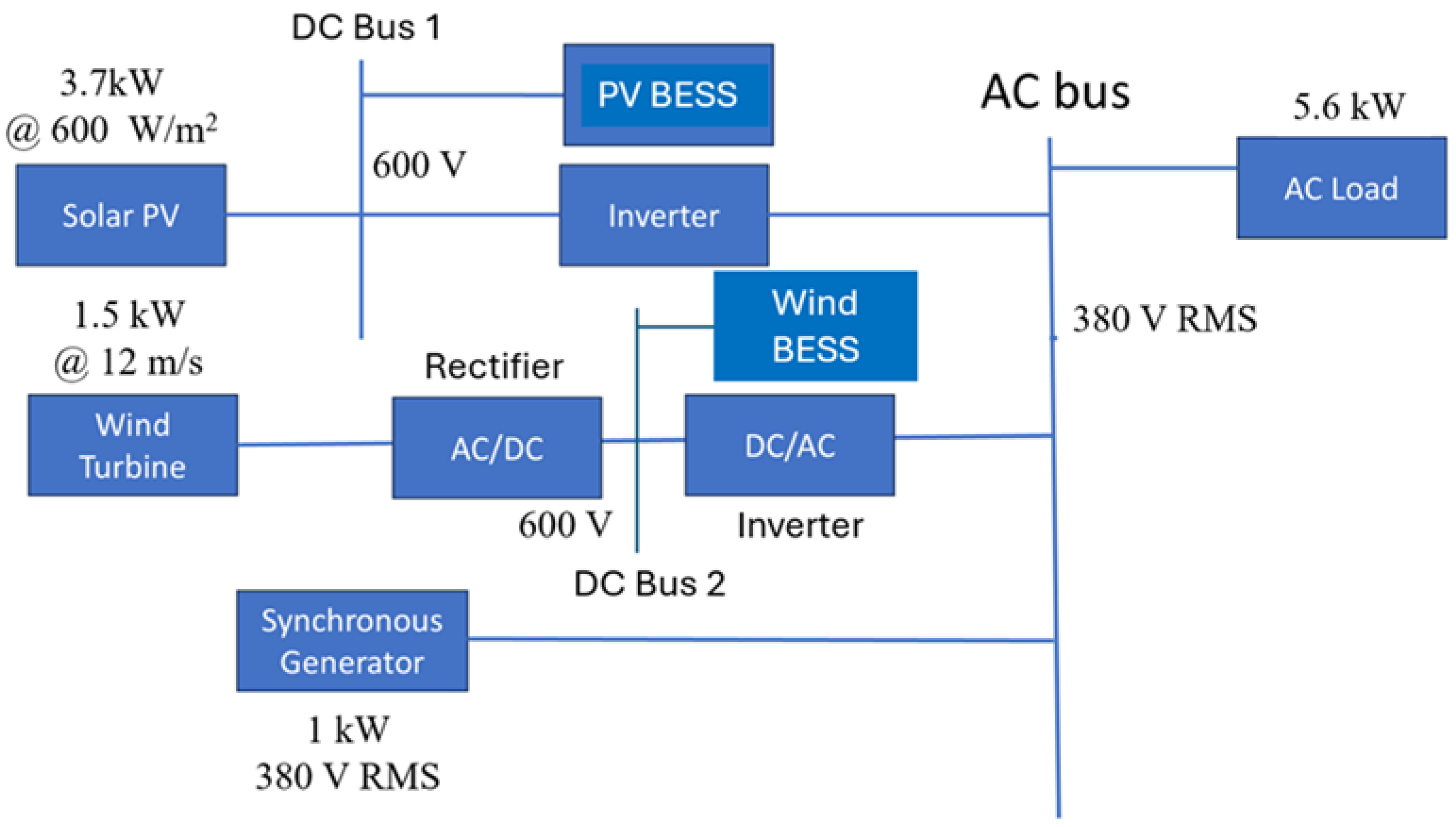
Figure 1. Hybrid AC Microgrid with Two BESSs.
Energies 17 06463 g001
Figure 2. Wind Speed Variation.
Energies 17 06463 g002
Figure 3. Varying Irradiance in PV Panel.
Energies 17 06463 g003
Figure 4. AC Bus Voltage During Varying Generation Conditions.
Energies 17 06463 g004
Figure 5. Duty Cycle of BESS Converter.
Energies 17 06463 g005
Figure 6. Cyberattack on BESS-Integrated Hybrid Microgrid System.
Energies 17 06463 g006
Figure 7. Impact of FDI Attack on PV-BESS Controller of Hybrid Microgrid System.
Energies 17 06463 g007
Figure 8. Impact of DoS Attack on PV-BESS Power Profile.
Energies 17 06463 g008
Figure 9. Solar DC Microgrid.
Energies 17 06463 g009
Figure 10. Grid-Connected Solar AC Microgrid.
Energies 17 06463 g010
Figure 11. Hybrid AC Microgrid with a single BESS.
Energies 17 06463 g011
Figure 12. Sigma-Delta Modulation (SDM) Controller.
Energies 17 06463 g012
Figure 13. Architecture of PI Controller.
Energies 17 06463 g013
Figure 14. Membership Function for Fuzzy Logic Controller Input.
Energies 17 06463 g014
Figure 15. Membership Function for Fuzzy Logic Controller Output.
Energies 17 06463 g015
Figure 16. DC Bus Power Comparison among three different controllers.
Energies 17 06463 g016
Figure 17. DC Bus Voltage Comparison among three different controllers.
Energies 17 06463 g017
Figure 18. BESS Power Comparison among three different controllers.
Energies 17 06463 g018
Figure 19. AC Load Power.
Energies 17 06463 g019
Figure 20. AC Bus RMS Voltage.
Energies 17 06463 g020
Figure 21. BESS Power comparison among three controllers.
Energies 17 06463 g021
Figure 22. AC Load Power.
Energies 17 06463 g022
Figure 23. Common AC Bus RMS Voltage.
Energies 17 06463 g023
Figure 24. PV_BESS Power in Hybrid Microgrid.
Energies 17 06463 g024
Figure 25. WIND_BESS Power in Hybrid Microgrid.
Energies 17 06463 g025
Figure 26. AC Load Power.
Energies 17 06463 g026
Figure 27. Common AC Bus RMS Voltage.
Energies 17 06463 g027
Figure 28. BESS Power for Single Battery at AC Bus.
Energies 17 06463 g028
Figure 29. Flowchart of Improved Ensemble Learning (SAMME AdaBoost) Method.
Energies 17 06463 g029
Figure 30. Confusion Matrix of SAMME AdaBoost Model for Detecting Cyberattacks.
Energies 17 06463 g030
Figure 31. Comparison between SAMME AdaBoost Model and Existing Ensemble Learning Model (AdaBoost) in “Class 0” Prediction.
Energies 17 06463 g031
Figure 32. Comparison between Ensemble Learning Model and SAMME AdaBoost Model in “Class 1” Prediction.
Energies 17 06463 g032
Figure 33. Comparison between Ensemble Learning Model and SAMME AdaBoost Model in “Class 2” Prediction.
Energies 17 06463 g033
Table 1. SDM Controller Design Parameters for Solar DC Microgrid.
Controller ParametersValues
Reference DC Power (Pref)3750 watts
Reference DC bus Voltage (Vref)400 volts
Integrator Gain (K)0.02
Feedback Loop Gain1
Comparator Threshold (Vth)−0.5 < e < 0.5
Clock Frequency (fs)100 kHz
Step Size0.01
Quantization Level3 levels (1, 0 and −1)
Table 2. SDM Controller Design Parameters for PV-Powered AC Microgrid.
Controller ParametersValues
Reference AC load Power (Pref)3750 watts
Reference DC bus Voltage (Vref)400 volts
Reference AC bus Voltage (Vrms)280 volts
Integrator Gain (K)0.01
Integrator Limit±100
Comparator Threshold1
Clock Frequency (fs)100 kHz
Step Size0.01
Quantization Level3 levels (1, 0 and −1)
Initial Duty cycle (D)0.5
Feedback Loop Gain1
Inverter Frequency60
Table 3. SDM Controller Design Parameters for Double BESS Hybrid Microgrid.
Controller ParametersBESS-1 (PV)BESS-2 (Wind)
Reference AC load Power (Pref)3750 watts1500 watts
Integrator Gain (K)0.0050.01
Integrator Limit±100±200
Comparator Threshold−0.5 < e < 0.5 −0.5 < e < 0.5
Clock Frequency (fs)100 kHz100 kHz
Step Size0.010.01
Quantization Level3 levels (1, 0 and −1)3 levels (1, 0 and −1)
Initial Duty cycle (D)0.50.5
Feedback Loop Gain11
Inverter Frequency60 Hz60 Hz
Table 4. SDM Controller Design Parameters for Single BESS Hybrid Microgrid.
Controller ParametersValues
Reference AC load Power (Pref)5600 watts
Reference AC bus Voltage (Vrms)380 volts
Integrator Gain (K)0.01
Integrator Limit±200
Comparator Threshold−0.5 < e < 0.5
Clock Frequency (fs)50 kHz
Step Size0.01
Quantization Level3 levels (1, 0 and −1)
Initial Duty Cycle (D)0.5
Feedback Loop Gain1
Inverter Frequency60 Hz
Table 5. PI Controller Design Parameters for Solar DC Microgrid.
Controller ParametersValues
Reference DC Power (Pref)3750 watts
Reference DC bus Voltage (Vref)400 volts
Stage 1: Integrator Gain (Ki)0.01
Stage 1: Proportional Gain (Kp)0.5
Stage 2: Integrator Gain (Ki)5
Stage 2: Proportional Gain (Kp)20
PWM Generator Frequency (fs)10 kHz
Table 6. PI Controller Design Parameters for PV-Powered AC Microgrid.
Controller ParametersValues
Reference DC Power (Pref)3750 watts
Reference DC bus Voltage (Vref)400 volts
Stage 1: Integrator Gain (Ki)0.1
Stage 1: Proportional Gain (Kp)1
Stage 2: Integrator Gain (Ki)2
Stage 2: Proportional Gain (Kp)3.5
PWM Generator Frequency (fs)10 kHz
Table 7. PI Controller Design Parameters for Double BESS Hybrid Microgrid.
Controller ParametersBESS-1 (PV)BESS-2 (Wind)
Reference DC Power (Pref)3750 watts1500 watts
Reference DC bus Voltage (Vref)400 volts400 volts
Stage 1: Integrator Gain (Ki)0.030.1
Stage 1: Proportional Gain (Kp)11
Stage 2: Integrator Gain (Ki)32
Stage 2: Proportional Gain (Kp)203.5
PWM Generator Frequency (fs)10 kHz10 kHz
Table 8. PI Controller Design Parameters for Single BESS Hybrid Microgrid.
Controller ParametersValues
Reference DC Power (Pref)5600 watts
Reference DC bus Voltage (Vref)380 volts
Stage 1: Integrator Gain (Ki)1
Stage 1: Proportional Gain (Kp)2.7
Stage 2: Integrator Gain (Ki)5
Stage 2: Proportional Gain (Kp)25
PWM Generator Frequency (fs)10 kHz
Table 9. Fuzzy Rule Table.
Fuzzy Input (ΔP)Fuzzy Output (D)
NSS
ZM
PSL
PBVL
Table 10. FLC Design Parameters for Solar DC Microgrid.
Controller InformationParameters
Input Error in power, ΔP
Output Duty Cycle, D
Input MFs4 nos: NS, Z, PS, PB (all triangular equispaced)
Output MFs4 nos: S, M, L, VL (all triangular equispaced)
Fuzzy Rule Base Mapping4 (NS-S, Z-M, PS-L, PB-VL)
Table 11. FLC Design Parameters for PV Powered AC Microgrid.
Controller
Information
Parameters
Input Error in power, ΔP
Output Duty Cycle, D
Input MFs4 nos: NS, Z, PS, PB (3 triangular equispaced, 1 trapezoidal)
Output MFs4nos: S, M, L, VL (all triangular but not equispaced)
Fuzzy Rule Base Mapping4 (NS-S, Z-M, PS-L, PB-VL)
Table 12. FLC Design Parameters for Double BESS Hybrid Microgrid.
Controller InformationBESS-1 (PV)BESS-2 (Wind)
Input Error in power, ΔPError in power, ΔP
Output Duty Cycle, DDuty Cycle, D
Input MFs4 nos: NS, Z, PS, PB
(2 triangular equispaced, 2 trapezoidal)
4 nos: NS, Z, PS, PB (3 triangular equispaced, 1 trapezoidal)
Output MFs4 nos: S, M, L, VL (all triangular but not equispaced)4 nos: S, M, L, VL (all triangular but not equispaced)
Fuzzy Rule
Base Mapping
4 (NS-S, Z-M, PS-L,
PB-VL)
4 (NS-S, Z-M, PS-L, PB-VL)
Table 13. FLC Design Parameters for Single BESS Hybrid Microgrid.
Controller InformationParameters
Input Error in power, ΔP
Output Duty Cycle, D
Input MFs4 nos: NS, Z, PS, PB
(3 gaussian equispaced, 1 bell shaped)
Output MFs4nos: S, M, L, VL
(all trapezoidal, but not equispaced)
Fuzzy Rule Base Mapping4 (NS-S, Z-M, PS-L, PB-VL)
Table 14. Performance Index for Solar DC Microgrid System.
IndexSDM
Controller
Fuzzy
Controller
PI
Controller
Without Controller
o T P b e s s d t = E B E S S (kJ)20.13 20.65 21.03 -
o T Δ V D C B U S d t (volt-sec)170.28201.96243.41901.77
Table 15. Performance Index for Grid Connected AC Microgrid System.
IndexSDM
Controller
Fuzzy
Controller
PI
Controller
Without Controller
o T P b e s s d t = E B E S S (kJ)20.13 20.65 21.03 -
o T Δ V A C B U S d t (volt-sec)255.28286.07301.711123.87
Table 16. Performance Index for Hybrid AC Microgrid System with Two BESS.
IndexSDM
Controller
Fuzzy
Controller
PI
Controller
Without Controller
o T P b e s s d t = E B E S S (kJ)17.03 17.25 17.33 -
o T P W T _ b e s s d t = E W T _ B E S S (kJ)12.20 12.56 12.83 -
o T Δ V D C B U S 1 d t (volt-sec)213.60353.09396.311548.3
o T Δ V D C B U S 2 d t (volt-sec)230.21398.36442.411611.88
o T Δ V A C B U S d t (volt-sec)141.76180.14220.85920.34
Table 17. Performance Index for Hybrid AC Microgrid System with Single BESS.
IndexSDM
Controller
Fuzzy
Controller
PI
Controller
Without Controller
o T P b e s s d t = E B E S S (kJ)20.77 22.8822.97 -
o T Δ V A C B U S d t (volt-sec)385.07398.45411.321823.27
Table 18. Comparison between AdaBoost and SAMME AdaBoost.
ParametersModelClass 0
Prediction
Class 1
Prediction
Class 2
Prediction
PrecisionSAMME0.950.940.96
AdaBoost0.920.920.96
RecallSAMME0.940.960.95
AdaBoost0.930.940.94
F1-ScoreSAMME0.950.940.95
AdaBoost0.920.930.94
Average AccuracySAMME0.9835
AdaBoost0.9657
Disclaimer/Publisher’s Note: The statements, opinions and data contained in all publications are solely those of the individual author(s) and contributor(s) and not of MDPI and/or the editor(s). MDPI and/or the editor(s) disclaim responsibility for any injury to people or property resulting from any ideas, methods, instructions or products referred to in the content.