Abstract
This manuscript discusses the advancements and historical development of solid oxide electrolysis (SOE), co-electrolysis, and methanation technologies, addressing the performance fundamentals and system integration challenges in the context of the EU’s 2050 climate neutrality goals. SOE technologies, characterized by their high efficiencies and ability to operate at elevated temperatures, offer significant advantages in hydrogen production and power generation. Co-electrolysis of steam and carbon dioxide in SOEs provides a promising pathway for syngas production, leveraging carbon capture and utilization strategies to mitigate carbon emissions. Additionally, catalytic methanation processes described within facilitate the synthesis of methane from carbon oxides and hydrogen, which could be integral to renewable energy storage and grid-balancing solutions. Historical analysis provides insights into the evolution of these technologies from early experiments to modern applications, including their role in space programmes and potential for industrial scale-up. The current state of research and commercialization, highlighted through various system designs and operational enhancements, suggests that SOEs are crucial for sustainable energy transformations, underscoring the necessity for continued innovation and deployment in relevant sectors.
1. Introduction
“The EU aims to be climate-neutral by 2050—an economy with net-zero greenhouse gas emissions. This objective is at the heart of the European Green Deal and in line with the EU’s commitment to global climate action under the Paris Agreement.” (https://climate.ec.europa.eu/eu-action/climate-strategies-targets/2050-long-term-strategy_en (accessed on 27 September 2024), 2021).
Global energy consumption was increasing with the world’s development (Figure 1a). Consequently, the emissions were also growing because of the primary energy source: fossil fuels (Figure 1b). Due to global worldwide challenges, like the world economic crisis in 2008–2099 and the COVID-19 pandemic in 2020, energy consumption fell (Figure 1), causing fewer emissions. But the global reduction to meet the goals of the Green Deal [1] and REPowerEU [2] is achievable only by the development and change of energy production technology.
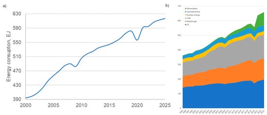
Figure 1.
Global energy consumption (a) in general and (b) by source (source: BP Energy Outlook 2023–2024).
To reach the goals, systems of carbon capture and storage (CCS), carbon capture and utilization (CCU), and carbon recycling and reuse (CRR) [3] should be implemented on a large scale, and the share of renewable energy systems (RESs) should continuously grow.
The energy generation from RESs has been rapidly increasing since 2006 (Figure 2).
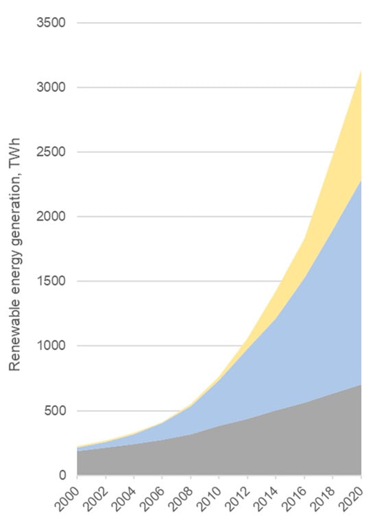
Figure 2.
Global renewable energy generation by source (source: BP Statistical Review of World Energy 2021, 70th edition).
Such rapid development and implementation of renewables, mainly solar and wind, has a major issue: the risk of imbalance between demand and production due to the intermittent character of renewables, which causes the necessity to implement technologies to use the excess electricity [4].
To tackle the issues of the Green Deal, REPowerEU plan, and RESs’ intermittent character, electrolysis technology could be crucial.
Electrolysis is an electrochemical method that splits water into hydrogen and oxygen by using electrical energy, such as surplus power generated from renewable energy sources (RESs). That process can take place in three main types of electrolysers: alkaline, proton exchange membrane (PEM), or solid oxide electrolysers. The SOE technology is one of the most efficient, with low energy demand (36–42 kWh/kg H2 [5,6]), high current/power density, and high gas purity.
The climate and decarbonization issues have increased interest in developing carbon capture, utilization, storage, and reuse technologies. Currently, the most developed and mainly used carbon capture technology is amine scrubbing. And the prospective further carbon utilization is the electrochemical conversion of CO2 or CO2 together with H2O [7,8,9,10,11,12].
The electrolysis of H2O and/or CO2 in SOE was firstly introduced by NASA in the late 1960s [13,14]. But attention only returned to that topic in the 1980s by [15,16,17], where the performance of the solid oxide electrolyser producing the hydrogen was analysed. Further, in the early 2000s, NASA investigated the methods of oxygen production via CO2 electrolysis [18,19], which brought the topic of H2O and/or CO2 to a high level of interest. Ebbesen [7,9,20,21,22] has provided numerous studies on the effective simultaneous reduction of CO2 and H2O in 2009–2012. The latest investigations in that field are mainly concentrated on material improvement [11], optimization of the system layout [23], and performance experiments [10,24].
2. SOE Fundamentals of Performance
The electrolyser considered in this study is the solid oxide electrolyser (SOE). Due to the usage of ceramic electrolyte, this type of electrolyser runs at high temperatures between 650 °C and 900 °C. The layers of a solid oxide cell are the cathode, the anode, and the electrolyte. YSZ (ZrO2 doped with 8 mol% Y2O3) for the electrolyte, nickel for the fuel electrode, and LSM (lanthanum strontium manganate) for the oxygen electrode are the most prevalent materials for SOE. Recent research results show that the materials face degradation challenges that impact their operational lifespan. Studies have reported degradation rates of approximately 0.75% to 1.4% voltage loss per 1000 h for cells operating between 750 °C and 850 °C. To mitigate these issues, advancements include the development of co-doped zirconia electrolytes, which enhance ionic conductivity and reduce degradation. Additionally, incorporating gadolinium-doped ceria (GDC) interlayers between the electrolyte and electrodes has been shown to improve chemical compatibility and suppress interfacial reactions, thereby extending cell longevity. Improved kinetics, thermodynamics favouring the utilization of internal heat at higher temperatures, and steam conversion all contribute to enhanced performance and allow for the attainment of high efficiencies in the 80–90% range [25,26,27,28,29].
The water steam is utilized and converted into hydrogen and oxygen in the SOE process. Steam enters the porous fuel electrode (cathode) and proceeds to the cathode–electrolyte interface, where it is reduced to H2 and oxygen ions. Hydrogen gas diffuses back via the cathode, whereas oxygen ions O= are conducted through the electrolyte. Oxygen ions are oxidized to generate pure oxygen gas at the contact between the electrolyte and anode. Figure 3 presents the described process. The reactions that occur on the cathode side and the anode side are given in Equations (1) and (2), respectively.
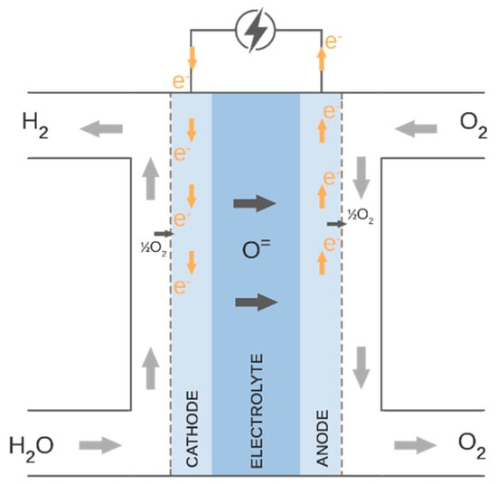
Figure 3.
Electrolysis process.
When comparing solid oxide electrolysis, co-electrolysis, and proton exchange membrane electrolysis technologies, it is essential to evaluate their differences in efficiency, cost, and scalability. SOE systems are highly efficient due to their operation at temperatures between 650 and 900 °C, which enhances their thermodynamic performance. This high operational temperature allows for the utilization of waste heat streams, boosting overall system efficiency to between 80 and 90%. Conversely, PEM electrolysers operate at lower temperatures (up to 80 °C) and typically achieve efficiencies of around 60–70%, although they benefit from rapid response times and can effectively balance the intermittent nature of renewable energy sources like wind and solar.
In terms of cost, SOE technologies generally require higher capital investment because they need materials that can withstand high temperatures, impacting both the initial setup and ongoing maintenance costs. PEM systems, while also reliant on costly catalysts such as platinum and iridium, avoid the need for the specialized materials required for high-temperature operations, making them less expensive in this regard, although the cost of catalysts remains a significant factor.
Scalability is another critical factor. SOE technologies face challenges in scaling due to the demands of high-temperature operation and the need for durable materials that maintain performance at larger scales. They are better suited for integration with industrial processes that can use the heat and hydrogen produced. PEM electrolysers, however, are more adaptable to various scales and can quickly adjust to power availability, making them ideal for fluctuating power supplies from renewable sources.
Choosing between SOE and PEM technologies often depends on specific needs such as the availability of heat sources, the capacity for capital investment, and the desired integration with other energy systems. While SOE and co-electrolysis provide superior efficiency with proper heat integration, PEM electrolysers offer more flexibility and scalability under varying operational conditions.
3. Co-SOE Fundamentals of Performance
The carbon-neutral, zero-emission, synthetic fuel can be produced via high-temperature co-electrolysis of H2O and CO2. Currently, there are two technologies able to perform co-electrolysis as a one-step process: solid oxide co-electrolysis and molten carbonate electrolysis [30]. Captured CO2 could be delivered with the steam to the solid oxide electrolyser and reduced to the H2 + CO gas mixture (syngas) utilizing electric power, e.g., from renewable energy sources. The schematic diagram of the process of co-electrolysis operation is shown in Figure 4. The overall reaction occurring inside the co-electrolyser is given in Equation (3).
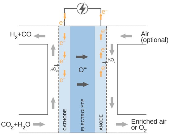
Figure 4.
Co-electrolysis process.
As presented in Figure 4, the carbon dioxide and steam are supplied to the cathode side of the co-electrolyser. At the cathode–electrolyte interface, the H2O and CO2 are reduced to H2 and CO, which diffuse back through the fuel electrode, and oxygen ions pass through the electrolyte and oxidize to oxygen or enrich the air supplied to the anode side of the electrolyser.
The electrochemical reactions of H2O and CO2 reduction on the cathode side are described in Equation (2) and (3). The oxidation reaction of the oxygen ions is given in Equations (4)–(6).
Depending on the operational temperature and catalyst used, syngas can be produced by electrochemical reduction of H2O and CO2 at a heterogeneous catalyst (e.g., nickel) or by means of electrochemical reduction of H2O to H2 followed by a homogeneous/heterogeneous [31,32,33,34,35,36] reverse water gas shift (RWGS) reaction [10,11], which occurs with a fast kinetic rate at the cathode side at high temperatures (above 720 °C [37]). The RWGS reaction is given by the following equation:
4. Methanation Reactor Fundamentals of Performance
Catalytic methanation, also known as the Sabatier reaction, involves the conversion of carbon oxides and hydrogen into methane. This reaction was first proposed and detailed by Paul Sabatier [38]. Various reactor designs are based on this principle, including the packed-bed Sabatier reactor, which is a type of heat exchanger, suggested by Sun D. and Simakov D. [39]. Other designs include the two-phase honeycomb reactor and the three-phase slurry bubble column reactor, both introduced by Held M. et al. [40].
Figure 5 illustrates a packed-bed Sabatier reactor of the heat exchanger type with cooling tubes containing flowing molten salt. According to Sun D. and Simakov D. [39], the proposed model presents a high CO2 conversion rate, good thermal management, and flexibility in catalyst installation and usage.
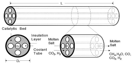
Figure 5.
Packed-bed Sabatier reactor.
The honeycomb reactor is a two-phase structured fixed-bed reactor. It is a multitube reactor with parallel tubes for the metallic catalyst carriers. The conversion of CO2 and H2 to CH4 occurs in the porous catalyst layer, and most of the reaction heat is released at the channel inlets [40].
A slurry bubble column reactor is a vertical cylinder in which three phases are in close contact: gaseous inlet (CO2 and H2) at the bottom of the column, the liquid product, and the solid catalyst. Using a specialized gas distributor at the bottom of the column, the gas phase is distributed into the liquid phase [41]. Heat management in that reactor type is presented by heat transfer fluid, which has a high heat capacity, allowing for effective heat transfer from the catalyst particles to the cooling medium in the cooling jacket [40].
A schematic drawing of the honeycomb reactor is shown in Figure 6a, and the slurry bubble reactor is presented in Figure 6b.
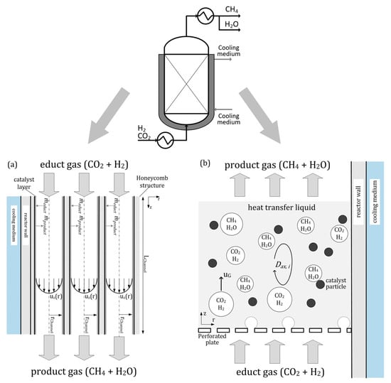
Figure 6.
Methanation reactors: (a) honeycomb type, (b) slurry bubble column type [40].
The honeycomb methanation reactor provides high specific CH4 production and excellent load flexibility. Comparing the two types of methanation reactors, the slurry bubble column reactor has a lower specific methane generation but a significantly better dynamic operation.
For the methanation process, catalysts based on Ni or Ru are required. Catalyst type, activity, and selectivity characteristics have the most influence on the process. Sabatier and Sendenders [38] discovered that nickel could catalyse the reaction between carbon oxides and hydrogen, which produces methane and water. For CO2 methanation, nickel supported on various metal oxides is the most frequent form of catalyst. The primary benefits are high activity, excellent CH4 selectivity, and low cost [42].
There are two prevalent processes for CO2 methanation:
- Without CO intermediate reaction.
- With CO intermediate reaction.
The first approach for the direct conversion of carbon dioxide to methane was proposed by Medsforth S. [43] and is characterized by the conversion chain shown below:
and further, that mechanism was developed by Pichler H. [44]. The proposed reactions of CO2 methanation are presented in Equations (8)–(11).
The second type of conversion consists of the first CO2 conversion to CO by the reversed water gas shift reaction (Equation (12)), followed by the conversion of CO to methane (Equations (13)–(16)). The reaction set, defined by Choe S.J. et al. [45], is presented below:
The equilibrium conditions for the methanation process are highly dependent on the reaction’s temperature and pressure. Due to the exothermic character of the reaction, as seen in Figure 7 [46,47], the methane generation rate generally decreases with increasing temperature and increases with increasing pressure. To maintain a high degree of conversion under ambient pressure, the temperature must be below 400 °C, but when pressure is increased, the practical temperature range expands (Figure 7). Numerous studies have analysed the optimal operating parameters for the methanation process. For example, one study [48] identifies the ideal conditions as a pressure range of 1 to 30 bar and a temperature between 200 °C and 300 °C. Another investigation [46] suggests that for systems combining solid oxide electrolysis (SOE) and a methanation reactor, the optimal parameters for effective CO2 utilization are around 40–60 bar and temperatures between 170 °C and 210 °C. Additionally, from a techno-economic perspective, the optimal pressure is found to be 20–30 bar with similar temperature conditions [49].
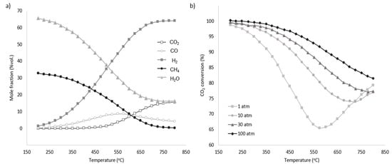
Figure 7.
(a) Equilibrium product factor for methanation at 1 atm. (b) Pressure influence on CO2 conversion for different temperatures [49].
Methanation reactors play a pivotal role in the production of synthetic methane, with different designs tailored to specific applications. The manuscript introduced three prominent reactor types. For industrial-scale methane production, packed-bed reactors are preferred due to their efficiency and thermal stability. In contrast, honeycomb reactors are better suited for grid-balancing applications, given their high productivity and adaptability to load variations. Slurry bubble column reactors, while less efficient in methane output, offer operational flexibility that aligns well with renewable energy systems.
The comparison (Table 1) underscores the need for careful reactor selection based on the intended application, highlighting the trade-offs between efficiency, operational challenges, and flexibility. Further research to optimize these designs for specific scenarios can enhance their utility across diverse energy systems.

Table 1.
Comparison of three methanation reactor technologies.
5. The Beginning of High-Temperature Electrolysis
The initial demonstration of water electrolysis was conducted in 1789 by Adriaan Paets van Troostwijk and Jan Rudolph Deiman, who used an electrostatic generator to create an electrostatic discharge between two gold electrodes submerged in water [50,51,52]. Subsequent improvements by Johann Wilhelm Ritter made use of Volta’s battery technology to facilitate the separation of product gases [53]. Dmitry Lachinov, in 1888, introduced an industrial method for the synthesis of hydrogen and oxygen through electrolysis, advocating for the use of alkaline solutions as electrolytes because they are less corrosive to iron electrodes than acidic solutions [54]. By 1902, more than 400 industrial water electrolysers were in use [55]. These early devices predominantly utilized aqueous alkaline solutions as their electrolytes. The technique of water electrolysis using a proton exchange membrane was first described in the 1960s by General Electric, originally developed to generate electricity for NASA’s Gemini Space Program, and was subsequently adapted to electrolysis for oxygen production.
The main historical points of electrolysis technology development are summarized in Table 2.
Table 2.
History of water electrolysis.
In 1900, Walther Hermann Nernst made a fundamental contribution to the development of the high-temperature–chemical thermodynamical relationship, which allowed for the calculation of a reduction potential of a reaction and the electrolyte YSZ, based on zirconium dioxide (ZrO2) stabilized by yttrium oxide (Y2O3) [68]. The groundwork for high-temperature electrolysers and batteries was laid. However, it was only in the 1960s that NASA began developing high-temperature electrolysers as part of its space programmes [56].
One of the earliest publications concerning the description of high-temperature electrolysis for hydrogen production as a “future energy carrier” was written by W. Doenitz et al. [15] in 1980. The requirements for electrolyser electrodes, electrolyte, and interconnecting material were described. The experiment of water steam electrolysis was also performed at operational conditions T = 900 °C and p = 20 bar. The obtained operational curve is presented in Figure 8.
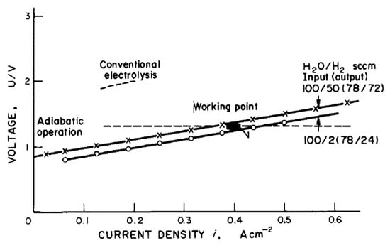
Figure 8.
Cell characteristics and working point of high-temperature electrolysis operation [15].
Also, the authors proposed to couple the electrolysis with the high-temperature reactor steam-generating process and, based on the HOT ELLY project [69], estimated the efficiency increase from 36–42% up to 44–51.5%.
Starting from the 1960s, NASA was developing the Advanced Life Support System, mainly for oxygen production from metabolically formed carbon dioxide and water [14,70,71,72,73]. The system consisted of twenty oxygen production stacks, six palladium tubes for hydrogen removal, a base plate, and housing (Figure 9). The approach to oxygen regeneration was developed by Westinghouse, and the idea was described by Elikan L. [13].
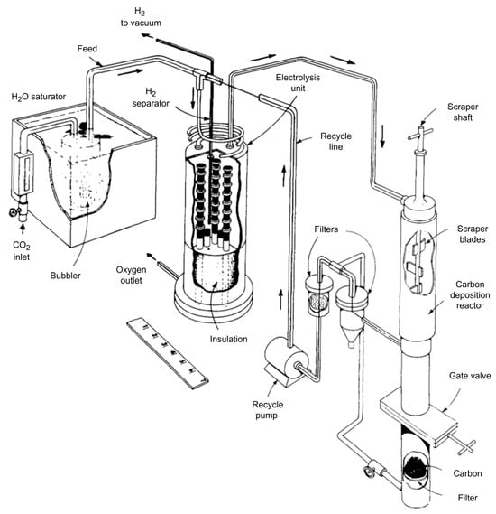
Figure 9.
NASA system for oxygen production.
High-temperature electrolysis could be a valuable solution for long-term missions for the human exploration of Mars, providing the in situ resource utilization (ISRU): the majority of CO2 in Mars’ atmosphere could be turned into propellant and life support consumables. The experimental studies of carbon dioxide electrolysis were provided by NASA and described by Tao G. [18,19].
Generally, the water steam and/or carbon dioxide high-temperature electrolysis began development as a technology for space programmes. However, further research and investigations showed that the high-temperature electrolysis is a promising solution for power and industrial sectors as the product is a syngas (H2 + CO). Research organizations from numerous nations and regions are performing studies focused on creating novel materials, improving the durability and performance of stacks, and lowering the cost of syngas production since the turn of the century.
6. Conclusions
This manuscript has comprehensively addressed the technological evolution and potential of solid oxide electrolysis (SOE), co-electrolysis, and methanation as pivotal technologies for advancing the EU’s climate neutrality objectives by 2050. Through historical analysis and detailed review of current technological capabilities, it is evident that SOE technologies, particularly when integrated with carbon capture and utilization strategies, offer a promising pathway for the decarbonization of the energy sector. The high efficiencies and capability of operating at elevated temperatures make SOEs particularly suitable for sustainable hydrogen production and power generation.
Co-electrolysis of steam and carbon dioxide has been highlighted as a significant advancement, facilitating syngas production that can be effectively integrated into existing industrial processes, thereby enhancing the versatility of renewable energy systems. The methanation process, catalytically converting carbon oxides and hydrogen into methane, provides a viable solution for energy storage and grid stabilization, which are critical for managing the intermittent nature of renewable energy sources.
The need for ongoing research and development is crucial, as evidenced by the discussion of system designs and operational enhancements that continue to push the boundaries of what is possible with SOE technologies. Future studies should focus on improving the durability and cost-effectiveness of these systems to facilitate wider adoption and implementation.
In conclusion, the integration of solid oxide electrolysis technologies within the renewable energy landscape represents a transformative approach towards achieving a sustainable and carbon-neutral energy future. However, integrating SOE/co-SOE and methanation systems with renewable energy sources like solar and wind faces challenges due to fluctuating power supply. The intermittency of renewable energy requires systems to operate flexibly under varying loads. SOE systems, though highly efficient, encounter thermal and mechanical stress from power variability, complicating the maintenance of their optimal operating temperatures (650–900 °C). Methanation reactors, reliant on the exothermic Sabatier reaction, are similarly sensitive to temperature fluctuations, risking reduced efficiency and catalyst deactivation. Effective integration demands robust energy and thermal storage solutions, hydrogen buffering, and advanced control systems for real-time synchronization. Addressing these challenges with material innovations and system optimization is crucial for reliable renewable energy coupling.
Funding
A part of research was funded by the Warsaw University of Technology within the Excellence Initiative: Research University (IDUB) programme (agreement nr 1820/92/Z01/2023). The authors are grateful for the research foundation of project WPC3/IMPRESSION/130/2023, supported by the National Centre for Research and Development (Poland) and the Ministry of Science and Technology (China).
Conflicts of Interest
The authors declare no conflict of interest.
References
- European Comission. A European Green Deal; European Comission: Brussels, Belgium, 2020. [Google Scholar]
- European Comission. REPowerEU Plan; European Comission: Brussels, Belgium, 2024. [Google Scholar]
- Braack, M.K.; Milewski, N.; Trappe, H. Crossing Social Boundaries in an Immigration Context: Exogamy and Gendered Employment Patterns in Unions in Germany. Gender Issues 2022, 39, 142–176. [Google Scholar] [CrossRef] [PubMed]
- Kupecki, J.; Motylinski, K.; Jagielski, S.; Wierzbicki, M.; Brouwer, J.; Naumovich, Y.; Skrzypkiewicz, M. Energy Analysis of a 10 KW-Class Power-to-Gas System Based on a Solid Oxide Electrolyzer (SOE). Energy Convers. Manag. 2019, 199, 111934. [Google Scholar] [CrossRef]
- Milewski, J.; Kupecki, J.; Szczęśniak, A.; Uzunow, N. Hydrogen Production in Solid Oxide Electrolyzers Coupled with Nuclear Reactors. Int. J. Hydrog. Energy 2020, 46, 35765–35776. [Google Scholar] [CrossRef]
- Eric, T.; Tony, W.; Casey, B.; Micah, C.; Michael, P.; Mark, R.; Randy, P. Solid Oxide Based Electrolysis and Stack Technology with Ultra-High Electrolysis Current Density (>3 A/Cm2) and Efficiency; A FuelCell Energy Company: Torrington, CT, USA, 2018. [Google Scholar]
- Ebbesen, S.D.; Graves, C.; Mogensen, M. Production of Synthetic Fuels by Co-Electrolysis of Steam and Carbon Dioxide. Int. J. Green Energy 2009, 6, 646–660. [Google Scholar] [CrossRef]
- Omojola, K. High Temperature Co Electrolysis of Carbon Dioxide and Steam in a Solid Oxide Cell for Synthesis Gas Production. Ph.D. Thesis, The University of Sheffield, Sheffield, UK, 2015. [Google Scholar]
- Chen, M.; Høgh, J.V.T.; Nielsen, J.U.; Bentzen, J.J.; Ebbesen, S.D.; Hendriksen, P.V. High Temperature Co-Electrolysis of Steam and CO2 in an SOC Stack: Performance and Durability. Fuel Cells 2013, 13, 638–645. [Google Scholar] [CrossRef]
- Wang, Y.; Liu, T.; Lei, L.; Chen, F. High Temperature Solid Oxide H2O/CO2 Co-Electrolysis for Syngas Production. Fuel Process. Technol. 2017, 161, 248–258. [Google Scholar] [CrossRef]
- Zheng, Y.; Wang, J.; Yu, B.; Zhang, W.; Chen, J.; Qiao, J.; Zhang, J. A Review of High Temperature Co-Electrolysis of H2O and CO2 to Produce Sustainable Fuels Using Solid Oxide Electrolysis Cells (SOECs): Advanced Materials and Technology. Chem. Soc. Rev. 2017, 46, 1427–1463. [Google Scholar] [CrossRef]
- Milewski, J.; Podhurska, V.; Martsinchyk, A.; Vasyliv, B.; Dybinski, O. Experimental and Theoretical Investigation of Contact Resistance in Molten Carbonate Fuel Cells. J. Power Sources 2023, 568, 232952. [Google Scholar] [CrossRef]
- Elikan, L.; Morris, J.P.; Wu, C.K. Development of a Solid Electrolyte Carbon Dioxide and Water Reduction System for Oxygen Recovery; NTRS: Chicago, IL, USA, 1972. [Google Scholar]
- Weissbart, J.; Smart, W.H. Study of Electrolytic Dissociation of CO2-H2O Using a Solid Oxide Electrolyte. NASA CR-680. In NASA Contractor Report; NASA CR: Washington, DC, USA, 1967; pp. 1–92. [Google Scholar]
- Doenitz, W.; Schmidberger, R.; Steinheil, E.; Streicher, R. Hydrogen Production by High Temperature Electrolysis of Water Vapour. Int. J. Hydrogen Energy 1980, 5, 55–63. [Google Scholar] [CrossRef]
- Dönitz, W.; Erdle, E. High-Temperature Electrolysis of Water Vapor—Status of Development and Perspectives for Application. Int. J. Hydrogen Energy 1985, 10, 291–295. [Google Scholar] [CrossRef]
- Isenberg, A. Energy Conversion via Solid Oxide Electrolyte Electrochemical Cells at High Temperatures. Solid State Ion. 1981, 3–4, 431–437. [Google Scholar] [CrossRef]
- Tao, G. Study of Carbon Dioxide Electrolysis at Electrode/Electrolyte Interface: Part I. Pt/YSZ Interface. Solid State Ion. 2004, 175, 615–619. [Google Scholar] [CrossRef]
- Tao, G. Study of Carbon Dioxide Electrolysis at Electrode/Electrolyte Interface: Part II. Pt-YSZ Cermet/YSZ Interface. Solid State Ion. 2004, 175, 621–624. [Google Scholar] [CrossRef]
- Ebbesen, S.D.; Høgh, J.; Nielsen, K.A.; Nielsen, J.U.; Mogensen, M. Durable SOC Stacks for Production of Hydrogen and Synthesis Gas by High Temperature Electrolysis. Int. J. Hydrogen Energy 2011, 36, 7363–7373. [Google Scholar] [CrossRef]
- Ebbesen, S.D.; Knibbe, R.; Mogensen, M. Co-Electrolysis of Steam and Carbon Dioxide in Solid Oxide Cells. J. Electrochem. Soc. 2012, 159, F482–F489. [Google Scholar] [CrossRef]
- Ebbesen, S.D.; Jensen, S.H.; Hauch, A.; Mogensen, M.B. High Temperature Electrolysis in Alkaline Cells, Solid Proton Conducting Cells, and Solid Oxide Cells. Chem. Rev. 2014, 114, 10697–10734. [Google Scholar] [CrossRef]
- Morgenthaler, S.; Kuckshinrichs, W.; Witthaut, D. Optimal System Layout and Locations for Fully Renewable High Temperature Co-Electrolysis. Appl. Energy 2020, 260, 114218. [Google Scholar] [CrossRef]
- Schreiber, A.; Peschel, A.; Hentschel, B.; Zapp, P. Life Cycle Assessment of Power-to-Syngas: Comparing High Temperature Co-Electrolysis and Steam Methane Reforming. Front. Energy Res. 2020, 8, 287. [Google Scholar] [CrossRef]
- Bocanegra-Bernal, M.H.; de la Torre, S.D. Phase Transitions in Zirconium Dioxide and Related Materials for High Performance Engineering Ceramics. J. Mater. Sci. 2002, 37, 4947–4971. [Google Scholar] [CrossRef]
- Laguna-Bercero, M.A. Recent Advances in High Temperature Electrolysis Using Solid Oxide Fuel Cells: A Review. J. Power Sources 2012, 203, 4–16. [Google Scholar] [CrossRef]
- Yue, X.; Yan, A.; Zhang, M.; Liu, L.; Dong, Y.; Cheng, M. Investigation on Scandium-Doped Manganate La0.8Sr0.2Mn1-XScxO3-Cathode for Intermediate Temperature Solid Oxide Fuel Cells. J. Power Sources 2008, 185, 691–697. [Google Scholar] [CrossRef]
- Ai, N.; Li, N.; He, S.; Cheng, Y.; Saunders, M.; Chen, K.; Zhang, T.; Jiang, S.P. Highly Active and Stable Er0.4Bi1.6O3 Decorated La0.76Sr0.19MnO3+δ Nanostructured Oxygen Electrodes for Reversible Solid Oxide Cells. J. Mater. Chem. A 2017, 5, 12149–12157. [Google Scholar] [CrossRef]
- Chauveau, F.; Mougin, J.; Bassat, J.M.; Mauvy, F.; Grenier, J.C. A new anode material for solid oxide electrolyser: The neodymium nickelate Nd2NiO4+δ. J. Power Sources 2010, 195, 744–749. [Google Scholar] [CrossRef]
- Martsinchyk, A.; Szczęśniak, A.; Martsinchyk, K.; Dybiński, O.; Cinti, G.; Milewski, J.; Shuhayeu, P.; Łazor, M.; Ćwieka, K.; Skibiński, J.; et al. Molten Carbonate Electrolyzer for Synthetic Fuel Generation. J. Power Sources 2025, 628, 235741. [Google Scholar] [CrossRef]
- Bustamante, F.; Enick, R.M.; Cugini, A.V.; Killmeyer, R.P.; Howard, B.H.; Rothenberger, K.S.; Ciocco, M.V.; Morreale, B.D.; Chattopadhyay, S.; Shi, S. High-Temperature Kinetics of the Homogeneous Reverse Water–Gas Shift Reaction. AIChE J. 2004, 50, 1028–1041. [Google Scholar] [CrossRef]
- Pekridis, G.; Kalimeri, K.; Kaklidis, N.; Vakouftsi, E.; Iliopoulou, E.F.; Athanasiou, C.; Marnellos, G.E. Study of the Reverse Water Gas Shift (RWGS) Reaction over Pt in a Solid Oxide Fuel Cell (SOFC) Operating under Open and Closed-Circuit Conditions. Catal. Today 2007, 127, 337–346. [Google Scholar] [CrossRef]
- Sun, Q.; Liu, C.-W.; Pan, W.; Zhu, Q.-M.; Deng, J.-F. In Situ IR Studies on the Mechanism of Methanol Synthesis over an Ultrafine Cu/ZnO/Al2O3 Catalyst. Appl. Catal. A Gen. 1998, 171, 301–308. [Google Scholar] [CrossRef]
- Zhao, K.; Bkour, Q.; Hou, X.; Kang, S.W.; Park, J.C.; Norton, M.G.; Yang, J.-I.; Ha, S. Reverse Water Gas Shift Reaction over CuFe/Al2O3 Catalyst in Solid Oxide Electrolysis Cell. Chem. Eng. J. 2018, 336, 20–27. [Google Scholar] [CrossRef]
- Wang, L.; Liu, H.; Liu, Y.; Chen, Y.; Yang, S. Effect of Precipitants on Ni-CeO2 Catalysts Prepared by a Co-Precipitation Method for the Reverse Water-Gas Shift Reaction. J. Rare Earths 2013, 31, 969–974. [Google Scholar] [CrossRef]
- Choi, S.; Sang, B.-I.; Hong, J.; Yoon, K.J.; Son, J.-W.; Lee, J.-H.; Kim, B.-K.; Kim, H. Catalytic Behavior of Metal Catalysts in High-Temperature RWGS Reaction: In-Situ FT-IR Experiments and First-Principles Calculations. Sci. Rep. 2017, 7, 41207. [Google Scholar] [CrossRef]
- Bogolowski, N.; Sánchez Batalla, B.; Shin, B.; Drillet, J.-F. Activity of La0.75Sr0.25Cr0.5Mn0.5O3−δ, Ni3Sn2 and Gd-doped CeO2 towards the reverse water-gas shift reaction and carburisation for a high-temperature H2O/CO2 co-electrolysis. RSC Adv. 2020, 10, 10285–10296. [Google Scholar] [CrossRef] [PubMed]
- Sabatier, P.; Senderens, J.B. New Methane Synthesis. C. R. Acad. Sci. Paris 1902, 134, 514–516. [Google Scholar]
- Sun, D.; Simakov, D.S.A. Thermal management of a Sabatier reactor for CO2 conversion into CH4: Simulation-based analysis. J. CO2 Util. 2017, 21, 368–382. [Google Scholar] [CrossRef]
- Held, M.; Schollenberger, D.; Sauerschell, S.; Bajohr, S.; Kolb, T. Power-to-Gas: CO2 Methanation Concepts for SNG Production at the Engler-Bunte-Institut. Chem. Ing. Tech. 2020, 92, 595–602. [Google Scholar] [CrossRef]
- Schweitzer, J.M.; Viguié, J.C. Reactor Modeling of a Slurry Bubble Column for Fischer-Tropsch Synthesis. Oil Gas Sci. Technol. Rev. L’IFP 2009, 64, 63–77. [Google Scholar] [CrossRef]
- Mebrahtu, C.; Krebs, F.; Abate, S.; Perathoner, S.; Centi, G.; Palkovits, R. CO2 Methanation: Principles and Challenges. In Studies in Surface Science and Catalysis; Elsevier: Amsterdam, The Netherlands, 2019; pp. 85–103. [Google Scholar]
- Medsforth, S. CLXIX.—Promotion of Catalytic Reactions. Part I. J. Chem. Soc. Trans. 1923, 123, 1452–1469. [Google Scholar] [CrossRef]
- Pichler, H. Accounting in Hydrogenation. 1943. Available online: https://www.osti.gov/biblio/6675880 (accessed on 15 September 2024).
- Choe, S.J.; Kang, H.J. Adsorbed Carbon Formation and Carbon Hydrogenation for CO2 Methanation on the Ni(111) Surface: ASED-MO Study. Korean Chem. Soc. 2005, 26, 1682–1688. [Google Scholar]
- Martsinchyk, A. Using MCFC for Capturing CO2 from Flue Gases and Delivering to Sabatier Reactor for SNG Synthesis; Institute of Heat Engineering (IHE): Warsaw, Poland, 2020. [Google Scholar]
- Jiajian, G.; Wang, Y.; Ping, Y.; Hu, D.; Xu, G.; Gu, F.; Su, F. A Thermodynamic Analysis of Methanation Reactions of Carbon Oxides for the Production of Synthetic Natural Gas. RSC Adv. 2012, 2, 2358–2368. [Google Scholar] [CrossRef]
- Stangeland, K.; Kalai, D.; Li, H.; Yu, Z. CO2 Methanation: The Effect of Catalysts and Reaction Conditions. Energy Procedia 2017, 105, 2022–2027. [Google Scholar] [CrossRef]
- Martsinchyk, K.; Martsinchyk, A.; Łazor, M.; Shuhayeu, P.; Kupecki, J.; Niemczyk, A.; Błesznowski, M.; Milewski, J. Feasibility Study and Techno-Economic Assessment of Power-to-Gas (P2G) Technology Based on Solid Oxide Electrolysis (SOE). J. Environ. Manag. 2024, 354, 120425. [Google Scholar] [CrossRef]
- Van Troostwijk, A.P.; Deiman, J.R. Sur Une Manière de Décomposer l’Eau En Air Inflammable et En Air Vital. Obs. Phys. 1789, 35, 369–378. [Google Scholar]
- Paets van Troostwijk, A.; Deiman, J.R. Über Die Zerlegungdes Wassers in Brennbare Und Lebensluft Durch Denelektrischen Funken. Ann. Phys. 1790, 2, 130–141. [Google Scholar]
- Troostwijk, P.A. Schets Der Nieuwe Ontdekkingenomtrent Het Water. Algem. Mag. Wetensch. Kunst Smaak 1790, 4, 909–941. [Google Scholar]
- Berg, H. Johann Wilhelm Ritter–The Founder of Scientific Electrochemistry. Rev. Polarogr. 2008, 54, 99–103. [Google Scholar] [CrossRef][Green Version]
- Zhang, J.; Zhang, L.; Liu, H.; Sun, A.; Liu, R.-S. Electrochemical Technologies for Energy Storage and Conversion, 2 Volume Set; John Wiley & Sons: Hoboken, NJ, USA, 2011; Volume 1, ISBN 3527328696. [Google Scholar]
- Kreuter, W.; Hofmann, H. Electrolysis: The Important Energy Transformer in a World of Sustainable Energy. Int. J. Hydrog. Energy 1998, 23, 661–666. [Google Scholar] [CrossRef]
- Péra, M.-C.; Hissel, D.; Gualous, H.; Turpin, C. Electrochemical Components; John Wiley & Sons, Inc.: Hoboken, NJ, USA, 2013. [Google Scholar]
- Katz, E. Electrochemical Contributions: William Nicholson (1753–1815). Electrochem. Sci. Adv. 2021, 1, e2160003. [Google Scholar] [CrossRef]
- de Levie, R. The Electrolysis of Water. J. Electroanal. Chem. 1999, 476, 92–93. [Google Scholar] [CrossRef]
- Faraday, M. On Electrical Decomposition. Philos. Trans. R. Soc. 1834, 124, 77–122. [Google Scholar] [CrossRef]
- Zhou, R.E. How to Offer the Optimal Demonstration of the Electrolysis of Water. J. Chem. Educ. 1996, 73, 786. [Google Scholar] [CrossRef]
- Hendricks, L.J.; Williams, J.T. Demonstration of Electrochemical Cell Properties by a Simple, Colorful Oxidation-Reduction Experiment. Chem. Educ. 1982, 59, 586–587. [Google Scholar] [CrossRef]
- Shakhashiri, B.Z. Chemical Demonstrations: A Handbook for Teachers of Chemistry; University of Wisconsin Press: Madison, WI, USA, 1992. [Google Scholar]
- Hugerat, M. New Inexpensive Apparatus for Electrolysis. Chem. Educ. J. 2008, 11, 11–19. [Google Scholar]
- Borja, A.N. Desarrollo de Un Sistema Modular de Reacción Para El Estudio de La Producción de Oxígeno e Hidrógeno a Partir de La Electrólisis Del Agua; Benemérita Universidad Autónoma de Puebla: Puebla, Mexico, 2018. [Google Scholar]
- Guillet, P.M.N. Hydrogen Production by Electrolysis; U.S. Department of Energy: Washington, DC, USA, 2015.
- Zdansky, E.A. Pressure Electrolyzers. U.S. Patent 2,717,872A, 19 September 1955. [Google Scholar]
- Ansar, A.S.; Gago, A.S.; Razmjooei, F.; Reißner, R.; Xu, Z.; Friedrich, K.A. Chapter 5-Alkaline Electrolysis—Status and Prospects. In Electrochemical Power Sources: Fundamentals, Systems, and Applications; Smolinka, T., Garche, J., Eds.; Elsevier: Amsterdam, The Netherlands, 2022; pp. 165–198. ISBN 978-0-12-819424-9. [Google Scholar]
- Funke, K. Solid State Ionics: From Michael Faraday to Green Energy-The European Dimension. Sci. Technol. Adv. Mater. 2013, 14, 43502. [Google Scholar] [CrossRef] [PubMed]
- Doenitz, W. Hydrogen Production with HOT ELLY. Dornier-Post 1977, 1, 17–19. [Google Scholar]
- Hamilton Standard Division of United Aircraft Corporation. Trade-off Study and Conceptual Design of Regenarative Advanced Life Support System (AILSS)-NASA-CR1458; NASA: Washington, DC, USA, 1970.
- Elikan, L.; Morris, J.P. Solid Electrolyte System for Oxygen Regeneration. NASA CR-1359; NASA: Washington, DC, USA, 1969.
- Weissbart, J.; Smart, W.H. A Two-Cell 8-Ampere CO2-H2O Solid Electrolyte Electrolyzer for Oxygen Production; National Aeronautics and Space Administration AMES Research Center: Moffett Field, CA, USA, 1970. [Google Scholar]
- Smart, W.; Weissbar, J. A 127-Ampere CO2-H2O Solid Oxide Electrolyzer-Reactor System For Production of Oxygen; Electrochemical Soc Inc.: Pennington, NJ, USA, 1970. [Google Scholar]


Disclaimer/Publisher’s Note: The statements, opinions and data contained in all publications are solely those of the individual author(s) and contributor(s) and not of MDPI and/or the editor(s). MDPI and/or the editor(s) disclaim responsibility for any injury to people or property resulting from any ideas, methods, instructions or products referred to in the content. |
© 2024 by the authors. Licensee MDPI, Basel, Switzerland. This article is an open access article distributed under the terms and conditions of the Creative Commons Attribution (CC BY) license (https://creativecommons.org/licenses/by/4.0/).