Article

Pressurized Chemical Looping for Direct Reduced Iron Production: Economics of Carbon Neutral Process Configurations

Natural Resources Canada, CanmetENERGY-Ottawa, Ottawa, ON K1A 1M1, Canada
*
Author to whom correspondence should be addressed.
Energies 2024, 17(3), 545; https://doi.org/10.3390/en17030545
Submission received: 18 December 2023 / Revised: 17 January 2024 / Accepted: 19 January 2024 / Published: 23 January 2024

Abstract

:
The replacement of the blast furnace—basic oxygen furnace (BF-BOF) steelmaking route with the direct reduced iron—electric arc furnace (DRI-EAF) route reduces the direct CO2 emissions from steelmaking by up to 68%; however, the DRI shaft furnace is one of the largest remaining point source emitters in steelmaking. The capital and operating expenses of two potential nearly carbon-neutral DRI process configurations were investigated as a modification to a standard Midrex DRI facility. First, amine-based post-combustion capture with a 95% capture rate was considered as the benchmark, as it is currently commercially available. A second, novel configuration integrated the Midrex process with pressurized chemical looping—direct reduced iron (PCL-DRI) production. The capital expenditures were 71% and 28% higher than the standard Midrex process for a Midrex + amine capture plant, and a PCL-DRI plant, respectively. There was an incremental variable operating cost of USD 103 and USD 44 per tonne of CO2 for DRI production using amine capture and PCL-DRI, respectively. The amine capture configuration is most sensitive to the cost of steam generation, while PCL-DRI is more sensitive to the cost of electricity and the makeup oxygen carrier. An iron-based natural ore is recommended for PCL-DRI due to the low cost and availability. Based on the lower costs compared to amine-based post-combustion capture, PCL-DRI is an attractive means of eliminating CO2 emissions from DRI production.

1. Introduction

1.1. Background

Globally, the 1.9 Gtonnes per year of iron and steel produced results in 2.6 Gtonnes of CO2 emissions, with the demand for steel projected to increase by a third by 2050 [1]. Steel producers are beginning to take actions to reduce those emissions, including in Canada, where they have committed to net zero steel by 2050 and have initiated capital expenditures to achieve substantial reductions by 2030 [2,3]. One such way of achieving those emissions reduction targets is to replace the blast furnace and basic oxygen furnace (BF-BOF) in the integrated steel mill with direct reduced iron (DRI) production followed by an electric arc furnace (EAF). This transition can reduce the emissions from steelmaking by up to 68% [4,5]. The DRI plant is one of the remaining large point source contributors to CO2 emissions from iron and steelmaking, since the heat for the process is conventionally supplied via the combustion of fossil fuels.
Midrex is the technology provider that currently possesses the largest market share of operational DRI plants globally [6]. For this reason, the process configurations in this work are considered as modifications to, and are compared against, the standard Midrex process. The means of achieving carbon neutrality are limited to carbon capture in the scope of this work, though other researchers are considering other routes to eliminate CO2 emissions. For example, Midrex is developing Midrex-H2, and other researchers are developing their equivalents, which use hydrogen instead of natural gas-derived syngas as the reductant for the iron ore in the shaft furnace [4,7]. Hydrogen is an attractive option if the infrastructure becomes available to support it; however, in many parts of the world, access to low-cost, low-emission hydrogen is a barrier to current implementation. It also changes the heat balance of the shaft furnace, as the reduction becomes endothermic instead of exothermic and reduces the carbon content in the DRI product, which is essential for efficiency in the downstream EAF [8]. Another means of attaining carbon neutral DRI is through the use of biofuels to create bio-syngas for use as the reductant, though securing sufficient biomass supply may be a challenge in some geographic locations, as it is being considered as a solution in a variety of industries [9].
Another DRI technology provider, Energiron, has developed a “zero reformer” process that operates in a similar way to the conventional Midrex process used for this work, except that the reforming reactions occur within the shaft furnace itself instead of in a separate process unit. The fuel type is flexible, including natural gas, bio-syngas, hydrogen, and off-gases from other iron and steelmaking process units. This has the advantage of increasing the process efficiency and reducing the equipment footprint. A portion (approximately 60%) of the CO2 produced is removed and captured by an amine plant [10]. While there is no longer a reformer fired with the fossil fuel-derived top gas, depending on the specific configuration and application, there are still substantial CO2 emissions from the zero reformer configuration. A process gas heater, typically fired with recycled top gas or other fossil-derived fuels, is required to increase the temperature of the cooled recycled top gas stream from the amine plant and cool makeup natural gas to the required furnace inlet temperature (approximately 900–1000 °C).
Chemical looping is an energy conversion technology that inherently separates CO2 from flue gas upon the combustion of a fuel, without the need for an air separation unit, for easy and efficient carbon capture [11]. Unlike amine-based CO2 capture, which requires additional large equipment be installed to separate CO2 from the flue gas, chemical looping reactors directly replace the units used to supply process heat. When performed at elevated pressures, it is referred to as pressurized chemical looping (PCL). The pressurization of chemical looping has many advantages, including reduced equipment size and plant footprint, reduced capital cost, increased reaction rates, increased heat transfer rates, and enhanced latent heat recovery [12]. In one variant using fluidized beds, chemical looping requires two reactors (air and fuel), which are typically housed in separate process vessels. The bed material transferred between the reactors is an oxygen carrier comprised of metals at different oxidation states. In the air reactor, air is used as the fluidizing gas. The oxygen carrier is oxidized, releasing heat that is used to achieve the desired objective (reforming, steam production, etc.). The oxygen-depleted air (herein referred to as “vitiated air”) is vented without CO2 emissions. The oxidized oxygen carrier is then passed to the fuel reactor, where, provided there is sufficient oxygen, it reacts with the fuel to produce CO2 and water via a solid state or homogenous reaction [13,14]. After the cooling and conditioning of the flue gas to remove the majority of the water, the captured CO2 stream is sent to a compression and drying unit to prepare it for transportation and storage or utilization.
In this work, the economics of applying PCL technology within a Midrex-type DRI plant are investigated in comparison to the original Midrex process, as well as in comparison to existing commercially available post-combustion carbon capture technology. This builds on previous work by Bond et al., in which the process performance for these configurations was quantified [15,16].

1.2. Process Description
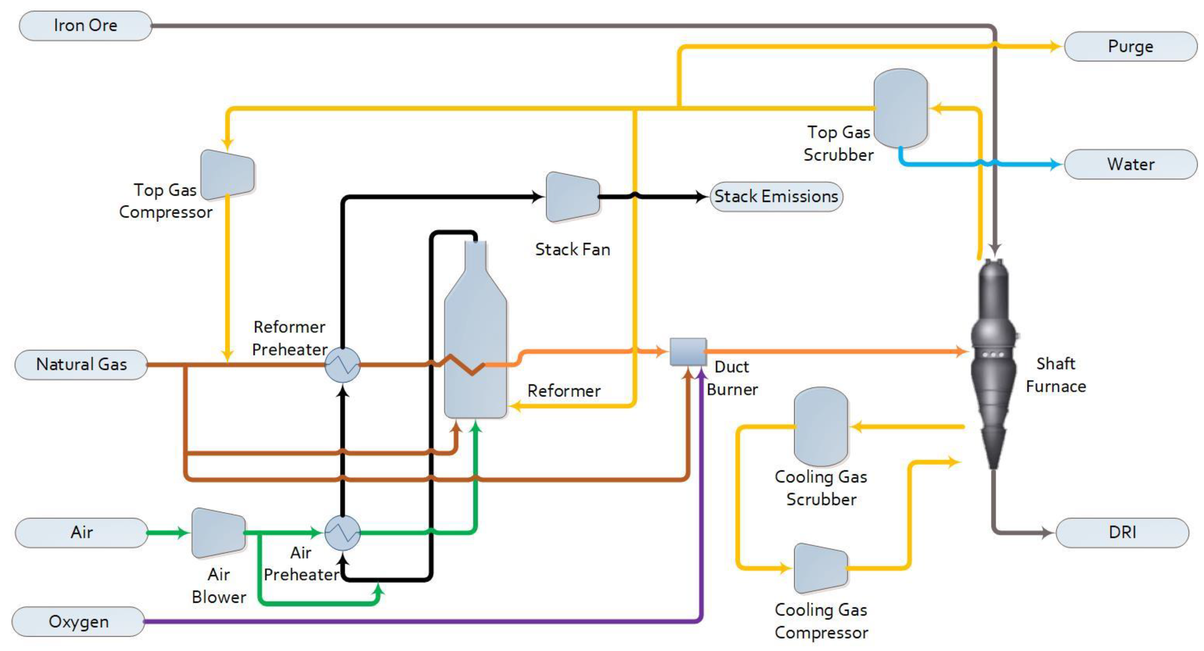
The DRI plant considered in this work has an annual DRI production rate of 2 Mtonnes to be homologous to the scale of the Voestalpine Midrex plant constructed in Texas [17]. The plant evaluated here is assumed to be operational for 7998 h per year to align with current Midrex performance guarantees [18]. Three process configurations were explored: a base case that consists of a standard Midrex DRI configuration, the application of amine absorption to the flue gas from the base case (Base Case + PCC) to achieve 95% capture, and the integration of PCL to replace the reformer of the Midrex process while simultaneously capturing CO2 (PCL-DRI). The latter two cases are nearly carbon neutral (hereafter denoted as carbon neutral for brevity), while all CO2 from the base case is vented to the stack.

1.2.1. Base Case

The configuration and performance of the base case Midrex process has already been discussed in detail in previous work, where it was denoted as Base-M [15]. Figure 1 shows the major equipment in this process, all of which are included in the scope of the economic analysis. In short, the process consists of a shaft furnace, a reformer, and supporting equipment for the treatment of the recycled top gas and the preheating of feed gases. The inputs to the shaft furnace are the iron ore, provided as DRI-grade pellets, and a hot reducing gas consisting of a mixture of CO, H2, CH4, CO2, H2O, and N2. Through contact with this gas, the majority of the iron in the pellets is reduced to metallic iron, with a lesser fraction remaining as FeO. Downstream processing in the EAF melts down and refines this product into steel [18,19]. Cooling gas at the cone of the furnace controls the final product temperature. The size, cost, and performance of the shaft furnace is kept constant across all configurations studied in this work.
The reformer is fed natural gas and recycled top gas and produces the syngas used as the reducing gas in the shaft furnace after additional heating in a duct burner. Dry reforming reactions dominate in the Midrex reformer [20]. The syngas outlet temperature (925 °C), pressure (220 kPa(a)), and composition [6,21] are kept constant across all configurations. The flue gas from the reformer firebox is the source of all the CO2 emissions from this process.
Though not shown in Figure 1 for simplicity, solids handling equipment for the iron ore feed to the shaft furnace are also included in the scope of the plant costs evaluated here. This equipment consists of a storage silo, bucket elevator, surge bin, swing hopper, and injection hopper.

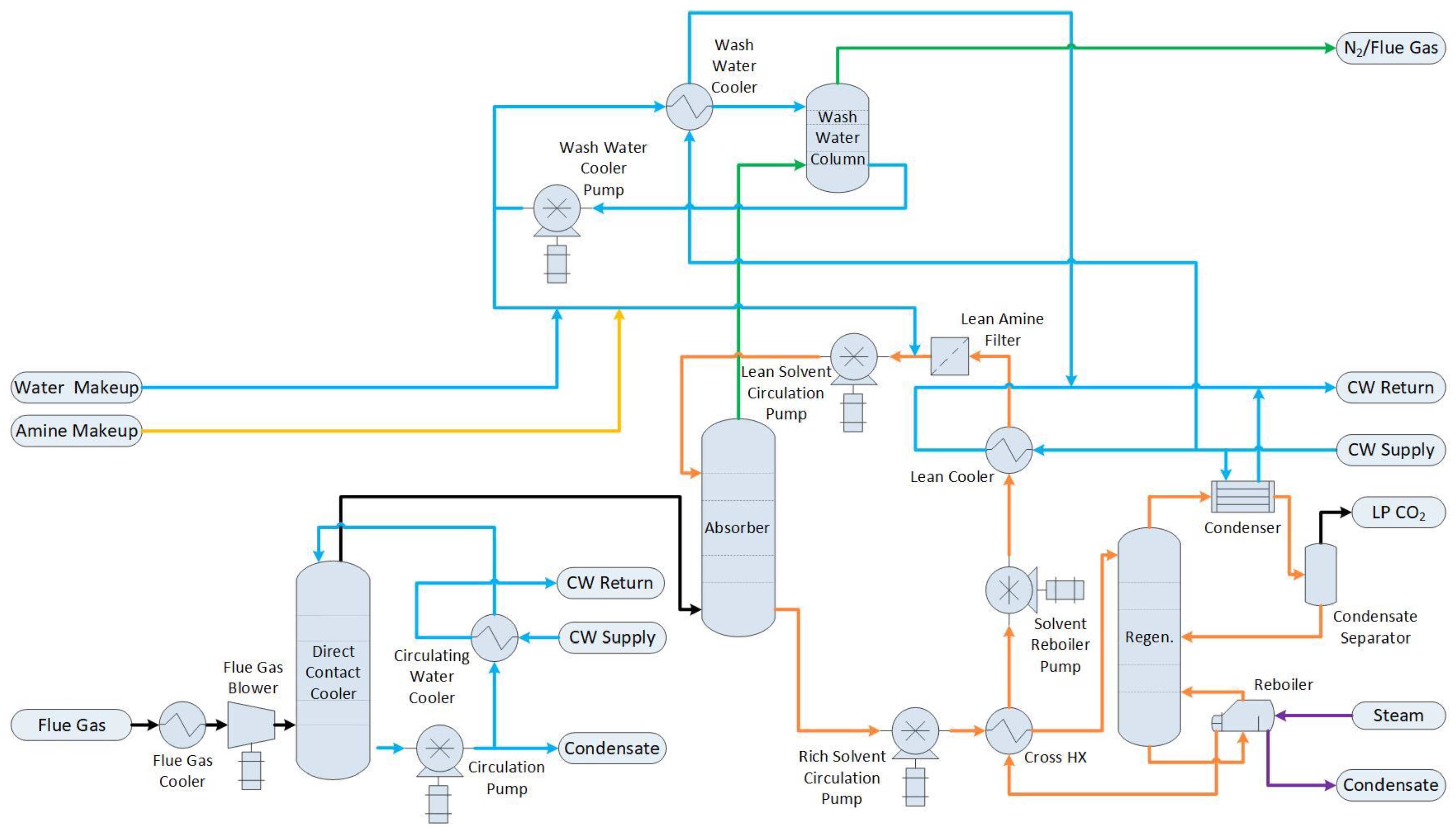
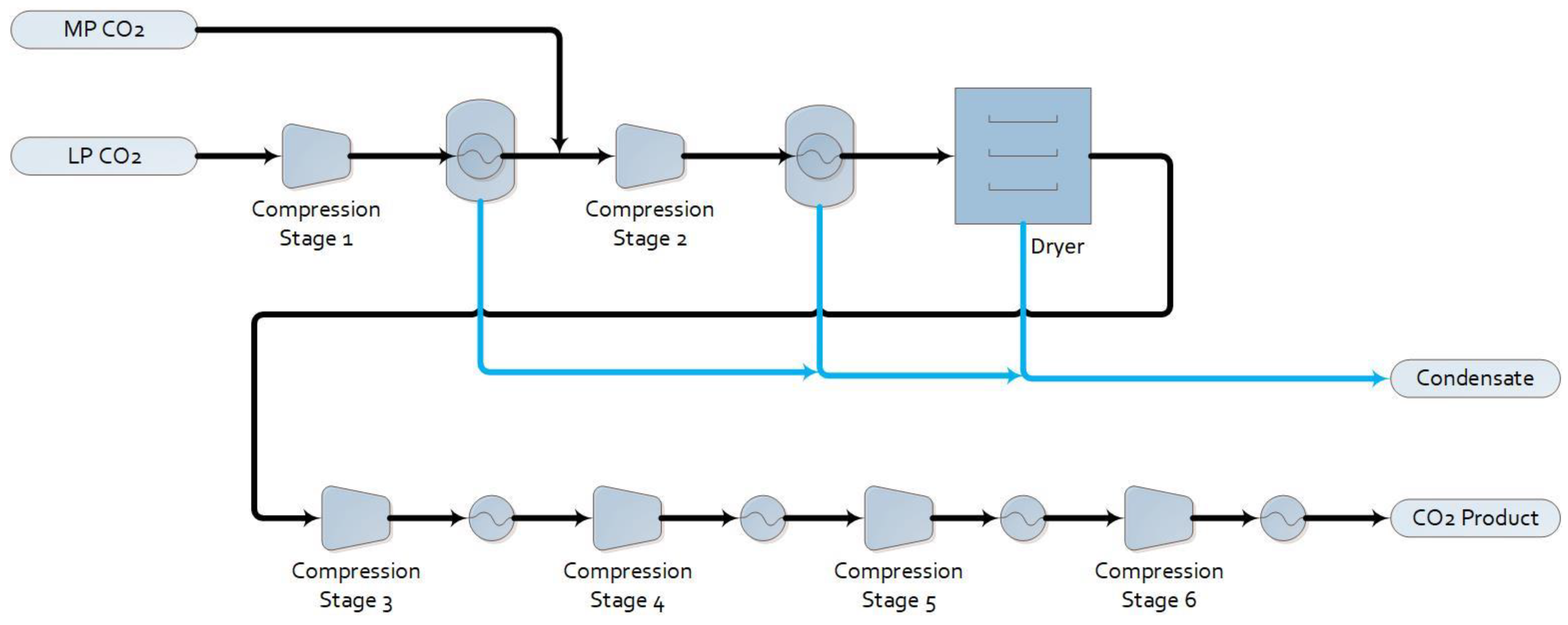
1.2.2. Base Case with Post-Combustion Capture (Base Case + PCC)

The performance of amine post-combustion capture as applied to a Midrex DRI plant has been explored previously by Bond et al. [16]. For an explanation of the principles of amine processes, readers are referred to the work by Agbonghae et al. [22]. For this configuration, the base case plant shown in Figure 1 is identical, apart from the removal of the stack fan. The flue gas stream from the reformer firebox is directed to the equipment shown in Figure 2. First, it passes through a flue gas cooler and blower, and then it is further cooled and conditioned in a direct contact cooler (DCC). Heat is removed from the DCC’s recirculating water using cooling water in a compact heat exchanger. The removal of the CO2 from the flue gas is achieved in a packed column absorption tower using MEA as the solvent. The depleted flue gas stream, consisting primarily of N2, is scrubbed of residual amine in a wash water column before being vented to the atmosphere. The CO2-rich solvent is heated in the cross-heat exchanger and sent to the regeneration column, where it is heated to extract the CO2 as a pure, low-pressure stream from the top of the column. Substantial steam input is required to the reboiler of the regenerator to achieve this separation.
The low-pressure CO2 product from the amine system is sent to a standard CO2 compression and drying package, as shown in Figure 3. The CO2 compressor has six stages, with intercooling. Water knockout after the first two compression stages followed by a dryer removes moisture to meet the specification for the Alberta Carbon Trunk Line [23].

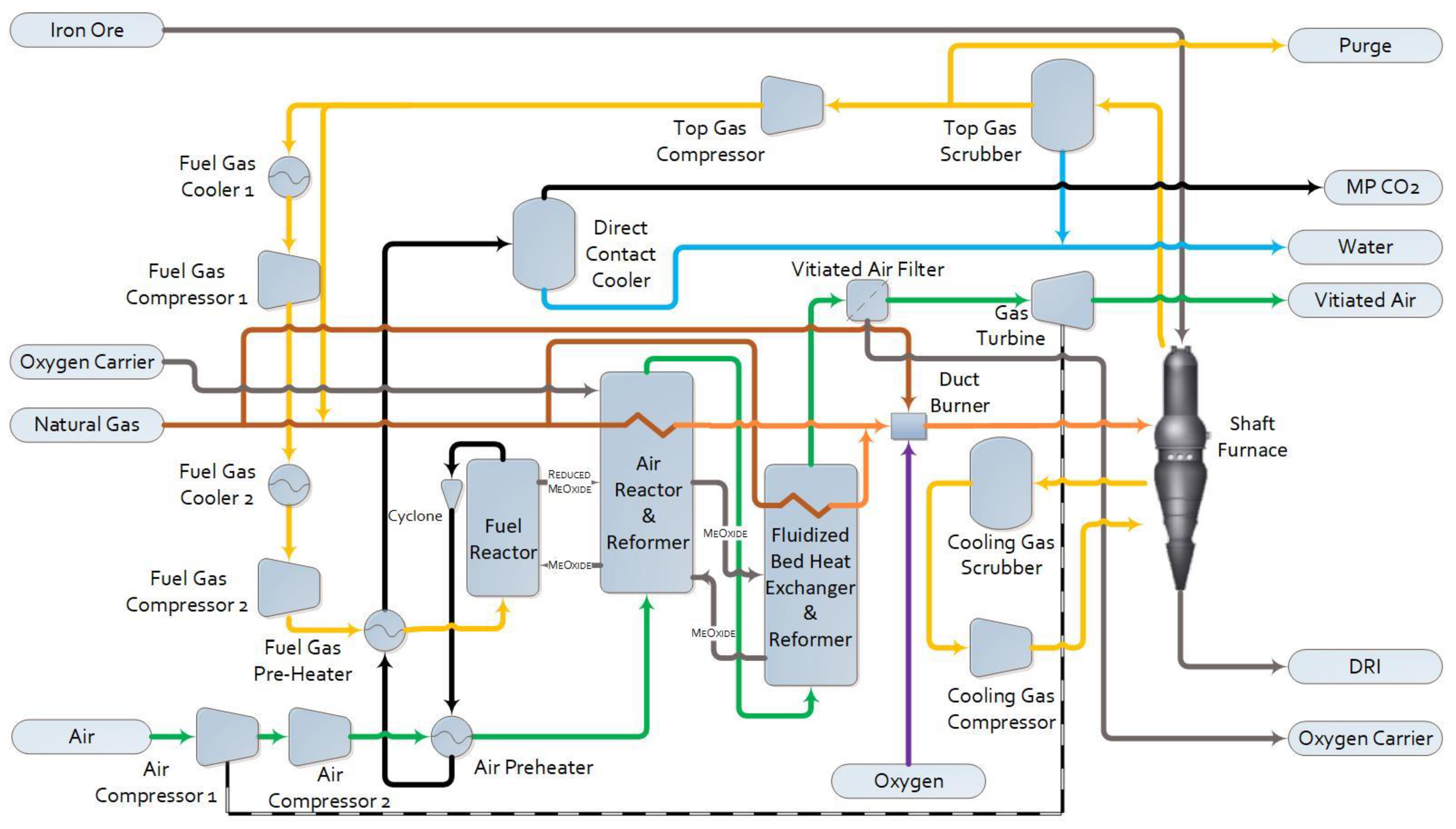
1.2.3. Pressurized Chemical Looping DRI (PCL-DRI)

The configuration and performance of a Midrex DRI plant integrated with PCL has already been discussed in detail in previous work, where it was denoted as PCL-DRI-M [15]. In this configuration, the reformer firebox is replaced with parallel PCL reactors. As a modification to the previous work, external fluidized bed heat exchangers are added here in sequence with the air reactors to provide a sufficient heat transfer area, as shown in Figure 4. The reformer tubes are placed in the bed portion of the air reactor, where most of the heat from combustion is released, and in the beds of the connected fluidized bed heat exchangers. Equipment is added to recover heat and remove entrained solids from the concentrated flue gas and vitiated air flowing from the fuel and air reactors, respectively. Considering the flue gas exiting the fuel reactor, bulk solid removal is achieved with cyclones. The remainder of the fine particulate matter is removed using a DCC. The cooled flue gas is then sent to the second stage of the CO2 compression and drying package shown in Figure 3. Considering the vitiated air exiting the air reactor, the temperature of the vitiated air exiting the fluidized bed heat exchanger is reduced significantly through the heat removal to the reformer tubes, allowing the majority of solids to disengage before they exit the vessel, since the up-flowing gas velocity in the reactor drops below the transport velocity of the solids. The remainder of the particulate matter is removed via a candle filter before the gas is sent to a turbine for power recovery to help drive the main air compressors. Not shown in Figure 4 for simplicity, but included within the assessment, are the solid storage and handling equipment for both charging the shaft furnace with the pelletized iron ore feed (DR pellets) and performing oxygen carrier makeup to the PCL reactors.
The traditional arrangement of a chemical looping reactor consists of two separate process vessels: one housing the air reactor and one housing the fuel reactor. Solids are transferred between the vessels using external solids transfer legs and non-mechanical seals, such as loop seals [24]. This type of arrangement often has challenges in reliability due to the external solids transfer legs, especially at elevated pressures, and requires a larger footprint. To overcome these challenges, in this work, the reactor design is inspired by Chalmers University’s 300 W chemical looping test unit, incorporating both reactors into a single vessel [25]. Chalmers’ reactor operated at near-atmospheric pressure, while the authors here adapt the design for pressurized operation, using ilmenite as the oxygen carrier. Ilmenite, consisting ideally of FeTiO3 (FeO·TiO2), is a naturally occurring ore that is readily available at low cost [26,27]. It is used directly after crushing; unlike with the feed to the shaft furnace, pelletization is not required.
This reactor, shown in Figure 5, operates with the fuel reactor in bubbling mode, fluidized by the recycled top gas from the shaft furnace that is used as fuel. Due to efficiency gains from the enhanced heat transfer in fluidized beds compared to radiant heat transfer in traditional reformer furnaces, the reactors are able to operate at a lower temperature than the Midrex reformer and thus require less fuel input to the fuel reactor [15]. The reduced oxygen carrier is transferred from the fuel reactor to the adjacent air reactor through an internal loop seal that sits beneath both beds. The air reactor is fluidized with air and operates as a circulating fluidized bed. The oxidized oxygen carrier is transported to the top of the reactor, to a disengagement zone, which causes the solids to drop down into the upper loop seal. Passage through this loop seal returns the oxygen carrier back to the fuel reactor, completing the loop [25]. For PCL-DRI, both loop seals are fluidized with steam generated using waste heat from the hot flue gases, and the reformer tubes are inserted into the bed of the air reactor.
This compact reactor design, detailed in Table 1, was selected to reduce the capital costs, minimize the footprint, and improve the operability and reliability of the PCL system. A size constraint of 8 m in diameter was used for the PCL reactor vessel to ensure the practicality of fabrication, transportation, and mechanical support of the vessel; identical parallel trains allow the system to be scaled up to any capacity in a modular fashion. The operating pressure was selected based on the optimal range of 500–800 kPa(a) identified when applying PCL to a different application [12]. The upper limit of this range was used to enhance heat transfer. The operating conditions of the PCL reactors in this case were updated after the previous work [15,16] to address challenges relating to fitting the reformer tube bundles in the reactor. At an air reactor temperature of 950 °C, the required surface area of the reformer tubes was too large to reasonably fit within the available reactor volume. The air and fuel reactor operating temperatures have been increased to 1050 °C for this work, which is the upper limit for fluidized bed operations with ilmenite ore to avoid sintering or agglomeration [28]. The reformer heat transfer area per reactor was determined using tubes with a 0.12 m outer diameter and a pitch of 0.25 m. To accommodate the required size of the reformer, two external fluidized bed heat exchangers were employed alongside the four parallel PCL reactor systems to expand the effective size of the air reactor. The sizing of these external fluidized bed heat exchangers is given in Table 2.

2. Methods

2.1. Process Simulation

Process simulations for all cases were created in ASPEN HYSYS v14 using the Peng-Robinson fluid package for all process operations, with the exception of those concerning the amine solvent and steam for regeneration of the amine. For amine solvent operations, the Converted DBR Amine Package (v7.3) was used. The NBS Steam package was used for the steam streams. Details of the process simulation boundaries and operating conditions are described by Bond et al. [15]. Simulations were used to determine equipment capacities and flow rates of the utility, raw material, and waste streams.

2.2. Capital Cost

The complete capital cost for each case was determined so that the relative increase in costs associated with carbon neutral configurations could be assessed relative to a typical commercial DRI plant. All costs assume installation at the US Gulf coast or a similar location (i.e., no location cost factor applied). The selected methods generate a Class 4 cost estimate with an accuracy of −30% to +50%.
Purchased equipment costs for all common equipment types were determined using the costing method developed by Seider et al. [30], with the exception of pumps, for which the Turton et al. correlation was simpler to integrate with the process simulation [31]. Several pieces of equipment were not available in the Seider or Turton correlations and required input from other sources. The PCL reactors and external fluidized bed heat exchangers were costed as Seider pressure vessels, with added costs for refractory as per commercial vendor quotes, internal metal components, and reformer heat transfer tubes. The shaft furnace and duct burner were costed as a brick-lined gravity shaft furnace and an incinerator, respectively, using correlations from Ulrich [32]. The candle filter was costed as a Seider pressure vessel, with added costs for the internal filter elements as per commercial vendor quotes. Finally, the cyclones were costed as Seider cyclones placed within a refractory-lined Seider pressure vessel, with multiple cyclones housed within a single pressure vessel. The detailed breakdown of cost formulas applied for each process unit is given in the Supplementary Data (Table S1).
Each element of the total capital investment was estimated using a factored approach based on the purchased equipment cost (PE), as shown in Table 3. The choice of factors was based on ranges provided by Peters et al. [33] in combination with industrial experience. All calculated costs were adjusted to a basis of USD, 2022 using the Chemical Engineering Plant Cost Indexes (CEPCI).

2.3. Operating Costs

Hourly consumption rates of raw materials, utilities and waste treatment facilities were determined for each case based on the process simulations. Annual costs were calculated using the unit costs provided in Table 4 and a yearly operating time of 7998 h. These costs comprise the variable operating costs for the plant.

3. Results

3.1. Capital Cost

The total capital investment for the construction of a standard MIDREX DRI plant (the base case) is compared to two carbon neutral DRI process configurations in Table 5. Applying amine post-combustion capture to the flue gas from the reformer in the base case plant (base case + PCC) results in a total capital investment that is 71% higher than that of the base case. PCL-DRI offers a more competitive cost option, at only a 28% higher cost than the base case without carbon capture. Two factors contribute significantly to the cost difference in the carbon capture equipment: (1) the operating pressure of the carbon capture equipment and (2) the amount of equipment that must be installed on site. The amine plant operates at atmospheric pressure, and thus the size of the equipment needed to handle the full flow of dilute flue gas is relatively large. The PCL plant operates at a moderate pressure, making the equipment smaller and lower in cost. The PCL reactors offer a direct replacement for the firebox of the reformer in the base case, whereas the amine plant is included in addition to all of the original equipment required for DRI production.
The purchase costs of the different equipment types are shown for each case in Figure 6. The cost of rotating equipment represents a much larger proportion of the total cost for PCL-DRI than either of the other two cases. The largest contributor (43%) to this rotating equipment cost is represented by the two main air compressors that provide compressed air to the PCL reactors. The optimization of the type and size of these compressors could significantly impact the total capital cost of the plant and should be considered in future work.
The increase in vessel costs for the carbon neutral cases are impacted most significantly by the direct contact cooler upstream of the amine absorber for the base case + PCC, and by the candle filter to remove particulate from the vitiated air stream in PCL-DRI. These pieces of equipment are 61% and 88% of their total cost categories, respectively. The direct contact cooler to condition the flue gas is a much higher cost for the base case + PCC case (USD 20 M) than for PCL-DRI (USD 0.7 M), since it is sized to handle both the lower gas pressure and the large N2 flow from the combustion air, rather than the much smaller volumetric flow of concentrated CO2 from the fuel reactors. The amine absorber and regenerator towers (excluding the reboiler and condenser, which are counted as heat exchangers) are the second largest contributor to the base case + PCC vessel costs, at 30%.
The heat exchanger equipment category has the largest cost for the base case + PCC, of which the single largest new contributor relative to the base case is the cross-heat exchanger between lean and rich solvent. This single piece of equipment is 28% of the heat exchanger cost category. The condenser on the amine regeneration column is the next largest new piece of equipment, with a value of 10% of the total cost category. For PCL-DRI, the heat exchangers have a lower total cost than the base case due to the replacement of large, low-pressure combustion air and fuel preheaters upstream of the reformer with smaller, moderate-pressure heat exchangers preheating the fluids entering the PCL reactors.
The cost of the reformer in PCL-DRI decreases relative to the base case. This can be attributed to the higher operating pressure of the PCL reactors, which decreases the vessel size on the flue gas side, as well as the enhanced heat transfer in the fluidized beds compared to the primarily radiant-heat-driven heat transfer in a typical reformer furnace, decreasing the required heat transfer area of the reformer tubes.
The purchase cost of the CO2 compression equipment, once a cooled, purified flue gas stream is produced, is 28% higher for the base case + PCC compared to PCL-DRI. This equipment consists of standard CO2 compressors with intercooling, moisture knockout drums, and a dryer. The higher cost for the base case + PCC is due to the lower inlet pressure to the compressors (164 kPa(a)) compared to PCL-DRI (721 kPa(a)). The cost of this equipment may vary depending on the method of CO2 transportation from the DRI plant and the specifications at the destination. Depending on how the CO2 transportation network develops in the area around the DRI plant, the CO2 compression package may be beyond the battery limits of the plant, in which case the purchased equipment costs of the base case + PCC and PCL-DRI would be reduced to USD 130.4 M and USD 98.3 M, respectively.

3.2. Operating Costs

Figure 7 shows that the base case + PCC has the highest annual variable operating cost, with the main contributor to the increase relative to the base case being the cost of the steam to regenerate the amine solvent. The relative increase in total variable operating costs is 23% for the base case + PCC and 10% for PCL-DRI. The largest changes for PCL-DRI are the cost of electricity, which shows a 2.5-fold increase compared to the base case, and the cost of the oxygen carrier. Despite the magnitude of the relative change in the electricity and oxygen carrier costs, the absolute value is still small compared to the operating budget for the DR pellets and natural gas, which is unchanged across cases.
The variable operating costs per tonne of CO2 are shown in Table 6 on the basis of total CO2 produced in the base case configuration. The incremental cost for CO2 capture is USD 103/tonne for the base case + PCC and USD 44/tonne for PCL-DRI. The costs for fixed operating costs, CO2 transportation, and storage or utilization will add to these costs and could be incorporated into future work. These costs will vary depending on the plant location and the participation of other nearby emitters in the transportation network. In many parts of the world, these costs are currently not well defined. For these reasons, transportation and storage costs are not considered within the scope of this article. On the basis of the tonnes of DRI produced, the incremental costs for carbon capture are USD 40 and USD 17 per tonne of DRI produced, for the base case + PCC and PCL-DRI, respectively. This is in addition to the USD 179/tonne DRI in variable operating expenses for the base case.

3.3. Parametric Analysis

The costs of utilities will vary depending on the geographic location and current infrastructure available at the plant; there is also uncertainty relating to future cost inflation. Since the DR pellet and natural gas consumption are kept constant for all cases, the electricity and steam costs are the utility costs that will have the largest impact on differential costs between the cases. The sensitivities for the electricity and steam costs (±30%) are presented in Figure 8. The PCL-DRI case uses the most electricity and thus has the steepest total cost increase with increased electricity rates; however, even at +30% of the electricity cost, the total variable operating costs for PCL-DRI are less than the base case + PCC at any electricity rate considered. Only the base case + PCC requires steam; at any steam cost considered, this case still has the largest variable operating cost. The steam costs would have to be reduced by 70% for the operating cost of the base case + PCC to be competitive with PCL-DRI.
The choice of oxygen carrier for chemical looping can have a significant impact on the operating cost of the PCL-DRI case, as shown in Figure 9 for two different oxygen carrier lifetimes. Oxygen carrier makeup is required to account for losses due to attrition or inactivation. Natural ores, such the ilmenite ore used in this work, have a very low cost, though they typically have lower reaction rates, especially when reacting with natural gas [27,36]. A lifetime of 1000 h is considered more likely for ilmenite ore since it has a higher attrition rate [37], while synthetic oxygen carriers can be expected to last up to 10,000 h [38,39,40]. The costs increase substantially when considering synthetic oxygen carriers containing copper or nickel oxides. For PCL-DRI, if an oxygen carrier with a lower attrition resistance, such as ilmenite ore, is used, then the oxygen carrier costs must remain below USD 1.30/kg to be cost-competitive with the base case + PCC. If a synthetic oxygen carrier with a higher attrition resistance is used, and thus has a lower makeup rate, then the oxygen carrier costs may be up to USD 13.25/kg while remaining competitive with the base case + PCC.

4. Discussion

As would be expected, the carbon neutral DRI configurations have a higher capital cost than the base case DRI facility since extra equipment is required to remove, condition, cool, and compress the CO2 from the flue gas. The advantages of pressurization via reduced equipment size are reflected in the lower capital costs of PCL-DRI compared to the base case + PCC. Further capital cost reductions for PCL-DRI may be achieved by optimizing the inlet temperature and mechanical design of the main air compressor feeding the air reactor, and by optimizing the inlet conditions and mechanical design of the gas expander on the vitiated air. It should be noted that capital costs associated with auxiliary steam production equipment for the base case + PCC are not considered within the scope of this analysis. If steam is produced from the combustion of fossil fuels, then the capture of these emissions must also be considered and will result in an increase in the size and cost of the amine capture units.
There are limited publicly available data showing economics of Midrex DRI processes broken down into costs for individual pieces of equipment. Total capital investments of USD 606–673 M [5,46] have been reported for the entire DRI plant, after adjusting costs for the year of construction and production scale. The TCI for the base case presented in this work is lower than this range, but considering the error margin of +50% on class 4 economic estimates, the predicted result is still near the expected range. The important learnings from this work are the relative cost comparisons between the cases, given that the same cost basis has been applied and that the shaft furnace cost, one of the most capitally expensive items, is the same in all cases.
An increase in operating costs is expected when CO2 capture is incorporated, at a minimum to provide the electricity to compress and dry the captured CO2. Additional measures can be taken to reduce the operating costs of PCL-DRI, which can be considered in future analysis. First, the electricity consumption may be partially offset by optimizing the operating conditions of the vitiated air gas expander to drive a larger portion of the main air compression duty. This may be achieved by increasing the inlet temperature of the gas expander, as investigated by Symonds et al., though this must be balanced with higher capital costs for more exotic materials of construction [12]. Second, the co-production of steam using waste heat from the PCL reactor effluents may be considered. Process configurations for power and steam production via chemical looping have already been investigated by others [12,47,48,49]. This steam could be used to either drive rotating equipment, instead of employing electric drives, or could be used elsewhere in the iron and steel mill to reduce the power import or steam production and fuel costs from non-carbon neutral process equipment.
The goal of this work was to present the incremental costs of the most significant operating variables associated with employing carbon capture technologies within the DRI production process. We have not calculated the complete cost of carbon management, as this requires a deeper analysis of CO2 transportation, storage, and/or utilization costs. In many parts of the world, these costs are not well understood because the infrastructure and policy framework do not yet exist. On a high level, other researchers have considered a generic cost of CO2 transportation and storage of USD 10/tonne CO2, though it has been calculated to reasonably range from USD 4 to 45/tonne CO2 depending on the distance, scale, country, geography, and monitoring requirements [50]. A more detailed analysis will be site-specific and include knowledge of (i) the nearest storage or utilization site; (ii) the existing access to rail, pipeline or shipping corridors; (iii) other large emitters in the area whose participation may reduce transportation infrastructure costs; (iv) the time horizon for the installation of the transportation infrastructure; (v) a least-cost analysis of potential transportation routes including routing around urban areas, indigenous lands, wetlands, and protected species.
Oxygen carrier development has been an active area of research for chemical looping technologies. The sensitivity analysis presented in Figure 9 highlights the importance of keeping oxygen carrier costs low, both through choosing low-cost materials and minimizing the required makeup rate. Many researchers have done extensive work developing synthetic oxygen carriers that offer improved reaction kinetics and reduced attrition rates compared to natural ores [51,52,53]; however, the production costs of these novel materials are uncertain. Newby et al. looked at the economics of the large-scale production of a number of oxygen carriers using two preparation methods: co-precipitation and mechanical mixing. Production was considered both at a large, centralized facility (1,000,000 tonne/yr capacity) and on-site at a chemical looping power plant (88,000 tonne/yr capacity). Co-precipitated oxygen carriers made of Fe2O3-Al2O3 or CuO-TiO2 resulted in costs ranging from USD 5.36–9.40/kg, which is within the competitive cost range identified in this work only when using high-attrition-resistant oxygen carriers. The costs for some oxygen carriers produced through the mechanical mixing of raw components, such as Fe2O3-alumina and taconite-CuO-alumina, were predicted to be USD 1.30/kg or less, and thus would be appropriate for PCL-DRI even if they are less resistant to attrition [45]. Since chemical looping is not yet a commercial technology, the market demand for a particular oxygen carrier upon plant startup may not be large enough to warrant the production at a large, third-party-operated centralized facility. This would necessitate either the construction of an oxygen carrier production plant on site at the PCL-DRI facility, or the limitation of oxygen carrier selection to the cheaper natural ores. The use of iron-based ores may have further advantages when PCL is employed at an iron and steel mill, as there may be the opportunity to recycle the spent oxygen carrier in the steelmaking process, reducing waste transportation, disposal costs, and raw material costs for steelmaking.
The basis of the analysis in this work was an improvement to a standard Midrex DRI plant to eliminate CO2 emissions. These results and conclusions can be extended to other DRI configurations as the technology continues to be advanced and upgraded. A detailed analysis of the Energiron zero reformer configuration could not be completed due to the lack of sufficient operating data in the open literature; however, the flue gas properties from the fired process gas heater are expected to be similar to the flue gas from the Midrex reformer. Thus, PCL-DRI could be employed to replace the fired heater in much the same way as it replaces the reformer in this work, with a similar cost advantage compared to applying amine PCC to reduce those emissions. PCL-DRI could also be employed in conjunction with biofuel utilization to obtain carbon negative operations, which could offset the emissions from other harder-to-abate process units within the steelmaking process.

5. Conclusions

Two potential carbon neutral DRI process configurations based on modifications to a standard Midrex DRI plant were investigated. While carbon capture does increase the capital and operating costs compared to the base case DRI plant, the analysis in this work did not consider carbon taxes or any sort of economic incentives to produce green steel. With these policies and frameworks in place, the carbon neutral options could become economically attractive to steel producers. Of the two carbon neutral options, PCL-DRI incurred both lower capital costs and lower variable operating costs than post-combustion capture via amine absorption. This gap could be further widened if the steam for the regeneration of the amine solution requires the expansion of the steel mill’s existing steam production capacity, which would increase the capital and operating costs by increasing the amount of new equipment that must be purchased, and increasing the scale of the amine plant to capture the additional CO2 produced from steam production.
The incremental variable operating costs for CO2 capture were USD 103 and USD 44 per tonne of CO2 produced for amine post combustion capture and PCL-DRI, respectively. Sensitivity analyses showed that ±30% variation in the cost of steam or electricity will not affect the ranking or general conclusions about the economics of the process configurations studied. The cost of the makeup oxygen carrier to the PCL-DRI plant has the largest potential impact on study conclusions. If a high-cost synthetic oxygen carrier is used, there is the potential for the variable operating costs of PCL-DRI to exceed those of amine capture. For this reason, low-cost natural ores are recommended for this application, with the added potential for the recycling of the spent oxygen carrier directly within the steelmaking process. Based on this analysis, PCL-DRI is an economically competitive carbon neutral method of producing DRI compared to the current commercially available amine carbon capture technologies.

Supplementary Materials

The following supporting information can be downloaded at: https://www.mdpi.com/article/10.3390/en17030545/s1. Table S1. Cost formulas applied by process unit.

Author Contributions

Conceptualization, N.K.B., R.T.S. and R.W.H.; methodology, N.K.B., R.T.S. and R.W.H.; formal analysis, N.K.B. and R.T.S.; investigation, N.K.B.; data curation, N.K.B.; writing—original draft preparation, N.K.B.; writing—review and editing, R.T.S. and R.W.H.; visualization, N.K.B., R.T.S. and R.W.H.; supervision, R.T.S. and R.W.H.; project administration, N.K.B.; funding acquisition, N.K.B. All authors have read and agreed to the published version of the manuscript.

Funding

This research was funded by the Program for Energy Research and Development (PERD) at Natural Resources Canada, Government of Canada.

Institutional Review Board Statement

Not applicable.

Informed Consent Statement

Not applicable.

Data Availability Statement

Data are contained within the article.

Acknowledgments

The authors would like to thank Hatch for providing expert feedback on the base case and PCL-DRI heat and mass balance models that were used as the basis for costing.

Conflicts of Interest

The authors declare no conflicts of interest.

References

  1. International Energy Agency. Iron and Steel Technology Roadmap—Towards More Sustainable Steelmaking; International Energy Agency: Paris, France, 2020; Available online: https://www.iea.org/reports/iron-and-steel-technology-roadmap (accessed on 15 November 2023).
  2. Golder Associates Ltd.; Thorn Associates. Canadian Steel Industry Energy & Greenhouse Gas Emissions Intensity, Technology and Carbon Reduction Roadmap; Golder Associates Ltd.: Toronto, ON, Canada, 2021. [Google Scholar]
  3. Canadian Steel Producers Association. Canada’s Steel Industry: A Sustainable Choice. March 2020. Available online: canadiansteel.ca (accessed on 6 November 2023).
  4. Chevrier, V. MIDREX H2TM: Ultimate Low-CO2 Ironmaking and Its Place in the New Hydrogen Economy. In AISTech 2018 Proceedings; AIST: Philadelphia, PA, USA, 2018. [Google Scholar]
  5. Baig, S. Cost Effectiveness Analysis of HYL and Midrex DRI Technologies for the Iron and Steel-Making Industry. Master’s Thesis, Duke University, Durham, NC, USA, 2016. [Google Scholar]
  6. Hamadeh, H.; Mirgaux, O.; Patisson, F. Detailed Modeling of the Direct Reduction of Iron Ore in a Shaft Furnace. Materials 2018, 11, 1865. [Google Scholar] [CrossRef] [PubMed]
  7. Bhaskar, A.; Assadi, M.; Nikpey Somehsaraei, H. Decarbonization of the Iron and Steel Industry with Direct Reduction of Iron Ore with Green Hydrogen. Energies 2020, 13, 758. [Google Scholar] [CrossRef]
  8. Wang, R.R.; Zhao, Y.Q.; Babich, A.; Senk, D.; Fan, X.Y. Hydrogen direct reduction (H-DR) in steel industry—An overview of challenges and opportunities. J. Clean. Prod. 2021, 329, 129797. [Google Scholar] [CrossRef]
  9. Guo, D.; Li, Y.; Cui, B.; Chen, Z.; Luo, S.; Xiao, B.; Zhu, H.; Hu, M. Direct reduction of iron ore/biomass composite pellets using simulated biomass-derived syngas: Experimental analysis and kinetic modelling. Chem. Eng. J. 2017, 327, 822–830. [Google Scholar] [CrossRef]
  10. Energiron. ENERGIRON HYL: DRI Technology by Tenova and Danieli. Tenova HYL, 2014. Available online: https://www.tenova.com/product/iron-reduction-technologies/ (accessed on 8 May 2020).
  11. Zhu, L.; He, Y.; Li, L.; Wu, P. Tech-economic assessment of second-generation CCS: Chemical looping combustion. Energy 2018, 144, 915–927. [Google Scholar] [CrossRef]
  12. Symonds, R.T.; Hughes, R.W.; Lu, D.Y.; Navarri, P.; Ashrafi, O. Systems analysis of pressurized chemical looping combustion for SAGD applications. Int. J. Greenh. Gas Control 2018, 73, 111–123. [Google Scholar] [CrossRef]
  13. Daneshmand-Jahromi, S.; Sedghkerdar, M.H.; Mahinpey, N. A review of chemical looping combustion technology: Fundamentals, and development of natural, industrial waste, and synthetic oxygen carriers. Fuel 2023, 341, 127626. [Google Scholar] [CrossRef]
  14. Abuelgasim, S.; Wang, W.; Abdalazeez, A. A brief review for chemical looping combustion as a promising CO2 capture technology: Fundamentals and progress. Sci. Total Environ. 2021, 764, 142892. [Google Scholar] [CrossRef]
  15. Bond, N.; Symonds, R.; Hughes, R. Pressurized Chemical Looping for Direct Reduced Iron Production: Carbon Neutral Process Configuration and Performance. Energies 2022, 15, 5219. [Google Scholar] [CrossRef]
  16. Bond, N.; Symonds, R.; Hughes, R. Eliminating CO2 emissions from the Midrex direct reduced iron process: Pressurized chemical looping vs. post-combustion capture. In Proceedings of the 6th International Conference on Chemical Looping, Zaragoza, Spain, 19–22 September 2022. [Google Scholar]
  17. Primetals Technologies Austria GmbH. 2 MTPY MIDREX® Hot Briquette Iron Plant; Primetals Technologies Ltd.: London, UK, 2019; Available online: https://www.primetals.com/fileadmin/user_upload/content/01_portfolio/1_ironmaking/midrex/2_MTPY_MIDREX_HOT_BRIQUETTED_IRON_PLANT.pdf (accessed on 1 April 2022).
  18. Midrex Technologies, Inc. The MIDREX® Process; Midrex Technologies, Inc.: Charlotte, NC, USA, 2018; Available online: https://www.midrex.com/wp-content/uploads/MIdrex_Process_Brochure_4-12-18.pdf (accessed on 1 April 2022).
  19. Hamadeh, H. Modélisation Mathématique Détaillée du Procédé de Réduction Directe du Minerai de fer; Université de Lorraine: Metz, France, 2017; Available online: https://tel.archives-ouvertes.fr/tel-01740462v2 (accessed on 4 April 2020).
  20. Farhadi, F.; Motemed Hashemi, M.Y.; Bahrami Babaheidari, M. Modelling and simulation of syngas unit in large scale direct reduction plant. Ironmak. Steelmak. 2003, 30, 18–24. [Google Scholar] [CrossRef]
  21. Béchara, R.; Hamadeh, H.; Mirgaux, O.; Patisson, F. Optimization of the Iron Ore Direct Reduction Process through Multiscale Process Modeling. Materials 2018, 11, 1094. [Google Scholar] [CrossRef]
  22. Agbonghae, E.O.; Hughes, K.J.; Ingham, D.B.; Ma, L.; Pourkashanian, M. Optimal Process Design of Commercial-Scale Amine-Based CO2 Capture Plants. Ind. Eng. Chem. Res. 2014, 53, 14815–14829. [Google Scholar] [CrossRef]
  23. Enhance Energy Inc.; Wolf Carbon Solutions; North West Redwater Partnership. Knowledge Sharing Report. Division B: Detailed Report; Calendar Year 2020, Government of Alberta, March 2021. Available online: https://open.alberta.ca/publications/alberta-carbon-trunk-line-project-knowledge-sharing-report-2020 (accessed on 20 November 2023).
  24. Czakiert, T.; Krzywanski, J.; Zylka, A.; Nowak, W. Chemical Looping Combustion: A Brief Overview. Energies 2022, 15, 1563. [Google Scholar] [CrossRef]
  25. Moldenhauer, P.; Linderholm, C.; Rydén, M.; Lyngfelt, A. Avoiding CO2 capture effort and cost for negative CO2 emissions using industrial waste in chemical-looping combustion/gasification of biomass. Mitig. Adapt. Strateg. Glob. Chang. 2020, 25, 1–24. [Google Scholar] [CrossRef]
  26. Yu, Z.; Yang, Y.; Yang, S.; Zhang, Q.; Zhao, J.; Fang, Y.; Hao, X.; Guan, G. Iron-based oxygen carriers in chemical looping conversions: A review. Carbon Resour. Convers. 2019, 2, 23–34. [Google Scholar] [CrossRef]
  27. Tan, Y.; Ridha, F.N.; Duchesne, M.A.; Lu, D.Y.; Hughes, R.W. Reduction Kinetics of Ilmenite Ore as an Oxygen Carrier for Pressurized Chemical Looping Combustion of Methane. Energy Fuels 2017, 31, 7598–7605. [Google Scholar] [CrossRef]
  28. Bartocci, P.; Abad, A.; Flores, A.C.; de las Obras Loscertales, M. Ilmenite: A promising oxygen carrier for the scale-up of chemical looping. Fuel 2023, 337, 126644. [Google Scholar] [CrossRef]
  29. Chitester, D.C.; Kornosky, R.M.; Fan, L.-S.; Danko, J.P. Characteristics of fluidization at high pressure. Chem. Eng. Sci. 1984, 39, 253–261. [Google Scholar] [CrossRef]
  30. Seider, W.D.; Lewin, D.R.; Seader, J.D.; Widagdo, S.; Gani, R.; Ng, K.M. Product and Process Design Principles: Synthesis, Analysis and Evaluation, 4th ed.; Wiley: Hoboken, NJ, USA, 2017; ISBN 978-0-470-04895-5. [Google Scholar]
  31. Turton, R.; Bailie, R.; Whiting, W.; Shaeiwitz, J.; Bhattacharyya, D. Analysis, Synthesis, and Design of Chemical Processes, 4th ed.; Prentice Hall: Upper Saddle River, NJ, USA, 2012; ISBN 978-0-13-261812-0. [Google Scholar]
  32. Ulrich, G.D. A Guide to Chemical Engineering Process Design and Economics; John Wiley & Sons, Inc.: New York, NY, USA, 1984. [Google Scholar]
  33. Peters, M.S.; Timmerhaus, K.D.; West, R.E. Plant Design and Economics for Chemical Engineers, 5th ed.; McGraw-Hill: New York, NY, USA, 2005. [Google Scholar]
  34. Barrington, C. DR-Grade Iron Ore Pellets—A Supply Overview. Available online: https://www.midrex.com/tech-article/dr-grade-iron-ore-pellets-a-supply-overview/ (accessed on 14 November 2023).
  35. Cabello, A.; Hughes, R.W.; Symonds, R.T.; Champagne, S.; Lu, D.Y.; Mostafavi, E.; Mahinpey, N. Economic analysis of pressurized chemical looping combustion for steam assisted gravity drainage applications. Int. J. Greenh. Gas Control 2019, 90, 102786. [Google Scholar] [CrossRef]
  36. Tan, Y.; Ridha, F.N.; Lu, D.Y.; Hughes, R.W. Reduction Kinetics of Ilmenite Ore for Pressurized Chemical Looping Combustion of Simulated Natural Gas. Energy Fuels 2017, 31, 14201–14210. [Google Scholar] [CrossRef]
  37. Hatanaka, T.; Yoda, Y. Attrition of ilmenite ore during consecutive redox cycles in chemical looping combustion. Powder Technol. 2019, 356, 974–979. [Google Scholar] [CrossRef]
  38. De Vos, Y.; Jacobs, M.; Van Der Voort, P.; Van Driessche, I.; Snijkers, F.; Verberckmoes, A. Development of Stable Oxygen Carrier Materials for Chemical Looping Processes—A Review. Catalysts 2020, 10, 926. [Google Scholar] [CrossRef]
  39. Liu, F.; Song, C.; Zhu, D.; Li, C.; Ai, L.; Xin, C.; Zeng, X.; Zeng, L.; Huang, N.; Yang, L. Attrition and attrition-resistance of oxygen carrier in chemical looping process—A comprehensive review. Fuel 2023, 333, 126304. [Google Scholar] [CrossRef]
  40. Adánez-Rubio, I.; Izquierdo, M.T.; Abad, A.; Gayán, P.; de Diego, L.F.; Adánez, J. Spray granulated Cu-Mn oxygen carrier for chemical looping with oxygen uncoupling (CLOU) process. Int. J. Greenh. Gas Control 2017, 65, 76–85. [Google Scholar] [CrossRef]
  41. Gauthier, T.; Yazdanpanah, M.; Forret, A.; Amblard, B.; Lambert, A.; Bertholin, S. CLC, a promising concept with challenging development issues. Powder Technol. 2017, 316, 3–17. [Google Scholar] [CrossRef]
  42. Cormos, C.-C. Techno-Economic Evaluations of Copper-Based Chemical Looping Air Separation System for Oxy-Combustion and Gasification Power Plants with Carbon Capture. Energies 2018, 11, 3095. [Google Scholar] [CrossRef]
  43. Mancuso, L.; Cloete, S.; Chiesa, P.; Amini, S. Economic assessment of packed bed chemical looping combustion and suitable benchmarks. Int. J. Greenh. Gas Control 2017, 64, 223–233. [Google Scholar] [CrossRef]
  44. Lyngfelt, A.; Leckner, B. A 1000 MW th boiler for chemical-looping combustion of solid fuels—Discussion of design and costs. Appl. Energy 2015, 157, 475–487. [Google Scholar] [CrossRef]
  45. Newby, R.A.; Keairns, D.L.; Stevens, R.W. Chemical looping combustion oxygen carrier production cost study. Appl. Energy 2023, 345, 121293. [Google Scholar] [CrossRef]
  46. Lockwood Greene Technologies and Lockheed Martin. Ironmaking Process Alternatives Screening Study; US Department of Energy: Washington, DC, USA, 2000. Available online: https://www.energy.gov/sites/prod/files/2013/11/f4/ironmaking_process.pdf (accessed on 13 May 2020).
  47. Dansie, J.K.; Sahir, A.H.; Hamilton, M.A.; Lighty, J.S. An investigation of steam production in chemical-looping combustion (CLC) and chemical-looping with oxygen uncoupling (CLOU) for solid fuels. Chem. Eng. Res. Des. 2015, 94, 12–17. [Google Scholar] [CrossRef]
  48. Osman, M.; Khan, M.N.; Zaabout, A.; Cloete, S.; Amini, S. Review of pressurized chemical looping processes for power generation and chemical production with integrated CO2 capture. Fuel Process. Technol. 2021, 214, 106684. [Google Scholar] [CrossRef]
  49. Authier, O. Coal Chemical-Looping Combustion for Electricity Generation: Investigation for a 250 MWe Power Plant. Energy Procedia 2013, 37, 588–597. [Google Scholar] [CrossRef]
  50. Smith, E.; Morris, J.; Kheshgi, H.; Teletzke, G.; Herzog, H.; Paltsev, S. The cost of CO2 transport and storage in global integrated assessment modeling. Int. J. Greenh. Gas Control 2021, 109, 103367. [Google Scholar] [CrossRef]
  51. Abdalla, A.; Mohamedali, M.; Mahinpey, N. Recent progress in the development of synthetic oxygen carriers for chemical looping combustion applications. Catal. Today 2023, 407, 21–51. [Google Scholar] [CrossRef]
  52. Siriwardane, R.; Riley, J.; Benincosa, W.; Bayham, S.; Bobek, M.; Straub, D.; Weber, J. Development of CuFeMnAlO4+δ oxygen carrier with high attrition resistance and 50-kWth methane/air chemical looping combustion tests. Appl. Energy 2021, 286, 116507. [Google Scholar] [CrossRef]
  53. Cabello, A.; Gayán, P.; García-Labiano, F.; de Diego, L.F.; Abad, A.; Adánez, J. On the attrition evaluation of oxygen carriers in Chemical Looping Combustion. Fuel Process. Technol. 2016, 148, 188–197. [Google Scholar] [CrossRef]
Figure 1. Midrex base case process flow diagram.
Energies 17 00545 g001
Figure 2. Process flow diagram of flue gas cooling, conditioning, and amine absorption.
Energies 17 00545 g002
Figure 3. Process flow diagram of the CO2 compression and drying package.
Energies 17 00545 g003
Figure 4. Process flow diagram for PCL-DRI.
Energies 17 00545 g004
Figure 5. PCL-DRI reactor schematic showing (A) the cut view and (B) the plan view.
Energies 17 00545 g005
Figure 6. Breakdown of the purchased equipment costs by equipment type for (A) the base case; (B) the base Case + PCC; and (C) PCL-DRI (USD, 2022).
Energies 17 00545 g006
Figure 7. Breakdown of variable production costs for the base case and carbon neutral cases. Oxygen carrier lifetime = 1000 h.
Energies 17 00545 g007
Figure 8. Sensitivity of the total variable operating costs (USD, 2022) to variations in the costs of electricity and steam.
Energies 17 00545 g008
Figure 9. Sensitivity of the total variable operating costs to the oxygen carrier cost for oxygen carrier makeup rates corresponding to particle lifetimes of (A) 1000 h and (B) 10,000 h. Annotated oxygen carrier costs from [11,41,42,43,44,45].
Energies 17 00545 g009
Table 1. PCL reactor design properties for PCL-DRI.
Oxygen Carrier PropertiesUnitsValue
Material-Ilmenite ore
Average particle diameter (dsv)µm350
Particle densitykg/m34700
Bed inventory (per PCL reactor)tonnes965
PCL Reactor GeometryUnitsValue
Pressure vessel heightm10
Pressure vessel outer diameterm7.2
Refractory thicknessm0.20
No. parallel reactors-4
Reformer tube area per reactorm2610
PCL Reactor Fluidization ParametersUnitsAir reactorFuel reactor
Bed temperature°C10501050
Freeboard pressurekPa(g)700700
Cross-sectional area at bottom of bedm222.411.9
umf—bottom of bed (Chitester et al. (1984) [29])m/s0.080.12
Gas velocity—bottom of bedm/s0.230.34
Gas velocity—riserm/s3.90.34
Table 2. External fluidized bed heat exchanger design properties for PCL-DRI.
ParameterUnitsValue
Orientation-Horizontal
Pressure vessel lengthm19
Pressure vessel outer diameterm8.2
Refractory thicknessm0.20
No. parallel units-2
Reformer tube area per unitm21280
Bed inventory per unittonnes435
Table 3. Factors used for capital cost estimation.
ItemFactor
Direct Costs (DC)
Purchased equipment installation0.53 × PE
Insulation0.08 × PE
Instrumentation and control0.15 × PE
Piping0.30 × PE
Electrical system0.20 × PE
Buildings0.15 × PE
Yard improvements0.15 × PE
Service facilities0.15 × PE
Land0.06 × PE
Indirect Costs (IC)
Engineering and supervision0.30 × PE
Legal expenses0.03 × PE
Construction expenses0.10 × DC
Construction overhead0.05 × DC
Contingency0.08 × (DC + IC)
Fixed capital investment (FCI)DC + IC + Contingency
Depreciable fixed capital investmentDC + IC + Contingency − Land
Startup expense (SE)0.09 × FCI
Working capital (WC)0.17 × FCI
Total capital investment (TCI)FCI + SE + WC
Table 4. Costs of utilities, raw materials, and waste handling. All costs have been adjusted to USD, 2022 using CEPCI.
UnitCostSource
ElectricityUSD/kWh0.0887[31]
Cooling waterUSD/m30.021[31]
Steam (medium pressure)USD/kg0.0389[31]
Natural gasUSD/kg0.22Industrial expertise
OxygenUSD/kg0.07Industrial expertise
DR pelletsUSD/tonne68.97[34]
Oxygen carrierUSD/kg0.2847[35]
Amine makeupUSD/kg1.92Industrial expertise
Non-hazardous waste disposalUSD/kg0.036[31]
Primary waste treatmentUSD/m30.0539[31]
Table 5. Total capital investment for the base case and carbon neutral cases.
Cost (USD, 2022)
Base CaseBase Case + PCCPCL-DRI
Total purchased equipment cost$82,475,582$140,702,292$105,541,660
Direct costs$228,457,363$389,745,349$292,350,397
Indirect costs$61,485,547$104,893,559$78,681,307
Contingency$23,195,433$39,571,113$29,682,536
Fixed capital investment$313,138,343$534,210,021$400,714,241
Depreciable fixed capital investment$308,189,808$525,767,883$394,381,741
Startup expenses$28,182,451$48,078,902$36,064,282
Working capital$53,233,518$90,815,704$68,121,421
Total capital investment$394,554,312$673,104,626$504,899,943
Ratio relative to base case1.001.711.28
Table 6. Total variable operating costs for the base case and carbon neutral cases. Costs per tonne of CO2 are based on the 786 ktonnes/yr of CO2 produced and emitted in the base case scenario. Oxygen carrier lifetime = 1000 h.
Annual Cost (USD, 2022)
Base CaseBase Case + PCCPCL-DRI
Plant CostCost per Tonne of CO2Plant CostCost per Tonne of CO2Plant CostCost per Tonne of CO2
Electricity$11,901,990$15.13$20,424,600$25.97$29,988,834$38.13
Cooling water$1,180,418$1.50$3,241,054$4.12$2,365,634$3.01
Steam$-$-$66,889,506$85.05$-$-
Total utility cost$13,082,408$16.63$90,555,160$115.14$32,354,468$41.14
Natural gas$116,088,270$147.61$116,088,270$147.61$116,088,270$147.61
Oxygen$6,119,218$7.78$6,119,218$7.78$6,119,218$7.78
DR pellets$223,267,337$283.88$223,267,337$283.88$223,267,337$283.88
Oxygen carrier$-$-$-$-$12,809,796$16.29
Amine makeup$-$-$3,361,463$4.27$-$-
Total raw materials cost$345,474,825$439.27$348,863,289$443.54$358,284,622$455.56
Non-hazardous waste disposal$-$-$-$-$2,131,605$2.71
Primary waste treatment$17,227$0.02$47,256$0.06$45,118$0.06
Total waste treatment cost$17,227$0.02$47,256$0.06$2,176,723$2.77
Total variable operating costs$358,574,460$456$439,438,705$559$392,815,812$499
Disclaimer/Publisher’s Note: The statements, opinions and data contained in all publications are solely those of the individual author(s) and contributor(s) and not of MDPI and/or the editor(s). MDPI and/or the editor(s) disclaim responsibility for any injury to people or property resulting from any ideas, methods, instructions or products referred to in the content.

