1. Introduction
As society progresses economically and socially, the concerns about environmental issues and the scarcity of energy resources continue to grow. Permanent Magnet Synchronous Motors (PMSMs) have been widely adopted in various fields due to their high power density and efficiency [
1]. Continuously, new schemes for PMSMs have been proposed to enhance their performance [
2,
3]. Among these, Interior Permanent Magnet Synchronous Motors (IPMSMs) have gained favor due to their broad Constant Power Speed Range [
4]. However, fluctuations in the supply and price of rare earth permanent magnet materials, such as NdFeB and SmCo, have restricted their applications. According to the data from the U.S. Department of Energy, rare earth magnets constitute 20% to 30% of the total motor cost [
5]. Hence, the recent escalation in rare earth permanent magnet material prices has prompted widespread efforts aimed at reducing their usage in permanent magnet machines while maintaining the same level of performance. Additionally, as the temperatures rise, the demagnetization resistance of rare earth permanent magnet materials diminishes, potentially leading to localized demagnetization under extreme operating conditions [
6,
7].
When addressing the utilization of rare earth materials and performance enhancement in permanent magnet motors, there are four primary solutions or paradigms in motor design. These paradigms range from the complete exclusion of rare earth materials to various design structures based on ferrites and the mixed usage of rare earth and ferrite materials. Here is a brief overview of these four primary design schemes for permanent magnet motors:
The motor topologies are devoid of permanent magnet materials; some examples include synchronous reluctance motors, switched reluctance motors, and induction motors, which do not utilize permanent magnet materials. However, they often encounter issues related to efficiency and torque density, leading to higher operational costs;
Permanent magnet designs based on ferrites: This design aims to entirely replace rare earth permanent magnet materials, employing ferrites as the permanent magnet material. Nevertheless, ferrite magnets have certain design limitations, such as low residual magnetism and irreversible demagnetization phenomena [
8,
9], restricting their competitive performance;
Hybrid permanent magnet motor topologies: This design incorporates both ferrite and rare earth permanent magnet materials, partially substituting rare earth permanent magnet materials to reduce the manufacturing costs. This hybrid design maintains an acceptable torque capability, while offering an economically viable choice for the manufacturers [
10];
Permanent magnet motor topologies based on rare earth permanent magnet materials: This design relies entirely on high-energy rare earth permanent magnet materials, modifying the motor’s magnetic structure to reduce the usage of rare earth permanent magnet materials. Such attempts aim to reduce the costs while maintaining the performance, but this design might potentially increase the manufacturing expenses.
There are primarily three types of magnet arrangements for hybrid permanent magnet motors: series, parallel, and hybrid structures [
11]. In a parallel structure, the magnetic fluxes of two types of permanent magnets do not intersect with each other, and the magnetic reluctance of only one type of permanent magnet exists in a magnetic circuit [
12]. Hence, parallel mixed magnetic material motors are superior in performance to the series types. However, due to the low coercive force of ferrite materials, ferrites are prone to demagnetization [
13]. In contrast, in a series structure, the higher magnetic reluctance in the magnetic circuit results in less magnetic flux produced for the same magnetic field intensity, leading to a worse electromagnetic performance. Replacing highly coercive rare earth permanent magnet materials with poorly coercive ferrite materials might lead to a decline in the output. To enhance the demagnetization resistance of ferrites in the parallel structure, the authors of reference [
14] utilize a magnetic flux barrier to regulate the magnetic flux path and reduce the risk of the demagnetization of ferrites. The existing research has been conducted to improve the rotor optimization to enhance the output torque of parallel hybrid permanent magnet motors. Based on the symmetric rotor hybrid magnetic pole PMSM, the concept of an asymmetric rotor hybrid magnetic pole PMSM has been proposed [
15]. In this design, the radial arrangement of the ferrite permanent magnet remains unchanged, while its centerline rotates an angle α relative to the q-axis, thereby improving the reluctance torque.
The stator structure of hybrid magnetic pole PMSMs has also undergone improvements in other studies [
16]. In this research, both ferrite and NdFeB are utilized as magnetic sources, with four small NdFeB pieces installed on specific rotor teeth. To maximize the utilization of the stator yoke space and provide more magnetic field strength, ferrites are intentionally embedded into the stator yoke. Due to the distinctive magnetization directions of the two permanent magnet materials, a concentrated magnetic flux effect has been achieved, offering a relatively higher torque output capability. The authors of reference [
17] designed two different structures of hybrid permanent magnet motors with parallel and series magnetic circuits, finding that the former requires less rare earth permanent magnet material to achieve the torque requirements, whereas latter requires more rare earth permanent magnet material but exhibits a lower cogging torque. Due to the performance differences between rare earth and ferrite permanent magnet materials, both the motors exhibit a lower Total Harmonic Distortion (THD) when excessively wound. The authors of reference [
18,
19] proposed a U-shaped IPMSM design, where the hybrid magnetic pole ferrite permanent magnet is positioned centrally. The rotor of this design, after optimization, aims to provide more reluctance torque, while reducing the usage of rare earth permanent magnet materials without compromising the electromagnetic torque. Additionally, other researchers haves analyzed two hybrid magnetic pole schemes, namely, double-layer and radial structures, investigating the electromagnetic characteristics such as the electromagnetic torque, flux-weakening ability, and demagnetization risk to verify the superiority of low-cost IPMSMs [
20].
The authors or reference [
21] introduced a spoke-type hybrid magnetic motor and compared it with a pure rare earth motor. The results indicated that due to the extensive use of ferrite materials and the specific magnetism-polarizing effect of the spoke-type structure, the output torque closely resembled that of the pure rare earth material motor. However, the increased rotor mass due to the large amount of ferrite used led to heightened mechanical stress on the rotor at high speeds [
22]. Additionally, the reluctance torque of the spoke-type Permanent Magnet Synchronous Motor is low, making it unsuitable for high-speed applications.
In the face of the ongoing challenges posed by the escalating global prices for rare earth materials, this paper presents an innovative solution to propel the development of Hybrid-Type Permanent Magnet Motor (HTPMM). Firstly, the introduction of ferrites as a substitution for some NdFeB achieves a balance between sustainability and economic efficiency in material selection. Secondly, the groundbreaking design of both series and parallel magnetic circuit rotor structures marks a significant advancement in motor architecture. In terms of motor optimization, a multi-objective genetic algorithm is employed to ensure the motor is optimized across various performance indicators, while maintaining a minimum output torque equivalent to that of the prototype. Lastly, through a comprehensive performance comparison, the newly proposed HTPMM exhibits a performance comparable to, if not superior to, the traditional prototype. This offers a viable and efficient solution to address the challenges posed by the rise in rare earth prices. These innovations represent the focus of this study, providing substantial impetus for the advancement of HTPMM.
This study focuses on HTPMMs. We will propose two HTPMMs with distinct rotor topological structures for analysis and comparison. In the following sections, we will introduce the topology and specifications of these two HTPMMs. Our analysis will delve into the magnetic flux paths and equivalent magnetic circuits of these HTPMMs to illustrate the disparities arising from different rotor topological structures. Subsequently, in the next section, a multi-objective genetic algorithm will be employed for motor optimization, ensuring that the motor parameters are determined under the condition that the motor performance is not inferior to the prototype. Additionally, we will compare the usage costs of permanent magnets in the three types of motors and analyze the cost advantages of the HTPMM over the traditional pure rare earth motors. Following this, the comprehensive performance analysis of these two HTPMMs will be presented, providing detailed comparisons of the three motors in terms of the no-load back electromotive force, and air-gap magnetic density, output torque, and demagnetization of permanent magnets. Finally, the final section will present the overall conclusions of this study.
3. Optimization of Parallel Magnetic Circuit (PMC) and Series Magnetic Circuit (SMC) Motors
To obtain the magnetic field distribution within the motor, there are three commonly employed methods including analytical, magnetic circuit, and the widely utilized finite element method. With the rapid advancements in computer technology, the finite element method has become the predominant approach for simulating motors magnetic fields. In this study, JMAG 22.1.01 software is utilized for finite element simulation and optimization of the magnetic field distribution.
3.1. Multi-Objective Optimization Workflow
In the realm of electric motor design, the application of multi-objective genetic algorithms has proven instrumental in concurrently optimizing many different performance objectives. With the considerations ranging from efficiency improvement to cost reduction and increased power output, the inherent complexities necessitate a holistic approach. Multi-objective genetic algorithms, adept at navigating such intricacies, offer an efficient means of achieving a well-balanced electric motor design.
The optimization process unfolds through the clear definition of performance objectives, parameter encoding, and the formulation of a comprehensive fitness function. The evolutionary steps, marked by the random initialization of design solutions and iterative refinement via genetic algorithm operations, culminate in a Pareto front representing optimal designs that achieve multiple objectives. To illustrate this process, a schematic depiction of the electric motor optimization workflow, encapsulating these key stages, is presented in
Figure 4.
In this study, the optimization of the motor is executed through the utilization of the optimization module using JMAG, integrating some efficient optimization algorithms. The key steps involved in this process are outlined as follows:
Firstly, the objective function is defined with the primary goal of maximizing the motor’s output torque relative to the initial motor torque. Simultaneously, the objective function addresses this imperative to keep the torque ripple below 20%. The constraint conditions are then specified to ensure that the optimized motor aligns with the practical application requirements. One such condition involves maintaining the sum of the lengths of ferrite and NdFeB at 18.4. The selection of input parameters crucial for motor optimization include w1, w2, rout, h1, h2, and rin. The optimization process proceeds iteratively using JMAG, wherein the input parameters are adjusted to optimize the defined objective function. Each iteration involves adjusting the motor’s design parameters based on feedback from the objective function and constraint conditions.
To enhance the clarity, a concise graphical representation of the motor optimization process is presented in
Figure 5, providing a visual overview of the iterative steps for achieving an optimal motor performance.
3.2. PMC-HTPMM
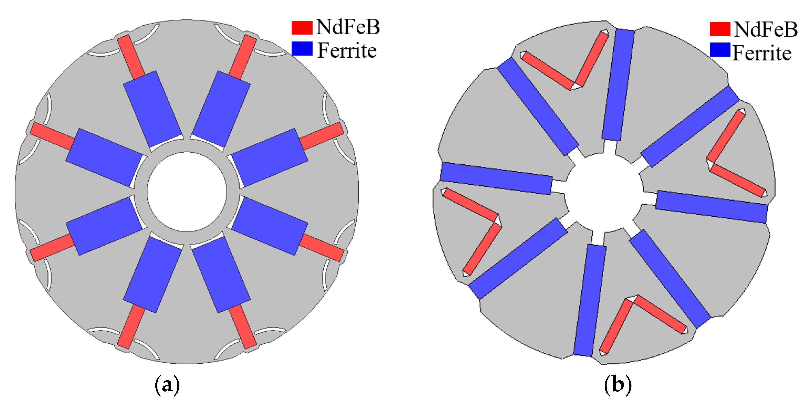
As previously mentioned, in the PMC-HTPMM, both ferrite and NdFeB are radially positioned, using rectangular shapes to represent both the materials, with their axes aligned. The spoke-type rotor topology incorporates appropriately designed separating holes to reduce the leakage flux, Which can be significant. To acquire ideal motor output data, the preliminary determination of the dimensions of the ferrite and NdFeB is necessary. Subsequently, finite element analysis software is employed for the parameterized modeling of the motor. Genetic algorithms are then applied for multi-objective optimization design of multiple parameters, resulting in the required dimensions. The spoke-type rotor generates a considerable harmonic air-gap flux, significantly affecting the sinusoidal behavior of the back electromotive force (EMF). In this design, unique arc-shaped separating holes have been used, markedly improving the air gap flux waveform, and substantially reducing the torque ripple in the motor.
Figure 6 illustrates the parameters involved in multi-objective optimization. Specifically,
w1 and
w2 represent the widths of ferrite and NdFeB, respectively, while
h1 and
h2 represent their respective lengths. Additionally, the parameters introduced are the inner
rin and outer circular rad
rout of the inter-magnet hole. Throughout optimization, the combined lengths of ferrite and NdFeB, represented by
h1 and
h2, respectively, were constrained to 18.4. The area of NdFeB was consistently set at 14 mm
2. To explore the influence of variations in
w1 and
w2 on the motor’s output performance, an investigation was conducted.
Figure 7 presents the changes in the motor’s average output torque as
w1 and
w2 vary under an effective current input of 5 A. Remarkably, it is evident that the average torque shows an ascending trend with the increase in
w2. However, as
w1 gradually increases, the output torque initially rises, followed by a subsequent decrement.
Commencing the optimization process for the PMC-HTPMM, we initially define the objective function, aiming to maximize the motor’s output torque in relation to its initial torque while concurrently ensuring that the torque ripple remains below 20%. The constraints are then meticulously outlined to guarantee the optimized motor aligns with practical application requirements, notably maintaining the sum of the ferrite and NdFeB lengths at 18.4. Referring to the initial parameters outlined in
Table 2 and the optimization range specified in
Table 3 for the SMC-HTPMM, the crucial input parameters, including
w1,
w2,
rout,
h1,
h2, and
rin, are systematically selected.
Iterative optimization is performed using JMAG, dynamically adjusting the input parameters to optimize the predefined objective function. Each iteration adapts the motor’s design parameters based on continuous feedback from both the objective function and the established constraint conditions. This structured approach ensures a systematic exploration of the optimization landscape, ultimately refining the PMC-HTPMM design for enhanced performance.
Figure 8 depicts the variation in the motor’s torque ripple concerning the changes in
w1 and
w2. It is evident from the graph that
w2 has a minimal impact on the motor’s torque ripple. However, the magnitude of
w1 significantly influences the torque ripple, showing a decreasing trend as
w1 increases. This suggests that the dimensions of NdFeB notably affect the motor output performance.
Figure 9 illustrates the optimization results, revealing that a substantial portion in the bottom-right corner meets the motor design requirements. It is essential to strike a balance between the average torque value and torque ripple rate when selecting the optimal parameters. The final parameters, as depicted in
Table 4, serve as a refined configuration that satisfies both the design criteria, enhancing the overall performance of the motor.
3.3. SMC-HTPMM
The newly proposed series hybrid permanent magnet motor’s topology is based on the spoke-type rotor composed of ferrite. In addition to ferrite, a pair of NdFeB V-shaped permanent magnets are added at each N pole. This structure significantly enhances the air-gap magnetic field density. However, this asymmetric structure causes substantial air-gap magnetic flux density distortion. Therefore, optimizing the rotor topology is necessary. In this study, optimization involves not only the dimensions and placement positions of the two types of magnetic steel, but also the parameterized analysis of the angle between the adjacent, radially placed ferrites. The motor optimization parameters are shown in
Figure 10.
In
Figure 10, the multi-objective optimization parameters for the series magnetic circuit are presented. The respective widths of ferrite and NdFeB, represented by
w1 and
w2, and the respective lengths of ferrite and NdFeB, denoted as
h1 and
h2, are crucial aspects of this unique asymmetric structure. To optimize this configuration, the angles between the adjacent permanent magnets must be considered, with
α1 and
α2 signifying the angles between ferrite and NdFeB, respectively. The optimization process adheres to the initial parameters outlined in
Table 5 and follows the specified optimization range detailed in
Table 6 for the SMC-HTPMM. This ensures a comprehensive exploration within defined bounds to achieve an optimized series magnetic circuit configuration.
The harmonics in the no-load back EMF is a significant factor causing torque ripples in the motor. THD is introduced here to characterize the sinusoidal Ty of the no-load back EMF.
Figure 11 illustrates the variation in the THD and cogging torque peak-to-peak value of the motor at 1000 r/min with the angle α
1. It is observed that they both exhibit similar trends. In contrast to the conventional motors, in the SMC-HTPMM, when α
1 is 50°, both the THD and cogging torque reach their minimum values. The minimum THD is 5.5%, and the minimum cogging torque peak-to-peak value is 0.15 N.m. This verifies the substantial impact of THD of the no-load back EMF on the cogging torque; a smaller THD corresponds to a smaller cogging torque in the motor.
Figure 12 presents the final optimization results.
For the ease of comparison, both the PMC-HTPMM and SMC-HTPMM utilized the same quantity of NdFeB.
Figure 12 presents the optimization results for the SMC-HTPMM, with the bottom-right corner displaying the available choices. Similar to the optimization process for the PMC-HTPMM, a comprehensive consideration of both the motor’s average torque value and torque ripple rate is crucial. The final motor parameters are detailed in
Table 7, reflecting a judicious selection that balances these key performance criteria.
3.4. Cost Analysis
Due to the sharp rise in the prices of rare earth materials, and thus permanent magnet materials, currently, NdFeB is the most commonly used material in permanent magnet motors. However, its high cost has been a limiting factor for the industrial development of permanent magnet motors. Presently, the cost of NdFeB is USD 83.0 per kilogram, which is several times higher than that of ferrite. The price of ferrite materials remains at USD 5 per kilogram. As NdFeB has a density of 7500 kg/m3 and ferrite has a density of 5000 kg/m3, the cost of the permanent magnet materials for each type of motor is calculated as the product of volume, density, and unit price.
Table 8 below presents a cost comparison between the newly proposed HTPMM and the prototype. It can be observed that substituting some NdFeB with ferrite can significantly reduce the raw material costs. Ensuring an equivalent NdFeB volume, the cost of permanent magnet materials for the PMC-HTPMM and SMC-HTPMM is 67% and 71% of that of the prototype, respectively, while maintaining a comparable output performance. This aspect proves advantageous for industrial production.
5. Conclusions
In essence, our study aims to reduce the motor manufacturing costs by introducing two different rotor models for hybrid permanent magnet motors—series and parallel magnetic circuits. Using equal volumes of rare earth permanent magnet materials, we unveil various. performance differences compared to the prototype.
The HTPMM with a parallel magnetic circuit demonstrates a comparable output performance to the prototype in terms of the no-load back EMF, harmonic content, and average torque. Conversely, the hybrid permanent magnet motor with a series magnetic circuit, despite a slight increase in the fundamental amplitude of no-load back electromotive force and air-gap magnetic flux density, exhibits a superior excitation torque, resulting in the highest output torque among the three motors. Additionally, the newly proposed HTPMM presents a significant cost advantage in terms of the permanent magnet material costs, with PMC-HTPMMs material cost being 67% and SMC-HTPMMs being 71% of that of the prototype. However, the complex rotor topology may introduce additional production steps, necessitating the comprehensive consideration of this factor.
Of note, the study emphasizes the impact of THD of the no-load back electromotive force on motor excitation torque, establishing a trend between the THD and peak-to-peak values of no-load torque. The analysis of demagnetization resistance indicates that, in the parallel magnetic circuit motors, the extensive irreversible demagnetization of NdFeB occurs, while in the series magnetic circuit motors, less irreversible demagnetization occurs. Therefore, compared to the parallel magnetic circuit structure, the series magnetic circuit structure exhibits a lower demagnetization risk.
Looking ahead, detailed experimental results, particularly those related to prototype manufacturing, motor efficiency, and vibration noise, will be presented in future articles to provide a comprehensive understanding of the impact of these hybrid permanent magnet motors on motor manufacturing efficiency and performance optimization.


