
Control Strategies and Stabilization Techniques for DC/DC Converters Application in DC MGs: Challenges, Opportunities, and Prospects—A Review

 ,
,  , and
, and
Abstract
1. Introduction
1.1. Investigated Topologies for DC/DC Converters and Most Usable Types
1.2. Typical Ratings of DC Microgrids
2. Control Strategies for DC/DC Converters in DC MGs Applications
2.1. Model Predictive Control (MPC)
2.2. Backstepping Control (BSC)
2.3. Sliding Mode Controller (SMC)
2.4. Passivity-Based Control (PBC)
2.5. Artificial Intelligence-Based Control (AI)
2.6. Synergetic Control (SC)
2.7. Linear, Nonlinear and Piecewise Linear Droop Controllers
3. Stability Analysis of DC/DC Converters in DC MGs Applications
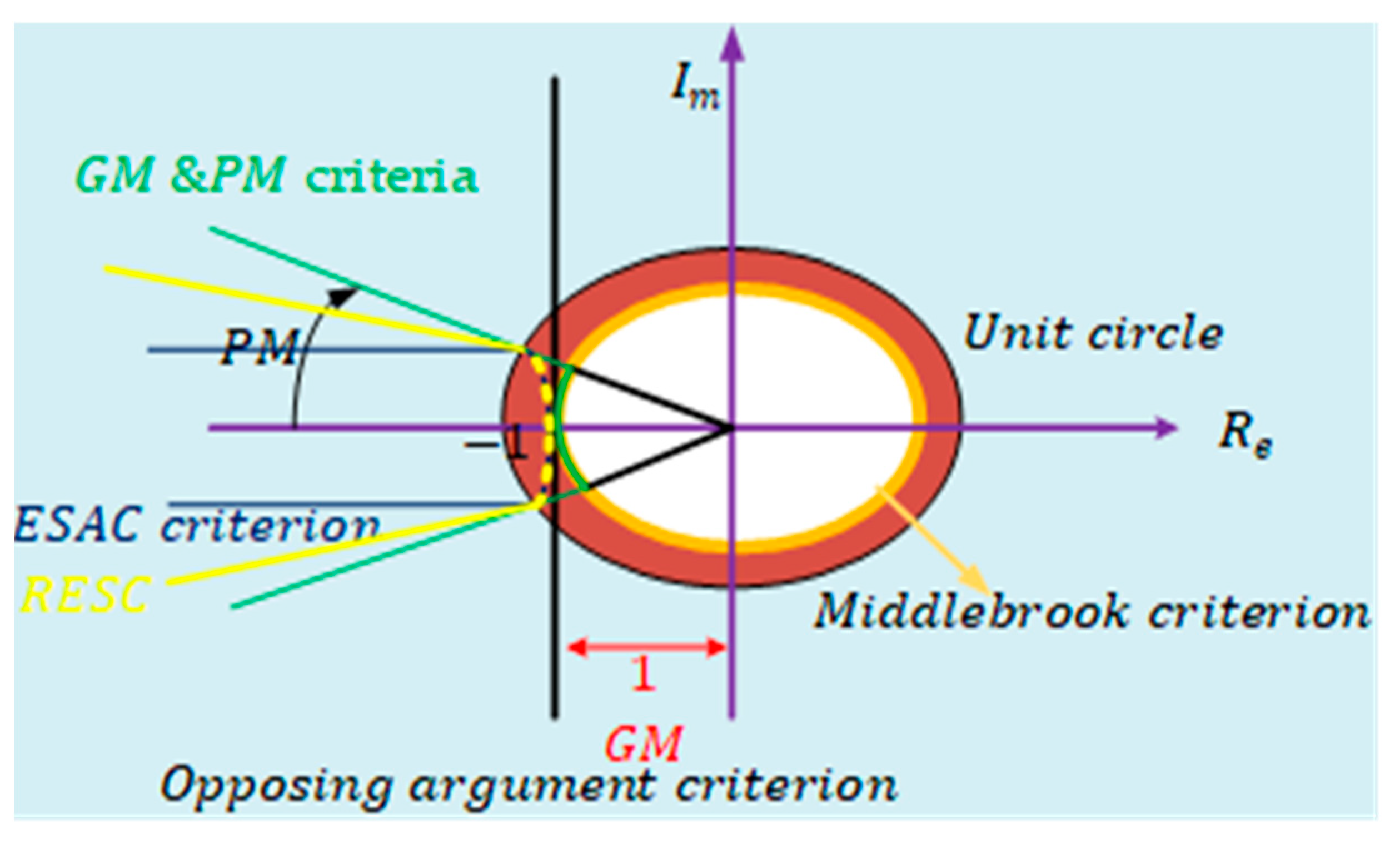
3.1. The Middlebrook Criterion
3.2. Gain Margin and Phase Margin Criterion (GMPM)
3.3. The Opposing Argument Criterion
3.4. Energy Source Analysis Consortium (ESAC) Criterion
3.5. Three-Step Impedance Criterion (TSIC)
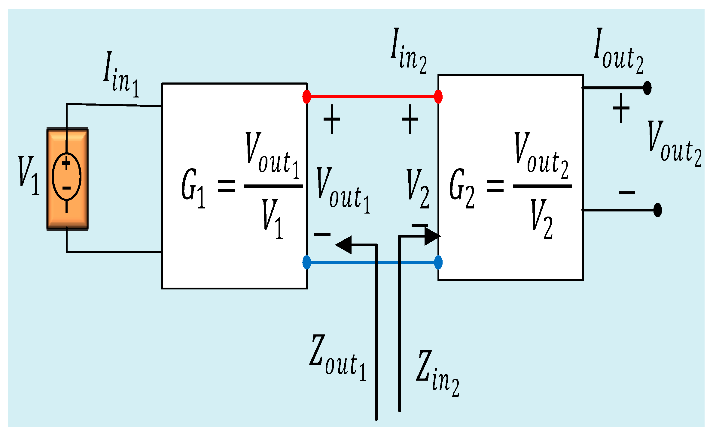
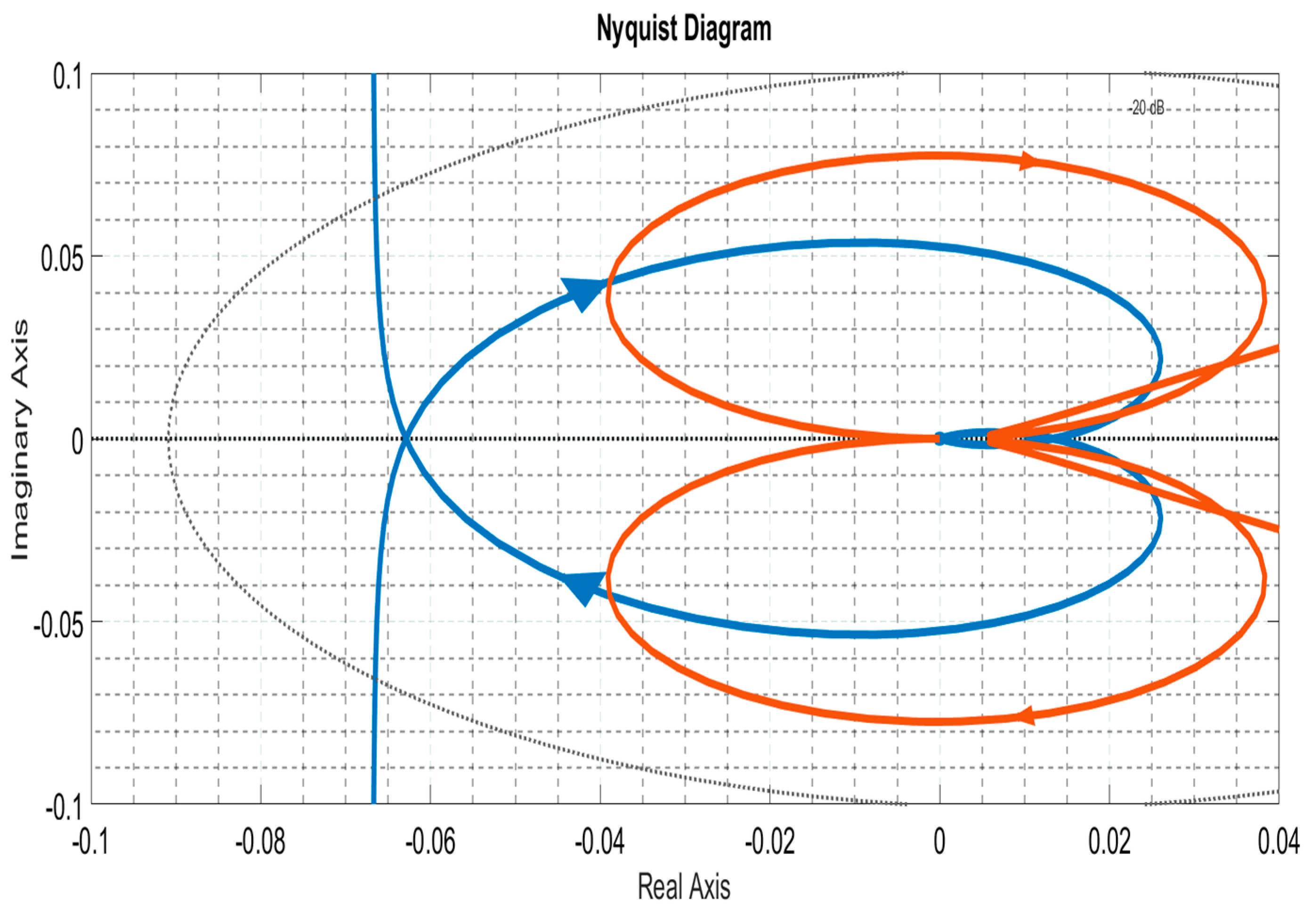
- System stability analysis: After determining the transfer function between the output voltage and the input voltage, and the provided in Equation (17), the stability of the system is analyzed as follows:where and represent the extended minor-loop gain, the input impedances of the downstream n subsystems, and the output impedance of the upstream subsystem connected to downstream n subsystems, respectively [101]. (The input subsystems are interconnected with output subsystems through a single bus bar arrangement and PWM for switching operations.) The Nyquist plot is employed to determine the stability condition. Specifically, if the extended minor-loop gain Nyquist plot does not encircle the point (−1, 0), the system is stable [63,74,96].
3.6. μ-Sensitivity Criterion
- (a)
- Obtain a symbolically linearized model of the system at the equilibrium point. If the system matrix contains nonlinearities, replace them with their approximate polynomial form before creating an LFT-based model.
- (b)
3.7. Phase-Plane Analysis
3.8. Bifurcation Analysis
3.9. Kalman–Yakubovich–Popov Lemma Stability Criterion
3.10. Lyapunov Stability Criterion
4. Stabilization Techniques for DC/DC Converters in DC MGs

| Major Techniques | Advantages | Disadvantages | Application | Determination Method | Limitations |
|---|---|---|---|---|---|
| Applying virtual impedance method for CPLs [83,84,89,118] | Enhances system damping, provides robustness, eliminates DC bus voltage oscillation, improves power quality, mitigates instability in GFM and DC MGs. Unaffected by physical conditions, increases system stability, and enhances power-sharing efficiency. | Closed-loop bandwidth limitation. Voltage regulation cannot be relied upon. | Appropriate for smart inverters in weak grids, useful for DC and AC microgrids (MGs) with modified control loops. Introduces impedance-forming modules (IFMs) for high-bandwidth virtual impedance in grid-connected converters. Suitable for GFM inverters during unbalanced grid faults, intervening in frequency and voltage regulation. Pertinent for cascaded DC/DC converters. | Nyquist stability criterion Lyapunov stability criterion Hurwitz stability criterion | Voltage drops in individual micro-sources are unmentioned due to voltage loop modification. The nature of each DER is not considered. The characteristics of transmission lines are not addressed, impacting controller and power-sharing strategy selection. Black-box impedance prediction is infeasible under varying conditions. |
| Robust stability framework [119,120] | Applicable for solving convex optimization problems, as its complexity does not increase with the number of buses in MGs. Demonstrates effectiveness and non-conservativeness, verifiable through software. | Infeasible for nonlinear systems with polytypic uncertainties in their system matrices. Inapplicable to systems with known equilibrium conditions based on the nominal value of CPLs. | It is befitting DC MGs with uncertain CPLs power and often changes over time. It is suitable for linear systems. | Hurwitz stability criterion Lyapunov function and usually small gain based | Method efficiency established using the Hurwitz stability criterion and Lyapunov function, exhibiting different properties from other stability criteria. Introduces complexity to the system and ignores the impact of disturbances. |
| Brayton -Moser’s mixed potential theory [121] | Examines DC MGs stability through large signal stability. Compatible with microgrids having master and slave micro sources, eliminating the need for communication means. | It does not apply to linear systems with small signal stability. | Feasible for real applications in DC MGs and multiple converters loaded with CPLs. Applicable to electric motor drives with power electronic converters [122]. Recommended for DC distribution power systems, encompassing wind, solar PV, fuel cell, and grid-connected converters. | Proportional Integral Derivative (PID) controller | The nature of DERs is not exploited. Brayton–Moser’s mixed potential theory is suitable for large-signal stability analysis during significant disturbances but not for small-signal stability analysis in DC/DC converters supplying power systems [66,123]. |
| Passive damping technique [93,96] | The system can be easily modified by incorporating resistors, capacitors, or inductors in parallel, series, or cascade configurations, with either the inductor or capacitor in the input filter. | Increases losses, weight, and size of the system, raising the price, attributed to lower power efficiency compared to passive damping methods. | Poorly damped system. In a DC aircraft power system operating in the discontinuous conduction mode (DCM), it is advantageous to have a parallel source driving CPLs in both the continuous conduction mode (CCM) and the discontinuous conduction mode. | Middlebrook’s criterion Nyquist stability criterion | Cost estimation and power losses are overlooked, achievable by adding resistors in series or parallel to the filters. The nature of DC MGs is disregarded, ignoring the diverse capabilities and characteristics of most DERs. |
| Active damping techniques [93,96] | Increases input impedance. Modifies output impedance and control loops by adding shunt impedance. Outperforms passive damping techniques in terms of power efficiency. Applicable to linear systems. | Increases system price. Injects stabilizing power into the CPL, potentially affecting load performance negatively. Requires an additional circuit, raising costs and causing power losses. | Incorporating linear feedback control, modifying the system’s loop gain and generating damping effects akin to real damping elements without sacrificing efficiency, is applicable for small-signal stabilization techniques. Suitable for Voltage Source Converters (VSCs) in DC microgrids (MGs). Cascading converters are recommended when the CPL feeder is an uncontrollable LC filter. | Middlebrook’s criterion and Middlebrook’s extra theorem (EET). Nyquist stability criterion. Root locus stability criterion | Cost estimation and power losses are overlooked. Characteristics of transmission lines and the nature of DERs are not considered. The added feedback loops may not function satisfactorily beyond their immediate vicinity, and linear feedback stabilization techniques are only valid for analyzed operating points, posing a disadvantage. The method is determined under Middlebrook and Nyquist stability criteria. |
4.1. Virtual Impedance Construction for CPLs
4.2. Brayton–Moser’s Mixed Potential Theory
4.3. Passive Damping Technique
4.4. Active Damping Technique
5. Discussion
6. Conclusions and Future Research Prospects
Funding
Acknowledgments
Conflicts of Interest
References
- He, J.; Chen, Y.; Lin, J.; Chen, J.; Cheng, L.; Wang, Y. Review of Modeling, Modulation, and Control Strategies for the Dual-Active-Bridge DC/DC Converter. Energies 2023, 16, 6646. [Google Scholar] [CrossRef]
- Market.Us. Power Electronic Market Size to Surpass USD 94.21 Bn Revenue by 2032. Available online: https://www.globenewswire.com/en/news-release/2023/04/13/2646669/0/en/Power-Electronic-Market-Size-to-Surpass-USD-94-21-Bn-Revenue-by-2032.html (accessed on 30 September 2023).
- Lucas Nülle—Controlling Energy from Microgrids. Available online: https://www.lucas-nuelle.us/2808n1094 (accessed on 14 January 2024).
- Forouzesh, M.; Siwakoti, Y.P.; Gorji, S.A.; Blaabjerg, F.; Lehman, B. Step-Up DC-DC converters: A comprehensive review of voltage-boosting techniques, topologies, and applications. IEEE Trans. Power Electron. 2017, 32, 9143–9178. [Google Scholar] [CrossRef]
- Strzelecki, R.; Benysek, G. Power Electronics in Smart Electrical Energy Networks; Springer: Berlin/Heidelberg, Germany, 2008; Volume 34. [Google Scholar] [CrossRef]
- Guney, M.S.; Tepe, Y. Classification and assessment of energy storage systems. Renew. Sustain. Energy Rev. 2017, 75, 1187–1197. [Google Scholar] [CrossRef]
- Arrua, S. DC Bus Stabilization and Dynamic Performance Improvement of a Multi-Converter System. Ph.D. Thesis, University of South Carolina, Columbia, SC, USA, 2019. [Google Scholar]
- Elsayed, A.T.; Youssef, T.A.; Mohammed, O.A. Modeling and Control of a Low-Speed Flywheel Driving System for Pulsed-Load Mitigation in DC Distribution Networks. IEEE Trans. Ind. Appl. 2016, 52, 3378–3387. [Google Scholar] [CrossRef]
- Neely, J.; Pekarek, S.; DeCarlo, R.; Vaks, N. Real-time hybrid model predictive control of a boost converter with constant power load. In Proceedings of the 2010 Twenty-Fifth Annual IEEE Applied Power Electronics Conference and Exposition (APEC), Palm Springs, CA, USA, 21–25 February 2010; pp. 480–490. [Google Scholar] [CrossRef]
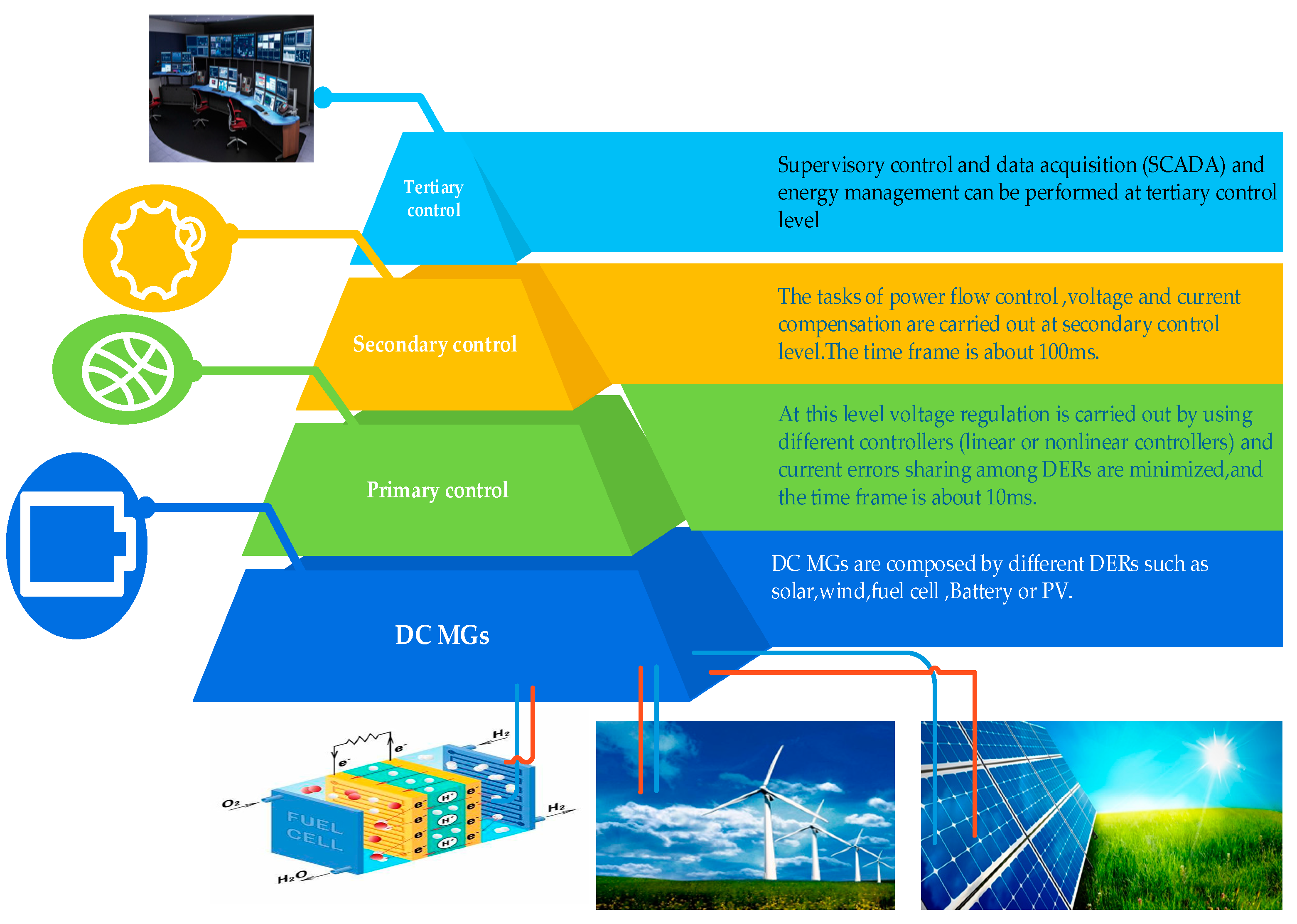
- Feng, X.; Shekhar, A.; Yang, F.; Hebner, R.E.; Bauer, P. Comparison of Hierarchical Control and Distributed Control for Microgrid. Electr. Power Compon. Syst. 2017, 45, 1043–1056. [Google Scholar] [CrossRef]
- Jackson, R.; Zulkifli, S.A.; Benbouzid, M.; Salimin, S.; Khan, M.H.; Elhassan, G.; Pathan, E. A comprehensive motivation of multilayer control levels for microgrids: Synchronization, voltage and frequency restoration perspective. Appl. Sci. 2020, 10, 8355. [Google Scholar] [CrossRef]
- Al-Tameemi, Z.H.A.; Lie, T.T.; Foo, G.; Blaabjerg, F. Control strategies of DC microgrids cluster: A comprehensive review. Energies 2021, 14, 7569. [Google Scholar] [CrossRef]
- Meng, L.; Luna, A.; Díaz, E.R.; Sun, B.; Dragicevic, T.; Savaghebi, M.; Vasquez, J.C.; Guerrero, J.M.; Graells, M.; Andrade, F. Flexible System Integration and Advanced Hierarchical Control Architectures in the Microgrid Research Laboratory of Aalborg University. IEEE Trans. Ind. Appl. 2016, 52, 1736–1749. [Google Scholar] [CrossRef]
- Guerrero, J.M.; Vasquez, J.C.; Matas, J.; De Vicuña, L.G.; Castilla, M. Hierarchical control of droop-controlled AC and DC microgrids—A general approach toward standardization. IEEE Trans. Ind. Electron. 2011, 58, 158–172. [Google Scholar] [CrossRef]
- Litrán, S.P.; Durán, E.; Semião, J.; Díaz-Martín, C. Multiple-Output DC-DC Converters: Applications and Solutions. Electronics 2022, 11, 1258. [Google Scholar] [CrossRef]
- Igliński, B.; Skrzatek, M.; Kujawski, W.; Cichosz, M.; Buczkowski, R. SWOT Analysis of Renewable Energy Sector in Mazowieckie Voivodeship (Poland): Current Progress, Prospects and Policy Implications; Springer: Dordrecht, The Netherlands, 2022; Volume 24, No. 1. [Google Scholar] [CrossRef]
- Dhananjaya, M.; Pattnaik, S. Design and implementation of a SIMO DC–DC converter. IET Power Electron. 2019, 12, 1868–1879. [Google Scholar] [CrossRef]
- Nahata, P.; La Bella, A.; Scattolini, R.; Ferrari-Trecate, G. Hierarchical Control in Islanded DC Microgrids with Flexible Structures. IEEE Trans. Control Syst. Technol. 2021, 29, 2379–2392. [Google Scholar] [CrossRef]
- Behjati, H.; Davoudi, A. A multiple-input multiple-output DC-DC converter. IEEE Trans. Ind. Appl. 2013, 49, 1464–1479. [Google Scholar] [CrossRef]
- Onar, O.C.; Khaligh, A. A novel integrated magnetic structure based DC/DC converter for hybrid battery/ultracapacitor energy storage systems. IEEE Trans. Smart Grid 2012, 3, 296–307. [Google Scholar] [CrossRef]
- Braitor, A. Advanced Hierarchical Control and Stability Analysis of DC Microgrids; Springer: Berlin/Heidelberg, Germany, 2020. [Google Scholar]
- Aranda, E.D.; Litran, S.P.; Prieto, M.B.F. Combination of interleaved single-input multiple-output DC-DC converters. CSEE J. Power Energy Syst. 2022, 8, 132–142. [Google Scholar] [CrossRef]
- Ali, S.; Zheng, Z.; Aillerie, M.; Sawicki, J.P.; Péra, M.C.; Hissel, D. A review of dc microgrid energy management systems dedicated to residential applications. Energies 2021, 14, 4308. [Google Scholar] [CrossRef]
- Moussa, S.; Ghorbal, M.J.B.; Slama-Belkhodja, I. Bus voltage level choice for standalone residential DC nanogrid. Sustain. Cities Soc. 2019, 46, 101431. [Google Scholar] [CrossRef]
- Dragičević, T.; Lu, X.; Vasquez, J.C.; Guerrero, J.M. DC Microgrids—Part II: A Review of Power Architectures, Applications, and Standardization Issues. IEEE Trans. Power Electron. 2016, 31, 3528–3549. [Google Scholar] [CrossRef]
- Xu, Q.; Yan, Y.; Zhang, C.; Dragicevic, T.; Blaabjerg, F. An Offset-Free Composite Model Predictive Control Strategy for DC/DC Buck Converter Feeding Constant Power Loads. IEEE Trans. Power Electron. 2020, 35, 5331–5342. [Google Scholar] [CrossRef]
- Xu, Q.; Vafamand, N.; Chen, L.; Dragicevic, T.; Xie, L.; Blaabjerg, F. Review on Advanced Control Technologies for Bidirectional DC/DC Converters in DC Microgrids. IEEE J. Emerg. Sel. Top. Power Electron. 2021, 9, 1205–1221. [Google Scholar] [CrossRef]
- Bento, F.; Cardoso, A.J.M. Model-Free Predictive Control of Multilevel DC-DC Converters for Energy Storage Applications. In Proceedings of the IECON 2022—48th Annual Conference of the IEEE Industrial Electronics Society, Brussels, Belgium, 17–20 October 2022; pp. 1–5. [Google Scholar] [CrossRef]
- Kumar, D.; Kumar, C. Model Predictive Control of Bi-directional dc-dc Converter for Battery Charger Application. In Proceedings of the 2022 22nd National Power Systems Conference (NPSC), New Delhi, India, 17–19 December 2022; pp. 65–70. [Google Scholar] [CrossRef]
- Zhou, J.; Hassan, M.A.; Zhang, J.; Hou, M.; Wu, S.; Xing, G.; Chi, S. Stabilization of constant power loads in dc microgrid systems using an adaptive continuous control set model predictive control. Symmetry 2021, 13, 1112. [Google Scholar] [CrossRef]
- Wang, L. Model Predictive Control: Design and implementation using MATLAB (T-3). In Proceedings of the 2009 American Control Conference, St. Louis, MO, USA, 10–12 June 2009. [Google Scholar] [CrossRef]
- Truong, Q. Continuous-Time Model Predictive Control. Master’s Thesis, RMIT University, Melbourne, Australia, 2007; pp. 1–162. [Google Scholar]
- Pannocchia, G. Handbook of Model Predictive Control [Bookshelf]. IEEE Control Syst. Mag. 2022, 40, 96–99. [Google Scholar] [CrossRef]
- Raković, S.V. Model Predictive Control: Classical, Robust, and Stochastic [Bookshelf]. IEEE Control Syst. Mag. 2016, 36, 102–105. [Google Scholar] [CrossRef]
- Khan, M.S.; Ahmad, I.; Armaghan, H.; Ali, N. Backstepping sliding mode control of FC-UC based hybrid electric vehicle. IEEE Access 2018, 6, 77202–77211. [Google Scholar] [CrossRef]
- Beccuti, A.G.; Mariéthoz, S.; Cliquennois, S.; Wang, S.; Morari, M. Explicit model predictive control of DC-DC switched-mode power supplies with extended kalman filtering. IEEE Trans. Ind. Electron. 2009, 56, 1864–1874. [Google Scholar] [CrossRef]
- Kumar, J.; Agarwal, A.; Agarwal, V. A review on overall control of DC microgrids. J. Energy Storage 2019, 21, 113–138. [Google Scholar] [CrossRef]
- Wu, J.; Lu, Y. Adaptive Backstepping Sliding Mode Control for Boost Converter With Constant Power Load. IEEE Access 2019, 7, 50797–50807. [Google Scholar] [CrossRef]
- Zhang, M.; Li, Y.; Liu, F.; Luo, L.; Cao, Y.; Shahidehpour, M. Voltage stability analysis and sliding-mode control method for rectifier in DC systems with constant power loads. IEEE J. Emerg. Sel. Top. Power Electron. 2017, 5, 1621–1630. [Google Scholar] [CrossRef]
- Martinez-Treviño, B.A.; El Aroudi, A.; Vidal-Idiarte, E.; Cid-Pastor, A.; Martinez-Salamero, L. Sliding-mode control of a boost converter under constant power loading conditions. IET Power Electron. 2019, 12, 521–529. [Google Scholar] [CrossRef]
- Singh, S.; Kumar, V.; Fulwani, D. Mitigation of destabilising effect of CPLs in island DC micro-grid using non-linear control. IET Power Electron. 2017, 10, 387–397. [Google Scholar] [CrossRef]
- Amrr, S.M.; Ahmad, J.; Waheed, S.A.; Sarwar, A.; Saidi, A.S.; Nabi, M. Finite-Time Adaptive Sliding Mode Control of a Power Converter Under Multiple Uncertainties. Front. Energy Res. 2022, 10, 901606. [Google Scholar] [CrossRef]
- Su, L.; Gupta, V.; Antsaklis, P. Feedback Passivation of Linear Systems with Fixed-Structure Controllers. IEEE Control Syst. Lett. 2020, 4, 498–503. [Google Scholar] [CrossRef]
- Fujimoto, K.; Sakata, N.; Maruta, I.; Ferguson, J. A Passivity Based Sliding Mode Controller for Simple Port-Hamiltonian Systems. IEEE Control Syst. Lett. 2021, 5, 839–844. [Google Scholar] [CrossRef]
- Kwasinski, A.; Krein, P.T. Passivity-based control of buck converters with constant-power loads. In Proceedings of the 2007 IEEE Power Electronics Specialists Conference, Orlando, FL, USA, 17–21 June 2007; pp. 259–265. [Google Scholar] [CrossRef]
- Mehta, A.; Naik, B. Sliding Mode Controllers for Power Electronic Converters; Springer: Berlin/Heidelberg, Germany, 2019; Volume 534. [Google Scholar] [CrossRef]
- Alam, F.; Haider Zaidi, S.S.; Rehmat, A.; Mutarraf, M.U.; Nasir, M.; Guerrero, J.M. Robust Hierarchical Control Design for the Power Sharing in Hybrid Shipboard Microgrids. Inventions 2022, 8, 7. [Google Scholar] [CrossRef]
- Tan, S.C.; Lai, Y.M.; Tse, C.K. Implementation of pulse-width-modulation based sliding mode controller for boost converters. IEEE Power Electron. Lett. 2005, 3, 130–135. [Google Scholar] [CrossRef]
- Zeng, J.; Zhang, Z.; Qiao, W. An interconnection and damping assignment passivity-based controller for a DC-DC boost converter with a constant power load. IEEE Trans. Ind. Appl. 2014, 50, 2314–2322. [Google Scholar] [CrossRef]
- Kondratiev, I.; Dougal, R. Synergetic control strategies for shipboard DC power distribution systems. In Proceedings of the 2007 American Control Conference, New York, NY, USA, 9–13 July 2007; pp. 4744–4749. [Google Scholar] [CrossRef]
- Kondratiev, I.; Dougal, R.; Santi, E.; Veselov, G. Synergetic control for DC-DC buck converters with constant power load. In Proceedings of the 2004 IEEE 35th Annual Power Electronics Specialists Conference, Aachen, Germany, 20–25 June 2004; Volume 5, pp. 3758–3764. [Google Scholar] [CrossRef]
- Khan, H.S.; Mohamed, I.S.; Kauhaniemi, K.; Liu, L. Artificial Neural Network-Based Voltage Control of DC/DC Converter for DC Microgrid Applications. In Proceedings of the 2021 6th IEEE Workshop on the Electronic Grid (eGRID), New Orleans, LA, USA, 8–10 November 2021; pp. 1–6. [Google Scholar] [CrossRef]
- Koduru, S.S.; MacHina, V.S.P.; Madichetty, S. Real-Time Implementation of Deep Learning Technique in Microcontroller-Based DC-DC Boost Converter—A Design Approach. In Proceedings of the 2022 IEEE Delhi Section Conference (DELCON), New Delhi, India, 11–13 February 2022; pp. 1–6. [Google Scholar] [CrossRef]
- Wang, Y.; Nguyen, T.L.; Syed, M.H.; Xu, Y.; Guillo-Sansano, E.; Nguyen, V.-H.; Burt, G.M.; Tran, Q.-T.; Caire, R. A Distributed Control Scheme of Microgrids in Energy Internet Paradigm and Its Multisite Implementation. IEEE Trans. Ind. Inform. 2021, 17, 1141–1153. [Google Scholar] [CrossRef]
- Farsizadeh, H.; Gheisarnejad, M.; Mosayebi, M.; Rafiei, M.; Khooban, M.H. An Intelligent and Fast Controller for DC/DC Converter Feeding CPL in a DC Microgrid. IEEE Trans. Circuits Syst. II Express Briefs 2020, 67, 1104–1108. [Google Scholar] [CrossRef]
- Hussaini, H.; Member, S.; Yang, T.; Member, S.; Bai, G.; Member, S. Artificial Intelligence-Based Hierarchical Control Design for Current Sharing and Voltage Restoration in DC Microgrid of the More Electric Aircraft. IEEE Trans. Transp. Electrif. 2023; early access. [Google Scholar] [CrossRef]
- Sorouri, H.; Sedighizadeh, M.; Oshnoei, A.; Khezri, R. International Journal of Electrical Power and Energy Systems An intelligent adaptive control of DC—DC power buck converters. Int. J. Electr. Power Energy Syst. 2022, 141, 108099. [Google Scholar] [CrossRef]
- Hassan, M.A.; Su, C.-L.; Pou, J.; Sulligoi, G.; Almakhles, D.; Bosich, D.; Guerrero, J.M. DC Shipboard Microgrids with Constant Power Loads: A Review of Advanced Nonlinear Control Strategies and Stabilization Techniques. IEEE Trans. Smart Grid 2022, 13, 3422–3438. [Google Scholar] [CrossRef]
- Zhang, Y.; Qu, X.; Tang, M.; Yao, R.; Chen, W. Design of Nonlinear Droop Control in DC Microgrid for Desired Voltage Regulation and Current Sharing Accuracy. IEEE J. Emerg. Sel. Top. Circuits Syst. 2021, 11, 168–175. [Google Scholar] [CrossRef]
- Lin, Y.; Member, S.; Xiao, W.; Member, S. Novel Piecewise Linear Formation of Droop Strategy for DC Microgrid. IEEE Trans. Smart Grid 2019, 10, 6747–6755. [Google Scholar] [CrossRef]
- Chen, F.; Burgos, R.; Boroyevich, D.; Vasquez, J.C.; Guerrero, J.M. Investigation of Nonlinear Droop Control in DC Power Distribution Systems: Load Sharing, Voltage Regulation, Efficiency, and Stability. IEEE Trans. Power Electron. 2019, 34, 9404–9421. [Google Scholar] [CrossRef]
- Shah, S.U.; Charan, D.C.S.; Rajpathak, B. Application of Piecewise-smooth System Theory in Droop Control. In Proceedings of the 2021 9th IEEE International Conference on Power Systems (ICPS), Kharagpur, India, 16–18 December 2021. [Google Scholar] [CrossRef]
- Riccobono, A.; Santi, E. Comprehensive review of stability criteria for DC power distribution systems. IEEE Trans. Ind. Appl. 2014, 50, 3525–3535. [Google Scholar] [CrossRef]
- Xu, Q.; Zhang, C.; Wen, C.; Wang, P. A Novel Composite Nonlinear Controller for Stabilization of Constant Power Load in DC Microgrid. IEEE Trans. Smart Grid 2017, 10, 752–761. [Google Scholar] [CrossRef]
- Wang, J.; Luo, W.; Liu, J.; Wu, L. Adaptive Type-2 FNN-Based Dynamic Sliding Mode Control of DC-DC Boost Converters. IEEE Trans. Syst. Man Cybern. Syst. 2021, 51, 2246–2257. [Google Scholar] [CrossRef]
- Mestriner, D.; Rosini, A.; Xhani, I.; Bonfiglio, A.; Procopio, R. Primary Voltage and Frequency Regulation in Inverter Based Islanded Microgrids through a Model Predictive Control Approach. Energies 2022, 15, 5077. [Google Scholar] [CrossRef]
- Simiyu, P.; Xin, A.; Bitew, G.T.; Shahzad, M.; Kunyu, W.; Kamunyu, P.M. Small-signal stability analysis for the multi-terminal VSC MVDC distribution network; a review. J. Eng. 2019, 2019, 1068–1075. [Google Scholar] [CrossRef]
- Karppanen, M.; Suntio, T. Minor-loop gain as a source of information on robust stability and transient performance in an interconnected system. EPE J. 2009, 19, 28–35. [Google Scholar] [CrossRef]
- Ma, D.; Ki, W.H.; Tsui, C.Y. A pseudo-CCM/DCM SIMO switching converter with freewheel switching. IEEE J. Solid-State Circuits 2003, 38, 1007–1014. [Google Scholar] [CrossRef]
- Liao, Y.; Wang, X. Impedance-Based Stability Analysis for Interconnected Converter Systems with Open-Loop RHP Poles. IEEE Trans. Power Electron. 2020, 35, 4388–4397. [Google Scholar] [CrossRef]
- Kuhn, M.R.; Ji, Y.; Schrder, D. Stability studies of critical DC power system component for more electric aircraft using μ sensitivity. In Proceedings of the 2007 Mediterranean Conference on Control & Automation, Athens, Greece, 27–29 June 2007. [Google Scholar] [CrossRef]
- Alam, M.Z.; Roy, T.K.; Ghosh, S.K.; Mohammad, N.; Paul, L.C. Output Voltage Stability of a DC-DC Buck Converter via an Improved Backstepping Method. In Proceedings of the 2023 International Conference on Electrical, Computer and Communication Engineering (ECCE), Chittagong, Bangladesh, 23–25 February 2023; pp. 1–5. [Google Scholar] [CrossRef]
- Rivetta, C.; Williamson, G.A. Large-Signal Analysis of a DC-DC Buck Power Converter Operating with Constant Power Load. In Proceedings of the 29th Annual Conference of the IEEE Industrial Electronics Society (IECON’03), Roanoke, VA, USA, 2–6 November 2003; Volume 1, pp. 732–737. [Google Scholar] [CrossRef]
- Wang, X.; Yao, R.; Rao, F. Three-step impedance criterion for small-signal stability analysis in two-stage DC distributed power systems. IEEE Power Electron. Lett. 2003, 1, 83–87. [Google Scholar] [CrossRef]
- Grillo, S.; Musolino, V.; Sulligoi, G.; Tironi, E. Stability enhancement in DC distribution systems with constant power controlled converters. In Proceedings of the 2012 IEEE 15th International Conference on Harmonics and Quality of Power, Hong Kong, China, 17–20 June 2012; pp. 848–854. [Google Scholar] [CrossRef]
- Martirosyan, A.V.; Martirosyan, K.V.; Chernyshev, A.B. Investigation of Popov’s Lines’ Limiting Position to Ensure the Process Control Systems’ Absolute Stability. In Proceedings of the 2023 XXVI International Conference on Soft Computing and Measurements (SCM), Saint Petersburg, Russia, 24–26 May 2023; pp. 69–72. [Google Scholar] [CrossRef]
- Chettibi, N.; Mellit, A.; Sulligoi, G.; Pavan, A.M. Adaptive Neural Network-Based Control of a Hybrid AC/DC Microgrid. IEEE Trans. Smart Grid 2018, 9, 1667–1679. [Google Scholar] [CrossRef]
- Sabanovic, A.; Sabanovic, N.; Music, O. Sliding Mode Control of Dc-Ac Converters. In Proceedings of the 1986 17th Annual IEEE Power Electronics Specialists Conference, Vancouver, BC, Canada, 23–27 June 1986; pp. 560–566. [Google Scholar] [CrossRef]
- Zeng, X.; Li, Z.; Wu, Y.; Gao, W.; Zhang, J.; Ren, M.; Zhang, B. Dynamic Stability Analysis based on State-space Model and Lyapunov ’ s Stability Criterion for SiC-MOS and Si-IGBT Switching. In Proceedings of the 2018 IEEE 30th International Symposium on Power Semiconductor Devices and ICs (ISPSD), Chicago, IL, USA, 13–17 May 2018; pp. 268–271. [Google Scholar] [CrossRef]
- Wei, Y. Lyapunov Stability Theory for Nonlinear Nabla Fractional Order Systems. IEEE Trans. Circuits Syst. II Express Briefs 2021, 68, 3246–3250. [Google Scholar] [CrossRef]
- Long, F.; Pang, L.; Zhang, C.; He, Y. A novel augmented Lyapunov functional for the stability analysis of delayed neural networks. In Proceedings of the 2018 37th Chinese Control Conference (CCC), Wuhan, China, 25–27 July 2018; pp. 873–878. [Google Scholar]
- Ansari, S.; Zhang, J.; Singh, R.E. A review of stabilization methods for DCMG with CPL, the role of bandwidth limits and droop control. Prot. Control Mod. Power Syst. 2022, 7, 2. [Google Scholar] [CrossRef]
- Lu, X.; Sun, K.; Guerrero, J.M.; Vasquez, J.C.; Huang, L.; Wang, J. Stability Enhancement Based on Virtual Impedance for DC Microgrids with Constant Power Loads. IEEE Trans. Smart Grid 2015, 6, 2770–2783. [Google Scholar] [CrossRef]
- Liu, S.; Su, P.; Zhang, L. A virtual negative inductor stabilizing strategy for DC microgrid with constant power loads. IEEE Access 2018, 6, 59728–59741. [Google Scholar] [CrossRef]
- Zhao, Q.; Tao, F.; Hu, Y.; Lee, F.C. Active-clamp DC/DC converters using magnetic switches. In Proceedings of the APEC 2001. Sixteenth Annual IEEE Applied Power Electronics Conference and Exposition, Anaheim, CA, USA, 4–8 March 2001; Volume 2, pp. 946–952. [Google Scholar] [CrossRef]
- Rouzbehi, K.; Miranian, A.; Escaño, J.M.; Rakhshani, E.; Shariati, N.; Pouresmaeil, E. A Data-Driven Based Voltage Control Strategy for DC-DC Converters: Application to DC Microgrid. Electronics 2019, 8, 493. [Google Scholar] [CrossRef]
- Yousefizadeh, S.; Bendtsen, J.D.; Vafamand, N.; Khooban, M.H.; Dragicevic, T.; Blaabjerg, F. EKF-Based Predictive Stabilization of Shipboard DC Microgrids with Uncertain Time-Varying Load. IEEE J. Emerg. Sel. Top. Power Electron. 2019, 7, 901–909. [Google Scholar] [CrossRef]
- Ding, N.; Prasad, K.; Lie, T.T.; Cui, J. State of charge estimation of a composite lithium-based battery model based on an improved extended Kalman filter algorithm. Inventions 2019, 4, 66. [Google Scholar] [CrossRef]
- Laib, K.; Watson, J.; Ojo, Y.; Lestas, I. Decentralized Stability Conditions in DC Microgrids. In Proceedings of the 2021 60th IEEE Conference on Decision and Control (CDC), Austin, TX, USA, 14–17 December 2021; pp. 5659–5664. [Google Scholar] [CrossRef]
- Jeltsema, D.; Scherpen, J.M.A. On Brayton and Moser’s Missing Stability Theorem. IEEE Trans. Circuits Syst. II Express Briefs 2005, 52, 550–552. [Google Scholar] [CrossRef]
- Zekun, L.; Wei, P.; Li, K. Large-disturbance stability analysis of DC microgrid with constant power load and its transient voltage stability control strategy. In Proceedings of the 2018 China International Conference on Electricity Distribution (CICED), Tianjin, China, 17–19 September 2018; pp. 1686–1690. [Google Scholar] [CrossRef]
- Prabhakaran, P.; Goyal, Y.; Agarwal, V. Novel Nonlinear Droop Control Techniques to Overcome the Load Sharing and Voltage Regulation Issues in DC Microgrid. IEEE Trans. Power Electron. 2018, 33, 4477–4487. [Google Scholar] [CrossRef]
- Wu, M.; Lu, D.D.C. Active stabilization methods of electric power systems with constant power loads: A review. J. Mod. Power Syst. Clean Energy 2014, 2, 233–243. [Google Scholar] [CrossRef]
- Snehal, N.; Pooja, W.; Sonam, K. Model Predictive Control for DC-DC Buck Converter using Enumeration. In Proceedings of the 2020 52nd North American Power Symposium (NAPS), Tempe, AZ, USA, 11–13 April 2021; pp. 1–6. [Google Scholar] [CrossRef]
- Du, W.; Zhang, J.; Zhang, Y.; Qian, Z. Stability criterion for cascaded system with constant power load. IEEE Trans. Power Electron. 2013, 28, 1843–1851. [Google Scholar] [CrossRef]
- Singh, S.; Gautam, A.R.; Fulwani, D. Constant power loads and their effects in DC distributed power systems: A review. Renew. Sustain. Energy Rev. 2017, 72, 407–421. [Google Scholar] [CrossRef]
- Vesti, S.; Suntio, T.; Oliver, J.A.; Prieto, R.; Cobos, J.A. Impedance-based stability and transient-performance assessment applying maximum peak criteria. IEEE Trans. Power Electron. 2013, 28, 2099–2104. [Google Scholar] [CrossRef]
- Pires, V.F.; Romero-Cadaval, E.; Vinnikov, D.; Roasto, I.; Martins, J.F. Power converter interfaces for electrochemical energy storage systems—A review. Energy Convers. Manag. 2014, 86, 453–475. [Google Scholar] [CrossRef]
- Pan, F.; Chen, J.; Xiao, C.; Zhou, Z. Model predictive control of bidirectional DC/DC converters for hydrogen fuel cell vehicles. In Proceedings of the 2020 Chinese Automation Congress (CAC), Shanghai, China, 6–8 November 2020; pp. 5778–5782. [Google Scholar] [CrossRef]
- Katir, H.; Abouloifa, A.; Noussi, K.; Lachkar, I.; El Aroudi, A.; Aourir, M.; El Otmani, F.; Giri, F. Fault Tolerant Backstepping Control for Double-Stage Grid-Connected Photovoltaic Systems Using Cascaded H-Bridge Multilevel Inverters. IEEE Control Syst. Lett. 2022, 6, 1406–1411. [Google Scholar] [CrossRef]
- Hossain, E.; Perez, R.; Nasiri, A.; Padmanaban, S. A Comprehensive Review on Constant Power Loads Compensation Techniques. IEEE Access 2018, 6, 33285–33305. [Google Scholar] [CrossRef]
- Alharbi, K.S.; McCann, R.A. Non-Overparametrized Adaptive Backstepping Control of PWM DC-DC Non-Inverting Buck-Boost Power Converter. In Proceedings of the 2019 IEEE Green Technologies Conference (GreenTech), Lafayette, LA, USA, 3–6 April 2019; pp. 1–5. [Google Scholar] [CrossRef]
- Sudhoff, S.D.; Glover, S.F.; Lamm, P.; Schmucker, D.; Delisle, D. Admittance space stability analysis of power electronic systems. IEEE Trans. Aerosp. Electron. Syst. 2000, 36, 965–973. [Google Scholar] [CrossRef]
- Xu, J.-X. Sliding mode control in engineering. Automatica 2003, 39, 951–954. [Google Scholar] [CrossRef]
- Ahmadzadeh, S.; Markadeh, G.A.; Abiadi, N. Adaptive Sliding Mode Control of Step-Up/Step-Down Z-Source DC-DC Converter. In Proceedings of the 2019 27th Iranian Conference on Electrical Engineering (ICEE), Yazd, Iran, 30 April–2 May 2019; pp. 841–845. [Google Scholar]
- Liu, H.; Guo, W.; Cheng, D.; Wang, Y.; Wang, M. Stability and Bifurcation Analysis of DC Microgrid with Multiple Droop Control Sources and Loads. IEEE Trans. Power Electron. 2021, 36, 2361–2372. [Google Scholar] [CrossRef]
- Erokhina, E.; Kiselev, M.; Kryukov, K.; Tserkovsky, Y.; Lepanov, M. Analysis of processes in the boost DC-DC converter with sliding mode control. In Proceedings of the 2021 3rd International Youth Conference on Radio Electronics, Electrical and Power Engineering (REEPE), Moscow, Russia, 11–13 March 2021; pp. 3–8. [Google Scholar] [CrossRef]
- Murakawa, Y.; Hikihara, T. Regulation of Parallel Connected Boost and Buck Converters by Passivity-Based Control. In Proceedings of the 2020 IEEE Workshop on Wide Bandgap Power Devices and Applications in Asia (WiPDA Asia), Suita, Japan, 23–25 September 2020; pp. 14–18. [Google Scholar] [CrossRef]
- Riccobono, A.; Santi, E. A novel Passivity-Based Stability Criterion (PBSC) for switching converter DC distribution systems. In Proceedings of the 2012 Twenty-Seventh Annual IEEE Applied Power Electronics Conference and Exposition (APEC), Orlando, FL, USA, 5–9 February 2012; pp. 2560–2567. [Google Scholar] [CrossRef]
- Eguchi, K.; Shibata, A.; Asadi, F.; Ishibashi, T.; Harada, Y.; Oota, I. Design of an LED Sink Driver Using a Switched-Inductor and Switched-Capacitor Buck-Boost Converter with High Voltage Gains. In Proceedings of the 2020 2nd International Conference on Smart Power & Internet Energy Systems (SPIES), Bangkok, Thailand, 15–18 September 2020; pp. 33–38. [Google Scholar]
- Sanchez, S.; Molinas, M. Assessment of a stability analysis tool for constant power loads in DC-grids. In Proceedings of the 2012 15th International Power Electronics and Motion Control Conference (EPE/PEMC), Novi Sad, Serbia, 4–6 September 2012; pp. 2–6. [Google Scholar] [CrossRef]
- Li, Y.; Wei, Y.; Chen, Y.; Wang, Y. A Universal Framework of the Generalized Kalman-Yakubovich-Popov Lemma for Singular Fractional-Order Systems. IEEE Trans. Syst. Man Cybern. Syst. 2021, 51, 5209–5217. [Google Scholar] [CrossRef]
- Shahid, I.U.R.; Kazmi, S.N.; Tahir, S. Study of Performance Enhancement Using Soft Sliding Mode Controller and Synergetic Controller for Multilevel Grid Tied Inverter. In Proceedings of the 2021 16th International Conference on Emerging Technologies (ICET), Islamabad, Pakistan, 22–23 December 2021; pp. 1–6. [Google Scholar] [CrossRef]
- Wu, T.F.; Chang, C.H.; Lin, L.C.; Yu, G.R.; Chang, Y.R. DC-bus voltage control with a three-phase bidirectional inverter for DC distribution systems. IEEE Trans. Power Electron. 2013, 28, 1890–1899. [Google Scholar] [CrossRef]
- Salomonsson, D.; Soder, L.; Sannino, A. An adaptive control system for a DC microgrid for data centers. IEEE Trans. Ind. Appl. 2008, 44, 1910–1917. [Google Scholar] [CrossRef]
- Saberi, H.; Mehraeen, S.; Rezvani, M.M. Intelligent Operation of Small-Scale Interconnected DC Grids via Measurement Redundancy. IEEE Trans. Ind. Electron. 2019, 66, 9086–9096. [Google Scholar] [CrossRef]
- Pang, S.; Nahid-Mobarakeh, B.; Pierfederici, S.; Phattanasak, M.; Huangfu, Y.; Luo, G.; Gao, F. Interconnection and Damping Assignment Passivity-Based Control Applied to On-Board DC-DC Power Converter System Supplying Constant Power Load. IEEE Trans. Ind. Appl. 2019, 55, 6476–6485. [Google Scholar] [CrossRef]
- Hussain, M.N.; Mishra, R.; Agarwal, V. A Frequency-Dependent Virtual Impedance for Voltage-Regulating Converters Feeding Constant Power Loads in a DC Microgrid. IEEE Trans. Ind. Appl. 2018, 54, 5630–5639. [Google Scholar] [CrossRef]
- Liu, J.; Zhang, W.; Rizzoni, G. Robust Stability Analysis of DC Microgrids with Constant Power Loads. IEEE Trans. Power Syst. 2018, 33, 851–860. [Google Scholar] [CrossRef]
- Chang, F.; Cui, X.; Wang, M.; Su, W.; Huang, A.Q. Large-Signal Stability Criteria in DC Power Grids with Distributed-Controlled Converters and Constant Power Loads. IEEE Trans. Smart Grid 2020, 11, 5273–5287. [Google Scholar] [CrossRef]
- Thai, S.; Roos, C.; Biannic, J.M. Probabilistic μ-analysis for stability and H∞ performance verification. In Proceedings of the 2019 American Control Conference (ACC), Philadelphia, PA, USA, 10–12 July 2019; pp. 3099–3104. [Google Scholar]
- Karimipour, D.; Salmasi, F.R. Stability Analysis of AC Microgrids With Constant Power Loads Based on Popov’s Absolute Stability Criterion. IEEE Trans. Circuits Syst. II Express Briefs 2015, 62, 696–700. [Google Scholar] [CrossRef]
- Marx, D.; Magne, P.; Nahid-Mobarakeh, B.; Pierfederici, S.; Davat, B. Large signal stability analysis tools in DC power systems with constant power loads and variable power loads-A review. IEEE Trans. Power Electron. 2012, 27, 1773–1787. [Google Scholar] [CrossRef]
- Zhang, Y.; Zhang, C.; Cai, X. Large-Signal Grid-Synchronization Stability Analysis of PLL-Based VSCs Using Lyapunov’s Direct Method. IEEE Trans. Power Syst. 2022, 37, 788–791. [Google Scholar] [CrossRef]
- Griffo, A.; Wang, J.; Howe, D. Large signal stability analysis of DC power systems with constant power loads. In Proceedings of the 2008 IEEE Vehicle Power and Propulsion Conference, Harbin, China, 3–5 September 2008. [Google Scholar] [CrossRef]
- Zhang, F.; Yan, Y. Start-up process and step response of a DCDC converter loaded by constant power loads. IEEE Trans. Ind. Electron. 2011, 58, 298–304. [Google Scholar] [CrossRef]
- Railway DC/DC Converters|Helios Power Solutions New Zealand. Available online: https://www.heliosps.co.nz/our-products/hps/dc-dc-converters/railway-converters/ (accessed on 14 January 2024).
- Zhang, D.; Cao, D.; Huber, J.; Everts, J.; Kolar, J.W. Advanced Synergetic Charge Control of Three-Phase PFC Buck-Boost Current DC-Link EV Chargers. In Proceedings of the 2022 IEEE 23rd Workshop on Control and Modeling for Power Electronics (COMPEL), Tel Aviv, Israel, 20–23 June 2022; pp. 1–8. [Google Scholar] [CrossRef]
- Wang, M.; Tang, F.; Wu, X.; Zhang, Y.; Wang, J. Passivation and Passivity-Based Control of DC-DC Converter With Unknown Constant Power Loads. IEEE J. Emerg. Sel. Top. Power Electron. 2022, 10, 4041–4058. [Google Scholar] [CrossRef]
- IEEE 1547-2018; IEEE Standard for Interconnection and Interoperability of Distributed Energy Resources with Associated Electric Power Systems Interfaces. IEEE Standards Association: Piscataway, NJ, USA, 2018.
- IEEE 946-2020; IEEE Recommended Practice for the Design of DC Power Systems for Stationary Applications. IEEE Standards Association: Piscataway, NJ, USA, 2020.
- Galkin, I.A.; Blinov, A.; Vorobyov, M.; Bubovich, A.; Saltanovs, R.; Peftitsis, D. Interface Converters for Residential Battery Energy Storage Systems: Practices, Difficulties and Prospects. Energies 2021, 14, 3365. [Google Scholar] [CrossRef]
- IEC SMB/SG 4; LVDC Distribution Systems up to 1500V DC. IEC: Geneva, Switzerland, 2011.
- MIL-STD-1399; Interface Standard Section 300B Electric Power, Alternating Current. Department of Defense: Washington, VA, USA, 1990.
- EN 50155:2017; Railway Applications—Rolling Stock—Electronic Equipment. European Commission: Brussels, Belgium, 2017.
- EN 61000-4-4:2012; Electromagnetic Compatibility (EMC)—Part 4-4: Testing and Measurement Techniques—Electrical Fast Transient/Burst Immunity Test. European Commission: Brussels, Belgium, 2012.
- EN 50121-3-2:2017; Railway Applications—Electromagnetic Compatibility—Part 3-2: Rolling Stock—Apparatus. European Commission: Brussels, Belgium, 2017.
- IEC 60950-1:2005; Information Technology Equipment—Safety—Part 1: General Requirements. IEC: Geneva, Switzerland, 2005.

| Control Methods | Advantages | Disadvantages | Working Principles | Application | Practical Cases | Limitations |
|---|---|---|---|---|---|---|
| MPC | Optimizing transient performance with constraints, incorporating multiple goals and constraints with rapid dynamics. Achieving accurate tracking through estimation-dependent methods. | High computation burden. Recent advancements in hardware and software have reduced the cost and improved the speed and reliability of real-time computing for MPC [29]. | MPC optimizes control by minimizing a cost function within a selected control horizon, employing a forecasting perspective [30]. It operates in a real-time feedback loop, incorporating voltage and current limitations to enhance voltage regulation, power flow management, reliability, and efficiency in DC MGs with variable loads [31,32]. | MPC is highly beneficial for power converter and motor drive systems supplying CPLs and PPLs. It is typically implemented in discrete time, considering controllability and observability to some extent. MPC excels in stability analysis for large signals [32]. | Optimizing energy integration for charging stations, coordinating power flow in smart grids and microgrid clusters, and managing energy storage systems [33]. Buck converters supply constant power loads, validated for effectiveness and robustness using Chroma 63802 and DC-programmable loads [34,35]. | The DC MG, comprising numerous DERs, lacks consideration for cascaded converters. Fuzzy logic, effective in managing nonlinearities, faces drawbacks as a single algorithm. A hybridization approach may be recommended to maximize benefits and mitigate individual algorithm limitations. Additionally, it remains unclear from the authors’ work whether the method is applicable for MIMO control in DC MGs. |
| BSC | Fast dynamics, simple implementation, and stability for large signals. Achieving precise tracking through methods reliant on estimating disturbances and model uncertainties of the CPLs. | Transforming the model into a linear form using the nonlinear disturbance observer technique can be challenging, especially in systems with multiple converters and CPLs [36]. | BSC decomposes the system into interconnected subsystems, utilizing Lyapunov function, and analyzes stability with the Lyapunov stability criterion [35,37]. | Cascaded and individual DC/DC converters efficiently power continuous loads and are effective in large signal stability analysis [38]. | Backstepping is employed in power electronic systems to regulate converters, enhancing efficiency and device reliability by accurately controlling voltage and current in power systems [39]. | Backstepping controllers excel in large signal stability, while many stability criteria focus on small-signal stability. However, the nature of DERs is often overlooked, despite their diverse properties such as fault ride-through capability (FRT) for wind with DFIG, energy excess management, and DC link stability. |
| SMC | Fast dynamics response, simple circuit implementation, and large signal stability analysis characterize SMC. In contrast, MPC, backstepping, and PBC necessitate a combination of estimation techniques for accurate tracking, making SMC a simpler alternative that does not require an observer. | Chattering issues arise from switching frequency variation. A current sensor connected in series with the output filter capacitor is necessary for current measurement. | SMC, a nonlinear controller, excels at high switching frequencies, ensuring precise control over system state trajectories toward a specified surface in the state space known as the sliding manifold [40,41]. | DC/DC converters are well-suited for parallel-connected systems, electrical motor control, signal reconstruction, mechanical systems, and magnetic bearings [40]. They are recommended for large signal stability analysis and applicable to both linear and nonlinear systems | SMC has been experimentally validated for the buck converter. It is applicable to Z-source converters for output voltage regulation, and stability has been analyzed using the Lyapunov stability method [41]. Furthermore, it is suitable for step-up and step-down converters supplying CPLs [42]. | The dynamic behavior of cascaded converters has not been studied to verify its applicability, as it has been modified by various authors based on the state of the art [42]. Some researchers neglected the management of excess output for DERs, and the controller’s effectiveness and competitiveness were not assessed under conditions involving CPLs or PPLs. |
| PBC | Passivity-based control’s main advantage lies in maintaining constant passivity across all interconnected systems, ensuring passivity once all subsystems achieve it. | Detailed model knowledge is essential. Changing operating points imposes strict constraints on model accuracy and tracking error. | PBC utilizes passivity principles to regulate system output variables with stability analysis conducted through Lyapunov stability criteria [43,44]. | Significant for multi-converter systems [43], suitable for DC/DC boost converters supplying CPLs [45,46], and applicable for stability analysis of DC MGs with CPLs [43,45]. Feasible for the buck converter, DC/DC converter, on-board distribution system, and more electric aircraft (MEA) facing CPLs with known power values. | Parallel-connected buck converters supplying CPLs demonstrate controller effectiveness and robustness, experimentally verified with MATLAB and dSPACE DS1103 [46]. PBC extensively applied to bidirectional converters for electric drives and aircraft applications, validated experimentally using myrio FPGA [47]. | Authors discussed PBC’s pros and cons, but uncertainty was not addressed. Effectiveness and competitiveness against PI controllers are presented, yet the impact of the DC link on the system is ignored. Limitations of classical PD & PI are not mentioned; however, this controller is not feasible for microgrids with DERs and unknown CPL values. |
| SC | SC exhibits superior current sharing accuracy and voltage performance compared to feedback linearization control [48]. SC utilizes invariant manifolds in the system’s state space to eliminate steady-state errors between loops and completely removes chattering issues [49]. | Tuning issues, limited practical cases, computation demands and possibility of having errors when the model is complex. | It is a nonlinear control method based on a state-space approach and the working principle is similar to SMC, but it has a good ability of mitigating the chattering phenomenon compared to SMC [41,50]. | To control the paralleled buck-converters with CPLs, buck-boost converters for charge control of EVs [51,52,53]. | If it is applied to DC/DC converters, it can be experimentally tested by using FPGA& LTC 2325-24 and current sensors [49]. | The effects of loads variation (light loads, medium loads, and heavy loads) were not discussed. |
| (AI)-based | They can be combined with others and form hybrid algorithms. Fast dynamics. No need for model information. | Complex method and no stability guarantee in general—would not work for larger grids due to the complexity. | AI-based control has an ability of learning from data, prediction, adaptability, fault detection and correction [54]. | It is very relevant for DC MGs supplying CPLs [55] and PPLs [56]. For a hybrid AC/DC microgrid feeding CPLs, an intelligent controller based on neural networks is recommended [57]. | DC/DC converters connected in parallel or series with CPLs and nonlinear loads. It is applicable to 5G telecom loads [58] and can be tested experimentally by using OPAL-RT 5600 for HIL. It can be verified experimentally by using a microcontroller (ATSAM3XSE) when applied to DC/DC converters [59]. | Complex in designing the system. Several changes are required. Most of the authors did not mention the drawbacks of each method, either fuzzy or neural network. It requires overcoming these challenges by using the hybridization method where more than two algorithms can be combined to compensate for each other. |
| Droop control | Highly useful for transforming a nonlinear model into a standard linear form [60]. However, not applicable to all nonlinear systems; straightforward and recommended for stabilizing DC/DC power converters supplying CPLs [61]. | Linear droop control is not feasible when the operating is not fixed and when the system is supplying a heavy load [60]. | Linear droop control proposed for voltage regulation and current sharing accuracy at fixed operating points. Nonlinear droop control applicable to systems supplying heavy and medium loads [62,63]. | To electrify transportation, both power electronics-based DC distribution networks and the integration of numerous power electronic loads are required [64,65]. | It can be verified experimentally by using dSPACE and OPAL-RT 5600 when applied to DC/DC converters with loads. | The limitation of linear droop and nonlinear droop control can be mitigated by using a piecewise linear droop control as a bridge between linear droop control and nonlinear droop control. |
| Criterion | Advantages | Disadvantages | Application |
|---|---|---|---|
| Middlebrook’s Criterion Gain [63,97] | Fundamental and straightforward, ensuring both stability and performance. Suitable for small-signal stability analysis of DC/DC converters in DC MGs. Requires knowledge of source output impedance (), input filters with damping factors, and load input impedance ( to address system performance and interaction effects. Notably, the Extra Element theorem aids in maintaining transfer functions, addressing dynamic performance and interaction effects. | Considers only the sizes of the subsystem’s input and output impedances. A larger filter component positively impacts system size and cost, providing an advantage. Middlebrook’s criterion gain does not utilize impedance phase information. | Suitable for multi-converter systems (cascaded), calculating the minor loop based on individual impedances at the system interface and satisfying the Nyquist stability criterion. |
| Gain Margin and Phase Margin Criterion (GMPM) [63,68] | Considers the Magnitude and Phase of the Multi-Loop Gain Spectrum (MLGS). Advantageous for systems with fewer filter component values, as the GMPM criterion specifies a smaller forbidden region than the Middlebrook criterion, making it less conservative. | Focuses on individual subsystems, requires a forbidden region, and is only relevant for small-signal stability. Understanding the magnitude and phase information of the source and load subsystems is necessary. | Feasible for a single interconnection in a converter, impractical for multiple converter systems (more than two interconnected subsystems) [43]. |
| The Opposing Argument Criterion [42] | Suitable for systems with a single or multiple load source. Less conservative; considers each system when there are multiple loads. | Suitable for small signal stability. Requires familiarity with the PM and GM of each MLG for the source and load subsystem. Results are only reliable over a small frequency range.; | It is feasible for a converter with many loads with different impedances connected in parallel and the minor loop is determined by adding a minor loop for each load. |
| ESAC Criterion [63,96] | ESAC criterion has a smaller forbidden region than GM and PM. Unlike GMPM, it does not impact the magnitude of the minor loop gain. ESAC accommodates regional stability concerns by specifying a comprehensive set of load admittances. | Apt for small-signal stability. Moreover, it is not recommended when an inversion in power flow occurs [43]. | Like the two previous criteria (GM and PM), it is possible to utilize it for designing the load impedance tailored to a specific source impedance. |
| Three-Step Impedance Criterion [63,74,96] | More broad based. No need to examine the stability of each subsystem. It is possible for two-stage DC distributed power systems. | Feasible for small-signal stability but not for large-signal stability. Unaffected by complex mathematical models or specific subsystem information. Verified in three steps after performing a preliminary analysis, measuring impedance, and assessing stability. | Applicable to two-stage DC distributed power systems, expandable to multistage distributed power systems. Inapplicable for predicting fast-scale instability. |
| μ-Sensitivity Criterion [102] | A greater and clearer understanding of how system parameters affect performance [124]. | Pertinent to LTI systems only. It is advised for the analysis of small signals. | The μ-sensitivity technique can be applied to the DC/DC buck converter system with input LC filters accompanied by PI. |
| Kalman–Yakubovich Popov lemma [76,122] | It is suitable to handle time-delay systems; it can be used to evaluate the stability of DC MGs and AC MGs supplying the CPLs | In conclusion, the Popov stability criterion is a robust tool, but its limitations include conservatism, challenges with nonlinearities, model sensitivity, and implementation complexities for certain system types. Engineers should analyze these factors carefully and, if needed, complement the analysis with alternative methodologies. | Applicable to AC-DC and DC/DC converters with CPLs, it can be used to evaluate the stability of the system in the frequency domain. |
| Mixed Potential Function-Based Criterion [96,123] | It is only suitable for large-signal stabilization. It is extremely useful for multiple load systems. | It is not appropriate for small signal stability analysis. The system under consideration does need to be topologically successfully completed. | To ensure the asymptotic large-signal stability of an equilibrium point with a sufficiently large Region of Attraction (ROA), specific filter parameters, such as the DC-link capacitor, are constrained in the filter design. |
| Phase-Plane Analysis [73,125,126] | Gives the global behavior of the closed loop system. Incredibly helpful in the design stage. | It does not provide a solution to the system differential equations that describe a system’s dynamics. | This method can be applied to evaluate the converters supplying the CPLs’ general closed-loop performance. |
| Bifurcation Analysis [108] | Extremely helpful during the small signal design phase. Identifies the limit of stable operation. | Considers an open-loop system, suitable for complex nonlinear systems, and may be used for system stability in discrete time | Suitable for DC MGs with a linearized model for local bifurcation. Also applicable for DC MGs with nonlinear models when considering global bifurcation [127]. |
| Lyapunov Stability Criterion [76,79,80,81] | It focuses on the boundedness of the system and can be used to evaluate the stability of the model when the state-space matrix is developed [50]. | A useful tool with drawbacks like conservative views, complex models, and limited insight into efficiency, especially for complex or time-dependent systems. Use with caution, and additional approaches may be required to compensate for its inadequacies [50,128]. | Applicable to DC/DC converters and optimization of their parameters. Lyapunov stability analysis is useful for assessing the impact of defects on converter stability, aiding in fault identification, isolation, and alleviation for overall system stability preservation [51,64,128,129]. |
Disclaimer/Publisher’s Note: The statements, opinions and data contained in all publications are solely those of the individual author(s) and contributor(s) and not of MDPI and/or the editor(s). MDPI and/or the editor(s) disclaim responsibility for any injury to people or property resulting from any ideas, methods, instructions or products referred to in the content. |
© 2024 by the authors. Licensee MDPI, Basel, Switzerland. This article is an open access article distributed under the terms and conditions of the Creative Commons Attribution (CC BY) license (https://creativecommons.org/licenses/by/4.0/).
Share and Cite
Nduwamungu, A.; Lie, T.T.; Lestas, I.; Nair, N.-K.C.; Gunawardane, K. Control Strategies and Stabilization Techniques for DC/DC Converters Application in DC MGs: Challenges, Opportunities, and Prospects—A Review. Energies 2024, 17, 669. https://doi.org/10.3390/en17030669
Nduwamungu A, Lie TT, Lestas I, Nair N-KC, Gunawardane K. Control Strategies and Stabilization Techniques for DC/DC Converters Application in DC MGs: Challenges, Opportunities, and Prospects—A Review. Energies. 2024; 17(3):669. https://doi.org/10.3390/en17030669
Chicago/Turabian StyleNduwamungu, Aphrodis, Tek Tjing Lie, Ioannis Lestas, Nirmal-Kumar C. Nair, and Kosala Gunawardane. 2024. "Control Strategies and Stabilization Techniques for DC/DC Converters Application in DC MGs: Challenges, Opportunities, and Prospects—A Review" Energies 17, no. 3: 669. https://doi.org/10.3390/en17030669
APA StyleNduwamungu, A., Lie, T. T., Lestas, I., Nair, N.-K. C., & Gunawardane, K. (2024). Control Strategies and Stabilization Techniques for DC/DC Converters Application in DC MGs: Challenges, Opportunities, and Prospects—A Review. Energies, 17(3), 669. https://doi.org/10.3390/en17030669