Review

A Comprehensive Review of Compensation Control Techniques Suitable for Cascaded H-Bridge Multilevel Inverter Operation with Unequal DC Sources or Faulty Cells

by
Pascal M. Lingom
1,
Joseph Song-Manguelle
1,*,
Jean Maurice Nyobe-Yome
2 and
Mamadou L. Doumbia
1
1
Department of Electrical and Computer Engineering, University of Quebec, Trois-Rivieres, QC G8Z 4M3, Canada
2
Electrical Engineering Department, University of Douala, Douala 3QPW P9M, Cameroon
*
Author to whom correspondence should be addressed.
Energies 2024, 17(3), 722; https://doi.org/10.3390/en17030722
Submission received: 24 December 2023 / Revised: 22 January 2024 / Accepted: 1 February 2024 / Published: 2 February 2024
(This article belongs to the Section F3: Power Electronics)

Abstract

:
A cascaded H-bridge multilevel converter topology is the ultimate solution for energy conversion in various industrial applications due to its exceptional features, such as high modularity and fault-tolerant capability. However, two circumstances can lead to unbalanced operation of the inverter, potentially causing a decrease in its reliability and survivability: unequal DC voltage sources and faulty cells. In recent decades, scientists and engineers have conducted intensive research and meaningful studies to propose control solutions capable of maintaining the stable and continuous operation of the inverter under these operational concerns. Typically, each challenge is addressed separately using a distinct compensation control scheme in the existing literature. The paper aims to offer a comprehensive review of the existing compensation control schemes appropriate for CHBMIs operating under unbalanced conditions. It overviews the most popular control schemes and summarizes their usefulness in such scenarios. The theoretical foundations of each control scheme are presented and discussed, including their operating principles, implementation schemes, advantages, and disadvantages. The paper concludes with suggested future trends that require further research for CHBMIs’ continued growth and adoption in various industrial applications.

1. Introduction

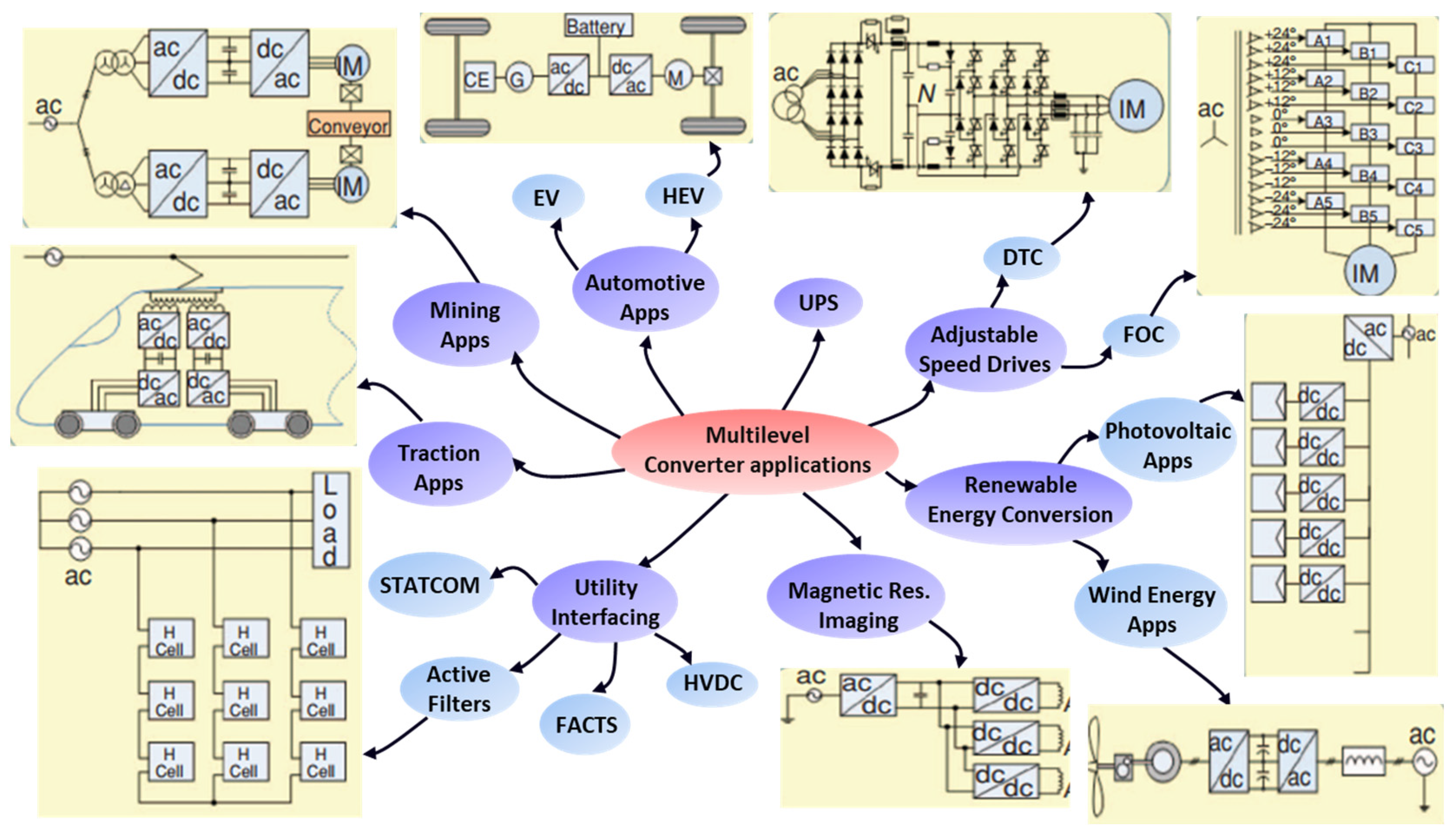
1.1. Background and Context

Multilevel converter topologies have become a practical solution for medium- to high-voltage and high-power applications [1,2]. They have gained significant interest in industry and research due to the persistent problems of conventional two-level power converters, including high harmonic content, poor electromagnetic compatibility, increased voltage stress, and considerable switching losses [3,4,5]. Figure 1 outlines some key applications for multilevel converters [6,7,8]. Multilevel converters generate output voltage waveforms with many output voltage levels to achieve their excellent power quality, which lowers total harmonic distortion (THD), common-mode and derivate voltages (dv/dt), and the need for output filters [9]. Conventional multilevel inverters fall into three main categories: neutral point clamped (NPC), flying capacitor (FC), and cascaded topologies [10]. Table 1 provides a summary comparison of these three conventional topologies. This study only examines the cascaded configuration that employs multiple series-connected single-phase power cells per phase.
A series of module connections allow for high-quality output voltage and input currents, which reduce the size of passive components. It also enables module redundancy. Depending on the application, each power cell is supplied by an isolated DC voltage source, which may be obtained from the following:
A three-phase (or single-phase) input rectifier supplied by a multi-secondary low-frequency transformer [11].
Photovoltaic panels [12].
Power electronic transformers [13].
Ultracapacitors, batteries, or fuel cells [14].
The CHBMI topology is widely used in medium/high voltage and high-power demanding applications for its modularity, scalability, reliability, and improved output power quality. Initially used in medium-voltage applications, it is now vital in renewable energy systems, power electronic transformers (PETs) or solid-state transformers (SSTs), advanced power supply systems, and active filter reactive power compensation [12,13,14]. When the CHBMI phases operate at the same voltage magnitude, the three-phase symmetrical/asymmetrical CHBMI configuration exhibits balanced operation, generating balanced three-phase line-to-neutral (LN) and line-to-line (LL) output voltages and currents.
Figure 2 illustrates the operation of the inverter under ideal conditions, assuming that all power cells have equal DC voltage sources in their input DC links. There has been a significant amount of research conducted by scholars and engineers on cascaded H-bridge multilevel inverters in recent decades [15,16,17,18,19], which can be summarized into four main aspects:
(1)
Improving the output power quality of the CHBMI [20,21,22];
(2)
Reducing the computational burden of its control schemes [23,24,25];
(3)
Balancing and better utilizing the cell DC voltage sources [26,27,28];
(4)
Developing compensation control methods, including fault-tolerant techniques (detection and reconfiguration), to increase its reliability and survivability [29,30,31,32,33,34,35,36,37].
Among these four aspects, the fourth one remains a significant challenge to be addressed and has been a topic of great interest over recent years. The main issue when using a three-phase CHBMI is that it may exhibit an unbalanced operation under certain conditions, reducing the overall system survivability and reliability.

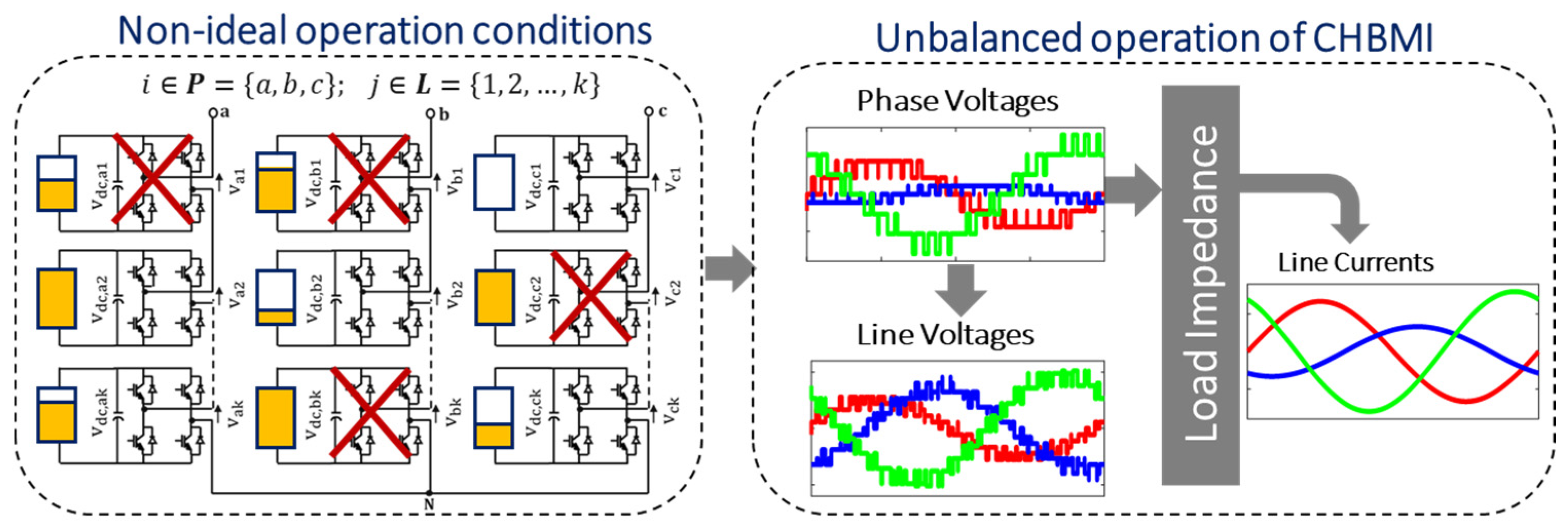
1.2. Major Operational Issue in CHBMI

An unbalanced operation in three-phase CHBMI systems can occur due to various factors, such as the random fluctuation of the DC link voltage supplying the power cells or the failure of at least one H-bridge cell. In grid-connected PV inverter systems, an unbalanced operation of the CHBMI may result due to a lack of coordination between individual MPPTs, the failure of at least one DC–DC converter, or a PV mismatch, or shifting environmental circumstances [38,39]. Battery power systems using CHBMIs may also experience unbalanced operation due to the nonlinear and time-varying nature of the battery’s terminal voltage [40,41,42]. This can lead to imbalances in DC link voltage generation among bridges and affect the normal system operation. The inverter may also exhibit an imbalanced operation when one or more power cells fail in a given phase. Under a faulty cell, the affected power cell’s gate signals are blocked, and its output is bypassed. The failed cell is removed from the circuit, which lowers the system’s reliability and efficiency [29]. Figure 3 illustrates an inverter operation under abnormal conditions, such as unequal DC sources and failed cells (left-hand side of Figure 3). Under all these conditions, the inverter produces unbalanced output voltages (line-to-neutral and line-to-line) and currents (right-hand side of Figure 3), which are not tolerated by the systems where the continuity of the operation is a vital feature.

1.3. Main Contribution

Numerous compensation control solutions have been proposed for CHBMI operation under unbalanced operating conditions in the existing literature. Each operational concern has been studied separately, utilizing independent compensation control schemes, some of which combine software-based and hardware-based strategies. Some control methods aim to maintain balanced three-phase currents on the inverter AC side amidst unequal power distribution among bridge cells. In contrast, others have been developed to rebalance inverter output line voltages, even if their phase voltage remains unbalanced due to failed cells or unequal DC voltage sources. The present study focuses solely on software-based control schemes that modify the modulation stage, and the paper surveys the existing and most popular compensation control schemes suitable for CHBMIs under unbalanced operation. The paper will categorize these control schemes based on their primary compensation purpose. It will provide a comprehensive guide for researchers and field engineers to select appropriate control schemes under the unbalanced operation of CHBMI topologies.

2. Review of Existing Control Methods for CHBMIs with Unequal DC Sources or Failed Cells

2.1. Existing Control Methods for CHBMIs with Unequal DC Voltage Sources

The DC link voltage inequality between different cells on the same phase produces an inter-bridge power imbalance, which may lead to an imbalance between the three phases called inter-phase power imbalance [42]. This is quite a normal phenomenon in large-scale grid-tie PV system configurations (Figure 4). In such a system configuration, both power imbalance issues affect the control and proper operation of CHBMIs in different ways: the inter-bridge power imbalance causes DC link voltage drift, introducing voltage distortion at the AC side [43]. In contrast, inter-phase power imbalance leads to unbalanced three-phase output voltages and currents at the inverter AC side. Two compensation control schemes were previously proposed in the literature to solve both power imbalance issues, as shown in Figure 5, namely the feed-forward control method and the zero-sequence injection methods, respectively.

2.1.1. Feedforward Compensation Control Method

(a)
Operating principle
The basic idea of this approach is to share the power equally on the inverter AC side despite the uneven power distribution on the inverter DC side [43]. This method is based on a feedback mechanism of the cell DC voltage drift to handle the inter-bridge (per-cell) power imbalance issue [44]. The idea behind this compensation mechanism is to distribute the usage of H-bridge cell DC voltage sources of one inverter phase with the same proportion of imbalance. In this way, more- or less-active power is drawn by H-bridge cells according to the system’s imbalance. The principle of this method is illustrated in Figure 6. As it can be seen, the DC voltage error ( v d c , i j * v d c , i j ) is controlled by a PI controller, and the output is utilized to modify the per-unit modulating signal’s amplitude [43]. As a result, the magnitude of each H-bridge cell’s PWM reference signal is adjusted proportionally to the DC link voltage error [44]. Thus, the inverter power switches’ ON and OFF timings are distributed differently in a feedforward compensation, enabling the correction.
(b)
Advantages and disadvantages
The feed-forward control method has many applications in single-phase systems, providing cell DC link voltage drift compensation during the inverter operation [45]. However, using multiple PI controllers in the modulation stage may lead to difficulties in overall system control design and an unsatisfactory dynamic response, potentially leading to poor overall system performance and instability.

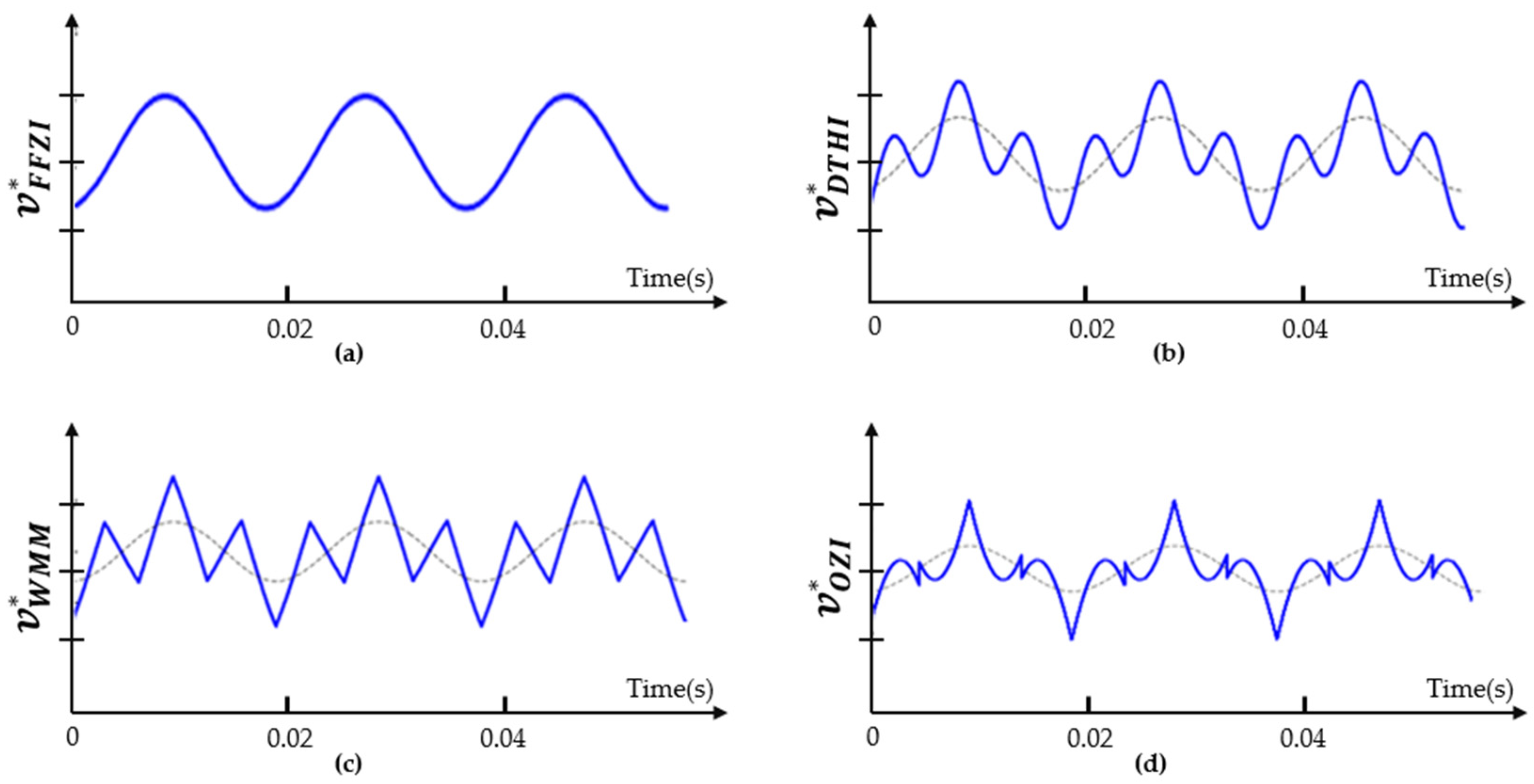
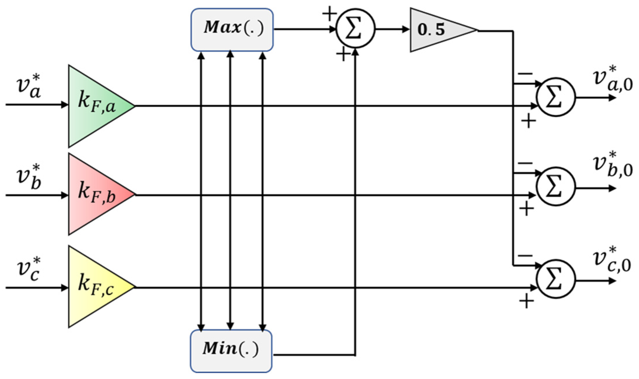
2.1.2. Zero-Sequence Injection Control Method

(a)
Operating principle and implementation scheme
The main purpose of this compensation control approach is to maintain balanced CHBMI output currents, even when the cells experience uneven power distribution ( P a P b P c ) [43,44,45,46,47,48,49,50]. To address the issue of inter-phase power imbalance, injecting zero-sequence components into the pulse-width modulation (PWM) reference signals are necessary, as stated in [43,44,45,46,47,48,49,50]. In this control approach, each inverter phase reference voltage is inversely compensated according to the respective power imbalance ratio in that phase. It considers a given phase’s actual output power P a , b , c   and compares it to the per-phase nominal power P b = P c = P n o m / 3 that should be produced in ideal conditions. The power imbalance ration λ a , b , c in each inverter phase is computed as follows:
λ a , b , c = P a , b , c P n o m / 3
where the average power generation ratio λ ¯ is given using
λ ¯ = λ a + λ b + λ c 3
A block diagram of a control scheme utilizing the zero-sequence injection (ZSI) method is shown in Figure 7, and the modified PWM reference voltage v i 0 * with an injection of a zero-sequence component v Z S I * is given using
v i 0 * = v i * + v Z S I *
The following ZSI methods are the most frequently found methods in the literature [47,48,49]:
  • A fundamental frequency zero-sequence injection (FFZSI) method;
  • A weighted min–max (WMM) method zero-sequence injection method;
  • Double third harmonic (DTHI) injection method;
  • Optimal zero-sequence injection (OZSI) method.
A detailed description of each ZSI method is provided in [49]. Analytical expressions of FFZSI, WMM, DTHI, and OZSI methods are provided in Equations (4)–(7). Their corresponding waveforms under a power-imbalanced case of λ   a = 0.8 ,   λ   b = 1 ,     λ   c = 1 are depicted in Figure 8, for illustrative purposes.
v F F Z S I * = 2 V 0 cos ( ω t + θ )
V 0 = 6 3 ( λ a + λ b + λ c ) V   g
v W M M * = 1 2 m i n λ ¯ λ a v a + λ ¯ λ b v b   + λ ¯ λ c v c   1 2 m a x λ ¯ λ a v a + λ ¯ λ b v b                     + λ ¯ λ c v c  
v D T H I * = v F F Z S I * 1 6 2 V + cos 3 ω t + 3 α 1 6 2 V 0 cos 3 ω t + 3 θ
The first term in Equation (7) denotes the fundamental frequency component, v F F Z S I * . The magnitude of the second term is the 1/6 third harmonic injection of the positive sequence of the inverter output voltage v a , and the last term’s magnitude is the 1/6 third harmonic injection of v F F Z S I * . The positive-to-negative zero-crossing angle β and the size of the square wave v p * , both given in Equation (8), are necessary parameters to define when using the OZSI method:
v p * = 6 V + c o s 2 β + α 1     2 2 π V 0 cos θ α     2 π V + 8 s i n ( β + α )
where V + and α are the third harmonic’s rms value and its phase angle, and V 0 and θ are the third harmonic’s rms value and its phase angle for the fundamental frequency’s zero-sequence. The fixed-point iterative approach described in [49] can be used to calculate α and β . The following two conditions must be satisfied when using the OZSI method: (i) its fundamental frequency component must be of a magnitude comparable to that of the FFZI, and (ii) its harmonic frequency component must cause the inverter voltage to peak as low as possible [47,48,49].
(b)
Advantages and disadvantages
The fundamental frequency zero-sequence injection, weighted min–max zero-sequence injection, and double third harmonic injection approaches enable simple digital implementation. It has been found that the FFZI approach can only rebalance 5% of all conceivable power imbalance situations [49]. The DTHI and WMM methods can produce balanced three-phase output currents under 15% of all possible power imbalance cases [49]. However, it has been discovered that there may be better methods for severe power imbalance cases. In such cases, the target of maintaining balanced inverter output currents using these methods may fail because their fundamental frequency component’s root mean square (RMS) values may be expected to increase with the severity of the power imbalance, making them less effective [49].
An optimal zero-sequence injection (OZSI) method has been proposed to tackle a severe power imbalance case [47,48,49]. This method fully exploits the voltage overhead that the inverter provides under the severity of power imbalance distribution among the bridges. Despite being one of the most sophisticated existing ZSI-based methods, it can only cope with up to 20% of potential power imbalance cases [49]. More importantly, it is less effective under CHBMI operation with failed cells.

2.1.3. State-of-the-Art Other Compensation Control Approaches for Unbalanced CHBMI Operation with Unequal DC Voltage Sources

Alternative modulation techniques have been proposed to maintain balanced line-to-line output voltages, besides the zero-sequence injection methods. Neutral Voltage Modulation (NVM) was proposed to address DC voltage imbalance in CHBMIs while extending the inverter phases’ linear region during the operation [51]. The conventional Neutral Voltage Modulation (NVM) technique encounters certain limitations concerning the neutral voltage constraints, which can restrict the maximum linear modulation index under severe unbalanced DC source conditions. To overcome this challenge, an enhanced NVM method has been introduced for symmetrical and asymmetrical three-phase multilevel cascaded inverter configurations [52]. A State Transition (ST)-based Space Vector Pulse Width Modulation (PWM) technique under CHBMI operation with unbalanced DC sources was proposed in [53]. However, selecting appropriate switching sequences when the ST-PWM approach increases its complexity in digital implementation, especially for inverters with higher voltage levels. An inter-phase and inter-bridge power control algorithm based on the ST-PWM approach for CHBMI with unbalanced DC sources was proposed in [54], offering better output waveforms with more straightforward calculations.

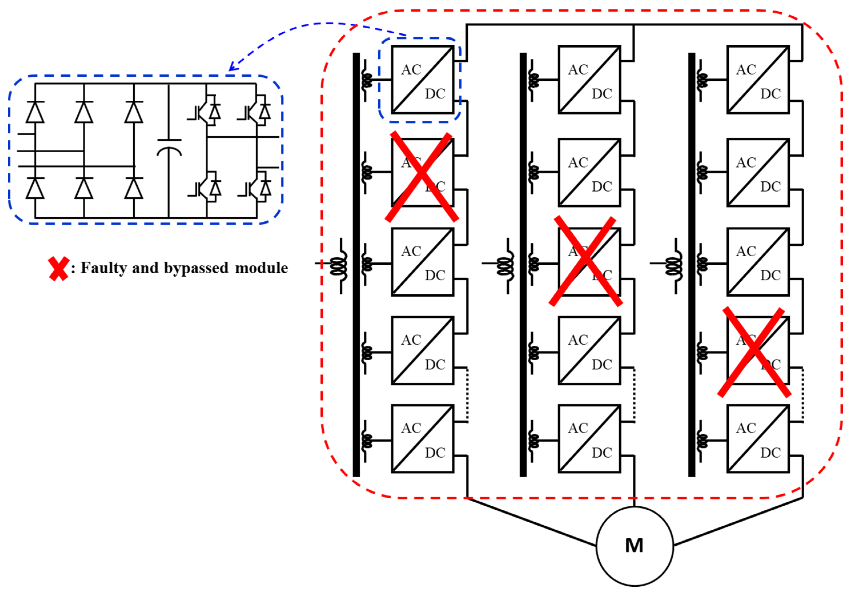
2.2. Existing Control Methods for CHBMI Operation with Failed Cells

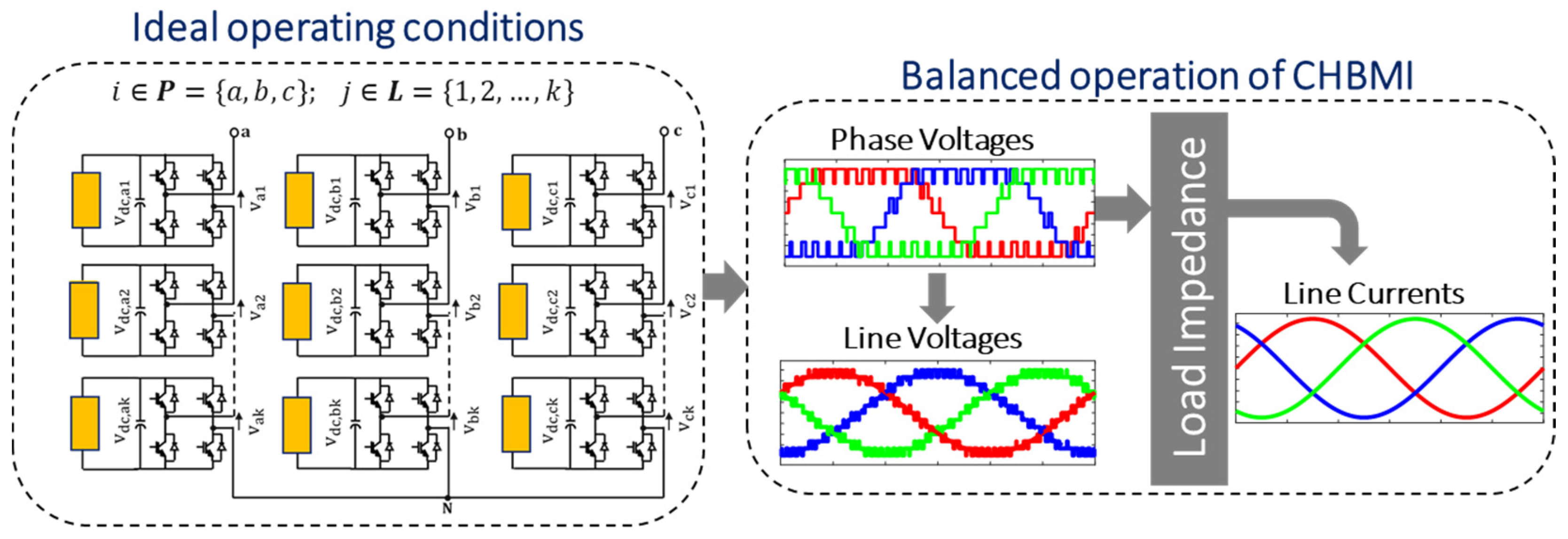
2.2.1. Basic Considerations

CHBMIs can operate continuously, even if one or more power cells fail. This is accomplished through implementing appropriate “fault-tolerant” control strategies, which have been extensively proposed and discussed in the literature [55,56,57]. These fault-tolerant control methods are regarded as exciting solutions for the uninterrupted operation of variable-frequency drive (VFD) systems (Figure 9), even when some cells have failed [58]. Let us consider in this case a CHBMI-VFD system with k N , i -series connected H-bridge power cells in the phase i , of a three-phase system. Each cell is supplied by a DC voltage v d c , i j = v d c , such that v d c = 1 ·   p u for healthy cells and v d c = 0 for failed cells. In balanced conditions, the phase shift between phase voltages is θ 0 , i = i 1 2 π 3 ,   i K = a = 1 ,   b = 2 ,   c = 3 .
u a b c = 1 1 0 0 1 1 1 0 1 · v a b c
v a b c = v a   v b   v c T ;   u a b c = u a b   u b c   u c a T
Each phase voltage can be expressed as a complex number:
v i = x i + j   y i ,   i K
In that case, the total perceived DC link voltage per phase is given using
V d c , i = k i . v d c
Let us assume there are ϵ i failed H-bridge cells on phase i , such that ϵ i < k N , i . In that case, the system becomes imbalanced, and the perceived maximum phase voltage in the affected phase is given using
V m a x , i F = k N , i ϵ i 3 2 v d c
Figure 10a shows an illustration of a 15-cell CHB-VFD in which no cells are bypassed. In normal mode, 100% of the modules are in use, and 100% of the original voltage is available. Figure 10b illustrates the voltage phasor diagram of the same 15-cell CHB-VFD when two cells are bypassed in phase A without the compensation fault-tolerant control method.
The existing fault-tolerant control methods can be broadly categorized into two groups (Figure 11): those that modify the software, i.e., the inverter control/modulation algorithms, and those that adjust the hardware of the inverter topology after fault diagnosis [56,57,58]. This paper only presents and discusses carrier-based fault-tolerant control techniques, particularly the conventional neutral-shift and peak-reduction control methods.

2.2.2. Conventional Neutral-Shift Control Method

(a)
Operating principle and implementation scheme
P. Hammond introduced the neutral-shift control method in [36]. This fault-tolerant control technique allows for moving the inverter neutral point from its initial position to a new one so that even if the inverter’s line-to-neutral inverter voltages are unbalanced, its phase-to-phase voltages will be kept balanced [59,60,61,62]. This is achieved by adequately modifying the inverter PWM reference phase voltage angles [36]. The principle of the neutral-shift method is illustrated in Figure 12a. The key idea is to determine the values of the inverter phase voltage angles α ,   β and γ so that the points A, B, and C will form an equilateral triangle even with faulty cells. The equivalence of the inverter LL voltage amplitudes is given in (14). These equations can be derived from real and imaginary parts of voltage vectors as given in (15)
v b a = v a c = v b c
( x b x c ) 2 + y b 2 = ( x c x a ) 2 + y c 2                             ( x b x c ) 2 + y b 2 = ( x c x b ) 2 + ( y c y b ) 2   v b 2 = x b 2 + y b 2                                                                                                   v c 2 = x c 2 + y c 2                                                                                                
The inverter voltage phase angles under faulty cells are computed using
θ a b = a r c t a n y b x b
θ a c = a r c t a n y c x c
θ b c = 360 ( α + β )
Figure 12b illustrates the voltage phasor diagram of the same 15-cell CHB-VFD when two cells are bypassed in phase A under the neutral-shift strategy. As illustrated, the phase angles of the 15-cell CHB-VSI have been adjusted so that phase A is displaced from phase B and from phase C by 132.5°, instead of the normal 120°. In these conditions, the input is LL. This will result in balanced line voltages (obviously with reduced magnitude).
(b)
Advantages and disadvantages
In the three-phase CHBMI systems, the star point is usually floating and is not connected to the ground of the system. The neutral-shift strategy takes advantage of this fact because the neutral point can be shifted to a new position by properly adjusting the inverter reference phase voltage angles without additional system hardware. This results in a balanced output LL voltage and maintains continuous and stable operation of CHBMI, even if LN voltages remain unbalanced. However, when using the neutral-shift method, the numerical resolution of Equation (15) has a complex implementation in digital platforms. It has been found that these equations do not have solutions in certain fault conditions [63]. More importantly, the conventional neutral-shift control strategy does not ensure the operation of the inverter within its linear region limits under faulty cells.
The fault-tolerant-based neutral-shift strategy can be subdivided into two groups based on the type of modulation scheme used. The first group uses carrier-based PWM methods, implemented on phase-shifted (PS) and phase-disposition (PD) PWM methods [61,62,63]. The second group uses vector-based methods using space vector PWM techniques [64,65,66]. In SVPWM methods, the inverter switching vectors are given in stationary orthogonal reference frame α β , and the inverter space vector diagram has integer entries. It is demonstrated that the space vector diagram will change its shape and become an irregular six-sided polygon when operating under unbalanced conditions. However, many voltage vectors still exist under an unbalanced operation of the inverter due to redundant switching states that can be explored to generate a three-phase balanced line-to-line voltage at the inverter AC side. This approach offers great flexibility in optimizing switching patterns compared to the carrier-based neutral-shift strategies, as the reference vectors are consistently found to be selected in the location nearest the voltage states.

2.2.3. Peak-Reduction Fault-Tolerant Control Strategy

(a)
Operating principle and implementation scheme
To address the limitations of the neutral-shift control technique under carrier-based PWM methods, researchers have proposed peak-reduction fault-tolerant methods in the literature [63]. These methods involve adjusting the reference phase voltage amplitudes to balance the output line voltages and maximize the utilization of the remaining operative cells. The approach is to inject a dynamic average min–max homopolar component into the PWM reference voltages, modifying the new reference magnitude proportionally to unequally gain k F , i , calculated as given in (17). The implementation block diagram of the conventional peak-reduction control method is illustrated in Figure 13.
k F , i = k N , i k N , i ϵ i
(b)
Advantages and disadvantages
Compared to the conventional neutral strategy, the traditional peak-reduction fault-tolerant control method enables straightforward digital implementation, and it is suitable to prevent the inverter from entering the overmodulation region under faulty conditions. However, although this method is simple to implement, it comes at the expense of increasing inverter output waveform distortions. To reduce these distortions, another method is proposed in [63] that introduces a feedback loop with an integrator to improve the quality of inverter output voltage waveforms under unbalanced operation.

3. Suggested Future Trends

Selected operational features are used in Table 2 to summarize and classify the studied control method based on their compensation requirements.
According to Table 2, it is essential to acknowledge that, while existing control methods have made significant progress in enabling stable and reliable operation of multilevel cascaded H-bridge modular inverters (CHBMIs) under challenging conditions such as failed cells or unequal DC voltage sources, several limitations and research areas warrant further investigation. The following are some of the critical issues and challenges to address.
(i)
Universal compensation control technique: There is a gap in the existing literature regarding control methods that simultaneously address unequal DC voltage sources and failed cells in CHBMI topologies. A search of the literature did not release a unified and generalized compensation control technique that can rebalance both the CHBMI output LL voltages and currents at any unequal DC source conditions and simultaneously deal with the failed cells.
(ii)
Improved neutral-shift compensation control schemes with SVPWM approach: A thorough search of the literature has revealed the lack of a neutral-shift-based space vector pulse-width modulation (SVPWM) control scheme for the control of a cascaded H-bridge multilevel inverter (CHBMI) operating with fractional DC source voltages and where the inverter space vector diagram in α β -plan is formed with non-integer phase leg magnitudes ( v i = j = 1 k v d c , i j ⅅ). This results in a highly complex control problem that existing neutral-shift-based SVPWM control methods cannot effectively address. This critical research gap must be addressed in the future by developing new analyses and control/modulation approaches optimized for such scenarios.
(iii)
Advanced control schemes: Recently, fault-tolerant and compensation strategies using model predictive control, including data-driven methods, have been suggested in the literature for CHBMIs under unbalanced operation [67,68,69]. The model predictive control methods are becoming increasingly popular in the advanced control of inverters. These methods have proven effective in preventing and compensating for issues related to unequal DC sources or failed cells. At the same time, they remain immune to system dynamics, such as changes in input and other parameters. However, a search of the literature did not release a model predictive control scheme with fault-tolerant capabilities considering the inverter operation with random fluctuations of DC source voltages ( v d c , i j ] 0   ,   1 [   p . u ) . Under these conditions, the inverter phasor in the α β -plan may have non-integer entries, and some states may disappear or slightly move within the phasor limits, depending on the severity of the unequal condition of DC sources. This adds high complexity to the control process. Existing model predictive-based compensation control methods may not be directly applicable or optimized for such scenarios.
(iv)
Harmonics and disturbance rejection: A harmonic analysis of existing compensation control methods for cascaded H-bridge inverter operation under unequal DC voltage sources and failed cells should be better conducted. The CHBMI output voltage and current spectra are adjusted using the investigated compensation control methods. Because the locations of the modified harmonics are unknown, it is crucial for the completeness of the design to analytically calculate these harmonics in the frequency domain, assess their effects on the power transmission line, and evaluate the type of stresses they are generating into the system where the CHBMI is involved. Mitigating harmonics and their related disturbances under the operation of CHBMIs with unequal DC voltage sources or failed cells is crucial for the overall system’s output power quality performances. Improving the existing compensation control methods to address this aspect more effectively is an ongoing research area.
(v)
Efficiency and thermal management: Achieving high efficiency and effective thermal management under unequal DC voltage sources or failed cells is critical for CHBMI systems, especially in high-power applications. Further work is needed to optimize existing compensation control methods for efficiency and thermal performance. In addition, inverter switching, and conduction losses are greatly influenced by using a given compensation control method. Consequently, power device losses and the overall CHBMI efficiency should be analyzed in depth in the view of practical applications.
(vi)
Simple and optimized switching strategy: The existing compensation control strategies are typically implemented using multicarrier-based or space-vector-based PWM techniques. Multi-carrier-based techniques are easy to implement but must guarantee optimized switching patterns and have high computation costs. On the other hand, SV PWM-based techniques offer flexibility in optimizing the switching patterns but require significant development efforts when the number of voltage levels produced by the inverter is large. The use of simplified and optimized modulation techniques during the system’s unbalanced operation will be a promising control solution. In recent years, single-carrier (SC-PWM) PWM methods have become more prevalent in multilevel converter topology control systems [70,71,72,73]. Compared to traditional multi-carrier PWM techniques or space vector-based techniques, they present a straightforward real-time implementation while achieving acceptable harmonic performances [73]. Developing compensation control methods based on an SC-PWM algorithms is needed.

4. Conclusions

This paper has reviewed and categorized the most popular compensation control techniques suitable for cascaded H-bridge multilevel inverter operation under unequal DC sources or failed cells. The study has primarily focused on carrier-based compensation control techniques, as they are widely adopted and preferred due to their versatility and ease of implementation with minimal modifications required for use in various applications. Particular attention has been paid to feed-forward and zero-sequence injection control methods to mitigate the issue of unequal DC voltage sources or unbalanced power distribution. Additionally, special attention has been paid to neutral-shift and peak-reduction control methods for dealing with the problems of faulty cells in inverter topologies. These control techniques ensure stable and continuous CHBMI operation by maintaining balanced output line-to-line voltages or currents even if the line-to-neutral voltages remain unbalanced due to unequal DC voltage sources or failed cells. In practice, the balanced three-phase inverter output currents are needed to prevent tripping the differential protective functions #87 of protective relays [74]. The balanced three-phase inverter output voltages allow synchronization between the inverter and load, which is permitted by protection function #25 [74]. The paper has presented a detailed description of each control method, highlighted their significance, and listed some of their disadvantages. The paper also explores potential future trends and research directions for improving existing control schemes or developing innovative solutions. One of the proposed solutions is the vacuum current literature, which can address both uneven DC voltage sources and failed cells simultaneously. The proposed study has solely focused on the conventional cascaded H-bridge multilevel converters (CHBMICs). However, it is crucial to discuss the suitability and applicability of the compensation control methods presented in the study for other new topologies, such as Packed U-cell inverters (PUC) and Packed E-Cell Inverters (PEC) [75,76,77]. These topologies could replace the conventional CHBMICs and offer better performances for grid-tie applications and variable-frequency drive systems. By exploring the feasibility of these alternatives, researchers can better understand how to optimize the compensation control methods for various multilevel converter topologies, ultimately resulting in more efficient and effective industrial power electronic conversion systems.

Author Contributions

Conceptualization and overall paper organization: P.M.L. and J.S.-M. Theoretical and numerical validation methodologies: P.M.L., J.S.-M. and J.M.N.-Y. Numerical simulations and simulation data processing: P.M.L. Results analyses: P.M.L. and J.S.-M. Writing—original draft preparation and writing: P.M.L. Review and editing: J.S.-M. and M.L.D. Overall project supervision: J.S.-M. and J.M.N.-Y. All authors have read and agreed to the published version of the manuscript.

Funding

This research received no external funding.

Conflicts of Interest

The authors declare no conflicts of interest.

References

  1. Bose, B.K. The past, present and future of power electronics. IEEE Ind. Electron. Mag. 2009, 3, 7–14. [Google Scholar] [CrossRef]
  2. Rodriguez, J.; Bernet, S.; Wu, B.; Pont, J.; Kouro, S. Multilevel Voltage-Source-Converter Topologies for Industrial Medium-Voltage Drives. IEEE Trans. Ind. Electron. 2007, 54, 2930–2945. [Google Scholar] [CrossRef]
  3. Bana, P.R.; Panda, K.P.; Naayagi, R.T.; Panda, G. Recently developed reduced switch multilevel inverter for renewable energy integration and drives application: Topologies, comprehensive analysis, and comparative evaluation. IEEE Access 2019, 7, 54888–54909. [Google Scholar] [CrossRef]
  4. Salem, A.; Khang, H.V.; Robbersmyr, K.G.; Norambuena, M.; Rodriguez, J. Voltage source multilevel inverters with reduced device count: Topological review and novel comparative factors. IEEE Trans. Power Electron. 2021, 36, 2720–2747. [Google Scholar] [CrossRef]
  5. Kouro, S.; Malinowski, M.; Gopakumar, K.; Pou, J.; Franquelo, L.G.; Wu, B.; Rodriguez, J.; Pérez, M.A.; Leon, J.I. Recent advances and industrial applications of multilevel converters. IEEE Trans. Ind. Electron. 2010, 57, 2553–2580. [Google Scholar] [CrossRef]
  6. Carrasco, J.M.; Franquelo, L.G.; Bialasiewicz, J.T.; Galvan, E.; Portillo Guisado, R.C.; Prats, M.M.; Leon, J.I.; Moreno Alfonso, N. Power-electronic systems for the grid integration of renewable energy sources: A survey. IEEE Trans. Ind. Electron. 2006, 53, 1002–1016. [Google Scholar] [CrossRef]
  7. Perez, M.A.; Bernet, S.; Rodriguez, J.; Kouro, S.; Lizana, R. Circuit topologies, modeling, control schemes, and applications of modular multilevel converters. IEEE Trans. Power Electron. 2015, 30, 4–17. [Google Scholar] [CrossRef]
  8. Franquelo, L.G.; Rodriguez, J.; Leon, J.I.; Kouro, S.; Portillo, R.; Prats, M.A. The age of multilevel converters arrives. IEEE Trans Ind Electron. 2008, 2, 28–39. [Google Scholar] [CrossRef]
  9. Wang, C.; Li, Y. A Survey on Topologies of Multilevel Converters and Study of Two Novel Topologies. In Proceedings of the IEEE 6th International Power Electronics and Motion Control Conference, Wuhan, China, 17–20 May 2009; pp. 860–865. [Google Scholar]
  10. Rahman, S.; Meraj, M.; Iqbal, A.; Prathap-Reddy, B.; Khan, I. A Combinational Level-Shifted and Phase-Shifted PWM Technique for Symmetrical Power Distribution in CHB Inverters. IEEE J. Emerg. Sel. Top. Power Electron. 2023, 11, 932–941. [Google Scholar] [CrossRef]
  11. Peng, X.; He, X.; Han, P.; Lin, X.; Shu, Z.; Gao, S. Sequence pulse modulation for voltage balance in a cascaded H-bridge rectifier. J. Power Electron. 2017, 17, 664–673. [Google Scholar] [CrossRef]
  12. Li, X.; Chai, J.; Li, M.; Li, L.; You, R. A Grid Frequency Support Control Strategy of the Three Phase Cascaded H-Bridge Based Photovoltaic Generation System. IEEE Access 2022, 10, 56974–56984. [Google Scholar] [CrossRef]
  13. Tian, J.; Hu, D.; Zhou, C.; Yang, Y.; Wu, W.; Mao, C.; Wang, D. Individual DC voltage balance control for cascaded Hbridge electronic power transformer with separated DC-link topology. IEEE Access 2019, 7, 38558–38567. [Google Scholar] [CrossRef]
  14. Rauf, A.M.; Abdel-Monem, M.; Hegazy, G.O. A Review on Multilevel Converters for Efficient Integration of Battery Systems in Stationary Applications. Energies 2023, 16, 4133. [Google Scholar] [CrossRef]
  15. Mouselinos, T.P.; Tatakis, E.C. Multilevel inverters: A survey of limitations and recommended problem-solving techniques. In Proceedings of the 21st European Conference on Power Electronics and Applications (EPE ’19 ECCE Europe), Genova, Italy, 3–5 September 2019; pp. 1–10. [Google Scholar]
  16. Admed, M. Classical Control for Unequal DC Sources Five-Level Inverter-Based SHE Technique. Energies 2020, 13, 4715. [Google Scholar] [CrossRef]
  17. Akhmetov, Z.; Hammami, M.; Grandi, G.; Ruderman, A. On PWM Strategies and Current THD for Single- and Three-Phase Cascade H-Bridge Inverters with Non-Equal DC Sources. Energies 2019, 12, 441. [Google Scholar] [CrossRef]
  18. Hamza, H.; Song-Manguelle, J.; Lingom, P.M.; Nyobe-Yome, J.; Doumbia, M.L. A Review of Fault-Tolerant Control Methods for Cascaded H-Bridge Multilevel Inverters. In Proceedings of the 14th IEEE International Conference on Power Electronics and Drive Systems (PEDS), Montreal, QC, Canada, 7–10 August 2023. [Google Scholar]
  19. Xiong, J.; Zhou, F.; Li, Q. Soft-switching modulation of the multilevel cascaded H-bridge inverter under DC source fault. IET Gener. Transm. Distrib. 2021, 15, 1337–1347. [Google Scholar] [CrossRef]
  20. Yang, K.; Lan, X.; Zhang, Q.; Tang, X. Unified selective harmonic elimination for cascaded Hbridge asymmetric multilevel inverter. IEEE J. Emerg. Sel. Top. Power Electron. 2018, 6, 2138–2146. [Google Scholar] [CrossRef]
  21. Ghazanfari, A.; Mokhtari, H.; Firouzi, M. Simple voltage balancing approach for CHB multilevel inverter considering low harmonic content based on a hybrid optimal modulation strategy. IEEE Trans. Power Deliv. 2012, 27, 2150–2158. [Google Scholar] [CrossRef]
  22. Townsend, C.D.; Summers, T.J.; Betz, R.E. Impact of practical issues on the harmonic performance of phase-shifted modulation strategies for a cascaded H-bridge statcom. IEEE Trans. Ind. Electron. 2013, 61, 2655–2664. [Google Scholar] [CrossRef]
  23. Kim, I.; Chan, R.; Kwak, S. Model predictive control method for CHB multi-level inverter with reduced calculation complexity and fast dynamics. IET Electr. Power Appl. 2017, 11, 784–792. [Google Scholar] [CrossRef]
  24. Zhang, Y.; Wu, X.; Yuan, X.; Wang, Y.; Dai, P. Fast model predictive control for multilevel cascaded Hbridge STATCOM with polynomial computation time. IEEE Trans. Ind. Electron. 2016, 63, 5231–5243. [Google Scholar]
  25. Chan, R.; Kwak, S. Improved Finite-Control-Set Model Predictive Control for Cascaded H-Bridge Inverters. Energies 2018, 11, 355. [Google Scholar] [CrossRef]
  26. Shu, Z.; He, X.; Wang, Z.; Qiu, D.; Jing, Y. Voltage balancing approaches for diode-clamped multilevel converters using auxiliary capacitor-based circuits. IEEE Trans. Power Electron. 2013, 28, 2111–2124. [Google Scholar] [CrossRef]
  27. Wang, Q.; Liu, K.; Wang, K.; Qin, L.; Zhang, J.; Pu, Q. Fast capacitor voltage balancing strategy based on system history operation information for MMC. IET Gener. Transm. Distrib. 2019, 13, 1104–1109. [Google Scholar] [CrossRef]
  28. Wang, L.; Wu, Q.; Tang, W. Energy Balance Control of a Cascaded Multilevel Inverter for Standalone Solar Photovoltaic Applications. Energies 2017, 10, 1805. [Google Scholar] [CrossRef]
  29. Lingom, P.M.; Song-Manguelle, J.; Betoka-Onyama, S.P.; Nyobe-Yome, J.M.; Doumbia, M.L. A Power Quality Assessment of Electric Submersible Pumps Fed by Variable Frequency Drives under Normal and Failure Modes. Energies 2023, 16, 5121. [Google Scholar] [CrossRef]
  30. Mirafzal, B. Survey of Fault-Tolerance Techniques for Three-Phase Voltage Source Inverters. IEEE Trans. Ind. Electron. 2014, 61, 5192–5202. [Google Scholar] [CrossRef]
  31. Gao, Z.; Cecati, C.; Ding, S.X. A Survey of Fault Diagnosis and Fault-Tolerant Techniques—Part I: Fault Diagnosis with Model-Based and Signal-Based Approaches. IEEE Trans. Ind. Electron. 2015, 62, 3757–3767. [Google Scholar] [CrossRef]
  32. Gautam, S.P.; Jalhotra, M.; Sahu, L.K.; Kumar, M.R.; Gupta, K.K. A Survey on Fault Tolerant and Diagnostic Techniques of Multilevel Inverter. IEEE Access 2023, 11, 60866–60888. [Google Scholar] [CrossRef]
  33. Lingom, P.; Song-Manguelle, J.; Mon-Nzongo, D.L.; Lingom, P.; Flesch, R.C.C.; Jin, T. Analysis and control of PV cascaded H-bridge multilevel inverter with failed cells and changing meteorological conditions. IEEE Trans. Power Electron. 2021, 36, 1777–1789. [Google Scholar] [CrossRef]
  34. Song, Y.; Wang, B. Survey on reliability of power electronic systems. IEEE Trans. Power Electron. 2013, 28, 591–604. [Google Scholar] [CrossRef]
  35. Lezana, P.; Ortiz, G. Extended operation of cascade multicell converters under fault condition. IEEE Trans. Ind. Electron. 2009, 56, 2697–2703. [Google Scholar] [CrossRef]
  36. Hammond, P.W. Enhancing the reliability of modular medium voltage drives. IEEE Trans. Ind. Electron. 2002, 49, 948–954. [Google Scholar] [CrossRef]
  37. Lingom, P.M.; Song-Manguelle, J.; Nyobe-Yome, J.M.; Mon-Nzongo, D.L.; Jin, T.; Doumbia, M.L. Control of a Cascaded H-bride Multilevel Inverter with Failed cells for Grid-Connected Application. In Proceedings of the 10th IEEE International Symposium on Power Electronics for Distributed Generation Systems, Xi’an, China, 3–6 June 2019. [Google Scholar]
  38. Lingom, P.; Song-Manguelle, J.; Betoka-Onyama, S.P.; Doumbia, M.L.; Nyobe-Yome, J.M.; Jin, T. A generalized modulation strategy for cascaded H-bridge Multilevel Inverter under Unequal DC Sources. In Proceedings of the IEEE Energy Conversion Congress and Exposition (ECCE), Detroit, MI, USA, 9–13 October 2022. [Google Scholar]
  39. Kumar, A.; Verma, V. Performance enhancement of single-phase grid-connected PV system under partial shading using cascaded multilevel converter. IEEE Trans. Ind. Appl. 2018, 54, 2665–2676. [Google Scholar] [CrossRef]
  40. Tolbert, L.M.; Chiasson, J.N.; McKenzie, K.J.; Zhong, D. Control of cascaded multilevel converters with unequal voltage sources for HEVs. In Electric Machines and Drives Conference, Proceedings of the IEMDC’03, Xi’an, China, 3–6 June 2019; IEEE International: New York, NY, USA, 2003; pp. 663–669. [Google Scholar]
  41. Marzo, I.; Sanchez-Ruiz, A.; Barrena, J.A.; Abad, G.; Muguruza, I. Power Balancing in Cascaded H-Bridge and Modular Multilevel Converters Under Unbalanced Operation: A Review. IEEE Access 2021, 9, 110525–110543. [Google Scholar] [CrossRef]
  42. Lamb, J.; Mirafzal, B. An Adaptive SPWM Technique for Cascaded Multilevel Converters with Time-Variant DC Sources. IEEE Trans. Ind. Appl. 2016, 52, 4146–4156. [Google Scholar] [CrossRef]
  43. Rivera, S.; Kouro, S.; Wu, B.; Leon, J.; Rodriguez, J.; Franquelo, L. Cascaded H-Bridge multilevel converter multistring topology for Large Scale Photovoltaic System. In Proceedings of the 2011 IEEE International Symposium on Industrial Electronics, Gdansk, Poland, 27–30 June 2011; pp. 1837–1844. [Google Scholar]
  44. Xiao, B.; Hang, L.; Mei, J.; Riley, C.; Tolbert, L.M.; Ozpineci, B. Modular cascaded h-bridge multilevel PV inverter with distributed MPPT for grid-connected applications. IEEE Trans. Ind. Appl. 2015, 51, 1722–1731. [Google Scholar] [CrossRef]
  45. Yu, Y.; Konstantinou, G.; Townsend, C.D. Power balance of cascaded H-bridge multilevel converters for large-scale photovoltaic integration. IEEE Trans. Power Electron. 2016, 1, 292–303. [Google Scholar] [CrossRef]
  46. Yu, Y.; Konstantinou, G.; Hredzak, B.; Agelidis, V.G. On extending the energy balancing limit of multilevel cascaded H-bridge converters for largescale photovoltaic farms. In Proceedings of the 2013 Australasian Universities Power Engineering Conference (AUPEC), Hobart, Australia, 29 September–3 October 2013; pp. 1–6. [Google Scholar]
  47. Yu, Y.; Konstantinou, G.; Hredzak, B.; Agelis, V. Operation of cascaded H-bridge multilevel converters for large-scale photovoltaic power plants under bridge failures. IEEE Trans. Ind. Electron. 2015, 62, 7228–7236. [Google Scholar] [CrossRef]
  48. Xue, H.; He, J. A Simplified Power Balance Strategy for Three-Phase Cascaded H-bridge Photovoltaic Inverter. In Proceedings of the 2022 IEEE Energy Conversion Congress and Exposition (ECCE), Detroit, MI, USA, 9–13 October 2022; pp. 1–6. [Google Scholar]
  49. Yu, Y.; Konstantinou, G.; Townsend, C.D.; Agelis, V. Comparison of zero-sequence injection methods in cascaded h-bridge multilevel converters for large-scale photovoltaic integration. IET Renew. Power Gen. 2017, 11, 603–613. [Google Scholar] [CrossRef]
  50. Summers, T.J.; Betz, R.E.; Mirzaeva, G. Phase leg voltage balancing of a cascaded H-Bridge converter based STATCOM using zero sequence injection. In Proceedings of the 2009 13th European Conference on Power Electronics and Applications, Barcelona, Spain, 8–10 September 2009; pp. 1–10. [Google Scholar]
  51. Cho, Y.; Labella, T.; Lai, J.S.; Senesky, M.K. A Carrier-Based Neutral Voltage Modulation Strategy for Multilevel Cascaded Inverters under Unbalanced DC Sources. IEEE Trans. Ind. Electron. 2014, 61, 625–636. [Google Scholar] [CrossRef]
  52. Kim, J.; Cho, Y. Neutral Voltage Modulation for Maximizing the Linear Modulation Region and Limp-Home Mode Operation of Multilevel Cascaded Inverters under DC-Link Imbalance Conditions. IEEE Access 2022, 10, 13515–13524. [Google Scholar] [CrossRef]
  53. Ye, Z.B.; Wang, T.T. A PWM strategy based on state transition for cascaded H-bridge inverter under unbalanced DC sources. IEEE J. Emerg. Sel. Top. Power Electron. 2019, 8, 1686–1700. [Google Scholar] [CrossRef]
  54. Xia, Z.; Wu, Q.; Ye, Z.; Yu, D.; Zhu, L.; Hu, W. A Novel DC-Power Control Method for Cascaded Converter under DC Voltage-Imbalance Condition. J. Electr. Comput. Eng. 2022, 37, 12301–12315. [Google Scholar] [CrossRef]
  55. Lezana, P.; Pou, J.; Meynard, T.A.; Rodriguez, J.; Ceballos, S.; Richardeau, F. Survey on fault operation on multilevel inverters. IEEE Trans. Ind. Electron. 2010, 57, 2207–2218. [Google Scholar] [CrossRef]
  56. Zhang, W.; Xu, D.; Enjeti, P.N.; Li, H.; Hawke, J.T.; Krishnamoorthy, H.S. Survey on fault-tolerant techniques for power electronic converters. IEEE Trans. Power Electron. 2014, 29, 6319–6331. [Google Scholar] [CrossRef]
  57. Rahimpour, S.; Husev, O.; Vinnikov, D.; Kurdkandi, N.V.; Tarzamni, H. Fault management techniques to enhance the reliability of power electronic converters: An overview. IEEE Access 2023, 11, 13432–13446. [Google Scholar] [CrossRef]
  58. Salimian, H.; Iman-Eini, H. Fault-tolerant operation of three-phase cascaded H-bridge converters using an auxiliary module. IEEE Trans. Ind. Electron. 2017, 64, 1018–1027. [Google Scholar] [CrossRef]
  59. Kang, J.-W.; Hyun, S.-W.; Ha, J.-O.; Won, C.-Y. Improved Neutral-Point Voltage-Shifting Strategy for Power Balancing in Cascaded NPC/H-Bridge Inverter. Electronics 2018, 7, 167. [Google Scholar] [CrossRef]
  60. Rodriguez, J.; Hammond, P.W.; Pontt, J.; Musalem, R.; Lezana, P.; Escobar, M.J. Operation of a medium-voltage drive under faulty conditions. IEEE Trans. Ind. Electron. 2005, 52, 1080–1085. [Google Scholar] [CrossRef]
  61. Kim, S.; Lee, J.; Lee, K. A modified level-shifted PWM strategy for fault-tolerant cascaded multilevel inverters with improved power distribution. IEEE Trans. Ind. Electron. 2016, 63, 7264–7274. [Google Scholar] [CrossRef]
  62. Lopez, O.; Komrska, T.; Alvarez, J.; Adam, J. Post-Fault Operation Strategy for Cascaded H-Bridge Inverters Driving a Multiphase Motor. IEEE Trans. Ind. Electron. 2024, 71, 4309–4319. [Google Scholar] [CrossRef]
  63. Carnielutti, F.; Pinheiro, H.; Rech, C. Generalized carrier-based modulation strategy for cascaded multilevel converters operating under fault conditions. IEEE Trans. Ind. Electron. 2012, 59, 679–689. [Google Scholar] [CrossRef]
  64. Aleenejad, M.; Mahmoudi, H.; Jafarishiadeh, S.; Ahmadi, R. Fault-tolerant space vector modulation for modular multilevel converters with bypassed faulty submodules. IEEE Trans. Ind. Electron. 2019, 66, 2463–2473. [Google Scholar] [CrossRef]
  65. Carnielutti, F.; Rech, C.; Pinheiro, H. Extending the operation of asymmetrical cascaded multilevel converters under fault conditions on the converter power cells. IEEE Trans. Ind. Electron. 2017, 64, 1853–1862. [Google Scholar] [CrossRef]
  66. Li, G.; Liu, C.; Wang, Y. Voltage Space Vector Equivalent Substitution Fault-Tolerance Control for Cascaded H-Bridge Multilevel Inverter with Current-Tracking. Electronics 2020, 9, 93. [Google Scholar] [CrossRef]
  67. Ipoum Ngome, P.G.; Mon-Nzongo, D.L.; Tang, J.; Jin, T.; Flesch, R.C.C.; Wang, M. Multiobjective Model-Free Predictive Control for Motor Drives and Grid-Connected Applications: Operating with Unbalanced Multilevel Cascaded H-Bridge Inverters. IEEE Trans. Ind. Electron. 2023, 38, 3014–3028. [Google Scholar] [CrossRef]
  68. Ipoum Ngome, P.G.; Mon-Nzongo, D.L.; Tang, J.; Jin, T.; Flesch, R.C.C.; Wang, M. Fast Data-Driven Predictive Controller for Multilevel Cascaded H-bridge Inverters with Faulty H-bridge cells. In Proceedings of the 2021 IEEE International Conference on Predictive Control of Electrical Drives and Power Electronics (PRECEDE), Jinan, China, 18–20 September 2021; pp. 709–714. [Google Scholar]
  69. Aguilera, R.P.; Acuna, P.; Yu, Y.; Konstantinou, G.; Townsend, C.D.; Wu, B.; Agelidis, V.G. Predictive control of cascaded H-bridge converters under unbalanced power generation. IEEE Trans. Ind. Electron. 2017, 64, 4–13. [Google Scholar] [CrossRef]
  70. Lingom, P.M.; Song-Manguelle, J.; Unruh, R.; Nyobe-Yome, J.M.; Doumbia, M.L. Performance Evaluation of Multi-Modulation Single-Carrier PWM Strategies for Motor drive applications. In Proceedings of the 14th IEEE International Conference on Power Electronics and Drive Systems (PEDS), Montreal, QC, Canada, 7–10 August 2023. [Google Scholar]
  71. Lingom, P.M.; Song-Manguelle, J.; Menye, J.; Unruh, R.; Doumbia, M.L.; Jin, T. Single-Carrier PWM method for Unifor Step Asymmetrical Multilevel Converters. In Proceedings of the 10th IEEE International Symposium on Power Electronics for Distributed Generation Systems, Xi’an, China, 3–6 June 2019. [Google Scholar]
  72. Lingom, P.M.; Song-Manguelle, J.; Flesch RC, C.; Jin, T. A generalized Single-Carrier PWM scheme for multilevel converters. IEEE Trans. Power Electron. 2021, 36, 12112–12126. [Google Scholar] [CrossRef]
  73. Bhanuchandar, A.K.; Murthy, B. A new generalized predictive current control algorithm with integration of fractional part function-based modulation technique: Single phase self-balanced type multilevel inverter topologies. Int. J. Circuit Theory Appl. 2023, 1–20. [Google Scholar] [CrossRef]
  74. IEEE Standard C37.2-2008; Electrical Power System Device Function Numbers, Acronyms, and Contact, Designations. IEEE: New York, NY, USA, 2008.
  75. Ounejjar, Y.; Al-Haddad, K. A novel high energetic efficiency multilevel topology with reduced impact on supply network. In Proceedings of the 34th IEEE Annual Conference of IEEE Industrial Electronics, Orlando, FL, USA, 10–13 November 2008; pp. 489–494. [Google Scholar] [CrossRef]
  76. Sharif Zadeh, M.; Al-Haddad, K. Packed E-Cell (PEC) converter topology operation and experimental validation. IEEE Access 2019, 7, 93049–93061. [Google Scholar] [CrossRef]
  77. Laib, A.; Krama, A.; Sahli, A.; Kihal, A.; Abu-Rub, H. Reconfigurable Model Predictive Control for Grid Connected PV Systems Using Thirteen-Level Packed E-Cell Inverter. IEEE Access 2022, 10, 102210–102222. [Google Scholar] [CrossRef]
Figure 1. Key industrial applications of multilevel converters.
Energies 17 00722 g001
Figure 2. Illustration of CHBMI operation under ideal/normal conditions.
Energies 17 00722 g002
Figure 3. CHBMI operation under abnormal conditions (unbalanced operation).
Energies 17 00722 g003
Figure 4. A CHBMI configuration for grid-connected PV systems.
Energies 17 00722 g004
Figure 5. Existing compensation control methods for unbalanced operation of CHBMIs with unequal DC voltage sources.
Energies 17 00722 g005
Figure 6. Bloc diagram of the control scheme with the feed-forward method.
Energies 17 00722 g006
Figure 7. Voltage-oriented control scheme using the zero-sequence injection technique.
Energies 17 00722 g007
Figure 8. Waveshapes of the different ZSI methods [49]: (a) FFZI method; (b) DTHI method; (c) WMM method; (d) OZI method.
Energies 17 00722 g008
Figure 9. VFD-based cascaded H-bridge inverter system with faulty cells.
Energies 17 00722 g009
Figure 10. Voltage phasors of a 15-module drive under normal and failure modes: (a) normal mode; (b) failure mode.
Energies 17 00722 g010
Figure 11. Classification of fault-tolerant control methods.
Energies 17 00722 g011
Figure 12. Inverter phase voltage angles adjustment: (a) Principle of the neutral-shift strategy. (b) illustration voltage phasors of a 15-module drive under corrected mode.
Energies 17 00722 g012
Figure 13. Block diagram of the conventional peak-reduction method.
Energies 17 00722 g013
Table 1. Comparison of MC topologies depending on implementing factors.
NPCFCCHB
Number of components↑  Switches
↑  Diodes
↑  Switches
↑  Capacitors
↓  Diodes
↓  Switches
↓  Diodes
Isolated DC sources
ModularityLowHighHigh
Control complexityMediumHighHigh
Control concernsVoltage balancingVoltage setupPower sharing
Fault toleranceDifficultEasyEasy
↑: High; ↓: Low.
Table 2. Summary and classification of the studied compensation control techniques.
ConcernsCHBMI with unequal DC voltage sources
Methods
Feed-forward control methods [12,43,44]
Especially suitable for inter-bridge power imbalance issue
DC link voltage drift compensation
Integration of multiple sensors increasing the complexity of the control system
Poor system dynamic response and high computation cost
Not applicable to CHBMI operation with failed cells
Zero-sequence injection-based control methods [45,46,47,48,49,50]
Especially suitable for inter-phase power imbalance issue
Maintain balanced inverter output currents
Power-balance-sharing capability among the inverter phases
May cause overmodulation and output waveform distortions
Unable to rebalance inverter LL output voltages
Not generalizable to any unequal condition of DC sources
Not an effective control strategy for mitigating the issue of fail cells
ConcernsCHBMI with failed cells
Methods
Neutral-shift fault-tolerant control method [36,59,60]
Rebalanced output LL voltages
Valid for symmetric and asymmetric inverter configurations
High computation burden
Not applicable under severe faulty conditions
Does not ensure the inverter’s operation within its linear region limits
Peak-reduction fault-tolerant control method [61,62,63]
Straightforward digital implementation
Suitable to extend the inverter phases’ linear region limits.
Simple digital implementation
Poor system response, and may cause distortions in inverter output waveforms
Disclaimer/Publisher’s Note: The statements, opinions and data contained in all publications are solely those of the individual author(s) and contributor(s) and not of MDPI and/or the editor(s). MDPI and/or the editor(s) disclaim responsibility for any injury to people or property resulting from any ideas, methods, instructions or products referred to in the content.

