Article

Multi-Objective Optimization of the Microchannel Heat Sink Used for Combustor of the Gas Turbine

1
Shaanxi Special Equipment Inspection and Testing Institute, Xi’an 710049, China
2
School of Mechanical Engineering, Xi’an Jiaotong University, Xi’an 710049, China
*
Author to whom correspondence should be addressed.
Energies 2024, 17(4), 818; https://doi.org/10.3390/en17040818
Submission received: 21 December 2023 / Revised: 26 January 2024 / Accepted: 4 February 2024 / Published: 8 February 2024
(This article belongs to the Section J1: Heat and Mass Transfer)

Abstract

:
This research presents a surrogate model and computational fluid dynamic analysis-based multi-objective optimization approach for microchannel heat sinks. The Non-dominated Sorting Genetic Algorithm is suggested to obtain the optimal solution set, and the Kriging model is employed to lower the simulation’s computational cost. The physical model consists of a coolant chamber, a mainstream chamber, and a solid board equipped with staggered Zigzag cooling channels. Five design variables are examined in relation to the geometric characteristics of the microchannel heat sinks: the length of inlet of the cooling channels, the width of the cooling channels, the length of the “zigzag”, the height of the cooling channels, and the periodic spanwise width. The optimal geometry is established by choosing the averaged cooling effectiveness and coolant mass flow rate which enters the mainstream chamber through the microchannel heat sinks as separate objectives. From the Pareto front, the optimal microchannel heat sinks structures are obtained. Three optimized results are studied, including the maximum cooling effectiveness, minimum coolant mass flow rate, and a compromise between the both objectives; a reference case using the median is compared as well. Numerical assessments corresponding to the four cases are performed, and the flow and cooling performance are compared. Furthermore, an analysis is conducted on the mechanisms that impact the ideal geometric parameters for cooling performance.

1. Introduction

The combustor is the component with the highest operating temperature and shortest life in the gas turbine, and more than 50% of its faults come from the combustion chamber, as shown in Figure 1. The basic function of the combustor is to organize efficient combustion under very harsh environmental conditions and convert the chemical energy of the fuel into heat energy. With the continuous improvement of the performance of the gas turbine, especially the urgent demand of high heat capacity and high temperature rise, the available coolant in the combustor is increasingly reduced, thus making the cooling problem more tough.
The design of the cooling structure of a gas turbine combustor is an important part of combustor design technology. Whether the design is reasonable or not will directly affect the performance and reliability of the combustor. Therefore, the temperature field on the wall of the combustor is required to be uniform, and a lower temperature on the wall of the combustor is required to be obtained at a smaller cooling flow rate. A microchannel heat sink (MCHS) has the characteristics of satisfactory cooling effectiveness, which is suitable for the cooling of combustor of the gas turbine.
Tuckerman and Pease [1] postulated in 1981 that increasing heat transfer rates can be achieved by shrinking liquid cooling channel dimensions to the micron scale. This offered a practical solution to the cooling problem of hot end components, with advantages of a wide heat dissipation area, excellent heat dissipation efficiency, and compact structure. From then on, the ability of the microchannel heat sink (MCHS) to disperse a significant amount of heat from a small region has drawn increasing attention in recent years. Scientists noticed that the MCHS’s capabilities are insufficient to provide efficient cooling. Therefore, many efforts were made to increase the capabilities of the MCHS using various cross-sections of duct, different channel geometries, and different coolant [2]. The MCHS’s superior cooling capability has led to its use in practical applications, such as fuel cells [3], vehicles [4], solar absorber plates [5], etc. In the aspect of geometry of channel, Moradikazerouni et al. [6] investigated the cooling effect of MCHS applied to a supercomputer circuit board with five types of slots. They noticed that the triangular slot possessed the best cooling effect. Three geometrical features affecting flow and heat transfer characteristics in MCHS for R e range of 100–1000 were numerically examined by Gunnasegaran et al. [7]. It was discovered that having the smallest hydraulic diameter can lead to better uniformity in temperature and heat transfer coefficient. Khoshvaght-Aliabadi et al. [8] studied straight MCHS and wave MCHS with various cross-section geometries. They discovered that inside the straight MCHS, the hexagonal cross-section produces the greatest heat transfer increase. For the wave MCHS, however, triangular cross-sections had the greatest heat transmission rates. Wang et al. [9] and Chen et al. [10] looked into how geometric factors affected the flow and heat transmission properties of MCHS with trapezoidal, triangular, and rectangular shapes. The impact of geometrical parameters on the liquid’s properties and heat transmission performance was examined by Chiu et al. [11]. The findings indicated that thermal resistance is positively correlated with cross-sectional porosity within the 53–75% range, and increases with further deviation from this range. Zhai et al. [12] discovered that MCHS can obtain cooling enhancement equipped with ribs, grooves, cavities, and a complex structure by studying and comparing various micro heat sinks with cavities and ribs. Nowadays, because of its superior thermal performance over previous models and ease of machining, the rectangular MCHS has arguably attracted the most attention [13,14].
In the aspect of numbers of layout of MCHS, the single-layer and two-layered MCHS are commonly used. The double-layer structure has been widely used due to its better cooling performance and smaller pressure loss. Four types of microchannel heat sinks (MCHS) were compared by Gong et al. [15]: double-layer MCHS, single hole jet-cooling MCHS, rectangle column fin MCHS, and traditional MCHS. The numerical results demonstrated that the MCHS layout significantly affected heat transfer and fluid flow; the double-layer structure offered excellent cooling capacity at the expense of an acceptable large pressure drop. A double-layered MCHS with an upper and a lower channel layer, where the flow directions in the two channels are opposite, was initially introduced by Vafai et al. [16]. It was shown that as compared to a traditional one-layer MCHS, the two-layer MCHS design significantly enhances heat transmission. Simultaneously, a lower pressure decrease was seen. Cheng [17] used CFD to simulate the flow and cooling properties in a stacked MCHS, and the microchannel with embedded passive microstructure was chosen to compare with the smooth microchannel. The outcomes showed that the passive structures in the stacked microchannel outperform the smooth microchannels in terms of performance. In order to forecast the thermal performance of a parallel flow double-layered MCHS on heat transfer, Wong et al. [18] carried out a numerical analysis. They discovered that the thermal resistance decreased as the aspect ratio increased. At R e ≥ 1800, the staggered arrangement can provide greater heat transfer property and temperature uniformity than the parallel flow configuration. The properties of heat transmission and the impact of coolants, substrate materials, and geometric factors on the temperature distribution of a double-layered MCHS were examined by Hung et al. [19,20]. In addition, the ideal geometric characteristics for minimizing the total heat resistance were discovered. Wu et al. [21] conducted a numerical investigation to determine the complex relationship between the overall performance of double-layered MCHS and its geometric parameters and flow conditions.
The staggered design, in which the flows in the top and lower channels are in opposition to one another, was examined in the aforementioned studies on two-layered MCHS. The heat exchange between the hot fluid in the lower duct and the cold fluid in the upper duct, both flowing in the same direction, was examined in a research on a parallel flow two-layered MCHS [22]. In addition, analysis was conducted on how various parameters affect performance. We discovered very little work on parallel flow in a two-layered MCHS through our survey.
At present, the channel shape mainly includes the wavy microchannels and zigzag microchannels. For wavy microchannels, Sui et al. [23] examined wave and straight MCHS. They discovered that the secondary flow and chaotic advection of the wavy microchannels produced considerably greater heat transfer performance than the straight microchannels. Chamanroy et al. [24] examined the performance of straight and wavy MCHS and compared the outcomes to the smooth examples. It was evident that the heat transfer coefficient of wavy MCHS was higher than that of straight MCHS, and the pin-fins significantly contributed to improving thermal performance while achieving a higher pressure drop. Zuzana et al. [25] created two unique wavy MCHS to increase convective heat transport in the channel. Compared to standard smooth channels, it seems that offset and in-line wavy channels can reduce the temperature at heat exchange surfaces. Additionally, they noticed that the thermal performance η falls with height and rises with R e . Using a combination of experimental and computational methods, Singh et al. [26] studied a fully-developed serpentine wavy channel solar air heater for the mass flow rate in the range of 0.01 kg/s to 0.04 kg/s. Situated between the first and third closed ones, the forced air convection channel functioned. The outcomes showed that thermal performance may be improved using a serpentine wavy channel. Zhong et al. [27] used both computational and experimental methods to investigate a unique sinusoidal MCHS with secondary branches. They conjectured that the combination of the cross-channel mixing enabled by the secondary branches and the Dean’s vortices created by the wavy channel enhanced convective heat transfer because of the higher intensity of span-wise fluid mixing. Mohammed et al. [28] looked at the flow and heat transmission properties in a wavy MCHS with a rectangular cross-section. According to reports, the pressure drop is reduced and the heat transmission performance of the wavy microchannels is significantly better than that of straight microchannels with the same cross-section. Sakanova et al. [29] examined a multichannel heath system (MCHS) that utilized a wavy channel structure and nanofluid application. The study examined the impact of various nanofluid types on wavy amplitude, wavelength, volume percent, and volumetric flow rate. They noticed that the use of nanofluids rendered the impact of wavy channels undetectable. For zigzag microchannels, the impact of channel shape on multichannel chain reaction speed (MCHS) was examined by Mohammed et al. [30] for several channel forms, including zigzag, curved, and step microchannels, and compared to straight and wavy channels. They discovered that, for an MCHS with the same cross-section, the zigzag MCHS had the highest friction factor, pressure drop, and wall shear stress values, along with the lowest temperature and maximum heat transfer coefficient. Experimental research on the thermal performance and flow characteristics of two distinct MCHS kinds (continuous and cross-cutting) with various zigzag flow channel topologies was conducted by Duangthongsuk et al. [31]. The results of the experiment showed that the thermal performance of the two types was similar and that the nanofluid offered a higher thermal performance. Ma et al. [32,33] looked into the flow and heat transfer properties of rectangular and zigzag MCHS both numerically and empirically. They noticed that the pressure drop was lower for zigzag microchannels than for rectangular microchannels. Additional zigzag cavities decreased the fluid velocity and increased the area used for heat transmission at the same time. A zigzag MCHS with a semi-circular cross-section was experimentally studied by Dai et al. [34] throughout a range of R e ( 500 < R e < 900 ). They thought that there were sporadic fluctuations in the fluid velocity within the zigzag channel. In an effort to enhance mixing, Ren et al. [35] looked at the flow and mixing in rotating zigzag MCHS both numerically and experimentally. They discovered that there is no bend angle that is ideal for obtaining the optimum mixing improvement. The heat transmission and hydraulic performance of a zigzag-serpentine MCHS with four different angles were experimentally investigated by Peng et al. [36]. They discovered that a 45° incidence angle yields the optimum surface temperature uniformity.
The optimization of MCHS in relation to its channel geometry and cross-section has been widely investigated to increase the overall efficiency. Nemati et al. [37] adopted a multi-objective genetic algorithm (MOGA) to optimize the shape for a wavy MCHS through three-dimensional numerical simulations. The findings showed that with only a 10% increase in pumping power, total thermal resistance was lowered to 87% of a straight channel. In order to solve conjugated heat transfer difficulties, Lampio et al. [38] integrated analytical convection findings with a numerical conduction solution. The multi-objective particle swarm optimization (PSO) technique was then utilized to reduce mass and maximize temperature in a forced convection. Consequently, the outer volume decreased by around 40% and the mass by almost 50%. A simplified conjugate gradient approach was used by Leng et al. [39] to maximize the performance of double-layered MCHS. Channel width, channel height at the bottom, and channel number were the optimization variables. In comparison to the three original designs, the maximum temperature change at the bottom wall was lowered by 6.01, 5.29, and 2.99 K, respectively. Double-layer and double-side MCHS were improved and compared by Sakanova et al. [40]. In comparison to single-layer, double-layer with unidirectional flow, and double-layer with counter flow, the double-side MCHS structure with counter flow exhibited a reduction in thermal resistance of 59%, 52%, and 53%, respectively, based on the ideal shape. A topology optimization technique for altering the zigzag microchannels to improve mixing was presented by Chen et al. [41]. Following topology optimization, the optimized findings showed excellent performance and a mixing index greater than 93% for a wide range of Re. To maximize the N u , Rostami et al. [42] developed a wavy MCHS using several geometrical parameters (aspect ratio, wall thickness, amplitude, and wavelength). Additionally, numerical experiments demonstrated that wavy microchannels had a higher Nusselt number than straight microchannels. A multi-objective genetic algorithm (MOGA) was used by Normah et al. [43] to reduce an MCHS’s pressure drop and heat resistance. The optimized findings showed that circular microchannels have reduced thermal resistance when they have the same hydraulic diameter and pumping power. Using a novel gaseous coolant called ammonia gas, Adham et al. [13] employed a multi-objective non-dominated sorting genetic algorithm (NSGA-Ⅱ) to enhance the overall performance of a rectangular MCHS. They discovered that using ammonia gas significantly reduces the overall thermal resistance by up to 34%.
According to the relevant studies above, researchers have conducted extensive research on MCHS, which can also achieve excellent cooling effect under smaller coolant consumption. At the same time, the aforementioned studies primarily focused on the cooling of electronic equipment, with the fluid being considered non-compressible and flowing laminarly [27,28,29,30]. The purpose of this study is to investigate a novel double-staggered zigzag cooling channel MCHS cooling structure. In order to obtain the best cooling effect while using the least coolant, this paper optimizes the five structural parameters that determine the zigzag cooling channels. The research results will provide some references for the development of a new MCHS structure to obtain good heat transfer performance.

2. Optimization Methodology

2.1. Design Variables and Objective Function

Figure 2 is a schematic illustration of the internal channels of MCHS. The MCHS was equipped with two staggered channels, channel 1 and channel 2; both channels were zigzag. The two channels achieved convective heat transfer on the solid board, and the two staggered channels improved the heat transfer effect and its uniformity. The total length of the MCHS was 220 mm and the total height was 5 mm. The length of the channel was 200 mm.
Five geometrical parameters, including length of inlet of the cooling channels (A) (the inlet and outlet possess the same dimensions), the width of the cooling channels (B), the length of the “zigzag” (Z), the height of the cooling channels ( H 1 ), and the periodic width (W) were selected as design variables. Table 1 lists these five parameters’ lower and upper bounds.
Two independent objective functions were chosen in this paper. One was the overall cooling effectiveness ( η a v e ) to evaluate to cooling performance quantitatively, and the other was coolant consumption ( m c ) to evaluate the coolant used, which is the mass flow rate entering the mainstream chamber through the internal channels. The η a v e is defined as:
η a v e = T T a v e H T T c ,
where T is the mainstream temperature, T a v e H is the average temperature of solid board in the hot side, and T c is the cold gas temperature.
The main purpose of this paper is to maximize the η a v e while minimizing the m c . Consequently, the mathematical model for optimization can be described as:
max F 1 A , B , W , H 1 , Z = η a v e min F 2 A , B , W , H 1 , Z = m c s . t . A min A A max B min B B max W min W W max H 1 min H 1 H 1 max Z min Z Z max
where F 1 A , B , W , H 1 , Z and F 2 A , B , W , H 1 , Z are the surrogate model’s fitness functions.

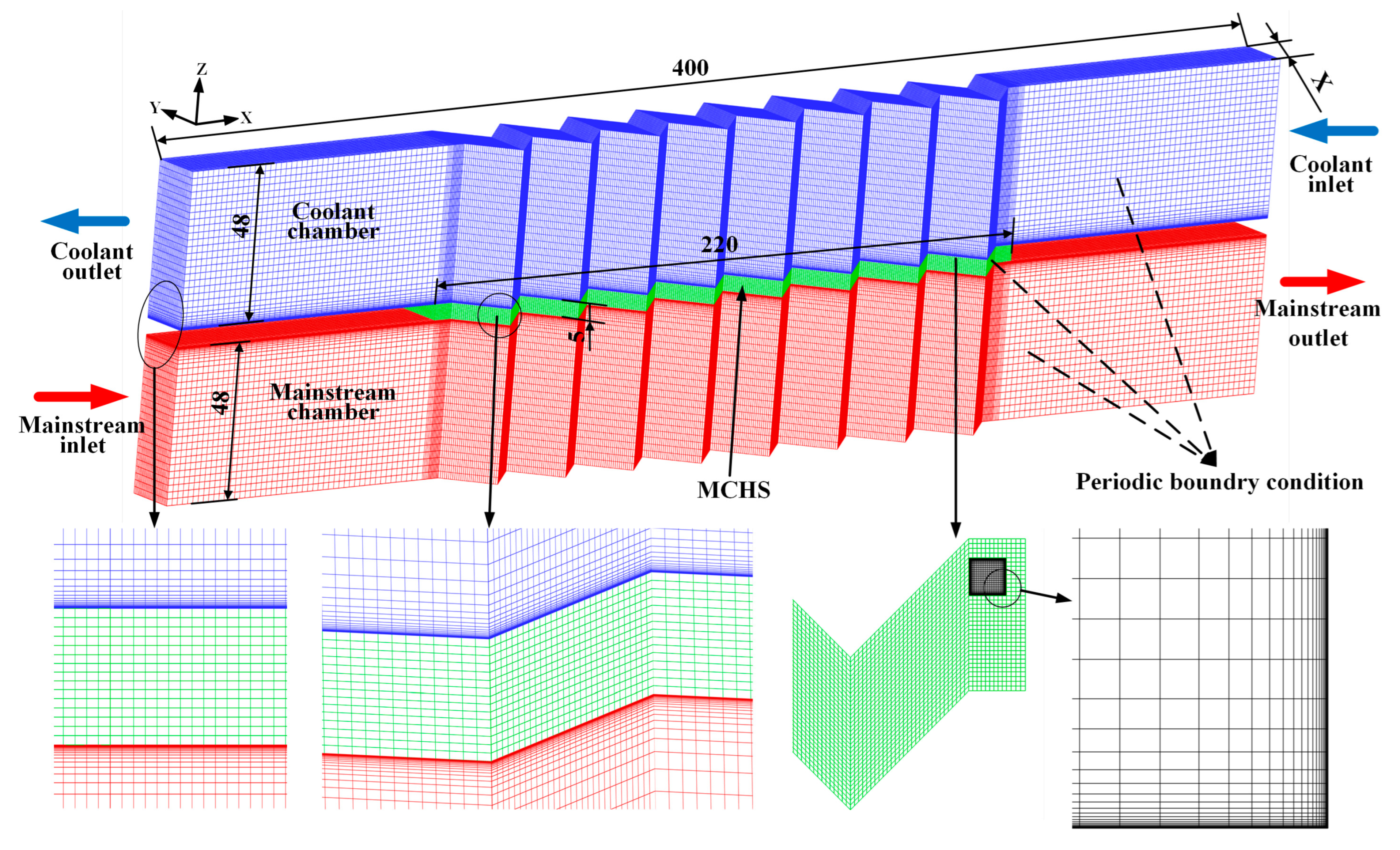
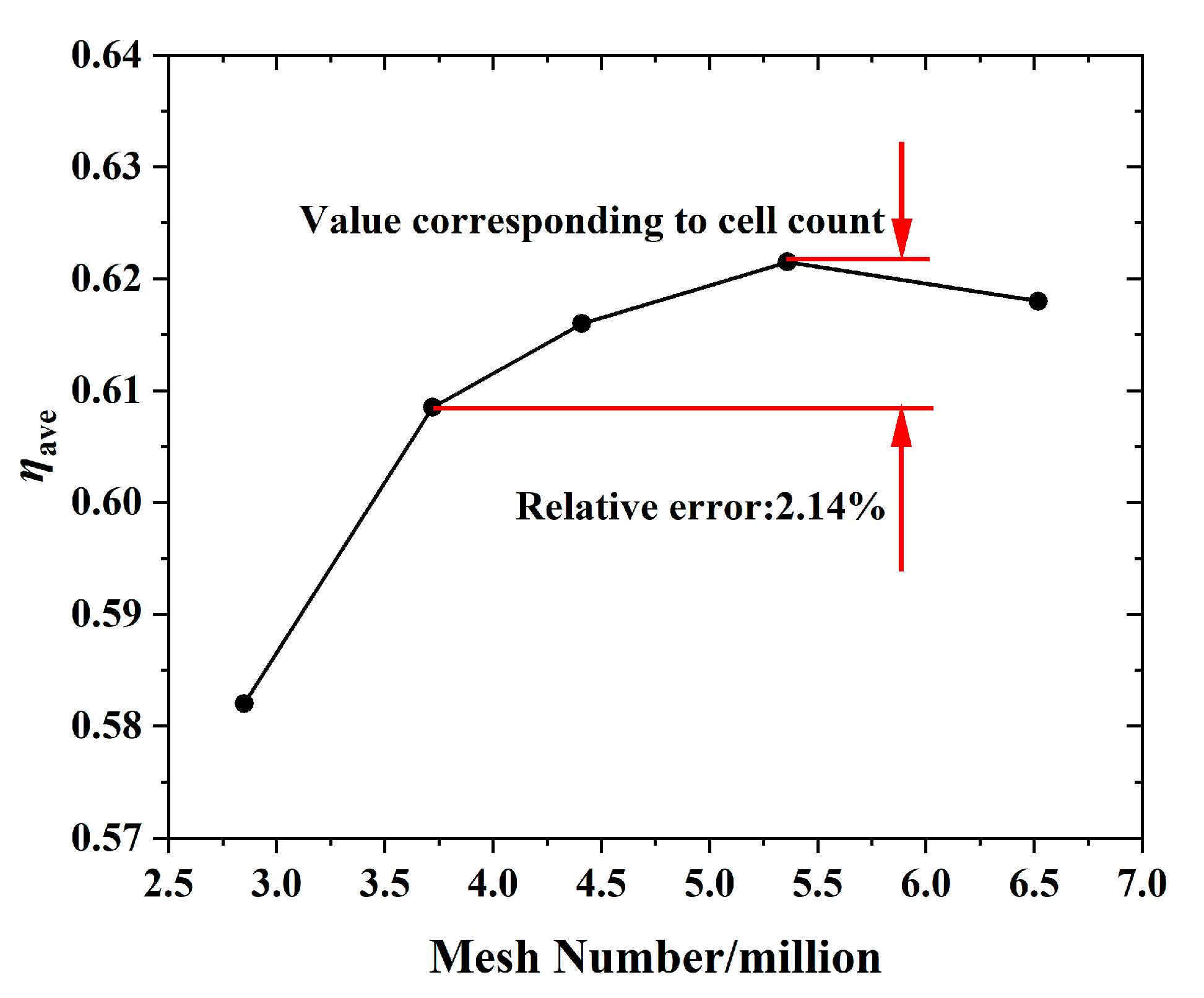
2.2. Brief Description of CFD Modeling

Figure 3 presents the overall view of the mesh. The computation domain consists of coolant chamber, mainstream chamber, double-staggered zigzag cooling channels, and a solid board. The length of the cooling channel was 200 mm, and the MCHS was 220 mm. To improve the stability of the airflow, the inlet and outflow were expanded by 100 mm, while the mainstream chamber and coolant were both 400 mm. The structured grids were generated using the software ICEM CFD 17.0. A local grid refinement was applied in the near-wall regions, and y+ of the first layer near the wall was less than 1. To achieve this requirement, the first layer’s mesh in close proximity to the wall was 0.0001 mm, with a grid growth rate of 1.2.
The reliability of the calculation is highly dependent on the selection of the turbulence model, and each turbulence model has its most suitable application situation. Therefore, choosing the right turbulence model for the zigzag MCHS is crucial. Singh et al. [26] has pointed out that the RNG k ε model has the best accuracy for simulating zigzag MCHS. In addition, according to our study of similar structures, we have found that the RNG k ε model is more suitable for the prediction of lamilloy cooling with internal channels [44,45]. Therefore, in this work, the RNG k ε model was utilized using the commercial program ANSYS CFX 17.0. The temperature and flow fields in the solid and fluid domains were solved using the 3D stable viscous Reynolds-averaged Navier–Stokes (RANS) equations. Heat transport in the interface was also calculated using the fluid-solid surface. The convective term, diffusion term, and source term were spatially discretized using the second-order difference technique. When all residuals were less than 10 5 , the solutions were said to have converged.
In the process of simulation calculation, the fluid medium is ideal gas, with a turbulence intensity of 5%, which is pressure and temperature dependent. The inlet speed of the coolant is 10 m/s with static temperature of 740.15 K; the outlet average static pressure of the coolant is 2.2885 MPa. The inlet speed of the mainstream is 72.76 m/s with static temperature of 1795 K; the outlet average static pressure of the mainstream is 2.1965 MPa. All the spanwise surfaces are assumed to be translationally periodic.
To obtain the convergence result quickly, the initial conditions are set as follows. Coolant chamber is 10 m/s with static temperature of 740.15 K and mainstream chamber is 72.76 m/s with static temperature of 1795 K, which are consistent with boundary conditions. The internal channels are 50 m/s with static temperature of 740.15 K, and the solid domain is 1000 K.
The sensitivity analysis of the results of numerical simulation were carried out, and there were five distinct cell counts employed, specifically 2.85 million, 3.72 million, 4.41 million, 5.36 million, and 6.52 million. Figure 4 presents the η a v e versus the mesh number; it demonstrates that starting with the second configuration, increasing the grids further did not significantly affect the solution, and the outcomes of such an arrangement are acceptable. All computations in this inquiry were performed on a computational cell with 4.41 million grids.

2.3. Brief Description of Optimization Flow Chart

Figure 5 illustrates the entire Kriging-based optimization process. The design space is established and five design variables are originally chosen.
Next, utilizing central composite design (CCD) as the design of experiment, the design points inside the design space are chosen. The coolant usage and total cooling efficacy are the values of the objective function. After constructing the Kriging model, NSGA-II searches for optimum spots.
Modeling approaches are necessary in order to generate an appropriate surrogate model. DoE often comes in a variety of forms, such as Latin hypercube design (LHD), complete factor design, partial factor design, and central composite design (CCD). The CCD approach expands the design space and obtains higher-order information, which has the advantages of simple design, less test times, and good predictability, and has been applied to solar cooling [47]; this method is used in this paper. Axial (or star) points and a two-level complete factor design are included in the CCD. The axial number and two-level complete factor number are both 2k in the case of k factors. The number of center points ( N c ) and the number of factors (k) determine the total number of experimental trials ( N e ). The total number of trials conducted in the experiment is stated as:
N e = 2 k + 2 k + N c ,
The following formula is used by CCD to connect star points to full factor points:
s t a r u p p e r = b a s e + ( u p p e r b a s e ) × α ,
s t a r l o w e r = b a s e ( b a s e l o w e r ) × α ,
where b a s e , l o w e r , u p p e r are the center point of zero level, the low-level point and the high-level point of the full factor design, respectively, and l o w e r < b a s e < u p p e r .
The α is the scale factor; when α < 1 , the s t a r is located inside the full factor design, when α > 1 ,   the star is located outside the full factor design, and when α = 1 , the star is located at the center of the full factor design surface.
In this article,   k = 1 ,   N c = 1 , α = 1 . Thus:
N e = 2 5 + 2 × 5 + 1 = 43 ,
Here, CCD is used at two levels with five parameters. Table 1 displays each variable’s placement.
Building the surrogate model, which lowers computing costs, comes next after completing the numerical analysis using the sample points identified by CCD. Various surrogate models, including the RSM, Kriging model, and radial basis function neural network (RBF) model, have been created and utilized in the optimization of electrical machinery. It is possible to substitute the CFD needed for the optimization implementation with these stand-in models. Using random variables, one statistical method to estimate the value at non-design sites is the Kriging method. Kriging models are most commonly represented by a constant term plus a departure.
y ˜ ( x ) = f x + Z x ,
The unknown function of interest, denoted as y ˜ ( x ) , is known as f ( x ) , and the deviation Z x represents the realization of a stochastic process with nonzero covariance, variance of σ 2 , and mean of zero [48]. In this model, f ( x ) can be thought of as a “global” approximation for the entire design space, while Z x   is added to create “localized” deviations so that the model can interpolate sampled data points.
Table 2 shows 43 numerical designs selected by the CCD and their corresponding η a v e and m c . The η a v e and m c are calculated by the respective CFD model, which are elaborated in Section 3.1.
Based on a few distinct samples, error analysis was carried out to guarantee the accuracy of the built model. Figure 6 (Response fit plots) shows actual versus predicted response values for each response. It is evident that every point lies on or near the diagonal line, which indicates the approximation model predicts well based on the error points. The average error of η a v e and m c are 0.39% and 6.75%, respectively (calculated according to the average value of P r e d i c a t e d   v a l u e A c t u a l   v a l u e / A c t u a l   v a l u e ).
Relative graphs in Figure 7 show the discrepancy between the actual and expected values for all error sample points for each response. The residual values are random and follow a discernible shape with increasing response values, which indicate residuals are ideal. Thus, the model has excellent accuracy, is suitable for further improvement, and yields trustworthy optimization results.
Upon building the Kriging surrogate model, the global Pareto front of optimum solutions is searched. The best answers are really a trade-off between these goals; they are technically non-inferior options, sometimes known as Pareto solutions. The multi-objectives optimization procedure is used to obtain the Pareto solutions.
K. Deb and S. Agrawal [49] devised the Non-dominated Sorting Genetic Algorithm (NSGA-II). For a geological search, NSGA-II has population Q and Pareto archive P . The number of people in population Q is the same as the number of people in archive P in NSGA-II, which is N .
When optimizing, ensuring sure that the quantity of “zigzag” in the zigzag microchannels is an integer, the values of zigzag are defined as restricted values, as shown in Table 3.

3. Results and Analysis

3.1. Optimization Results

Figure 8 shows the Pareto front of the ideal solution. Three common optimal design points are shown in this image as Opt-A, Opt-B, and Opt-C, which stand for the various alternatives for using TOPSIS to find the maximum η a v e , minimal m c , and ideal solution, respectively. The TOPSIS theory is predicated on the notion that the viable scheme of choice ought to be near the ideal solution while being distant from the negative ideal solution [50,51].
The optimized and numerical CFD results are displayed in Table 4. Both the projected value from optimization and the CFD values are provided for the optimization scenarios. In addition, the reference case (Ref) takes an intermediate value for each variable for comparison. Opt-A possesses the maximum η a v e , increased by 6.82%, 18.13%, and 3.95% compared with the Ref case, Opt-B, and Opt-C, respectively, according to the CFD predictions. Meanwhile, m c is the largest, increased by 1.41 times, 8.90 times, and 0.67 times, respectively. Opt-B possesses the minimum m c and yields a decrease of 9.58% in η a v e and a decrease of 75.6% in m c with respect to the Ref case. For the compromise of both objective functions, an optimal structure produces an increase of 2.76% in η a v e and an increase of 44.8% in m c with respect to the Ref case. Additionally, the error of CFD values and predicted value by optimization is small, indicating that the optimization process is accurate. The above results show that different structural parameters have a huge influence on m c , and can even change its magnitude.

3.2. Comparison of Different Optimization Results

Figure 9 presents the local η distribution of the hot surface on solid board under different optimization condition. Figure 9a is the reference case which is intermediate value for each variable. It can be seen that on the MCHS, the position corresponding to the channels has higher cooling effect, which indicates that staggered zigzag cooling channels is obvious for improving cooling effect. Compared with Figure 9a, the structure of Opt-A possesses the smaller W and bigger Z. It can be seen that Opt-A yields higher local η , as shown in Figure 9b, indicating that the optimized structural parameters can improve the cooling effect, especially in the region of 100   m m < x < 100   m m . For Figure 9c, the minimum m c , the structure of Opt-B possesses the bigger W and Z; this indicates that along the x direction, the local η decreases, and the phenomenon of high cooling effectiveness at the corresponding position of the internal channels disappears, which implies that the more zigzags, the less m c , and the worse the cooling effect.
Figure 10 presents the local velocity distribution at z = 0 section of staggered zigzag cooling channels. It can be seen that Figure 10b has the least amount of zigzag, the coolant flows along the zigzag channels, and the velocity amplitude in its section is the largest, that is, the coolant flow ( m c ) through the channels is the largest, so the cooling effect is the best. Figure 10c has the most amount of zigzag, and the flow rate in its section is the smallest. At the same time, because its spanwise width (W) is the largest, both of them lead to the lowest cooling efficiency.
To decide the uniformity of temperature distributions at hot surface on solid board under different optimization condition, the two-dimensional temperature gradient is used.
d T d X = T x 2 + T y 2 ,
Figure 11 presents the local temperature gradient at z = 0 section of staggered zigzag cooling channels. It can be seen that the temperature gradient of the four structures is larger at the inlet of the coolant. The temperature gradient corresponding to Opt-A is the largest, especially at the position of the coolant channels. Due to the strong heat transfer effect of the cooling flow, the local temperature gradient is larger. The temperature gradient of Opt-B is small in the whole flow path, indicating that the temperature uniformity of the structure is the best.

4. Conclusions

In this work, a multi-objective optimization method for a microchannel heat sink (MCHS) based on computational fluid dynamics is carried out. To be specific, using the central composite design (CCD) method, 43 groups of structural parameters were selected for numerical calculation. Kriging model was used to establish the corresponding relation between the input geometric parameters and the objective function. The NSGA-II was applied to optimize the geometric parameters to obtain the maximum cooling effect and minimum coolant consumption. Finally, TOPSIS was used to select a group of structural parameters to achieve a compromise between two objectives. The following are the list of particular conclusions:
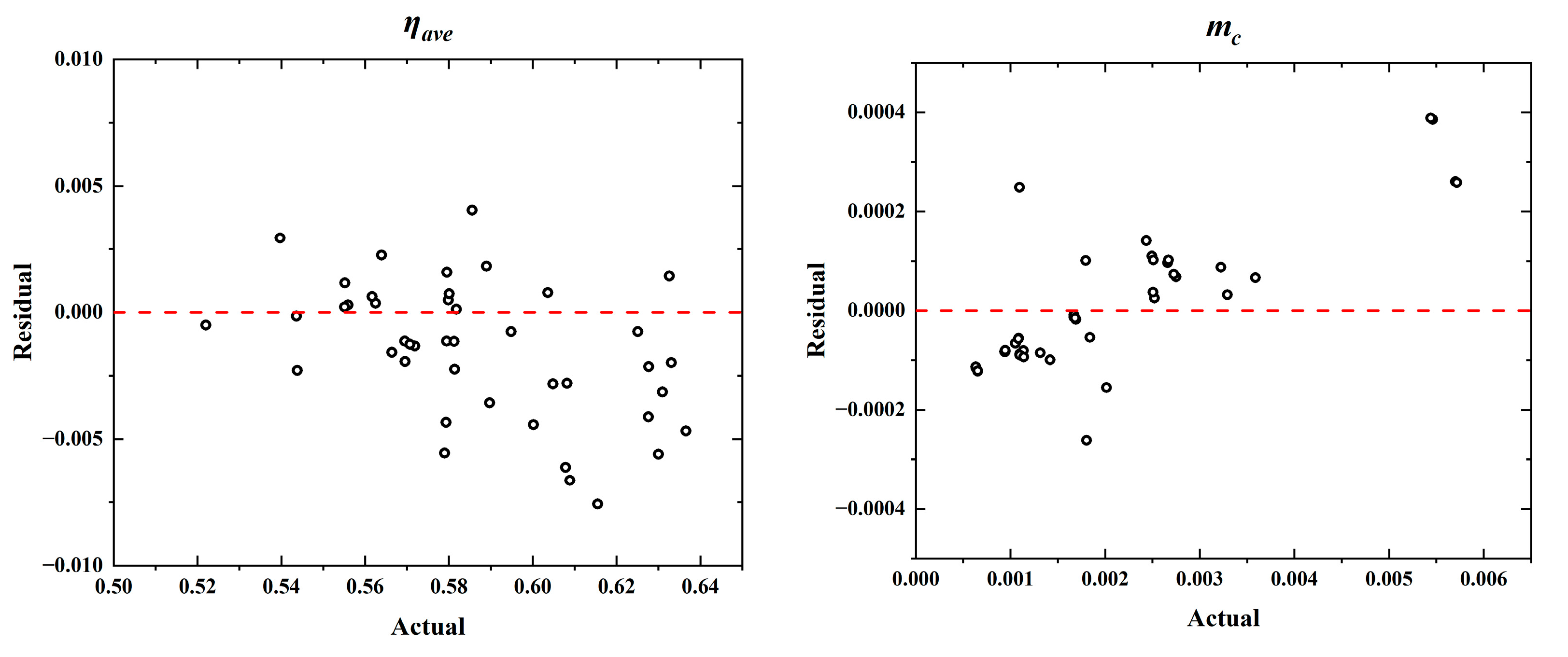
  • The established approximation model predicts well based on the error points; the average error of η a v e and m c are 0.39% and 6.75%, respectively.
  • The length of the “zigzag” (Z) and the periodic width (W) have a significant influence on the η a v e and m c ; to be specific, more zigzags and bigger periodic width obtain a worse cooling effect and consume less m c .
  • The error of CFD values and predicted value by optimization is small, and an optimal structure produces an increase of 2.76% in η a v e and an increase of 44.8% in m c with respect to Ref case.
  • The structure of Opt-A possesses a smaller W and bigger Z; it can be seen that Opt-A yields higher local η . The structure of Opt-B possesses a bigger W and Z; it can be seen that along the x direction, the cooling effectiveness decreases, and the phenomenon of high cooling effectiveness at the corresponding position of the internal channels disappears, which implies that the more zigzags, the less m c , and the worse the cooling effect.
  • Topology optimization can automatically generate free-form and efficient structures, and this numerical method has been introduced into the field of thermal fluid structure design in recent years. It is expected that the flow and heat transfer characteristics of the channels can be further improved by topological optimization.

Author Contributions

Conceptualization, X.Z. and T.Y.; methodology, X.Z.; software, T.Y.; validation, T.Y. and Z.C.; formal analysis, Z.C.; investigation, L.X. (Liang Xu); resources, X.Z.; data curation, T.Y.; writing—original draft preparation, T.Y.; writing—review and editing, J.G.; visualization, L.X. (Lei Xi); supervision, R.X.; project administration, P.Z.; funding acquisition, X.Z. All authors have read and agreed to the published version of the manuscript.

Funding

This research was funded by the National key research and development plan (2021YFF0602300).

Data Availability Statement

Data are contained within the article.

Conflicts of Interest

The authors declare no conflicts of interest.

References

  1. Tuckerman, D.B.; Pease, R.F. High-performance heat sinking for VLS. IEEE Electron Device Lett. 1981, 2, 126–129. [Google Scholar] [CrossRef]
  2. Naqiuddin, N.H.; Saw, L.H.; Yew, M.C.; Yusof, F.; Ng, T.C.; Yew, M.K. Overview of micro-channel design for high heat flux application. Renew. Sustain. Energy Rev. 2018, 82, 901–914. [Google Scholar] [CrossRef]
  3. Koç, M.; Mahabunphachai, S. Feasibility investigations on a novel micro-manufacturing process for fabrication of fuel cell bipolar plates: Internal pressure-assisted embossing of micro-channels with in-die mechanical bonding. J. Power Sources 2007, 172, 725–733. [Google Scholar] [CrossRef]
  4. Deng, Y.; Menon, S.; Lavrich, Z.; Wang, H.; Hagen, C.L. Design, simulation, and testing of a novel micro-channel heat exchanger for natural gas cooling in automotive applications. Appl. Therm. Eng. 2017, 110, 327–334. [Google Scholar] [CrossRef]
  5. Oyinlola, M.A.; Shire, G.S.F.; Moss, R.W. The significance of scaling effects in a solar absorber plate with micro-channels. Appl. Therm. Eng. 2015, 90, 499–508. [Google Scholar] [CrossRef]
  6. Moradikazerouni, A.; Afrand, M.; Alsarraf, J.; Mahian, O.; Wongwises, S.; Tran, M.-D. Comparison of the effect of five different entrance channel shapes of a micro-channel heat sink in forced convection with application to cooling a supercomputer circuit board. Appl. Therm. Eng. 2019, 150, 1078–1089. [Google Scholar] [CrossRef]
  7. Gunnasegaran, P.; Mohammed, H.A.; Shuaib, N.H.; Saidur, R. The effect of geometrical parameters on heat transfer characteristics of microchannels heat sink with different shapes. Int. Commun. Heat Mass Transf. 2010, 37, 1078–1086. [Google Scholar] [CrossRef]
  8. Khoshvaght-Aliabadi, M.; Rad, S.E.H.; Hormozi, F. Al2O3–water nanofluid inside wavy mini-channel with different cross-sections. J. Taiwan Inst. Chem. Eng. 2016, 58, 8–18. [Google Scholar] [CrossRef]
  9. Wang, H.; Chen, Z.; Gao, J. Influence of geometric parameters on flow and heat transfer performance of micro-channel heat sinks. Appl. Therm. Eng. 2016, 107, 870–879. [Google Scholar] [CrossRef]
  10. Chen, Y.; Zhang, C.; Shi, M.; Wu, J. Three-dimensional numerical simulation of heat and fluid flow in noncircular microchannel heat sinks. Int. Commun. Heat Mass Transf. 2009, 36, 917–920. [Google Scholar] [CrossRef]
  11. Chiu, H.-C.; Jang, J.-H.; Yeh, H.-W.; Wu, M.-S. The heat transfer characteristics of liquid cooling heatsink containing microchannels. Int. J. Heat Mass Transf. 2011, 54, 34–42. [Google Scholar] [CrossRef]
  12. Zhai, Y.L.; Xia, G.D.; Liu, X.F.; Li, Y.F. Exergy analysis and performance evaluation of flow and heat transfer in different micro heat sinks with complex structure. Int. J. Heat Mass Transf. 2015, 84, 293–303. [Google Scholar] [CrossRef]
  13. Adham, A.M.; Mohd-Ghazali, N.; Ahmad, R. Optimization of an ammonia-cooled rectangular microchannel heat sink using multi-objective non-dominated sorting genetic algorithm (NSGA2). Heat Mass Transf. 2012, 48, 1723–1733. [Google Scholar] [CrossRef]
  14. Halelfadl, S.; Adham, A.M.; Mohd-Ghazali, N.; Maré, T.; Estellé, P.; Ahmad, R. Optimization of thermal performances and pressure drop of rectangular microchannel heat sink using aqueous carbon nanotubes based nanofluid. Appl. Therm. Eng. 2014, 62, 492–499. [Google Scholar] [CrossRef]
  15. Gong, L.; Zhao, J.; Huang, S. Numerical study on layout of micro-channel heat sink for thermal management of electronic devices. Appl. Therm. Eng. 2015, 88, 480–490. [Google Scholar] [CrossRef]
  16. Vafai, K.; Zhu, L. Analysis of two layered micro!channel heat sink concept in electronic cooling. Int. J. Heat Mass Transf. 1999, 42, 2287–2297. [Google Scholar] [CrossRef]
  17. Cheng, Y.J. Numerical simulation of stacked microchannel heat sink with mixing-enhanced passive structure. Int. Commun. Heat Mass Transf. 2007, 34, 295–303. [Google Scholar] [CrossRef]
  18. Wong, K.-C.; Muezzin, F.N.A. Heat transfer of a parallel flow two-layered microchannel heat sink. Int. Commun. Heat Mass Transf. 2013, 49, 136–140. [Google Scholar] [CrossRef]
  19. Hung, T.-C.; Yan, W.-M.; Li, W.-P. Analysis of heat transfer characteristics of double-layered microchannel heat sink. Int. J. Heat Mass Transf. 2012, 55, 3090–3099. [Google Scholar] [CrossRef]
  20. Hung, T.-C.; Yan, W.-M.; Wang, X.-D.; Huang, Y.-X. Optimal design of geometric parameters of double-layered microchannel heat sinks. Int. J. Heat Mass Transf. 2012, 55, 3262–3272. [Google Scholar] [CrossRef]
  21. Wu, J.M.; Zhao, J.Y.; Tseng, K.J. Parametric study on the performance of double-layered microchannels heat sink. Energy Convers. Manag. 2014, 80, 550–560. [Google Scholar] [CrossRef]
  22. Al-Bakhit, H.; Fakheri, A. Numerical simulation of heat transfer in simultaneously developing flows in parallel rectangular ducts. Appl. Therm. Eng. 2006, 26, 596–603. [Google Scholar] [CrossRef]
  23. Sui, Y.; Teo, C.J.; Lee, P.S.; Chew, Y.T.; Shu, C. Fluid flow and heat transfer in wavy microchannels. Int. J. Heat Mass Transf. 2010, 53, 2760–2772. [Google Scholar] [CrossRef]
  24. Chamanroy, Z.; Khoshvaght-Aliabadi, M. Analysis of straight and wavy miniature heat sinks equipped with straight and wavy pin-fins. Int. J. Therm. Sci. 2019, 146, 106071. [Google Scholar] [CrossRef]
  25. Brodnianská, Z.; Kotšmíd, S. Intensification of convective heat transfer in new shaped wavy channel configurations. Int. J. Therm. Sci. 2021, 162, 106794. [Google Scholar] [CrossRef]
  26. Singh, S.; Singh, A.; Chander, S. Thermal performance of a fully developed serpentine wavy channel solar air heater. J. Energy Storage 2019, 25, 100896. [Google Scholar] [CrossRef]
  27. Chiam, Z.L.; Lee, P.S.; Singh, P.K.; Mou, N. Investigation of fluid flow and heat transfer in wavy micro-channels with alternating secondary branches. Int. J. Heat Mass Transf. 2016, 101, 1316–1330. [Google Scholar] [CrossRef]
  28. Mohammed, H.A.; Gunnasegaran, P.; Shuaib, N.H. Numerical simulation of heat transfer enhancement in wavy microchannel heat sink. Int. Commun. Heat Mass Transf. 2011, 38, 63–68. [Google Scholar] [CrossRef]
  29. Sakanova, A.; Keian, C.C.; Zhao, J. Performance improvements of microchannel heat sink using wavy channel and nanofluids. Int. J. Heat Mass Transf. 2015, 89, 59–74. [Google Scholar] [CrossRef]
  30. Mohammed, H.A.; Gunnasegaran, P.; Shuaib, N.H. Influence of channel shape on the thermal and hydraulic performance of microchannel heat sink. Int. Commun. Heat Mass Transf. 2011, 38, 474–480. [Google Scholar] [CrossRef]
  31. Duangthongsuk, W.; Wongwises, S. An experimental investigation on the heat transfer and pressure drop characteristics of nanofluid flowing in microchannel heat sink with multiple zigzag flow channel structures. Exp. Therm Fluid Sci. 2017, 87, 30–39. [Google Scholar] [CrossRef]
  32. Ma, D.D.; Xia, G.D.; Li, Y.F.; Jia, Y.T.; Wang, J. Effects of structural parameters on fluid flow and heat transfer characteristics in microchannel with offset zigzag grooves in sidewall. Int. J. Heat Mass Transf. 2016, 101, 427–435. [Google Scholar] [CrossRef]
  33. Ma, D.D.; Xia, G.D.; Wang, J.; Yang, Y.C.; Jia, Y.T.; Zong, L.X. An experimental study on hydrothermal performance of microchannel heat sinks with 4-ports and offset zigzag channels. Energy Convers. Manag. 2017, 152, 157–165. [Google Scholar] [CrossRef]
  34. Dai, Z.; Zheng, Z.; Fletcher, D.F.; Haynes, B.S. Experimental study of transient behaviour of laminar flow in zigzag semi-circular microchannels. Exp. Therm Fluid Sci. 2015, 68, 644–651. [Google Scholar] [CrossRef]
  35. Ren, Y.; Leung, W.W.-F. Flow and mixing in rotating zigzag microchannel. Chem. Eng. J. 2013, 215–216, 561–578. [Google Scholar] [CrossRef]
  36. Peng, Y.; Li, Z.; Li, S.; Cao, B.; Wu, X.; Zhao, X. The experimental study of the heat ransfer performance of a zigzag-serpentine microchannel heat sink. Int. J. Therm. Sci. 2021, 163, 106831. [Google Scholar] [CrossRef]
  37. Nemati, H.; Moghimi, M.A.; Meyer, J.P. Shape optimisation of wavy mini-channel heat sink. Int. Commun. Heat Mass Transf. 2021, 122, 105172. [Google Scholar] [CrossRef]
  38. Lampio, K.; Karvinen, R. Optimization of convectively cooled heat sinks. Microelectron. Reliab. 2017, 79, 473–479. [Google Scholar] [CrossRef]
  39. Leng, C.; Wang, X.-D.; Wang, T.-H.; Yan, W.-M. Optimization of thermal resistance and bottom wall temperature uniformity for double-layered microchannel heat sink. Energy Convers. Manag. 2015, 93, 141–150. [Google Scholar] [CrossRef]
  40. Sakanova, A.; Yin, S.; Zhao, J.; Wu, J.M.; Leong, K.C. Optimization and comparison of double-layer and double-side micro-channel heat sinks with nanofluid for power electronics cooling. Appl. Therm. Eng. 2014, 65, 124–134. [Google Scholar] [CrossRef]
  41. Chen, X.; Li, T. A novel passive micromixer designed by applying an optimization algorithm to the zigzag microchannel. Chem. Eng. J. 2017, 313, 1406–1414. [Google Scholar] [CrossRef]
  42. Rostami, J.; Abbassi, A.; Saffar-Avval, M. Optimization of conjugate heat transfer in wavy walls microchannels. Appl. Therm. Eng. 2015, 82, 318–328. [Google Scholar] [CrossRef]
  43. Normah, G.-M.; Oh, J.-T.; Chien, N.B.; Choi, K.-I.; Robiah, A. Comparison of the optimized thermal performance of square and circular ammonia-cooled microchannel heat sink with genetic algorithm. Energy Convers. Manag. 2015, 102, 59–65. [Google Scholar] [CrossRef]
  44. Yang, T.; Sun, Y.; Xu, L.; Yang, X.; Duan, D.; Xi, L.; Gao, J.; Li, Y. Flow and heat transfer characteristics in cooling lamilloy with internal MCs. Int. J. Heat Mass Transf. 2023, 201, 123645. [Google Scholar] [CrossRef]
  45. Yang, T.; Zhang, X.; Chang, Z.; Xu, L.; Xi, L.; Gao, J.; Kou, W.; Jing, X. Study on Flow and Heat Transfer Characteristics in Lamilloy Structure with Different Configurations of Internal Minichannels. Energies 2023, 16, 8058. [Google Scholar] [CrossRef]
  46. Lee, K.-D.; Kim, K.-Y. Surrogate based optimization of a laidback fan-shaped hole for film-cooling. Int. J. Heat Fluid Flow 2011, 32, 226–238. [Google Scholar] [CrossRef]
  47. Hang, Y.; Qu, M.; Ukkusuri, S. Optimizing the design of a solar cooling system using central composite design techniques. Energy Build. 2011, 43, 988–994. [Google Scholar] [CrossRef]
  48. Kleijnen, J.P.C. Kriging metamodeling in simulation: A review. Eur. J. Oper. Res. 2009, 192, 707–716. [Google Scholar] [CrossRef]
  49. Deb, K.; Pratap, A.; Agarwal, S.; Meyarivan, T. A fast and elitist multi-objective genetic algorithm. IEEE Trans. Evol. Comput. 2002, 6, 182–197. [Google Scholar] [CrossRef]
  50. Ahmadi, A.; Moghimi, H.; Nezhad, A.E.; Agelidis, V.G.; Sharaf, A.M. Multi-objective economic emission dispatch considering combined heat and power by normal boundary intersection method. Electr. Power Syst. Res. 2015, 129, 32–43. [Google Scholar] [CrossRef]
  51. Ge, Y.; Liu, Z.; Liu, W. Multi-objective genetic optimization of the heat transfer for tube inserted with porous media. Int. J. Heat Mass Transf. 2016, 101, 981–987. [Google Scholar] [CrossRef]
Figure 1. Diagram of gas turbine combustor.
Energies 17 00818 g001
Figure 2. Three-dimensional geometry of the MCHS with internal channels.
Energies 17 00818 g002
Figure 3. Mesh of numerical calculation.
Energies 17 00818 g003
Figure 4. Grid independence calculation.
Energies 17 00818 g004
Figure 5. Optimization procedure using kriging method [46].
Energies 17 00818 g005
Figure 6. Response fit plots for η a v e and m c .
Energies 17 00818 g006
Figure 7. Residual plots for η a v e and m c .
Energies 17 00818 g007
Figure 8. Pareto front and the optimum solution selected by TOPSIS.
Energies 17 00818 g008
Figure 9. Comparisons of local η . (a) Ref case, (b) maximum η a v e (Opt-A), (c) minimum m c (Opt-B), (d) compromise between both objectives (Opt-C).
Energies 17 00818 g009
Figure 10. Comparisons of local velocity. (a) Ref case, (b) maximum η a v e (Opt-A), (c) minimum m c (Opt-B), (d) compromise between both objectives (Opt-C).
Energies 17 00818 g010
Figure 11. Comparisons of the temperature gradient. (a) Ref case, (b) maximum η a v e (Opt-A), (c) minimum m c (Opt-B), (d) compromise between both objectives (Opt-C).
Energies 17 00818 g011
Table 1. Optimizing levels and related factors.
ParametersLower BoundCentral PointUpper Bound
A246
B246
W141618
H11.21.62
Z512.520
Table 2. Training and testing samples.
ABW H 1 Z η a v e m c
44161.612.50.615530.00250
2214250.581790.00106
22182200.589750.00180
26141.250.543610.00094
6218250.570710.00110
22141.2200.579440.00109
62142200.579020.00110
6614250.543810.00169
66181.250.539750.00094
62141.250.561710.00066
26181.2200.604850.00266
26142200.636610.00546
2618250.580080.00167
66141.2200.579310.00275
66182200.627640.00570
62181.2200.569540.00114
22181.250.555920.00064
42161.612.50.581260.00132
4416212.50.633050.00329
44161.6200.627670.00322
64161.612.50.600160.00251
44161.650.585570.00142
46161.612.50.632620.00359
44161.212.50.594870.00184
44141.612.50.625070.00252
24161.612.50.607840.00244
44181.612.50.608900.00251
6214250.579860.00110
66142200.630980.00572
22142200.603580.00180
26181.250.555150.00094
62141.2200.579550.00114
2218250.571890.00105
2614250.566400.00167
66181.2200.581390.00273
62182200.588940.00202
26141.2200.608210.00267
6618250.563920.00168
22141.250.562510.00063
62181.250.555130.00065
66141.250.521980.00094
26182200.630010.00544
22181.2200.569510.00109
Table 3. The restricted values for N.
N567891011121314151617181920
Z20.016.6714.2912.511.1110.09.098.337.697.146.676.255.885.565.265.0
Table 4. Comparison of reference and optimized results.
Design Variables η a v e m c (kg/s)
ABW H 1 ZCFDNSGA-IICFDNSGA-II
Refmedian44161.612.50.6160.00250
Opt-A Maximum   η a v e 3.765.2314.511.9116.670.6580.6640.006040.00552
Opt-B Minimum   m c 3.092.4016.251.315.260.5570.5640.000610.00040
Opt-Ccompromise2.724.5114.491.5514.290.6330.6360.003620.00320
Disclaimer/Publisher’s Note: The statements, opinions and data contained in all publications are solely those of the individual author(s) and contributor(s) and not of MDPI and/or the editor(s). MDPI and/or the editor(s) disclaim responsibility for any injury to people or property resulting from any ideas, methods, instructions or products referred to in the content.

