Article

Optimization of Blades and Impellers for Electric Vehicle Centrifugal Pumps via Numerical Analysis

1
Department of Mechanical Engineering, Graduate School of Kongju National University, 1223-24, Cheonan-daero, Seobuk-gu, Cheonan-si 31080, Republic of Korea
2
Department of Future Convergence Engineering, Kongju National University, 1223-24, Cheonan-daero, Seobuk-gu, Cheonan-si 31080, Republic of Korea
3
Coavis, Inc., Sejong-si 30058, Republic of Korea
4
Department of Future Automotive Engineering, Kongju National University, 1223-24, Cheonan-daero, Seobuk-gu, Cheonan-si 31080, Republic of Korea
5
Institute of Green Car Technology, Kongju National University, 1223-24, Cheonan-daero, Seobuk-gu, Cheonan-si 31080, Republic of Korea
*
Author to whom correspondence should be addressed.
Energies 2024, 17(4), 853; https://doi.org/10.3390/en17040853
Submission received: 21 December 2023 / Revised: 16 January 2024 / Accepted: 7 February 2024 / Published: 11 February 2024
(This article belongs to the Section E: Electric Vehicles)

Abstract

:
Since the 2015 Paris Agreement, efforts for environmental protection have gained prominence worldwide. Accordingly, electric vehicles have become increasingly relevant. Thus, improving the performance of the water pump, a key component of cooling systems in electric vehicles, is crucial. Electric vehicles operate on batteries and motors, making their cooling systems remarkably complex. Efficient operation of the water pump is directly related to the stable performance of electric vehicles and is therefore critical. This study conducted numerical analyses using Ansys Fluent to evaluate water pump performance by varying key parameters, namely, number of blades and outer diameter of the impeller. When the number of blades was changed to 7, 9, 11, and 13, the efficiency, head, and thrust tended to increase. In particular, for blade counts greater than 11, the fluid flow was found to stabilize with negligible effect on pump performance. When the outer diameter of the impeller was 70, 69, 68, and 67 mm, although efficiency decreased, the head and thrust tended to increase. Based on these comprehensive results, a structure was proposed for the shape of the optimized water pump. The development of efficient and stable water pumps is expected to contribute to the performance improvement of electric vehicles.

1. Introduction

1.1. Research Background

The Paris Agreement in 2015 has led to a global surge in efforts aimed at alleviating global warming via reducing greenhouse gas emissions and achieving carbon neutrality [1]. These efforts have focused on automobiles and cargo transportation that use fossil fuels, which are major sources of CO2. Accordingly, Europe and the United States are planning to promote the distribution of eco-friendly automobiles and reduce the use of internal combustion engine vehicles from 2023 [2]. In this rapidly evolving scenario, the development of eco-friendly vehicles and their components has been actively underway [3,4].
Eco-friendly vehicles, such as hybrid electric vehicles (HVEs), electric vehicles (EVs), and fuel cell electric vehicles (FCEVs), use batteries for energy storage and, unlike internal combustion engines, electric motors as driving units. In EVs, temperature management of the battery and cabin according to the surrounding environment is considered an important task [5,6]. Therefore, cooling systems are crucial for optimizing battery efficiency and preventing damage and thermal runaway due to high temperatures [7]. The cooling system maintains an appropriate temperature by dissipating the heat generated by the battery and drive motor to the external environment. Cooling systems are becoming increasingly complex as a result of technological advancements, such as increased battery capacity and improved drive motor output. Therefore, the cooling systems of EVs require greater amounts of coolant, and high-performance water pumps must be developed [8,9].
Centrifugal water pumps are primarily used in EVs. They utilize pressure differences to circulate the coolant effectively and have the advantages of high efficiency and low noise [10,11]. Improving the pump efficiency is an important goal in the field of pump technology, and the energy consumption of pumps accounts for a large proportion of EV systems [12,13]. Therefore, reduction in energy consumption by improving the pump efficiency has been actively researched [14].
Centrifugal pumps use power to rotate the impeller and supply energy to the fluids. This energy is converted into pressure energy through a volute casing. Through this process, the fluid transfers energy from the suction part to the discharge; as a result, phenomena such as three-dimensional abnormal turbulent flow, eddy currents, and flow separation occur in the fluid within the pump, making it difficult to predict the factors causing performance degradation [15,16]. With the current advances in computational power and computational fluid dynamics (CFD), effective analyses of the internal flow of electric water pumps have been performed so as to achieve improved performances and efficiencies [17,18,19,20].

1.2. Literature Review

The performance and efficiency of EV water pumps are significantly affected by several key factors and operating conditions. In particular, the shapes of the impeller and volute casing directly affect the pump performance. Moreover, various design variables, such as the number of blades, blade wrap angle, blade thickness, and blade outlet angle, have a significant impact on the pump performance; therefore, many studies have focused on these aspects. Tan et al. [21] investigated the effect of variations in the wrap angle of an impeller blade on the pump performance. They determined the effect of the blade wrap angle on the pump head and efficiency and also observed that increasingly stable pressure gradients were formed as the blade wrap angle increased. Additionally, they concluded that the highest head and efficiency occurred at the largest angle. Xu et al. [22] investigated the effects of blade thickness on the flow and performance of centrifugal pumps. They reported that, as the blade thickness increased, the pressure fluctuation at the impeller outlet increased. Further, as the blade thickness increased, the pump head decreased and the best efficiency point (BEP) occurred in the low-flow range. Peng et al. [23] investigated the performance of a centrifugal pump with five different impeller blade exit angles through a comparative analysis of simulation and experimental results. The results confirmed that the head and shaft power of the pump increased as the impeller blade outlet angle increased. However, the efficiency decreased and the performance of the pump deteriorated as the outlet angle increased. Abo Elyamin et al. [24] investigated the effect of the number of impeller blades on the performance of centrifugal pumps via Ansys Fluent simulations. They applied the renormalization group (RNG) k ε model for turbulence modeling and analyzed the flow field for three cases with blade numbers of five, seven, and nine. Consequently, the case with seven blades was found to be superior. Houlin et al. [25] investigated the effect of the number of blades in a centrifugal pump on the flow field. Their study employed a model pump with a design specific speed of 92.7 and five blades, and the number of blades was then changed to four, six, and seven. Through Fluent simulations, they demonstrated that the number of blades has a significant effect on the low-pressure area behind the blade inlet and the head tends to increase with the number of blades. Jafarzadeh et al. [26] studied the effects of the number of impeller blades on the efficiency of centrifugal pumps. Using commercial CFD, they analyzed the flow field when the numbers of blades were five, six, and seven by using three different turbulence models, the standard k ε model, RNG model, and Reynolds stress model (RSM). The best results were obtained for the scenario wherein the number of blades was seven. Shojaeefard et al. [27] evaluated the performance of centrifugal pumps by using a three-dimensional flow simulation. To analyze the pump performance, some geometric characteristics, such as the outlet angle and impeller passage width, were changed and consistent numerical and experimental results were obtained. It was demonstrated that the pump head and efficiency were improved because of the modified outlet angle and passage width.
Most previous studies analyzed the performance according to various shape design variables with the goal of improving the efficiency of industrial pumps and demonstrated their applicability in industrial fields. However, in light of the recently increased interest in EVs, more extensive research on high-performance, high-efficiency, and compact EV water pumps is warranted.

1.3. Motivation and Novelty

The modern automobile industry emphasizes eco-friendliness and efficiency; thus, improving the performance of each vehicle component is essential. In particular, the cooling system is considered an important factor that significantly affects the motor performance, battery efficiency, and lifespan of a vehicle. This study focused on improving the performance and efficiency of EV water pumps.
Water pumps are important components of vehicle cooling systems; however, the current pump design and performance still have potential for improvement. Therefore, this study focused on centrifugal pumps for EVs and entailed an analysis of the impact of changes in design variables, namely, the number of blades and impeller outer diameter, on the pump performance and efficiency. Notably, improving the efficiency by even 1% can reduce the overall system energy consumption of EVs and increase the driving range.
Unlike industrial centrifugal pumps, those for EVs require unique characteristics, such as small size, light weight, high efficiency, low power consumption, stable performance at high and low temperatures, and minimal noise and vibration. Therefore, in this study, we aimed to derive the characteristics suitable for centrifugal pumps in EVs and contribute to improving the performance of EVs through the design and verification of a compact yet highly efficient and high-output pump.
The remainder of this paper is organized as follows. Section 2 details the simulation of a water pump for EVs. Section 3 presents the verification of the experimental and simulation results and a discussion on the results of a comparative analysis of the performance and efficiency of the pump with respect to the number of blades and impeller outer diameter.

2. Computational Models and Verification

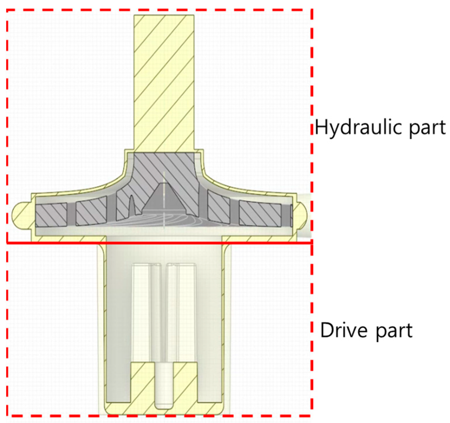
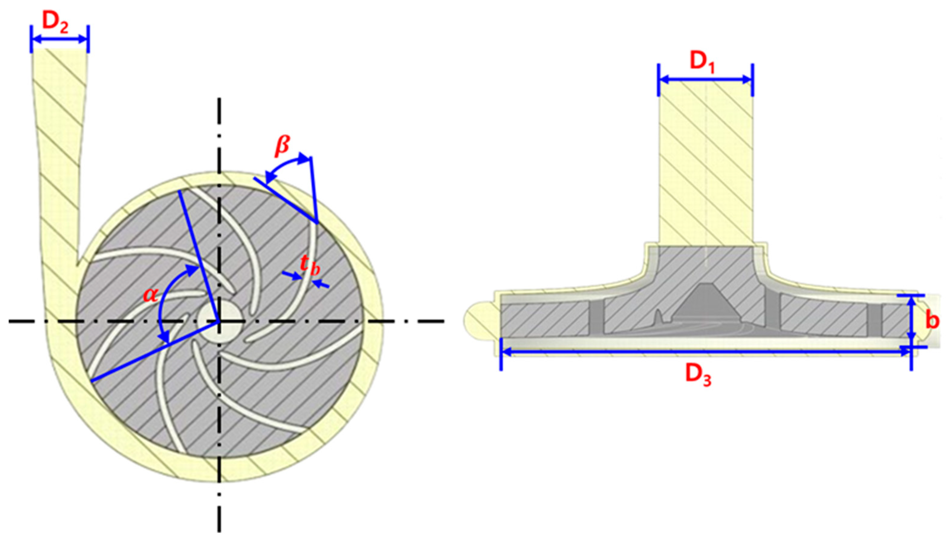
2.1. Water Pump Geometry

In this study, an analysis model based on a 104 W EV water pump was designed. The water pump comprises a drive and hydraulic part. The drive part refers to the motor that drives the pump, and the hydraulic part sucks fluid and delivers it to the discharge. This structure is illustrated in Figure 1. To facilitate smooth analysis during the modeling process, the water pump was divided into inlet and impeller volute casing. Unnecessary parts were omitted to simplify the model shape. Additionally, considering the backflow phenomenon caused by the strong wake flow occurring at the pump outlet, the inlet and outlet diameters were increased by 5 and 10 times, respectively [28]. Detailed information about this model is provided in Figure 2 and Figure 3 and Table 1.

2.2. Numerical Analysis

To analyze the impact of the changes in the water pump shape on the performance and efficiency, finite volume method (FVM)-based CFD simulations were performed using the commercial program Ansys Fluent 2022 R1. Numerical analyses were performed to accurately determine the fluid flow and pressure distribution. FVM entails subdividing the computational domain into a finite number of volumes and discretizing the governing equations, which are integral equations, and solving them via a matrix method to model the flow behavior.
Problems that do not satisfy various conservation laws often occur when discretizing differential equations. However, because the FVM involves the discretization of integral equations, it is possible to obtain a discretized set of equations that satisfies these laws by considering the conservation of mass, momentum, and energy in microscopic regions.
Numerical analyses involve converting nonlinear partial differential equations, such as the Navier–Stokes equations, into algebraic equations by using numerical techniques to discretize the flow domain.

2.2.1. Governing Equation

In numerical analysis, equations representing the conservation of mass, momentum, and energy are key, as they are used to describe the relevant physical phenomena. These basic equations are also applicable to incompressible fluids and three-dimensional unsteady flows. In Cartesian co-ordinates, the continuity equation and momentum conservation equation can be expressed as Equations (1) and (2), respectively.
ρ t + x i ρ u i = 0
t ρ u i + x i ρ u i u j = P x i + τ i j x i + ρ g i + F i
Here, ρ represents the fluid density, t represents the time, u i represents the velocity component, P represents the static pressure, and τ i j represents the stress tensor. ρ g i and F i represent the volume force due to gravity and external force, respectively. The stress tensor τ i j can be expressed as:
τ i j = u u i x j + u j x i 2 3 u u k x k i j
The second term on the right-hand side represents the volume expansion effect.

2.2.2. Turbulent Model

An efficient turbulence model must be used to solve the Navier–Stokes equations. The standard k ε model and the standard k ω model are commonly used. The k ε model is mainly used to analyze areas away from the flow boundary, and the k ω model is mainly suitable for analyzing areas near the boundary. The shear stress transport (SST) k ω turbulence model, which combines the advantages of the two aforementioned turbulence models, provides accurate predictions in flows involving flow separation. Accordingly, in this study, the SST k ω model was deemed suitable for numerical analyses of centrifugal pumps. The equations of the SST k ω model can be expressed as Equations (4)–(6).
t ρ k + x i ρ k u i = x j Γ k k x j + G ~ k Y k + S k
Γ k = μ + μ t σ k
Γ ω = μ + μ t σ ω
Here, k represents turbulence kinetic energy and ω represents specific dissipation rate. G ~ k represents the generation of turbulent kinetic energy due to the average velocity gradient and G ω represents the generation of the specific extinction rate ω . Y k and Y ω denote dissipation by turbulence for k and ω , respectively. Additionally, D k represents the cross-diffusion condition, and S k and S ω represent user-defined generation terms.

2.3. Grid Generation and Dependency Verification

In this study, grid creation was performed using the meshing function in Ansys 2022 R1. Because grid generation has a significant impact on the analysis convergence and flow patterns, appropriate grid selection is critical. Commonly used grids can be classified into structured and unstructured grids. Structured grids structurally partition the flow domain to form an efficient grid in the desired region and afford the advantage of fast convergence. However, the application of these grids may be difficult in the case of complex geometries. In contrast, unstructured grids can be applied in the case of complex shapes relatively easily but have the drawback of relatively slow convergence speeds.
Therefore, in this study, considering the complex flow regime of the water pump, an unstructured grid was selected for accurate analyses, in spite of the relatively slow convergence speed. Grid selection is based on the complexity of the flow domain and difficulty in applying a structured grid. Figure 4 shows the grid creation process applied in this study. Evidently, inflation was applied to account for the viscous effect on the wall, and the grid around the wall was densely constructed. In addition, in complex flow spaces, the grid cells were densely arranged using proximity-based sizing. In particular, for shapes such as volute casings, curvature control was applied to capture the curvature to ensure accurate results.
As the number of grids directly affects the analysis time, an optimal grid size was applied to effectively reduce the analysis time in a simple flow space.
Increasing the grid density can improve the convergence and accuracy of the analysis model. However, higher-density grids require longer calculation times. Therefore, in this study, we performed tests to evaluate the grid dependence. The influence of the grid number on the pump head, which was selected as the key variable in the study, was investigated.
As shown in Figure 5, the pump head tends to increase with the number of grid cells. However, in the case of approximately 5.8 million grid cells, the pump head was found to be 13.64 m; when the number of grid cells was further increased to approximately 7.6 million, the pump head was 13.68 m, a difference of approximately 0.3%. Thus, selecting the optimal number of grid cells, considering the balance between the analysis accuracy and computation time, is necessary. A grid with approximately 5.8 million cells was selected for the analyses in this study.

2.4. Boundary Conditions

In this study, the water pump performance characteristics of electric vehicles were analyzed. Because electric vehicle water pumps are compact and have unique characteristics, it is important to understand performance changes depending on the pump shape. Therefore, the pump characteristics were examined by applying various shape variations. The analysis was performed under steady-state conditions and the number of blades and impeller outer diameter were set as main variables. The number of blades was changed to 7, 9, 11, and 13, the impeller outer diameter was changed to 67 mm, 68 mm, 69 mm, and 70 mm, and the effect on pump performance was investigated. In addition, considering the mold manufacturing aspect, the range of shape variation was appropriately set. Additionally, the study sought to observe the performance changes due to shape variations at an impeller rotational speed of 3800 RPM and a flow rate of 14 LPM. Based on the experimental results, the inlet was set as a pressure boundary condition, the outlet as a mass flow rate condition, and the turbulence intensity at the inlet and outlet was set to 5% to account for potential backflow. The coolant used in this study was a mixture of water and ethylene glycol in a 1:1 ratio and its properties are listed in Table 2.
This is because flow-analysis programs generally do not consider the rotational influence of the pump impeller. To reflect the influence on the rotation of the pump impeller, additional models, such as the multiple reference frame (MRF), mixing plane model (MPM), and sliding mesh model (SMM), were applied. The MRF and MPM are mainly used for steady-state rotational analysis, whereas the SMM is mainly used for abnormal-state analysis. Therefore, in this study, the MRF model, which is primarily used for the analysis of rotating bodies in the steady state, was applied. The boundary conditions used in this study are listed in Table 3.
A coupled algorithm was used to solve the discretized equations. This algorithm effectively calculates pressure and momentum by processing the gradient terms of pressure and velocity through repeated calculations (Equation (2)). To minimize the diffusion term error of the turbulence model, the node-based Green–Gaussian method, which is preferred when applying turbulence modeling in a finite-volume-based numerical analysis, was employed to obtain accurate solutions.
Calculations of the pressure term (Equation (2)) were performed using the PRESTO! method. In particular, an accurate solution for a stable and effective pressure distribution can be obtained under complex conditions, such as the rapid pressure drops that occur during pump operation or flow areas with large curvatures, such as volute casings. Further, in the rotation and eddy flow analyses, quadratic upwind interpolation for convective kinematics (QUICK) was used to accurately compute various variables, such as momentum turbulence and kinetic energy. The QUICK method is effectively applied to fluid areas with complex geometries, such as rotating bodies, and yields accurate solutions under rapidly changing flow conditions.
Analysis convergence is established when the continuity residual reaches 10−3 and the turbulent kinetic energy and loss rate reach 10−6. In this study, the convergence standard value was set at 10−3. In addition, although the flow rates at the inlet and outlet should theoretically be the same, some errors may have occurred because of the nature of the numerical analysis. This error is generally considered to indicate convergence if it is less than 1% [29].
Using the aforementioned analysis process, the flow phenomena corresponding to various operating conditions were accurately modeled.

3. Results and Discussion

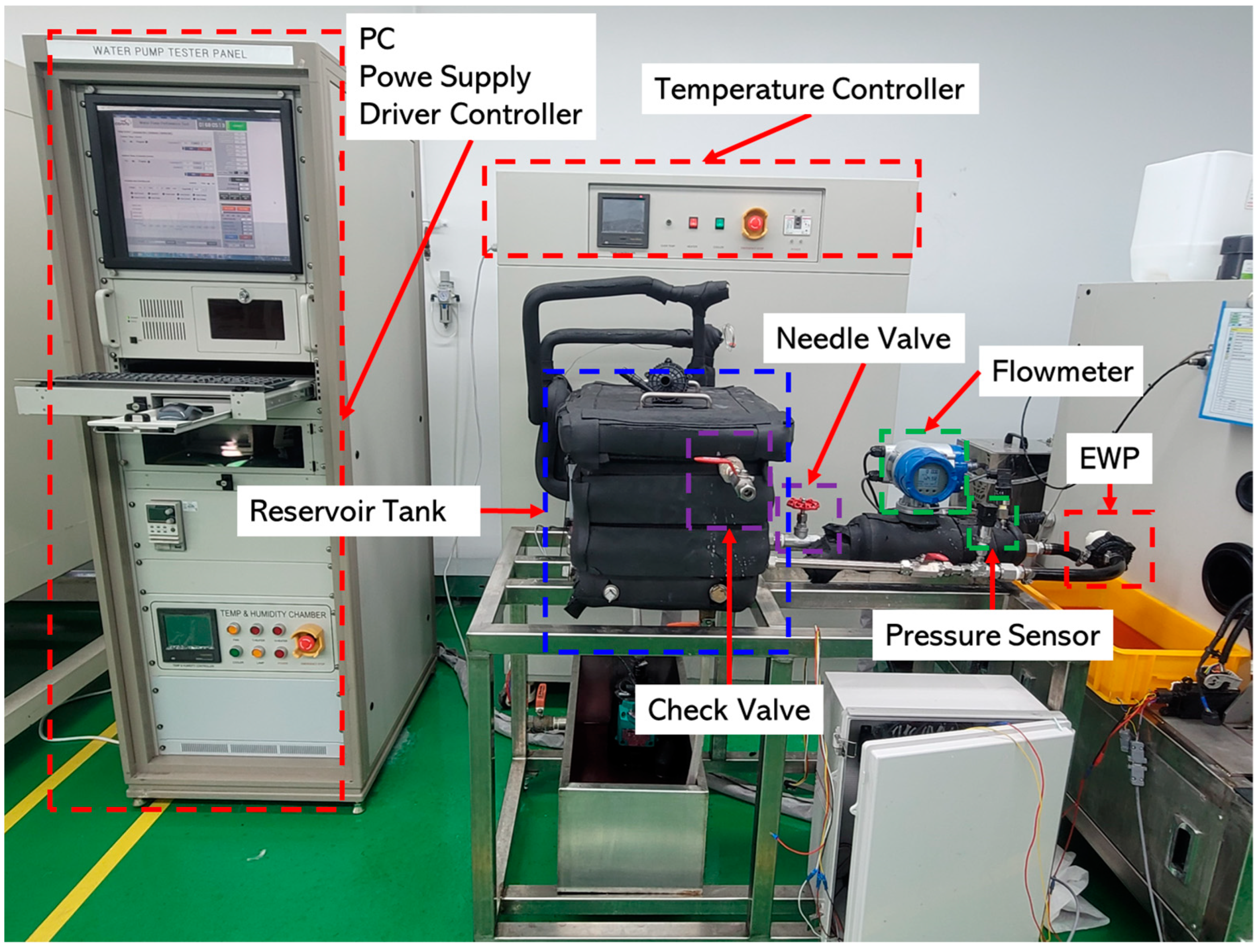
3.1. Experiment and Simulation Validation

An experiment was conducted to verify the EV water-pump simulation model with seven blades and an impeller outer diameter of 70 mm. Figure 6 and Figure 7 show the schematic and configuration of the experimental device, respectively. During the experiment, the motor voltage was fixed at 12 V, and the impeller rotation speed and flow rate were maintained at 3800 RPM and 14 LPM, respectively.
The experimental setup consists of the following:
  • The part that drives the impeller rotation;
  • Cooling passage;
  • Control device to regulate impeller rotation speed and coolant temperature;
  • Control unit to measure pressure and flow at the pump inlet and outlet.
A separate tank was installed to ensure a stable supply of coolant, which consisted of a heater and chiller to control the temperature of the coolant. Further, a needle valve, pressure sensor, and check valve were installed to regulate the flow rate and pressure at the pump outlet and prevent backflow. The motor had an adjustable rotational speed via a driver controller and power supply.
The coolant used in the experiment was a 1:1 ratio of ethylene glycol, which is commonly used in automobile antifreezes, and water. The coolant temperature and system pressure were maintained at 65 °C and 140 kPa, respectively; detailed information in this regard is presented in Table 4.
The reliability of the simulation results were verified by comparing them with experimental results. The experiment was performed using the equipment shown in Figure 6 and Figure 7 under the operating conditions listed in Table 4. The experimental conditions were the same as the analytical conditions, mainly operating at 3800 RPM and 14 LPM. The efficiency and head of the pump model were confirmed. The pump efficiency and head can be calculated using Equations (7) and (10), respectively.
η p u m p = Δ P × Q T × ω
Here, η p u m p represents the efficiency of the pump, Δ P refers to the pressure difference between the pump inlet and pool outlet, and Q is the flow rate at the outlet. Further, ω represents the angular velocity of the impeller and T represents the torque.
T = s r × τ ̿ × n ^ d S × a ^
Here, S represents all surfaces of the rotating body, τ ̿ represents the total stress tensor, and r and n ^ represent the unit vector and position vector perpendicular to the surface, respectively. In addition, a ^ represents the unit vector parallel to the rotational axis. The torque T and angular velocity ω acting on the blade are shown in Equations (9) and (10), respectively:
ω = 2 × π × R P M 60
H = P ρ × g
Here, H represents the head of the pump and ρ represents the density of the coolant. g is the acceleration owing to gravity.
The results are shown in Figure 8 to allow a visual comparison between the experimental and analysis results. Simulation and experimental results showed similar behavior under the same rotation and various flow conditions.
In this study, the simulation and experimental results for the pump head and efficiency were compared. For flow rates of 5, 10, 14, 15, and 20 LPM, the error rates in terms of pump head were 0.4%, 0%, 0.5%, 0.1%, and 1.2%, respectively, and, in terms of efficiency, were 0.35%, 0%, 2.5%, 2.3%, and 1.25%, respectively. This difference was attributed to the difference in differential pressure and flow rate of the pump.
In Table 5, the differential pressure and flow rate are shown for experiments and simulations at various flow rates. The external factors that occurred during the experiment explain the slight differences, as the simulations did not consider these external factors. Nevertheless, the simulation results of this study show a trend similar to the experimental results, and the error rates for efficiency and head are within 5%. This confirms the high reliability of the proposed simulation model.

3.2. Impact of Blade Number on Water Pump

Our study analyzed the effect of blade count on efficiency, head, and thrust of water pumps for EVs. Figure 9 provides a visual representation of the trends in pump efficiency, head, and thrust as the number of blades changes.
In Figure 9, the efficiency, head, and thrust of the pump tend to increase as the number of blades increases. Efficiency is 44.6% when the number of blades is 7 and improves by about 5.8% to 47.2% when the number of blades increases to 13. The head is 13.63 m when the number of blades is 7 and increases by about 3.4% to 14.1 m when the number of blades increases to 13. The thrust is 78.25 N when the number of blades is 7 and improves by about 5.7% to 82.76 N when the number of blades increases to 13. These results can be seen more clearly in Figure 10.
Figure 10 compares the velocity distributions with the size and distribution of unsteady flow decreasing and velocity increasing as the number of blades increases. Additionally, the efficiency of the pump increases as the kinematic properties of the fluid are improved and the supplied energy is converted effectively, increasing the pump head and thrust.

3.3. Effect of Water Pump Cavitation

As the number of blades increases, the speed increases, but this reduces the pressure in the inlet part of the impeller, causing a cavitation phenomenon. According to the research of AI-Obaiai [16], this cavitation phenomenon refers to the transformation of the liquid into gas, as the boiling point of the liquid decreases with a decrease in pressure in the inlet part of the impeller. In this process, small bubbles suddenly transform from liquid to gas. These bubbles return to the liquid state when the pressure increases again with the operation of the pump, at which time noise and vibration occur due to the sudden compression of the bubbles. These bubbles cause damage to pump parts because of the impact that occurs when they collide with the blades, which affects the durability of the pump. Therefore, it is important to minimize this phenomenon during pump operation as cavitation can cause damage to pump equipment. The cavitation phenomenon for different number of blades can be seen clearly in Figure 11.

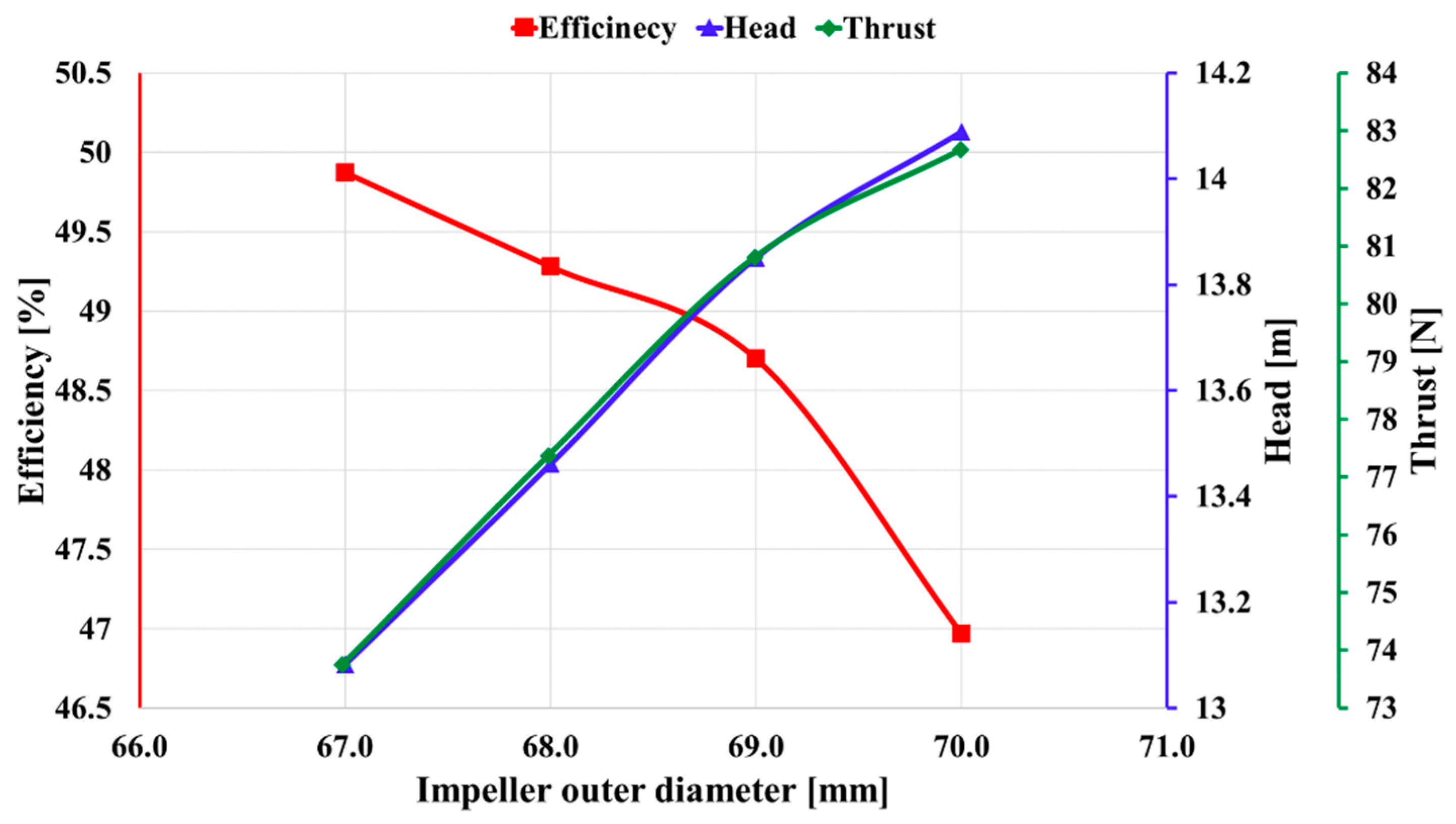
3.4. Impact of Impeller Outer Diameter on Water Pump

Based on the interpretation of the optimized blade count, we analyzed the impact on the pump by fixing the blade count at 11 and changing the outer diameter of the impeller. Figure 12 visually represents the trends in pump efficiency, head, and thrust according to the changes in the outer diameter of the impeller.
In Figure 12, the efficiency of the pump decreases with a change in the outer diameter of the impeller, despite a tendency to increase the head and thrust.
In terms of efficiency, when the outer diameter of the impeller increases from 67 to 70 mm, efficiency decreases from 49.87% by about 5.8% to 46.97%; the head increases from 13.08 m by about 7.6% to 14.08 m; and the thrust increases from 73.74 N by about 12% to 82.67 N. These results can be seen more clearly in Figure 13.
Figure 13 compares velocity distribution as the impeller diameter increases, confirming that the size and distribution of abnormal flow increase as the impeller diameter increases. This is because the change in fluid flow patterns interferes with the efficient movement of the fluid. As a result, with an increase in impeller diameter, efficiency tends to decrease and rotational resistance increases when the impeller rotates, consuming more energy in the process of pumping the fluid. This tends to increase the head and thrust. Based on the analysis results, the smallest impeller diameter of 67 mm is the most efficient but has the lowest performance, whereas the largest impeller diameter of 70 mm is the least efficient but has the best performance. The water pump for electric vehicles needs to consider both efficiency and performance. Thus, an impeller diameter of 68–69 mm, which balances efficiency and performance, is considered the optimal pump state. Therefore, based on a comprehensive analysis, it can be concluded that the optimal condition for the pump is 11 blades and an impeller diameter of 68–69 mm.

4. Conclusions

The modern automobile industry emphasizes environmental friendliness and efficiency, making it essential to improve the performances of various vehicle components. In particular, the cooling system is considered a critical component because it has a significant impact on the motor and battery efficiencies, lifespan, and overall performance of EVs. In this context, this study aimed to improve the performance and efficiency of a 104 W class centrifugal pump designed for EVs.
Accordingly, this study entailed a simulation-based analysis to elucidate the influence of the design variables, namely, the number of blades and impeller outer diameter, on the performance and efficiency of the pump.
The following conclusions can be drawn from this study:
  • As the number of blades increases, both efficiency and positive thrust tend to increase. In particular, when the number of blades increases from 11 to 13, efficiency increases of 5.8%, 3.4%, and 5.7% are observed, respectively. However, when the number of blades is 13, cavitation occurs, which can adversely affect the durability of the pump. For this reason, it was concluded the optimal state is reached when the number of blades is 11.
  • When the number of blades is fixed at 11, efficiency tends to decrease and performance increases with an increase in the outer diameter of the impeller. However, since an electric vehicle water pump must consider both efficiency and performance, the optimal state is attained with an impeller outer diameter of 68~69 mm, where efficiency and performance are balanced.
  • Therefore, based on a comprehensive analysis, it can be concluded that number of blades of 11 and impeller outer diameter of 68–69 mm determine the optimal condition for the pump.
The number of blades and the outer diameter of the impeller have a significant impact on the performance of the pump; thus, determining the optimal conditions under various operating conditions has become a major challenge. On the basis of these considerations, future research should focus on the performance under various operating conditions. We intend to perform a more detailed analysis and determine the optimal pump operating conditions. The results of this study are expected to contribute to the development of more efficient and stable water pumps.

Author Contributions

Conceptualization, H.J., D.H., H.L. and S.S.; investigation, H.J., H.L. and S.S.; writing—original draft preparation, H.J. and D.H.; writing—review and editing, J.H.; supervision, J.H. and H.L. All authors have read and agreed to the published version of the manuscript.

Funding

This research was supported by the “Regional Innovation Strategy (RIS)” through the National Research Foundation of Korea (NRF) funded by the Ministry of Education (MOE) (2021RIS-004) and This research was financially supported by the Ministry of Trade, Industry, and Energy (MOTIE), Korea, under the “Project for Research and Development with Middle Markets Enterprises and DNA(Data, Network, AI) Universities” (Development of Integrated Electric Vehicle Thermal Management System Operation Strategy and Efficiency Improvement Technology Using Neural Network-based MRAC Technique) (reference number P0024561) supervised by the Korea Institute for Advancement of Technology (KIAT).

Data Availability Statement

The data are contained within the article.

Acknowledgments

We would like to thank (www.editage.co.kr) for English language editing.

Conflicts of Interest

Authors Hyuntae Lee and Seongjin Son were employed by the company Coavis, Inc. The remaining authors declare that the research was conducted in the absence of any commercial or financial relationships that could be construed as a potential conflict of interest.

References

  1. Rogelj, J.; Den Elzen, M.; Höhne, N.; Fransen, T.; Fekete, H.; Winkler, H.; Schaeffer, R.; Sha, F.; Riahi, K.; Meinshausen, M. Paris Agreement climate proposals need a boost to keep warming well below 2 °C. Nature 2016, 534, 631–639. [Google Scholar] [CrossRef] [PubMed]
  2. Quadrelli, R.; Peterson, S. The energy–climate challenge: Recent trends in CO2 emissions from fuel combustion. Energy Policy 2007, 35, 5938–5952. [Google Scholar] [CrossRef]
  3. Teske, S.; Bratzel, S.; Tellermann, R.; Stephan, B.; Vargas, M. Net Zero: The remaining global market volume for internal combustion engines in light-duty vehicles under a 1.5 °C carbon budget trajectory. Energies 2022, 15, 8037. [Google Scholar] [CrossRef]
  4. Kumar, L.; Jain, S. Electric propulsion system for electric vehicular technology: A review. Renew. Sustain. Energy Rev. 2014, 29, 924–940. [Google Scholar] [CrossRef]
  5. Mathieu, R.; Briat, O.; Gyan, P.; Vinassa, J.-M. Comparison of the impact of fast charging on the cycle life of three lithium-ion cells under several parameters of charge protocol and temperatures. Appl. Energy 2021, 283, 116344. [Google Scholar] [CrossRef]
  6. Zhang, Z.; Yu, W.; Li, H.; Wan, W.; Zhang, W.; Zhuo, W.; Liu, Q. Heat transfer characteristics and low-temperature performance of a lithium-ion battery with an inner cooling/heating structure. Appl. Therm. Eng. 2023, 219, 119352. [Google Scholar] [CrossRef]
  7. Wang, H.; Tao, T.; Xu, J.; Mei, X.; Liu, X.; Gou, P. Cooling capacity of a novel modular liquid-cooled battery thermal management system for cylindrical lithium ion batteries. Appl. Therm. Eng. 2020, 178, 115591. [Google Scholar] [CrossRef]
  8. Mistruzzi, E. Investigation of Engine Coolant Loop Flow Modelling from a System Simulation Perspective. Master’s Dissertation, University of Windsor, Windsor, ON, Canada, 2019. [Google Scholar]
  9. Park, S.-J. Simulation of hybrid and electric vehicle thermal management system. Mag. Soc. Air-Cond. Refrig. Eng. Korea 2013, 42, 48–57. [Google Scholar]
  10. Fernández Oro, J.M.; Barrio Perotti, R.; Galdo Vega, M.; González, J. Effect of the radial gap size on the deterministic flow in a centrifugal pump due to impeller-tongue interactions. Energy 2023, 278, 127820. [Google Scholar] [CrossRef]
  11. Wu, C.; Pu, K.; Shi, P.; Wu, P.; Huang, B.; Wu, D. Blade redesign based on secondary flow suppression to improve the dynamic performance of a centrifugal pump. J. Sound Vib. 2023, 554, 117689. [Google Scholar] [CrossRef]
  12. Chen, W.; Li, Y.; Liu, Z.; Hong, Y. Understanding of energy conversion and losses in a centrifugal pump impeller. Energy 2023, 263, 125787. [Google Scholar] [CrossRef]
  13. Arun Shankar, V.K.; Umashankar, S.; Paramasivam, S.; Hanigovszki, N. A comprehensive review on energy efficiency enhancement initiatives in centrifugal pumping system. Appl. Energy 2016, 181, 495–513. [Google Scholar] [CrossRef]
  14. Capurso, T.; Bergamini, L.; Torresi, M. A new generation of centrifugal pumps for high conversion efficiency. Energy Convers. Manag. 2022, 256, 115341. [Google Scholar] [CrossRef]
  15. Kim, N.H. Analysis of flow characteristic in centrifugal pump. kfma 2019, 22, 56–61. [Google Scholar] [CrossRef]
  16. Ramadhan Al-Obaidi, A. Effects of different turbulence models on three-dimensional unsteady cavitating flows in the centrifugal pump and performance prediction. Int. J. Nonlinear Sci. Numer. Simul. 2019, 20, 487–509. [Google Scholar] [CrossRef]
  17. Sun, S.-K.; Zhao, B.; Jia, X.-H.; Peng, X.-Y. Three-dimensional numerical simulation and experimental validation of flows in working chambers and inlet/outlet pockets of roots pump. Vacuum 2017, 137, 195–204. [Google Scholar] [CrossRef]
  18. Medvitz, R.B.; Kunz, R.F.; Boger, D.A.; Lindau, J.W.; Yocum, A.M.; Pauley, L.L. Performance analysis of cavitating flow in centrifugal pumps using multiphase CFD. J. Fluids Eng. 2002, 124, 377–383. [Google Scholar] [CrossRef]
  19. Hornsby, C. CFD—Driving pump design forward. World Pumps 2002, 431, 18–22. [Google Scholar] [CrossRef]
  20. Cao, S.; Peng, G.; Yu, Z. Hydrodynamic design of rotodynamic pump impeller for multiphase pumping by combined approach of inverse design and CFD analysis. J. Fluids Eng. 2005, 127, 330–338. [Google Scholar] [CrossRef]
  21. Tan, L.; Zhu, B.; Cao, S.; Bing, H.; Wang, Y. Influence of Blade Wrap Angle on Centrifugal Pump Performance by Numerical and Experimental Study. Chin. J. Mech. Eng. 2014, 27, 171–177. [Google Scholar] [CrossRef]
  22. Xu, Z.; Kong, F.; Tang, L.; Liu, M.; Wang, J.; Qiu, N. Effect of blade thickness on internal flow and performance of a plastic centrifugal pump. Machines 2022, 10, 61. [Google Scholar] [CrossRef]
  23. Peng, G.; Chen, Q.; Zhou, L.; Pan, B.; Zhu, Y. Effect of blade outlet angle on the flow field and preventing overload in a centrifugal pump. Micromachines 2020, 11, 811. [Google Scholar] [CrossRef] [PubMed]
  24. Abo Elyamin, G.R.H.; Bassily, M.A.; Khalil, K.Y.; Gomaa, M.S. Effect of impeller blades number on the performance of a centrifugal pump. Alex. Eng. J. 2019, 58, 39–48. [Google Scholar] [CrossRef]
  25. Houlin, L. Effects of blade number on characteristics of centrifugal pumps. Chin. J. Mech. Eng. 2010, 23, 742. [Google Scholar]
  26. Jafarzadeh, B.; Hajari, A.; Alishahi, M.M.; Akbari, M.H. The flow simulation of a low-specific-speed high-speed centrifugal pump. Appl. Math. Modell. 2011, 35, 242–249. [Google Scholar] [CrossRef]
  27. Shojaeefard, M.H.; Tahani, M.; Ehghaghi, M.B.; Fallahian, M.A.; Beglari, M. Numerical study of the effects of some geometric characteristics of a centrifugal pump impeller that pumps a viscous fluid. Comput. Fluids 2012, 60, 61–70. [Google Scholar] [CrossRef]
  28. Kaewnai, S.; Chamaoot, M.; Wongwises, S. Predicting performance of radial flow type impeller of centrifugal pump using CFD. J. Mech. Sci. Technol. 2009, 23, 1620–1627. [Google Scholar] [CrossRef]
  29. Jeanty, F.; De Andrade, J.; Asuaje, M.; Kenyery, F.; Vásquez, A.; Aguillón, O.; Tremante, A. Numerical simulation of cavitation phenomena in a centrifugal pump. In Proceedings of the ASME 2009 Fluids Engineering Division Summer Meeting, B & C., Vail, CO, USA, 2–6 August 2009; ASME: New York, NY, USA, 2009; Volume 1, pp. 331–338. [Google Scholar] [CrossRef]
Figure 1. Centrifugal pump cross-section.
Energies 17 00853 g001
Figure 2. Centrifugal pump model flow field.
Energies 17 00853 g002
Figure 3. Centrifugal pump parameters.
Energies 17 00853 g003
Figure 4. Flow field mesh for water pump.
Energies 17 00853 g004
Figure 5. Mesh dependence test.
Energies 17 00853 g005
Figure 6. Schematic of the water pump experiment setup.
Energies 17 00853 g006
Figure 7. Water pump experiment apparatus.
Energies 17 00853 g007
Figure 8. Verification of simulation and experimental results for various flow rates (5, 10, 14, 15, and 20 LPM) and 3800 PRM. Experiment vs. simulation: (a) H-Q; (b) E-Q.
Energies 17 00853 g008
Figure 9. Performance curve according to the number of blades.
Energies 17 00853 g009
Figure 10. Velocity distribution according to the number of blades: (a) 7; (b) 9; (c) 11; (d) 13.
Energies 17 00853 g010
Figure 11. Cavitation phenomenon for different number of blades: (a) 11; (b) 13.
Energies 17 00853 g011
Figure 12. Performance curve as a function of impeller diameter.
Energies 17 00853 g012
Figure 13. Velocity distribution for impeller outer diameters of (a) 67 mm; (b) 68 mm; (c) 69 mm; and (d) 70 mm.
Energies 17 00853 g013
Table 1. Detailed design parameters for centrifugal pump.
ParametersSymbolsValuesUnits
Blade outlet angle β 45°
Blade wrap angle α 123°
Blade thickness t b 1.8mm
Blade number 7EA
Impeller inlet diameter D 1 16mm
Impeller outlet diameter D 2 13.6mm
Impeller outer diameter D 3 70mm
Impeller heightb6mm
Table 2. Coolant properties.
PropertiesValuesUnits
CoolantWater: Ethylene Glycol = 1:1-
Coolant Temperature65°C
Coolant density1045.03 k g / m 3
Coolant viscosity0.00136981 P a · s
Table 3. Boundary conditions.
Boundary ConditionsValuesUnits
Inlet pressure0kPa
Outlet Mass flow0.2438403333 k g / s
Rotation velocity3800RPM
Table 4. Experimental conditions.
ConditionsValuesUnits
CoolantWater: Ethylene Glycol = 1:1-
Coolant Temperature65°C
System Pressure140kPa
Motor Voltage12V
Rotational speed3800RPM
Table 5. Differential pressure at various flow rates.
Experiment (Q) Experiment   ( k P a )Simulation (Q) Simulation   ( k P a
5134.85135.28
10137.510137.51
14.3140.314139.65
15.3140.115139.91
20.5138.720140.38
Disclaimer/Publisher’s Note: The statements, opinions and data contained in all publications are solely those of the individual author(s) and contributor(s) and not of MDPI and/or the editor(s). MDPI and/or the editor(s) disclaim responsibility for any injury to people or property resulting from any ideas, methods, instructions or products referred to in the content.

