Abstract
With the progress of modern times, automobile technology has become integral to human society. At the same time, the need for energy has also grown. In parallel, the total amount of waste energy that is liberated from different parts of the automobile has also increased. In this ever-increasing energy demand pool, future energy shortages and environmental pollution are the primary concerns. A thermoelectric generator (TEG) is a promising technology that utilizes waste heat and converts it into useful electrical power, which can reduce fuel consumption to a significant extent. This paper comprehensively reviews automobile thermoelectric generators and their technological advancements. The review begins by classifying different waste heat technologies and discussing the superiority of TEGs over the other existing technologies. Then, we demonstrate the basic concept of and advancements in new high-performance TEG materials. Following that, improvements and associated challenges with various aspects, such as the heat exchanger design, including metal foam, extended body, intermediate fluid and heat pipe, leg geometry design, segmentation, and multi-staging, are discussed extensively. Finally, the present study highlights research guidelines for TEG design, research gaps, and future directions for innovative works in automobile TEG technologies.
1. Introduction
The economic development of any country requires significant energy inputs. Today, oil, coal, and gas provide about 80 percent of our energy needs. The annual report of the Energy Institute [1] indicates that the coal and natural gas consumption were 161.74 exajoules and 3.94 trillion cubic meters, respectively, in 2022. The International Energy Agency [2] reported that the global crude oil demand would be an average of 102 million barrels per day in 2023. This figure is ever-increasing. However, fossil fuels are not renewable and will run out within a few decades. Carbon dioxide is the main byproduct of the combustion of fossil fuels, which is responsible for environmental problems such as global warming, air pollution, water pollution, etc. The IEA stated that global CO2 emission from fuel combustion and industrial processes was 36.8 billion tons in 2022 [3], which was its highest annual level.
The transport sector is one of the significant users of fossil fuels. It consumes one-third of the world’s energy, and 85% is consumed by the road transportation sector [4]. An internal combustion engine (ICE), a continuous work-producing device, can convert only about 30–35% of the total energy into practical work. This indicates that nearly 60–65% of fuel energy is released into the atmosphere as waste heat [5]. This figure may vary depending on the engine type and different load conditions of the ICEs. Waste heat recovery technology utilizes the waste heat from ICEs and provides valuable work in mechanical or electrical power. Vázquez et al. [6] suggested that utilizing around 6% of engine exhaust heat would reduce fuel consumption by about 10%. Figure 1 shows a typical energy flow of an engine based on the fuel energy.

Figure 1.
Typical energy flow diagram of an engine [7].
A waste heat recovery system also decreases the alternator size, which consumes the shaft’s brake power. It is broadly categorized into two classes based on the power output mode. Organic Ranking cycles [8,9,10], vapor absorption refrigeration cycles [11,12,13], turbocharging [14,15], turbo-compounding [16,17], and Stirling engines [18,19] are the existing waste recovery systems which consume waste heat as input and create mechanical torque. On the other hand, thermionic generators [20] directly convert the heat energy into an electrical current.
Thermoelectric generators (TEGs) are solid-state semiconductor devices that produce a DC power output if a temperature difference exists. The working principle of a thermoelectric generator is based on three basic thermoelectric phenomena, namely, the Seebeck effect [21], the Peltier effect [22], and the Thomson effect [23]. Compared with other methods, a TEG has some inherent advantages, as it is a solid-state device, completely silent, zero-emission, compact, and capable of producing power from any heat source [24,25,26,27,28]. However, its broad commercialization is restricted by two main issues: a low conversion efficiency and high thermoelectric material costs [29].
The Seebeck effect was discovered in 1826 [30]. According to the literature, the study of automobile TEGs started in 1964 [31]. The massive investigation in this field began only in the 21st century, as pressure was imposed by different environmental regulatory bodies to enforce emission norms. Over the years, many researchers have focused on enhancing power outputs and conversion efficiency. On this occasion, several OEMs, such as BMW [32,33], Renault [34], Honda [35], Ford [36], and Nissan [37], have also concentrated their attention on this issue. But it is still preliminary, and no system has undergone mass production.
2. Working Principle
A metal plate contains free electrons. These electrons uniformly distribute throughout it. When one end is heated and the other end remains cold, the electrons at the hotter end move faster than the colder ones. Thus, more electrons move from the warm side to the cold end than those moving in the other direction. As a result, the hot end becomes deficient in electrons and positively charged with the cold end. This phenomenon causes the establishment of a potential difference between the two ends. If a conductor externally connects these two ends, a current will flow through the conductor due to the Seebeck effect (Figure 2). Thus, a metal plate with a temperature gradient across its two ends can act as a small electric generator, called a thermoelectric generator (TEG).
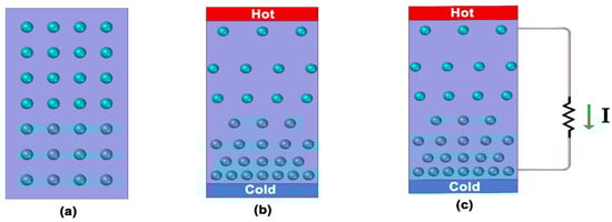
Figure 2.
Schematic diagram of (a) free electron distribution in metal plate, (b) free electron distribution when temperature gradient is induced, (c) EMF produced due to Seebeck effect.
However, the EMF induced by such a plate is extremely small (tiny, in the order of mV). Several such plates are required to be arranged in an electrical series connection, but thermally and in parallel, to enhance this voltage. Metal conductors can join their ends to connect the tiny cells in series, as shown in Figure 3. But the metal conductor also gets hot at the hot end and cold at the other end. So, a similar but opposite potential difference is set up in the metal conductors, and the advantage of a series connection is lost. This problem can be solved by introducing p-type and n-type semiconductor materials instead of the metal strip. In a pure (intrinsic) Si or Ge semiconductor, each nucleus uses its four valence electrons to form covalent bonds with its neighbors. At this stage, the net charge in the atom is zero. Now, if one of the atoms in the semiconductor lattice is replaced by an element with three valence electrons, such as Boron (B) or Gallium (Ga), the electron–hole balance changes. This system can only contribute three valence electrons to the lattice, leaving one excess hole. It becomes a positive charge, since holes will “accept” free electrons. This type of semiconductor is known as a p-type semiconductor.
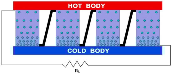
Figure 3.
Series connection of heated metal plate.
In another way, one of the lattice atoms is replaced by an atom with five valence electrons, such as arsenic (As) or phosphorus (P), which adds five valence electrons to the lattice. This implies that there is one excess electron in the lattice. So, the semiconductor yields are negatively charged in nature. This type of semiconductor is known as an n-type semiconductor. When the p-type and n-type semiconductors are heated at one end and cooled at the other, either the holes (vacant of electrons) or the free electrons will concentrate towards the cold end and thus produce a potential difference.
If the p-type and n-type semiconductors are thermally connected in parallel, as depicted in Figure 4, to construct a TEG, the potential difference that is created in them is opposite in orientation. Thus, the p-type semiconductor is negative at the hot end and positive at the cold end, while the n-type semiconductor is positive at the hot end and negative at the cold end. They can be connected electrically in series by joining their ends to augment the electric potential difference or voltage.
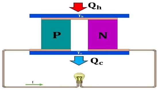
Figure 4.
A p-type and an n-type semiconductor are connected to form a TEG.
3. TEG Efficiency
The Seebeck effect produces an electromotive force in a circuit with two dissimilar wires with one heated junction. The Peltier effect is a reverse process to generate an electric current in a thermocouple that produces heating and cooling depending on its direction. The current direction and material create either absorbed or liberated heat for the temperature difference between any two points. Thermoelectric effects are the combination of these three effects. Thermoelectric generators act as heat engines [38]. The performance of the device is characterized by its efficiency [39]. The continuity equation for an invariant current through a variably heated thermoelectric material is
The current density and thermal gradient yield the electric field as
where and are the Seebeck coefficient and electric resistivity, respectively. The heat flux is obtained using Onsager’s principle and the Thomson condition:
The heat conduction equation for the steady state is expressed by
The volumetric heat generation rate is determined from Equation (2) by the dot product for the thermoelectric generator as
Combining Equations (3)–(5)’s results,
Equation (6) can further be simplified as
The mathematical expression of the Thomson coefficient is
We can assume that the Seebeck coefficient does not change with temperature, and then, Equation (7) becomes
Equation (9) reduces based on the negligibility of the radiation, convection at the surfaces, and electrical and thermal contact resistance for a one-dimensional thermoelectric generator module to
where x, A, and I represent coordinates from the hot to the cold junction, cross section, and the electrical current through a thermocouple, respectively. For the two boundary conditions, i.e., and , the temperature gradient is obtained at the hot junction from Equation (10) as
The rate of absorbed heat (Qh) at the hot junction for the N number of thermocouples can be expressed in terms of p-type and n-type thermal substances as follows:
Equation (12) can be finalized using Equation (11) as
where
where denotes the electrical resistance, and represents the thermal conductance. For the similar p-type and n-type thermocouples, the electrical resistance and thermal conductance become
The heat rate that evolves at the cold junction is written as
A thermoelectric module works like a heat engine between hot and cold temperatures. The net output power (W) from the module is obtained from the first law of thermodynamics:
Equation (17) can be expressed in terms of internal properties using Equations (13) and (16) as
Based on the electrical analogy, the net output power is defined by the external load resistance:
Comparing Equations (18) and (19) yields the total voltage drop (VN):
The electric current (I) can be determined from the above equation as
It can be noted that the current does not depend on the number of thermocouples. The voltage drop across the module is obtained from Equations (20) and (21) as
The output power is now calculated from Equations (19), (21), and (22):
The thermal or conversion efficiency can be defined as the ratio of the power output to the heat that is absorbed at the hot junction:
Equation (24) is expressed using Equations (13), (21), and (23) as
where
The short circuit provides the maximum current for Rex = 0. This maximum current (Imax) can be determined from Equation (21):
The extremum voltage appears under the open circuit condition, I = 0, and is obtained from Equation (20) as
The extremum work is evaluated to differentiate Equation (3) based on the ratio of the load resistance to the internal resistance, equating to zero. The optimality condition is = 1. Therefore, the extremum power output is
The extremum conversion efficiency condition is determined from Equation (25):
The extremum conversion efficiency is evaluated from Equations (25) and (30) as
Therefore, the system’s efficiency depends on the temperature difference between the two ends, the TEG’s working temperature, and the non-dimensional figure of merit.
4. Figure of Merit
The fabrication of a TEG requires different metal and semiconductor materials. The performance of the thermoelectric material depends on the selection of material for a particular operating temperature and the material synthesis technique. The main factor determining a thermoelectric material’s maximum efficiency is the thermoelectric figure of merit. A material with a higher value of this merit indicates that the material is more efficient. The mathematical expression of the figure of merit is
The figure of merit is a temperature-dependent property. The dimensionless figure of merit is as follows:
It can be noted that the ZT value of a material improves in three ways:
- (i)
- The thermal conductivity of the material can be reduced to maintain a high temperature gradient across the two ends.
- (ii)
- Increasing the electrical conductivity reduces the resistivity and Joule heating.
- (iii)
- Enhancing the Seebeck coefficient leads to a high potential difference.
The primary objective in the TEG research field is the improvement of their output and conversion efficiency. Several strategies are mainly considered, including developing high-performing TEG materials, enhancing the heat transfer rate on both the hot and cold sides, and having a proper thermocouple design to achieve this goal. The following section presents a comprehensive review of the technological advancements in automobile TEG systems. The detailed discussion can be divided into three parts:
- (a)
- Improvement of TEG materials.
- (b)
- Implementation of highly efficient heat exchangers.
- (c)
- Structural improvement of TE legs.
Real-life applications and the impact of the actual operating conditions are discussed in a separate section. Finally, a conclusion is drawn, indicating the technical gaps in and future aspects of TEG technology.
5. Thermoelectric Materials Used in Automobiles
The selection of appropriate materials is essential, as the performance of the TEG system depends on the TEG materials. So, the selection of suitable TE materials is critical. TE materials should have a high conversion efficiency; appropriate thermoelectric and mechanical properties; not be toxic; and be ecofriendly, low-cost, and easy to synthesize. For convenience, TE materials can be divided into seven categories, BiTe-based, SnSe-based, CuSe-based, multi-component oxides, half-Heusler alloys, organic and inorganic composites, and GeTe/PbTe-based materials.
5.1. BiTe-Based Materials
Bismuth telluride (BT)-based compounds are high-performing TE materials that are suitable at room or nearly room temperature. They have excellent thermoelectric as well as mechanical properties. Zhu et al. [40] synthesized a p-type Bi0.5Sb1.5Te3 bulk material through the cold-sintering method. The cold-sintering reduces the grain size, resulting in a low lattice thermal conductivity. The results show that the material has a maximum ZT value of 0.56 at 450 K. Shi et al. [41] incorporated Cu2Te into the polycrystalline p-type Bi0.3Sb1.7Te3 (BST) lattice and improved the TE performance through the evolution of intrinsic point defects. BST-Cu2Te samples exhibit a maximum ZT value of ∼1.15 at 423 K and an average ZT value of ∼1.12 in the temperature range of 350–500 K. Zhang et al. [42] synthesized a p-type (Bi, Sb)2Te3 base material by adopting a stepwise optimization technique to enhance its thermoelectric (TE) performance. They obtained a maximum ZT value of 1.53 at 350 K and an average ZT value of 1.31 in the temperature range of 300–500 K for Bi0.4Sb1.6Te0.95Se0.05 + 0.10 wt% Ag8GeTe6 configuration. Moreover, when a temperature difference of 245 K was maintained, the sample exhibited a conversion efficiency of 6.3%.
Shen et al. [43] exhibited that both Mn alloying at the Bi site and Ge doping at the Si site can enhance the carrier concentration and bipolar effect elimination in Bi2Si2Te6. Their results show that both Bi1.98Mn0.02Si2Te6 and Bi2Si1.8Ge0.2Te6 exhibit a maximum ZT value of 1 at 773 K. Gayner et al. [44] adopted a solution method to synthesize bulk heterophase structures of Bi2Te3−Te. They identified an n-type Bi2Te3, which has a maximum figure of merit value of 1.30 at 450 K and an average figure of merit value of 1.14 at 500 K.
5.2. SnSe-Based Materials
Tin selenide and its associated TE materials can attract the researcher’s attention due to their ultralow thermal conductivity and high power factor. Moreover, they have isentropic TE properties. Shen et al. [45] prepared MoCl5-doped n-type polycrystalline SnSe by melting and hot-pressing. The doping enhanced the carrier concentration, caused the increase in multipoint defects, and reduced the thermal conductivity. A ZT value of 0.66 was achieved for SnSe0.95-1%MoCl5 at a temperature of 773 K. Abbas et al. [46] synthesized an n-type polycrystalline SnSe with doping of weak anisotropic I by utilizing the mechanical alloying (MA) and spark plasma sintering (SPS) methods. They found that the adopted technique is beneficial for anisotropy. They obtained a maximum ZT value of ≈1.02 at a temperature of 723 K for 2% I doping. An n-type SnSe0.95-1.5mol% NdCl3 sample was fabricated by Zhang et al. [47] using the combined method of melting and SPS. They demonstrated that excessive NdCl3 doping may reduce the thermal conductivity. Their results showed that the SnSe0.95-1.5 mol% NdCl3 sample achieved a maximum ZT value of 1.3 at a temperature of 773 K.
Mao et al. [48] prepared a Pb/I co-doped n-type polycrystal SnSe incorporated with carbon nanotubes. Integrating multi-walled carbon nanotubes improved the ZT value to ∼1.0 at 773 K. Moreover, they act as a binder to enhance the sample’s mechanical properties. Polycrystalline SnSe2-xBrx was fabricated by Nisar et al. [49], utilizing the SPS and MA approaches. They improved the power factor to approximately 755 μWm−1K−2 at 573 K. A maximum ZT value of 0.59 was obtained for SnSe1.95Br0.05 at a temperature of 748 K. Li et al. [50] fabricated polycrystalline SnSe material with doping of PbBr2 by melting and hot-pressing. The PbBr2 dopant significantly increased the carrier concentration and electrical conductivity. A maximum ZT value of 0.54 was determined for SnSe0.95 -3%PbBr2 at 793 K.
5.3. CuSe-Based Materials
CuSe-based materials have low thermal conductivity and good thermoelectric properties. However, they have a complex crystal structure. Mac et al. [51] used mechanical alloying and solid-state reaction techniques to synthesize Sb-doped Cu2Se1-xSbx. A peak ZT value of 1.22 was achieved for the sample when the Sb-doped level was 0.02%. Patel et al. [52] adopted an elementary co-precipitation strategy to fabricate Ni- and Zn-doped CuSe. They obtained an optimum ZT value of 1.28 for CuSe-10% Zn nanoparticles at 523 K. Zhao et al. [53] fabricated a Cu2Se alloy with the introduction of Mxene by utilizing the hydrothermal method and the vacuum hot-pressing method. The results show that at 923 K, Cu2Se + 0.20 mol% MXene provides the maximum ZT value of 1.77.
Rapaka et al. [54] synthesized Cu2Se–1wt% graphene nanocomposites successively by chemical reduction and simple mechanical grinding. The Cu2Se−1 wt% graphene sample provides a maximum power factor of 1250 μWm−1 K−2 at a temperature of 450 °C. Yang et al. [55] synthesized an Al-doped Cu2Se thin film using magnetron co-sputtering deposition. The result shows that the Al introduction enhances the Seebeck coefficient, and a maximum ZT value of 0.76 was noticed at 275 °C. Bhat et al. [56] prepared Cu2-xBixSe monoclinic crystals utilizing the solid-state reaction technique. A Cu1.988Bi0.012Se sample provides a maximum power factor of 1474 μWm−1K−2 at a temperature of 700 K.
5.4. Multi-Component Oxides
Oxide TE materials are low-cost, eco-friendly in terms of manufacturing, and chemically stable. But they have moderate TE properties compared to traditional ones. Ahmed et al. [57] adopted a dual mechanism of optimization of the carrier concentration of La doping and introduced nanoscale porosity into the bulk sample of SrTiO3. The results show that the technique significantly improves the power factor, achieving a ZT value of 0.26 ± 0.063 at 850 K. Zheng et al. [58] fabricated polycrystalline Ca3-x-yTbxAgyCo4O9 (where x = y = 0, 0.01, 0.05, or 0.08) through the sol-gel and SPS methods. The results highlight that the x = y = 0.01 configuration is the optimum situation, giving a corresponding ZT value of 0.22 at 800 °C. Hira et al. [59] synthesized polycrystalline Ca3-2yNa2yCo4-yMoyO9 (0 ≤ y ≤ 0.10) by applying the traditional solid-state chemistry process. The dual doping technique can improve electrical conductivity and the Seebeck coefficient and reduce thermal conductivity. The results show that the y = 0.025 configuration exhibits a maximum PF of ∼3.2 × 10⁻⁴ Wm−1K−2 with a corresponding ZT value of 0.27 at 1000 K.
Zhang et al. [60] prepared polycrystalline Ca3-xAgxCo4-yFeyO9 (x = 0, 0.05; y = 0, 0.1, 0.2, 0.4) by co-doping Ag and Fe using the sol-gel method with the SPS method. The results indicate that the x = 0.5, y = 0.2 configuration exhibits a peak ZT value of 0.25 at 1000 K. Wu et al. [61] adopted sol-gel synthesis, Ni doping, and the rational annealing method to enhance the thermoelectric (TC) performance of nanostructured double perovskite Pr1.8Sr0.2CoFeO6. Rational annealing reduces the pores in the matrix and improves the electrical conductivity, while Ni doping enhances the hole concentration. A maximum figure of merit of 0.085 was obtained at 573 K for the Pr1.8Sr0.2CoFe0.95Ni0.05O6 configuration. Akram et al. [62] constructed a single-phase Na-doped Sodium Cobalt Oxide (NaxCoO2) using the sol-gel method. The major output highlights that the Seebeck coefficient, electrical conductivity, and thermal conductivity are amplified with the increase in Na content. A high merit value of 1.24 was determined at 1010 K, which is 28% more than for an undoped one.
5.5. Half-Heusler Alloys
Half-Heusler alloys have a high power factor and are suitable for middle- to high-temperature applications. Van Du et al. [63] fabricated Sb-doped half-Heusler Ti0.5Zr0.5NiSn1-xSbx alloys using arc-melting, melt-spinning, and SPS techniques. The results revealed a maximum ZT value of 1.2 when the temperature was 847 K for a 1.25% Sb-doped sample. However, when a temperature range of 300 K to 847 K was maintained, the thermoelectric conversion efficiency was 12.8%. Tan et al. [64] synthesized Ti-doped Nb0.8Ti0.2FeSb half-Heusler alloys by successive processes of levitation melting, ball milling, and SPS. They demonstrated that Ti doping enhances the power factor, reduces the thermal conductivity, and achieves a maximum ZT value of 0.9 at 973 K. When a temperature difference of 700 K was applied across a unileg device of Nb0.8Ti0.2FeSb, it exhibited a thermoelectric conversion efficiency of 10.6%. Kahiu et al. [65] fabricated Nb0.8Ti0.2Fe1+x Sb1-x samples employing Density Functional Theory (DFT). The determined results show that the x = 0.03 sample exhibits an enhanced Seebeck coefficient and a maximum power factor value of 50.3 μWcm−1 K at 373 K, with an improvement of ∼46% compared to the x = 0.00 and 0.05 configurations. Wang et al. [66] studied the thermoelectric properties of p-type and n-type pseudo-ternary Ti (Fe, Co, Ni) Sb-based half-Heusler alloys by changing the ratio of Fe/Co/Ni. From the results, the power factor was improved with the improvement in the carrier concentration and the density-of-state effective mass. A peak ZT value of 0.65 and 0.85 was obtained at 973 K for the n-type Ti0.8Hf0.2Fe0.3Co0.2Ni0.5Sb and p-type Ti0.8Hf0.2Fe0.5Co0.15Ni0.35Sb, respectively.
Zhang et al. [67] analyzed half-Heusler TiNiSn by a series of sieves and powder sintering. The improved energy filtering effect that was induced by a reduced average grain size enhanced the absolute value of the Seebeck coefficient. The obtained results indicate a maximum ZT value of 0.84 at 820 K. They also suggested grain boundary engineering, which is an effective method for enhancing the thermoelectric performance of half-Heusler compounds. Sattar et al. [68] predicted a series of vanadium-based half-Heusler VXTe (X = Cr, Mn, Fe, Co) alloys by utilizing first-principles computation and the semiclassical Boltzmann transport theory. The predicted alloys have significantly lower lattice thermal conductivity and a high power factor, with a high ZT value of 1.2 at 1000 K.
5.6. Organic–Inorganic Composites
Organic–inorganic materials have low thermal conductivity and low toxicity, and they are lightweight, but their ZT value is minimal, which makes them unsuitable for practical application. Liang et al. [69] synthesized an organic–inorganic superlattice of hybrid tetrabutylammonium-WSe2 (TBA-WSe2) through the electrochemical process. This material has an enhanced power factor with a maximum figure of merit value of 0.25. Qu et al. [70] fabricated n-type Ta4SiTe4/PVDF/GDY composite films by the chemical reaction between semiconducting graphdiyne (GDY) and Ta4SiTe4. The results exhibit a peak ZT value of 0.2 at a temperature of 300 K for Ta4SiTe4/PVDF/GDY. Liang et al. [71] created an organic–inorganic superlattice hybrid of SnSe2 by introducing organic material into the lattice. The results show a peak ZT value of 0.34 at 342 K. Wang et al. [72] produced an n-type poly [Nax(Ni-ett)] by utilizing the one-step solution method and showed a maximum ZT value of 0.04 at 400 K.
5.7. GeTe/PbTe-Based Materials
GeTe and PbTe are suitable for medium temperatures ranging from 300 to 900 K. They have low thermal conductivity, good strength, and a high figure of merit. Wang et al. [73] examined n-type InxAl0.02Pb0.98Te by co-doping indium and aluminum in PbTe, utilizing high-pressure synthesis and the SPS method. They determined that optimal InxAl0.02Pb0.98Te exhibits a maximum ZT value of 1.3 at 763 K and an average ZT value of 1, with a thermoelectric efficiency of 14%. Wang et al. [74] fabricated a high-performing n-type PbTe-based material by successive doping of excess Pb, excess Ag, and I elements. It can be observed that Pb1.01Te0.998I0.002 + 0.002Ag exhibits a peak ZT value of ~1.5 at 773 K and an average ZT value of ~1.0 for the temperature range of 300−773 K. Lv et al. [75] produced a Na-doped ternary Pb1-xNaxTe material by introducing an intentional cationic vacancy in it to improve the TE properties. They investigated the Pb0.95Na0.04Te sample, which had a maximum ZT value of ~2 at a temperature of 823 K.
Chen et al. [76] synthesized a single-crystal Ge1–xInxSb2Te4 through the Bridgman method. They maximized the non-dimensional figure of merit for an average ZT value of 0.68 at a temperature range of 323–773 K. Si et al. [77] adopted a decoupling mechanism to introduce multi-walled carbon nanotubes (MWCNTs) into Bi-doped GeTe. The embedding of MWCNTs enhances the power factor and reduces the thermal conductivity. They obtained a maximum ZT value of ~2.3 at 723 K and an average ZT value of ~1.43 in the temperature range of 323–773 K. Yang et al. [78] fabricated (Ge0.97Zn0.02In0.01Te)0.97(Bi2Te3)0.03 with co-doping of Bi and Zn. Bi-doping improves electronic properties and reduces thermal conductivity, while Zn doping allows it to maintain a high-power factor. In-doping brings the thermal conductivity to a lower level. This study highlighted that a maximum ZT value of 2.06 and a mean ZT value of 1.30 were obtained. Kim et al. [79] studied the impact on the TE performance of GeTe due to the co-doping of Al and Bi into it. The obtained result was a peak ZT value of ~1.95 at a temperature of 673 K.
An effort is made to achieve a maximum ZT value for different materials corresponding to a temperature, as depicted in Table 1. A higher ZT value is always desirable for higher TEG performance; thus, this study is significant. It can be concluded from this table that the maximum ZT value of a material depends on the temperature.

Table 1.
Maximum ZT value of different materials.
6. Heat Exchanger Design in Automobile Applications
Enhancing the temperature difference across the thermoelectric module (TEM) improves the waste heat recovery system’s efficiency. A high-temperature gradient can be maintained when the heat exchangers absorb as much heat as possible from the engine exhaust and liberate as much as possible into the cooling fluid. However, the thermal resistance across the heat exchangers and the fluid restricts the heat transfer rate. As a consequence, a lower temperature difference limits the TEG’s performance. Therefore, a strategy can be adopted to enhance the heat transfer rate by optimizing the heat exchanger’s structure. Figure 5 shows a schematic diagram of the TEG system coupled with the converging heat exchanger. Demir and Dincer [123] demonstrated a numerical model of a TEG coupled with a shell and tube heat exchanger. They demonstrated that the exhaust temperature and flow rate influence the system’s power capacity. The generated power was augmented by 90.6% as the exhaust temperature and mass flow rate increased by 15% and 24%, respectively. A correlation equation of the power with the system parameters was also developed. Quan et al. [124] designed a TEG system with a chaos-shaped brass heat exchanger mounted on an application for a sports utility vehicle (SUV). The experimental results predicted a maximum conversion efficiency of 1.03%. Asaduzzaman et al. [125] presented a model of an automobile TEG system, and a comparison was made of the performance when it was coupled with two different types of triangular heat exchangers that were constructed with copper and steel materials. The results showed an augmentation in power output of around 48%. Hong et al. [126] designed a three-compartment rectangular muffler with a heat exchanger installed at the center compartment. Their results showed enhanced exhaust flow distribution and temperature uniformity on the modified muffler system’s cross-sections. Their experiment also revealed that the discrepancies in the maximum temperature difference in the system decreased by 72.2% to 93.9% compared to that of a system with no deflecting plates in the first compartment. Lu et al. [127] studied a system of heat exchangers with a muffler in three different configurations to augment the heat transfer rate and reduce the back pressure loss that was imposed during the exhaust heat recovery using a TEG. A test bench was also developed and investigated under different vehicle operating conditions. It was observed that the two-inlet two-outlet system showed better flow distribution, uniform temperature distribution, enhanced heat transfer, and a higher surface temperature than the two-inlet two-outlet system and the empty cavity system. Kumar et al. [128] studied the effect of various heat exchanger designs on TEG performance, consisting of eighteen TEMs. The CFD-based results indicated that the rectangular heat exchanger outperformed the triangular and hexagonal designs. They also set up an experimental model to validate different parameters.
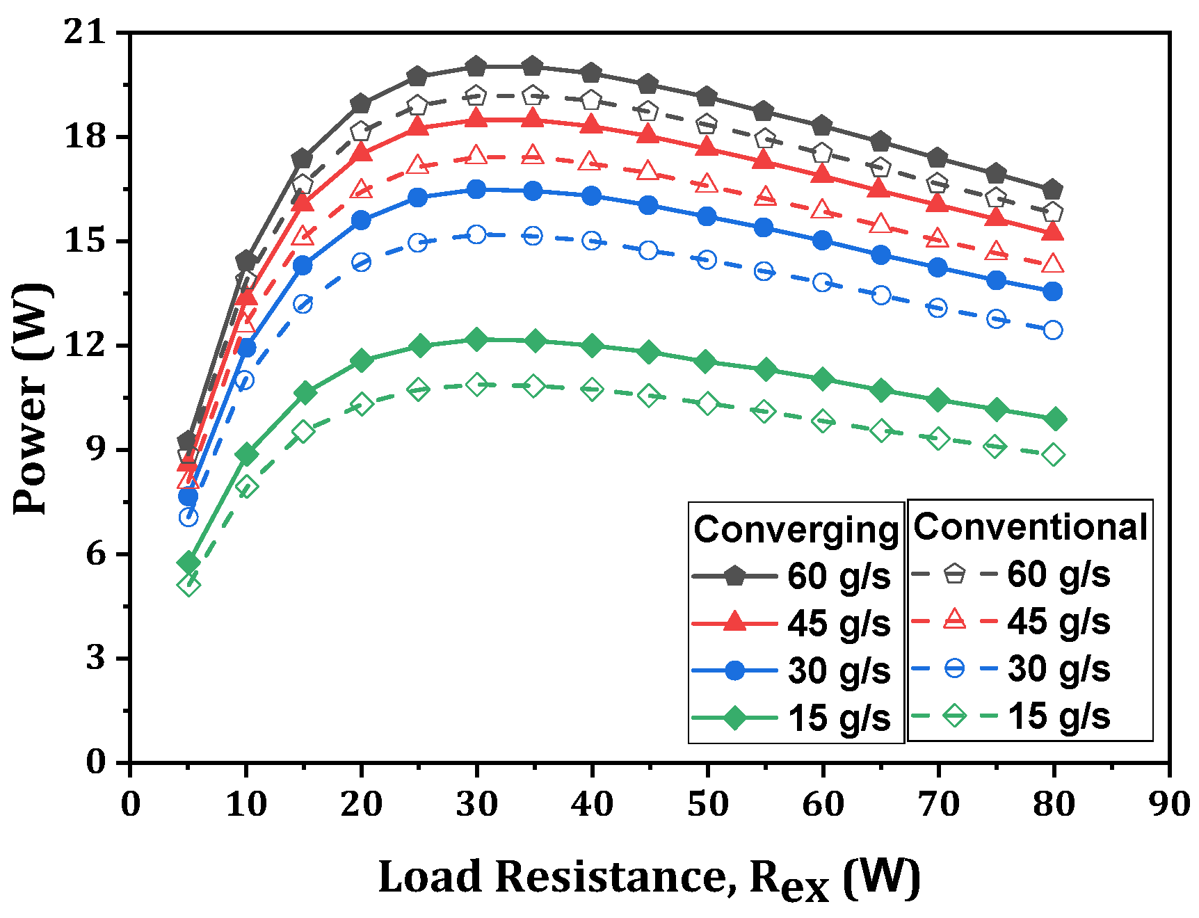
A CFD-based numerical model of a converging heat exchanger was developed by Luo et al. [129], and a study was conducted comparing this with a conventional heat exchanger. They found that a converging thermoelectric generator system provides a higher output power, more uniform temperature distribution, and, simultaneously, less induced back pressure loss than a system with a conventional structure. However, the increasing trends in the performance of converging TEG systems are augmented by an increment in air temperature and a reduction in mass flow rate. They found that the converging thermoelectric generator can generate 5.9% more power than a conventional one [130]. A good agreement between the numerical and experimental results was observed, with a maximum deviation of 2.4% in the output power. Figure 6 compares the output power of converging and conventional TEGs with variations in load resistance and fluid flow rate. At an optimum condition, a maximum output power was obtained at a particular load resistance. Therefore, the imposed design resistance is significant in order to produce maximum power.
Different auxiliary elements that are embedded in the heat exchanger can enhance the heat transfer effectiveness. In the following section, we discuss some of these types of systems.
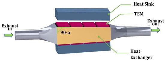
Figure 5.
Schematic diagram of TEG system with converging heat exchanger [130].
Figure 5.
Schematic diagram of TEG system with converging heat exchanger [130].

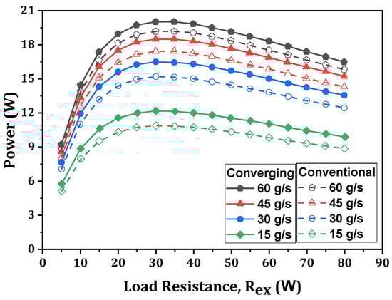
Figure 6.
Comparison of power output between converging TEG and conventional TEG with load resistance [130].
Figure 6.
Comparison of power output between converging TEG and conventional TEG with load resistance [130].
6.1. Metal Foam
The heat transfer rate in heat exchangers can be significantly improved by introducing metal foam in the flow passage of heat exchangers. Metal foams were developed to address a problem in structural application. However, today, it is primarily used for issues in thermal management applications. They are becoming a prominent component in thermoelectric generators due to their light weight, high rigidity, and large accessible surface-area-per-unit volume.
Buonomo et al. [131] performed a numerical analysis of the effect of a partially filled exhaust gas channel with metal foam on the performance of a TEG. They considered aluminum foam, along with the combination of three different porosities and three different pore densities. Figure 7 depicts the variation in the exhaust gas’s mass flow rate for a TEG with metal foam at various pore densities and 97.5 percent porosity, with the electric power, pressure drop, net electric power, and thermoelectric efficiency. The results highlight that the average hot side temperature escalates with the increase in foam thickness and porosity reduction. The pressure drop that was evaluated in the system augments with the increasing trends of pore density and foam thickness, while it decreases with increased porosity. The system’s effectiveness improved with an increasing exhaust flow rate but remained unchanged at different pore densities. Their study reveals that the system’s effectiveness for a stipulated condition may increase by 283% compared to when a system has no metal foam. They suggested that a foam thickness of three-eighths of the total flow passage should be the optimum foam thickness. Li et al. [132] demonstrated a test system to investigate the performance of a thermoelectric generator under the influence of a porous metal foam being embedded in the core flow region. The convective heat transfer coefficient and output power were enhanced with the increment in pore densities of the foam metal. For a stipulated condition and at a pore density of 20 PPI and a filling rate of 75%, the convective heat transfer coefficient became four times higher, and the output power doubled compared to the unfilled case. However, a pressure drop was unavoidable and increased with the foam metal’s pore density. Their experiment highlighted that, at the maximum flow rate, the pressure drop was almost four times and ten times higher when the filling rates were 50% and 75%, respectively. Figure 8 depicts the output power depending on the pore density, current, and filling rate. There is an optimum current for which the power output reaches a maximum value in any design situation. This is a favorable condition for implementation.
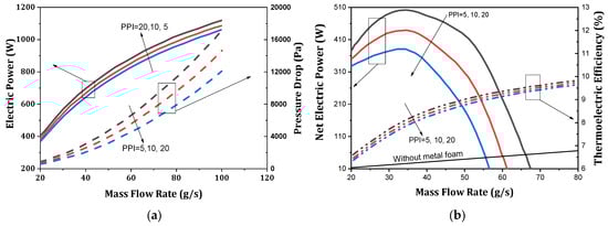
Figure 7.
Variations in mass flow rate of exhaust gas for TEG with metal foam of various pore densities and 97.5 percent porosity: (a) electric power and pressure drop and (b) net electric power and thermoelectric efficiency [131].
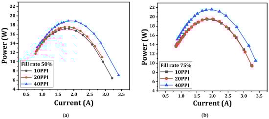
Figure 8.
Output power of thermoelectric generator as a function of current with different filling ratio and different pore density [132]. (a) Filling rate 50%, (b) filling rate 75%.
Nithyanandam and Mahajan [133] predicted the performance of an automobile TEG coupled under the influence of a wide range of porosities and pore densities of foam material. Didymium-based ternary skutterudite was used by them as a thermoelement. Their study reveals that, for each pore density of metal foam, there is a critical gas flow rate, and beyond this value, the net power output falls below a value when the system is embedded with no metal foam. They also suggested that a highly porous and lower pore density system provides the maximum net power output. The maximum power output is enhanced by 5.7 to 7.8 times when the system is embedded with metal foam. However, using metal foam significantly enhanced the variation in efficiency and the power that was generated by TEMs at different axial positions. Figure 9 illustrates a TEG that is integrated with metal foam. Bai et al. [134] demonstrated a numerical simulation model to predict the performance of a TEG system coupled with metal foam embedded in an octagonal heat exchanger. The study’s results showed that metal foam has excellent potential for higher temperature distribution and noise reduction ability. It has been observed that, as the porosity is gradually reduced, the output power gradually increases, reaches its maximum at an optimum porosity, and then declines. They also suggested that an increasingly thick metal foam will lead to a higher temperature difference and output power.
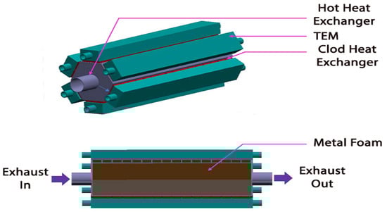
Figure 9.
TEG integrated with metal foam [133].
Lu et al. [135] studied a rectangular offset strip fin heat exchanger and a metal foam-embedded heat exchanger and their influence on TEG performance. The results show an optimum fin structure for maximum power in the strip fin heat exchanger, depending on the operating conditions. Low porosity and a low porous density would be the optimal metal foam characteristics in the heat exchanger structure. The results also showed that metal foam embedding can be more beneficial for power production than the strip fin heat exchanger. Li et al. [136] experimentally studied the effect of metal foam being filled in the core flow region on the performance of a thermoelectric generator. A copper metal foam with two different porous densities was considered, and its effect on the performance of three different thermoelectric modules was investigated. From the results, it can be seen that the maximum Nusselt number in the passage can be enhanced around four times, and the maximum power can also be enhanced up to 300% under the influence of metal foam in the flow passage.
6.2. Extended Surface
A surrogate-model-based optimization method was adopted by Wang et al. [137] for the fin distribution to maximize the generated power from a TEG system. They developed a CFD model of the heat exchanger, and different fin parameters were optimized to enhance the temperature uniformity and minimize the pressure drop. The results display that the variance in the temperature decreased from 242 to 208, and the back pressure loss decreased from 4950 Pa to 984 Pa in the optimized design. The internal flow field distribution for a heat exchanger coupled with an automobile TEG was investigated by Tang et al. [138]. They proposed a numerical model of the TEG system, and the results were validated experimentally. They suggested three heat exchanger configurations with three different fin orientations. They conducted a sensitivity analysis to evaluate the fin and heat exchanger’s inlet parameters. Their results show that the induction of fins improved the surface temperature uniformity and the average heat transfer coefficient. They suggested that a uniform fin inclination heat exchanger configuration offers better performance than the other two. Borcuch et al. [139] proposed a mathematical model to investigate the influence of the design parameters of the hot side of a hexagonal heat exchanger on the operational parameters of a thermoelectric generator. Six different fin configurations, including five and seven internal fins on each wall, and three fin geometries were examined. The results demonstrated that the equal fin configuration produces the maximum net power and conversion efficiency, including the maximum back pressure loss. They also suggested that the maximum output power and highest efficiency were not obtained at the most uniformly distributed temperature, and it should be one of many parameters for system analysis. A comparative study between a twisted-fin cylindrical heat exchanger and another with a spiral fin was conducted by Wang and Ma [140]. The model was developed using a CFD simulation platform. They studied the different thermal characteristics of the heat exchanger under different acceptable profile parameters. They also pointed out that the spiral-fin heat exchanger TEG system provides better thermal performance than the twisted-fin heat exchanger. Still, the back pressure loss is much more significant in the spiral-fin configuration, and a spiral-fin heat exchanger with a variable pitch provides better thermal performance than the other one. However, the back pressure increases further in the new heat exchanger. Figure 10 shows the effect of fin thickness on the temperature uniformity coefficient and back pressure for spiral- and twisted-fin configurations. A reversed result trend indicates that the parameters are dependent on the fin configuration.
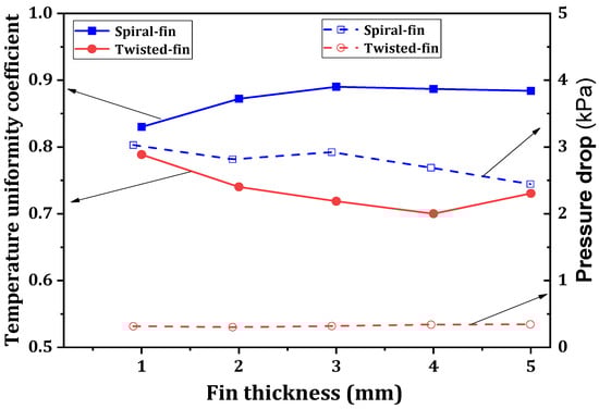
Figure 10.
Temperature uniformity coefficient and back pressure for spiral- and twisted-fin configurations depending on fin thickness [140].
Figure 11 presents a schematic diagram of a folded plate heat exchanger. Su et al. [141] constructed a three-segment heat exchanger with a folded-shaped internal structure to enhance an automobile TEG’s efficiency of exhaust waste heat recovery. The heat exchanger is designed to increase the number of folded plates in the direction of the exhaust flow for a uniform temperature drop. They demonstrated that a multi-objective genetic algorithm and surface methodology optimization techniques are efficient heat exchanger design tools. The predicted results confirm that the dimensions of the heat exchanger affect the surface temperature and thermal uniformity. They also suggest that the heat exchanger design can be developed based on the displacement and power of the engine and different drive cycles. A CFD-based structural optimization was carried out by Deng et al. [142] for various three-dimensional models of heat exchangers with different internal structures, lengths, and materials to reduce thermal resistance and enhance temperature uniformity and thus improve the efficiency of the TEG system. Both the simulation and experimental results indicated that a brass-made plate-type heat exchanger with a fishbone-shaped internal configuration performs best.
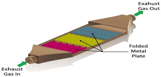
Figure 11.
Schematic diagram of a folded plate heat exchanger [141].
Lu et al. [143] studied a steam temperature drop in a heat exchanger and improved the overall TEG performance using a winglet vortex generator. Three sets of heat exchangers were tested in an experimental system. Their work suggested that the power output in a non-uniform vortex generator system is much higher than that of a smooth channel system and a uniform vortex generator system. However, the back pressure loss in both uniform and non-uniform heat exchangers is more significant than in the smooth channel heat exchanger, which is responsible for the reduction in the net power output. The result shows an improvement in the net power of 77.7% and 177.4% for the uniform and non-uniform heat exchanger systems, respectively, compared to the smooth channel system. A significant dependency function between the load resistance, power, and efficiency can be noticed in Figure 12, where the optimum load resistance plays a vital role in the system’s design value.
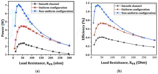
Figure 12.
Output power and efficiency with load resistance for smooth channel, uniform configuration, and non-uniform configuration [143]. (a) Power, (b) efficiency.
Ma et al. [144] conducted a numerical study to evaluate the effect of longitudinal vortex generators (LVGs) that are combined with flat-pin heat exchangers on the performance of a thermoelectric generator. Figure 13 plots the impact of the hot side’s inlet temperature on the net power and efficiency. The results indicate that complex three-dimensional vortices produced by downstream LVGs enhance heat transfer and the thermoelectric performance. The hot side’s inlet temperature and Reynolds number significantly enhance the net power and thermal efficiency, while the cold side’s temperature is less effective. The thermoelectric performance of a TEG is almost the same for both the case of boundary conditions for the constant temperature and a heat transfer coefficient that is applied at the cold side. Compared to a smooth channel, LVGs have a more significant pressure drop, especially at higher Reynolds numbers.
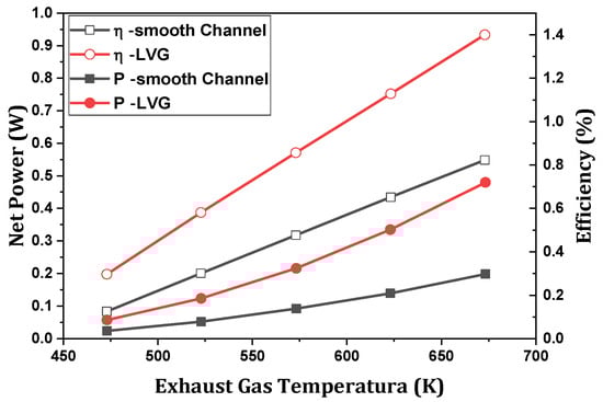
Figure 13.
Effect of hot side’s inlet temperature on net power and efficiency at Re = 487 and Tc = 363.15 K [144].
Figure 14 shows a schematic diagram of the inner structure of a hot heat exchanger. Wang et al. [145] conducted a comparative study between a rectangular fin heat exchanger and a dimpled surface heat exchanger (Figure 14). A CFD-based mathematical model of a Bismuth-telluride-based TEG was developed, and the results were validated by conducting a road test. They arranged the system into four sub-TEGs with four heat exchangers, and the exhaust gas was divided uniformly among them. Their study revealed that the temperature difference and output power increased slightly, but the pressure drop was significantly reduced for dimpled surfaces’ heat exchange compared to one with inserted fins. A comparative study of the performance of a different heat exchanger coupled with a TEG was carried out by Wang et al. [146]. These experimental and numerical studies show better thermo-hydraulic performance in a dimpled surface- or ribbed channel heat exchanger than in a flat surface heat exchanger. They suggested that the dimpled surface heat exchanger is preferable to the others, as it improves the TEG system’s performance and reduces the back pressure drop. Figure 15 displays the maximum power with the variation in the Reynolds number for different surface conditions in a heat exchanger. An increase in Re always increases the maximum power. Hong et al. [147] tried to maintain the uniformity of the longitudinal temperature distribution on the high-temperature side of a thermoelectric generator. They arranged for an aluminum-based heat exchanger to be placed in the central compartment of a three-compartment rectangular muffler. A theoretical model was established for the parabolic profile of the fins. They observed that temperature uniformity at different TEMs is essential to restrict power loss due to significant differences in voltage and current in different TEMs and a reduction in the module’s lifespan. The results demonstrated that the model can improve the temperature uniformity by up to 91.3% compared to a case with a uniform rectangular fin profile without altering the compactness. However, the temperature uniformity was due to the cost of reducing the heat absorption rate and power loss, but it was insignificant.

Figure 14.
Schematic diagram of inner structure of hot heat exchanger [145].
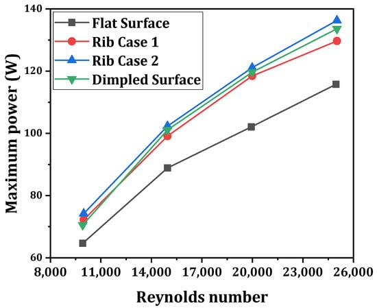
Figure 15.
Variation in maximum power with Reynolds number for different heat exchanger configurations [146].
6.3. Intermediate Fluid
In a conventional exhaust’s thermoelectric system, the primary components of the heat recovery unit, such as the exhaust’s heat exchanger, thermoelectric module, and cooling device unit, are usually arranged in a sandwich structure. Heat is transmitted from the exhaust gas to the module unit, where a part is converted into electrical energy, and the rest is dissipated in the cooling system. The performance of the TEG system is greatly influenced by the heat exchanger’s performance. When heat transfer is significantly low, the obtained output power in the heat recovery system is considerably lower. In that case, an intermediate fluid is incorporated into the system to enhance heat exchange.
Zhao et al. [148] designed a numerical simulation model of an IFTEG system, and results were recorded as depicted in Figure 16. This work reveals that the optimal module area of the IFTEG system is reduced by 74.2% compared with a conventional TEG system. The generation density and generation efficiency of the IFTEG system were 1254 Wm−2 and 4.51%, respectively, and this is 3.39 times and 1.43 times that of the conventional TEG, respectively, at a stipulated condition of 773 K of exhaust temperature and a mass flow rate of 20 gs−1. It can also be observed that there is an optimum exhaust heat exchange area for a fixed module area, and after that value, the variation in performance is insignificant. For the maximum output power, the corresponding generation density and conversion efficiency are independent of the variation in the exhaust’s heat exchange areas.
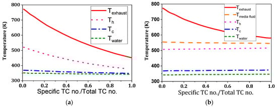
Figure 16.
Temperature distribution along the flow direction for (a) traditional TEG, (b) intermediate fluid TEG [148].
A comparative study [149] of the performance of a conventional TEG and IFTEG revealed that for an IFTEG, the enhancement in output power is 32.6%, and the reduction area in the thermoelectric optimum module is 73.8%. The results also show that for a fixed exhaust heat exchange area, the output power of the IFTEG reaches a maximum value for an optimum thermoelectric module area and then decreases with the increasing module area. It can also be observed that the peak output power and optimum module area increase rapidly with the increase in the exhaust’s heat exchange area, but these trends are gradually slowed down. In addition, the conversion efficiency is approximately 5.4% at the peak power and remains virtually unchanged after changing the exhaust’s heat exchange area. A relative study between air-cooling and water-cooling methods [150] suggested that the peak power output is slightly lower in the case of an IFTEG than a conventional TEG for an equal module area. The peak power output and the optimal module area are enhanced as the exhaust gas channel area increases. It can be noticed that the temperature distribution on the hot side is uniform, while on the cold side, it exhibits a significant variation under air-cooling methods. But under water cooling, it is uniform at both ends. The high efficiency of the IFTEG system can be obtained if the heat transfer coefficient is maintained at greater than 5000 Wm−2K−1 for both the boiling and the condensation. Figure 17 is a drawing of a TEG that is integrated with an intermediate fluid system.
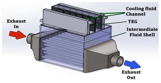
Figure 17.
Schematic diagram of a TEG integrated with intermediate fluid system [150].
Ge et al. [151] presented a mathematical model of a thermoelectric generator that is integrated with an intermediate fluid system. For an IFTEG, the thermal conductance is the crucial parameter that affects the performance. For the same exhaust heat exchange area, IFTEG gradually becomes less effective over the conventional TEG with the increase in the exhaust’s heat transfer coefficient. They also showed that the peak power of the IFTEG system increases with an increasing exhaust temperature and mass flow rate. The system’s efficiency improves with the increase in the exhaust temperature but was independent of the exhaust flow rate. In addition, the optimum module area of the IFTEG gradually increases with an increasing exhaust flow rate but remains substantially unaltered, even if the exhaust temperature changes. A superiority based on the power and efficiency of the IFTEG compared to the conventional TEG is highlighted in Figure 18.

Figure 18.
Power and efficiency as a function of total area for conventional TEG and IFTEG [151].
Zhang et al. [152] adopted a peak power deviation approach for optimizing the thermoelectric module area of an IFTEG system, where water was used as an intermediate fluid. The optimal module area for the maximum power output is a function of the exhaust’s heat exchanger area, temperature, and flow rate. The maximum power output and optimum module area escalate as the exhaust’s heat exchanger area and the exhaust’s flow rate increase. The exhaust’s peak power exhibits a corresponding increment with the rise in exhaust temperature, but the optimum module area remains unaltered. However, the power deviation is less impacted by the exhaust flow rate and temperature. From this work, it is also revealed that an optimally designed TEM area corresponds to a minimum peak power derivation. The stipulated range of input parameters allows for approaching the best operating condition.
6.4. Heat Pipes
Figure 19 depicts a heat pipe heat exchanger. The thermal resistance in the heat exchanger limits the heat transfer capacity and impacts the temperature difference across the TEM, reducing the TEG system’s output performance. Incorporating the heat pipes into the system overcomes this difficulty. The heat pipe is a passive heat exchange system with high thermal conductance. They are often called superconductors, as they can transfer large quantities of thermal energy with almost zero heat loss. In heat pipes, heat is transferred by boiling and subsequently condensing fluid in the confined space of the pipe. Heat energy is added to the fluid in the evaporator section of the heat pipe where the fluid boils. Then, the vapor flows toward the condenser section. Here, the vapor condenses on the surface of the capillary structure, thereby rejecting heat. A TEG is mounted on this section. Then, the condensed liquid returns to the evaporator section due to capillary action.
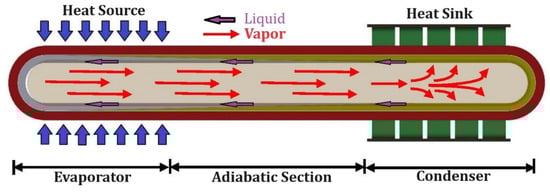
Figure 19.
Schematic diagram of a heat pipe.
Heat pipes provide advantages, including high heat conductivity, a constant operating temperature, compactness, and being light-weight. Moreover, heat pipes offer flexibility in their design, as they allow for the installation of the TEG away from the exhaust pipe’s surface. Over the years, many researchers have tried incorporating heat pipes into the TEG system to improve its performance. Jang et al. [153] presented a novel wickless loop heat pipe-based TEG system for convenience under the limited space of an exhaust pipe. The working fluid amount is a primary design parameter; thus, a smaller amount yields a better performance. The heat pipe-integrated TEG system is fully scalable for specific needs and can be installed in any location of automobile applications. Remeli et al. [154] demonstrated a theoretical model of a heat pipe assigned to a TEG system. Their simulated results highlight that the system with eight rows of TEGs can produce 10.39 W of electrical power and recover 1.36 kW of thermal energy from 2 kW heat input. Tang et al. [155] investigated the coupling heat transfer relationship between the heat pipes and TEGs experimentally. The experimental results exhibit that the heat pipe’s thermal efficiency is 95%, and the temperature drop between the evaporator and condenser is only up to 15 °C. They obtained a thermodynamic efficiency of 7.5% for the TEG, and for the heat pipe–TEG prototype, they obtained an efficiency of 6.2%.
A flat-plate heat pipe-assisted TEG model was constructed by Liu et al. [156], and results were recorded, as depicted in Figure 20. The hot air’s temperature does not affect the optimal number of thermoelectric couples. Still, it increases by reducing the thermal resistance of the heat pipe’s evaporator section and the cooling structure’s heat transfer coefficient. Remeli et al. [157] predicted a heat pipe-TEG system’s thermal and electrical performance using the effectiveness–NTU (number of heat transfer units) method. They considered bismuth telluride thermoelectric generators operating between two counterflow fluids. They found that an increase in the cold fluid’s velocity augments the system’s effectiveness. However, the output power obtained in the experimental study is lower than that of the numerical value, with a deviation of about 26%.
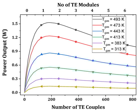
Figure 20.
The power output of heat pipe TEG at different inlet air temperatures [156].
Figure 21 illustrates a schematic diagram of a TEG integrated with an inclined heat pipe. Aranguren et al. [158] compared the effectiveness of two heat exchangers, an aluminum finned heat sink and a heat pipe. They took copper-based heat pipes and used water as the working fluid. They demonstrated that heat pipes are more effective than finned dissipators and produce 43% more net power than the finned system. Kim et al. [159] conducted an experimental study to investigate the thermal characteristics of a loop-type heat pipe under the influence of different working fluids. The heat pipe can transfer heat to any location to supply energy to the TEMs. Water performs best at a high heat flux in terms of power generation, while 0.05% TiO2 nanofluid is suitable in low-heat-flux conditions. Chi et al. [160] presented a thermoelectric power generator heat pipes with embedded fins. They investigated three heat pipe working fluids: water, ethanol, and nanofluid. The fluid filling rate, heat pipes’ orientation, and TEM size significantly affected TEG performance. The optimum values of the filling rate and inclination of the heat pipe differed for various fluids. The numerical results matched with experimental data. Orr et al. [161] studied the influence of heating under different heat pipe orientations on TEG performance. They suggested that a bottom-heating mode is the best option over top- and horizontal heating modes. They obtained a heat transfer rate of 1541 W, with a thermal efficiency of 2.46%. However, the system can cut fuel costs by around 1.57%. Figure 22 shows a strictly comparative investigation of power under different heat modes.
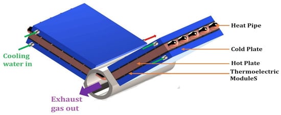
Figure 21.
Schematic diagram of TEG integrated with inclined heat pipe.
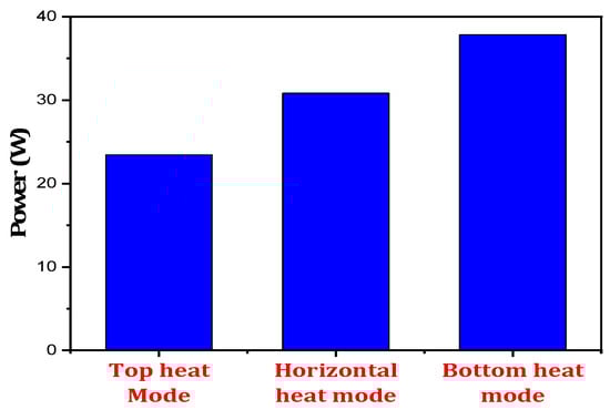
Figure 22.
Power output in different heating modes [161].
Li et al. [162] assessed the effect of different shapes and bending angles of cold-end micro heat pipe arrays on TEG performance. A nonlinear output performance was obtained under the influence of the bending angle. A bending angle of 130° corresponds to the best thermoelectric characteristics. At higher source temperatures, the power output augments with an increasing vertical height. Moreover, the optimum vertical height changes with the bending angles. Figure 23 demonstrates the output power as a function of temperature for different bending angles. There is an optimum bending angle for the maximum power.
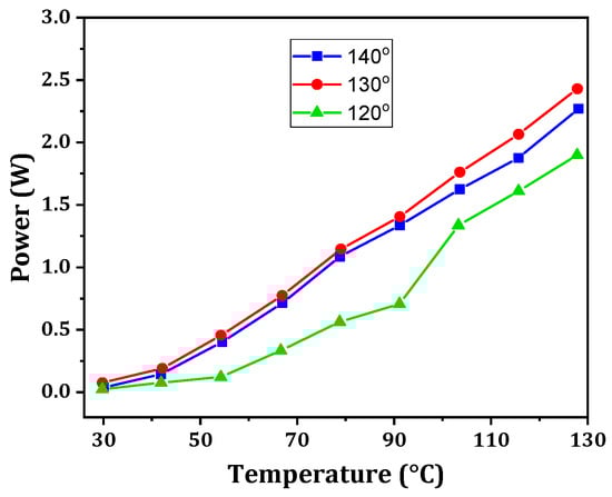
Figure 23.
Variation in power with temperature at different bending angles [162].
Brito et al. [163] developed a one-dimensional numerical model of a TEG integrated with variable conductance heat pipes (VCHPs), as shown in Figure 24, and the results were validated experimentally. A VCHP system enables the TEG to operate at an optimal temperature at part load. It provides cascading operation of the TEG without affecting the temperature level. The condenser’s output capacity is the limiting criterion for the low-heat pipe temperature, while it is the limiting criterion for the high-heat pipe temperature for the evaporator power.
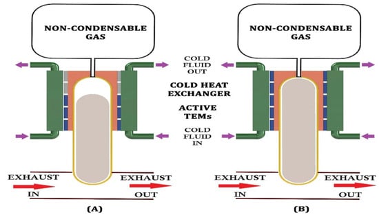
Figure 24.
Outline of a variable conductance heat pipe, (A) low thermal load, and (B) high thermal load [163].
6.5. Annular Thermoelectric Generator
A flat-plate heat exchanger TEG system requires modification of the exhaust pipe, which imposes repeated back pressure in the exhaust. An annular TEG system is easily connected to the exhaust pipe. Therefore, it is adjusted to any cylindrical pipe to recover and reuse the waste heat with minor modifications to the exhaust. For this reason, it produces a lesser amount of additional back pressure. Figure 25 represents a schematic diagram of the annular thermoelectric generator system.
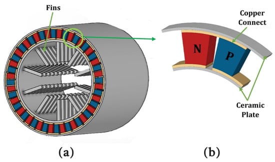
Figure 25.
Schematic diagram of (a) annular thermoelectric generator and (b) single thermocouple [164].
Yang et al. [164] optimized the system parameters and pin fin dimensions by utilizing the Taguchi method to maximize the output power. They demonstrated that the exhaust temperature is the most dominant factor for performance improvement, followed by the exhaust flow rate, fin length, fin diameter, and pin fin number, respectively. In addition, their results also show that the circular pin geometry outperforms the plate-shaped geometry. Du and Wu [165] tried to improve the conversion efficiency of a tubular thermoelectric generator. The system supplies 62.5% more power output than flat-plate thermoelectric generators. There is an optimum number of thermocouples that provide maximum power, as shown in Figure 26.
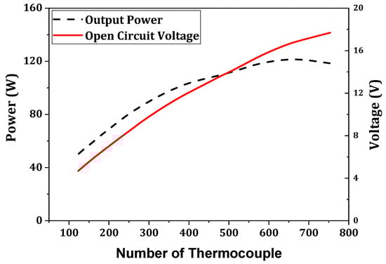
Figure 26.
Output power and open circuit voltage with thermocouple number [165].
Weng et al. [166] conducted a comparative study of a conventional annular thermoelectric generator and a counterpart with a variable-angle PN leg that were subjected to different boundary conditions. The results show that the output power depends on the variable cross-sections, boundary conditions, shape factor, radius ratio, and exponent coefficient. Yang et al. [167] proposed a numerical model of a concentric annular thermoelectric generator utilizing the finite element method. An optimum inner–outer diameter ratio of 0.94 for a heat exchanger that provides 65% enhanced power compared to a conventional annular TEG system was determined to obtain the maximum net power output. However, a diameter ratio range of 0.85–0.97 was required to achieve a peak efficiency of 4.5% or higher, with a maximum power deviation of 5.2%. Aljaghtham and Celik [168] demonstrated a unileg annular TEG system. Annular systems generate twice the output power compared to conventional ones. The annular configuration creates significant thermal stress. However, unileg annular TEG systems have low thermal stress without altering the output.
Yang et al. [169] presented an annular TEG that was integrated with a concentric narrow tube filled with heat transfer fluid (silicone polymer). The system’s net power is the maximum for the critical value of fluid flow rate, and the net power reduces below or over this value (shown in Figure 27). The HATEG system generates 15.2% more power and has a 19% smaller optimal module area than a conventional annular TEG system.
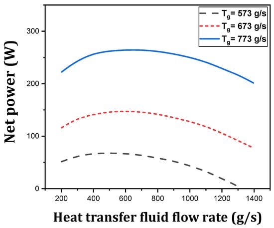
Figure 27.
Variation in net power with fluid flow rate at different exhaust inlet temperatures [169].
The performance improvements of TEGs for modified heat exchangers have been studied and are presented in Table 2. It can be demonstrated from this table that the modification can be made by adding fluid circulation channels, metal foams, plate fins, vortex generators, PCM, EG, etc. The performance and power improvements are clearly possible for the modification mentioned. Therefore, this study has a significant impact on the design of TEGs.
Table 2.
Performance improvement of a thermoelectric generator for modifying heat exchangers.
7. Structural Improvement of TE Leg for Automobile Systems
7.1. Leg Geometry Optimization
Shape and geometry optimization is a crucial strategy for improving thermoelectric performance. The operating conditions and the geometric structure of the TE leg both influence the output parameter. However, they improve performance and reduce material costs, highlighting the economic aspect of thermoelectric technology.
Wang et al. [180] enhanced the performance of a variable-leg TEG by the vital approach of minimizing the leg resistance. However, decreasing trends in thermal resistance reduce the conversion efficiency. Adding leg volume will improve the TEG performance for a fixed top and bottom area, while a fixed volume and shape variation is less effective. Luo et al. [181] presented a three-dimensional model for the performance analysis of a segmented TEG with variable leg geometry. They studied the thermoelectric parameters of different ratios of cross-sectional areas of p-legs and n-legs and different length ratios of segmented TEGs. They suggested that a trapezoidal n-leg should be avoided, while a trapezoidal p-leg should be used to maximize the TEG performance. Siddique et al. [182] mainly focused on nanomaterial-based trapezoidal-shaped leg geometry, and its performance was predicted by including different parasitic losses. The conversion efficiency of the nanomaterial-based trapezoidal-shaped leg TEG outperforms the traditional one by 8.74%. A good agreement between the analytical calculation and numerical results was highlighted. The conversion efficiency of the nanomaterial-based trapezoidal-shaped leg TEG is 8.74%, while that for the traditional one is 7.3%.
A comparative study of the performance of a rectangular leg, cone leg, and diamond leg, as illustrated in Figure 28, was carried out by Doraghi et al. [183]. They found that the rectangular leg shows a smoother temperature distribution, and the diamond-shaped configuration generates the maximum potential difference. They also determined that the diamond-shaped legs have lower thermal stresses than the others. A comparative study of the thermoelectric performance under five different leg geometries was carried out by Khalil et al. [184]. They varied the leg length and the cross-sectional area of the hot junction, while the leg volume was kept fixed for all five leg geometries. The rectangular leg is the best-performing model for a varied cross-sectional area model, with a 5.482% improvement. On the other hand, for the variable leg length model, the Y-leg shows a maximum efficiency of 5.338%, but the rectangular leg has the maximum power output. Figure 29 shows the performance characteristics of different leg geometries.

Figure 28.
Schematic diagram of leg geometry designs: (A) diamond shape, (B) cone shape [183].
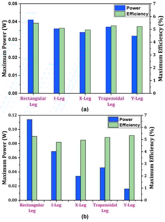
Figure 29.
Maximum power and maximum efficiency for different geometries for (a) varied cross-sectional area models and (b) variable leg length models [184].
Ibeagwu [185] investigated the performance of five different legs, including a rectangular leg, trapezoidal leg, Y-leg, I-leg, and X-leg (Figure 30). The X-shaped leg configuration is the most efficient over the others and shows the maximum temperature difference and highest power density. The maximum obtained conversion efficiency for the X-leg is 4.989%. Figure 31 shows the maximum efficiency for different leg geometries. However, the X-leg has the highest generated entropy density. Liu et al. [186] studied the performance of five leg geometries with a boundary condition of heat flux at the high-temperature end and convection at the colder end of the TEGs. The numerical results indicate that a configuration with a variable leg cross-section can enhance TEG performance. An hourglass-shaped TEG provides the maximum output power and conversion efficiency. Moreover, they proposed a shape factor of m and expressed the maximum power and maximum conversion efficiency in terms of m. An hourglass-shaped TEG has 69.62% more power and 70.96% more efficiency than a conventional cylindrical TRG.
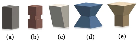
Figure 30.
Schematic diagram of leg geometric designs: (a) rectangular leg, (b) I-leg, (c) trapezoidal leg, (d) X-leg, and (e) Y-leg [185].

Figure 31.
Maximum conversion efficiency for different leg geometries [186].
Ge et al. [187] carried out an optimization study to maximize the performance of variable cross-section TEGs, as shown in Figure 32. They utilized the finite element method (FEM) along with the genetic algorithm (GA) and particle swarm optimization (PSO) algorithm for optimizing the geometry. The thermal and electrical resistance distribution significantly changed as the optimized TEG’s material volume remained constant. In addition, reducing the cross-sectional area of the optimized leg increased the temperature gradient and, thus, the performance.
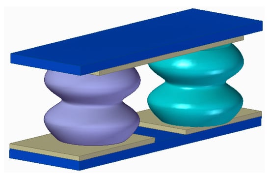
Figure 32.
Schematic diagram of a TEG model with hourglass-shaped legs [187].
7.2. Segmented Leg Geometry
Every TEG material performs best only within a particular range of temperatures. Over an extensive temperature range, they become unstable. A segmented thermoelectric generator (STEG) contains legs composed of several different TEG materials that can overcome this problem. Segmentation of the thermoelectric leg enables the leg section to operate in its best-performing temperature region. As a consequence, the overall power output and the conversion efficiency increase to a significant extent.
Shu et al. [188] presented a three-dimensional numerical model of a segmented TEG system that was integrated with a hexagonal heat exchanger. For a large temperature gradient, a segmented module is better than one with a single material (as shown in Figure 33). Also, the engine’s condition significantly impacts TEG performance. They also recommended installing fins where the temperature of a TEM is lower to improve the TEG performance. A segmented TEG improves the maximum power output by 30.8%. Zhao et al. [189] constructed a seven-layer segmented TEG consisting of four pairs of thermoelectric materials that were used on both legs. They analyzed the performance for every possible combination. They used a machine learning process to find the relationship between the output power and conversion efficiency for segmented leg materials with the help of a regression model. The optimal design generates a maximum power and maximum efficiency of 184.1 mW and 16.7%, respectively, representing an improvement of 86.14% and 31.79%, respectively. Liu et al. [190] constructed a three-dimensional model of a segmented TEG with asymmetrical legs with a variable cross-sectional area, drawn in Figure 34. They only focused on segmenting p-legs. They argued that more cross-sectional areas at the cold end are beneficial for the augmentation of the power output. They also presented an analytical model for determining the mean ZT value to obtain the optimum leg length ratio. In addition, they determined a relationship between the interface temperature and the ZT curve of the two materials.

Figure 33.
Schematic diagram of a segmented thermoelectric generator.

Figure 34.
Schematic diagram of a segmented TEG with asymmetrical and variable leg cross-sections.
A segmented TEG model was demonstrated by Sharma and Debbarma [191], and the effect of the base material insertion inside the p-leg towards the hot and cold surfaces was investigated. They obtained the maximum performance, and an optimum resistance ratio of unity was maintained. Karana and Sahoo [192] suggested a model of a segmented-leg TEG consisting of the traditional flat-pate p-leg, while the n-leg had a varying cross-sectional area. They introduced a geometric parameter, “a”, and showed that this strongly influences the thermoelectric performance of the segmented TEG. They also revealed that an asymmetrical and segmented configuration is more efficient than a single material configuration.
Ramos-Castañeda et al. [193] studied a TEG consisting of different leg geometries with three types of segmentation effects. They examined the performance of five different leg geometries with hollow and filled leg structures under the influence of different nanofluids. Figure 35 illustrates that the hollow structure with a triangular leg geometry generates the maximum power output and efficiency. TiO2 is the best-performing cooling fluid, as it over-performs by 17% compared to distilled water. The authors also proposed that 2n-1p segmentation is the best performing in terms of power and conversion efficiency. Zhang et al. [194] optimized the geometry of a segmented TEG with an irregularly variable cross-section design, utilizing a genetic algorithm. They determined that only segmentation or a variable cross-section design could achieve the optimum design for a fixed thermoelectric material volume. The optimized segmented irregularly variable cross-section TEG generated 51.71% and 7.57% more power than a conventional and only variable cross-section counterpart. Ge et al. [195] compiled the geometry of two segmented TEGs operating under parallel-flow and counter-flow arrangements. They adopted the genetic algorithm (GA) and FEM to obtain the optimal solution. The optimum result shows that segmented a TEG with a parallel flow configuration generates the maximum power and conversion efficiency. They also developed a hybrid model for simple manufacturing without sacrificing significant performance, and the best compromise results were obtained by the multiple criteria decision making (MCDM) technique. A triangular leg structure of a segmented TEG is depicted in Figure 36.
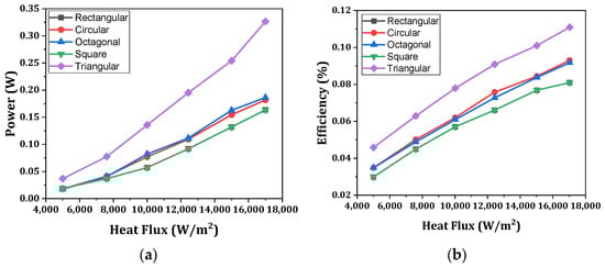
Figure 35.
Power output and efficiency as a function of heat flux for hollow leg [193]. (a) Power output, (b) efficiency.

Figure 36.
Schematic diagram of a segmented TEG with triangular leg structure [195].
Zhu et al. [196] optimized a one-dimensional model of a segmented TEG utilizing the GA. They studied four different geometric conditions: both legs segmented, p-leg segmented, n-leg segmented, and a traditional TEG. The performance characteristics are shown in Figure 37. They suggested a p-leg segmented TEG, as this led to only 1% less power than the segmented TEGs but facilitated higher reliability and a lower manufacturing cost. A reduction in contact resistance can significantly improve the output performance. Reducing the contact resistance from 150 Wcm2 to 250 Wcm2 per leg increased the conversion efficiency from 8.6% to 9.83%. The maximum power efficiency in a p-leg segmented TEG is 9.83%, a 25.4% improvement compared with a traditional one. Ge et al. [197] designed a segmented TEG system to obtain a maximum power output and minimum semiconductor volume by utilizing FEM and genetic algorithms. The best compromising solution for an optimized design was achieved by using TOPSIS. The result showed an optimum ratio of segmented leg material for achieving the maximum output.
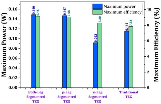
Figure 37.
Maximum power and maximum efficiency of different leg-segmented designs [196].
7.3. Multi-Stage TEG
Yin et al. [198] introduced a cascaded two-stage TEG system. Their results highlight that the design system can generate 13.5% more power than the conventional single-stage system under the same working conditions. The maximum conversion efficiency obtained was 18.38%. Maduabuchi et al. [199] presented a multi-stage TEG model consisting of a tapered leg geometry (trapezoidal and X-legs). They suggested that long thermoelectric legs increase the conversion efficiency, whereas shorter legs produce the highest power density. The optimized model improved the exergetic efficiency by 16.7% over a single-stage rectangular leg TEG. Kanimba et al. [200] conducted a comparative study of the performance of two-stage and three-stage cascaded TEG systems working under the same operating conditions. They demonstrated that the three-stage cascaded TEG generates 51W of power with an efficiency of 10.2%, which is 21% more than the two-stage system. Despite having 21% more power in the three-stage system, this system might not be preferable depending on several other parameters, including the material cost, design complexity, and robustness.
Aljaghtham and Celik [201] conducted a comparative study of multi-stage cascade unileg and unicouple designs, as shown in Figure 38. The simulated results show that the performance of a unileg design increased by ~75% compared with a unicouple design for both two-stage and three-stage TEG systems. The heat lost due to conduction and radiation was lower in the two-stage developed design and lowest in the three-stage developed design. Yang et al. [202] presented a two-stage TEG system with different integrated PCM embedding models. The design was developed with different PCM embedding arrangements, including at the heat source side, between two TEGs, and on the heat sink side. Compared to a single-stage TEG, the two-stage TEG achieved a 44.8% output power improvement and 6.9% higher conversion efficiency.

Figure 38.
Schematic diagram of two- and three-stage unileg and unicouple cascade TEGs [201].
Zhao et al. [203] presented a microscale two-stage TEG system, considering the end temperature of the TEM as a variable. Compared with a single-stage TEG, a two-stage TEG has much higher overall efficiency. The optimization of the TC numbers for maximum efficiency occurs at equal numbers of TC at both stages. The optimization resistance ratio decreases with an increasing input fuel power. Yin et al. [204] developed a multi-stage TEG model to study the effect of multi-parameter uncertainty on its performance. They adopted the Latin hypercube sampling method and Sobol’s methods for uncertainty analysis. Figure 39 illustrates that the power output and efficiency of the three-stage TEG increased by 36.40% and 34.47% compared with those of a single-stage TEG system, respectively. Uncertainty of working temperature is the most dominant factor, while uncertainty of resistance and leg cross-section ratios are less influential on TEG performance.
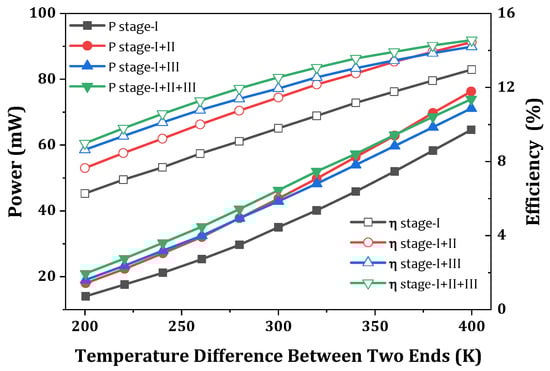
Figure 39.
Performance comparison of TEG with different numbers of stages under a constant temperature boundary with Tc = 300 K [204].
An attempt has been made to show the effect of TEM design on TEG performance in Table 3. A clear picture from this table can be identified of the effect of a variable cross-section leg geometry, segmented leg geometry, multi-stage, etc., on the performance. These design aspects play a significant role in improving the thermal performance of a TEG. A comparative output of these typical designs with respect to the basic model is also highlighted.
Table 3.
Effects of TEM design on TEG performances.
8. Actual Operating Condition
Luo et al. [210] presented a transient numerical model of an automobile TEG to characterize its dynamic behavior. They identified the response hysteresis of the system’s dynamic output in response to the change in input parameters. A small and short-term fluctuation in exhaust gas has a minor influence on the output power and voltage. Moreover, they are more stable with transient variation, but the scenario is the opposite regarding conversion efficiency. The dynamic performance depends on the vehicle’s speed and the change in exhaust heat [211]. Figure 40 shows comparative information on the steady and average power and efficiency of HWFET, NEDC, WLTP, and CLTC driving cycles. Compared with HWFET, NEDC, WLTP, and CLTC driving cycles, the TEG system exhibits the best performance under WLTP. Lan et al. [212] presented a dynamic TEG model considering counter-flow arrangements, and a TEG is installed upstream for an after-treatment system. The results show that optimizing the hot heat exchanger’s thermal contact conductance and the heat transfer coefficient enhances the average output power by 20%.
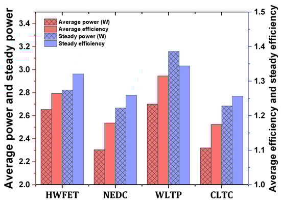
Figure 40.
Steady and average power and efficiency of HWFET, NEDC, WLTP, and CLTC driving cycles [211].
9. Conclusions
Waste heat is one of the most significant problems in the automobile sector. A thermoelectric generator, notwithstanding its low efficiency, can aid in gaining some percentage of efficiency and curtailing environmental pollution to some extent. Their main advantages are that they have zero emissions and no moving parts. Many investigations have been carried out in recent decades. This research highlights the advancement of existing work based on the thermoelectric potential, material synthesis, heat transfer mode, and the construction of geometries. The significant points discussed above can be summarized as follows:
- (a)
- The output performance of the TEG system depends on the material that is used, and the material performance depends on the ZT value. BiTe has a high ZT value at room temperature. SnSe is non-toxic and suitable for a medium to high temperature range. Most high-performing materials are used in the range of 500–1000 K, and most are expensive. Organic and inorganic composites are low-cost materials, but the ZT value is low, which makes the materials unsuitable for TEG applications. According to the literature, the highest ZT value is 3 for SnSe-based material. However, they are expensive to synthesize. The ZT value is as high as possible to achieve a higher conversion efficiency. However, no known material has a sufficient ZT value for reasonable performance. For example, for a temperature difference of 350 K and a ZT value of 10, obtaining a Carnot efficiency of ~30% is possible. Thus, we should emphasize research on high-performance and main material synthesis.
- (b)
- The convective heat transfer coefficient of exhaust gas is relatively low. A heat exchanger can enhance the heat absorption capability and improve temperature uniformity. On the other hand, it imposes additional weight and produces back pressure losses that reduce the engine’s combustion efficiency.
- (c)
- Metal foam and extended surfaces that are integrated into heat exchangers can significantly augment the convective heat transfer coefficient and thus improve the heat transfer rate. It was observed that the heat transfer effectiveness was enhanced by 283%, and the power output was doubled, when the foam filling rate was 75%. The integration of vortex generators enhanced the net power by 177.4%. A parabolic fin design improved the temperature uniformity of the TEG system by 91.3%. However, a significant temperature drop may occur along the flow direction. These additional features impose more back pressure losses. Much attention can be paid to selecting the type and dimension of the foam material and extended surface.
- (d)
- A phase change material used as an intermediate fluid promotes temperature uniformity in the system. It also allows the system to operate at a nearly constant temperature. The maximum improvement in power output is 32.6% compared to a conventional one, while the reduction in the thermoelectric optimum module area is 74.2%. The maximum conversion efficiency achieved is 5.4%, a 1.14-time improvement. However, it makes the system bulky and imposes additional weight.
- (e)
- A heat pipe is a super-thermal-conductive device that enhances the heat extraction capacity at both ends of the TEG. It allows the system to operate under a nearly constant temperature difference. It protects the device from high-temperature damage, provides the flexibility to overcome space limitations, and enables the system to accommodate far beyond the exhaust channel, where enough space is available. A VCHP permits the TEG system to operate at a constant temperature, even at part load. The heat pipe has low thermal resistance, and a slight temperature drop occurs between the evaporator and condenser at only 15 °C. Due to this, power output increases by 43%.
- (f)
- The leg shape and leg geometry greatly influence the thermal and electrical resistance, which further influence the overall performance. It also reduces the overall material cost. Despite this, it may lead to a compromise in mechanical strength. A nanomaterial-based trapezoidal-leg geometry has a maximum efficiency of 8.74%, which his 19.73% more than the traditional-leg TEG. Compared with a cylindrical-leg TEG, an hourglass-shaped TEG system has 69.62% greater output and 70.96% enhanced efficiency.
- (g)
- Segmentation and multi-staging lead to better power output and high-quality exhaust heat efficiency, enabling the TE material to operate in its best-performing temperature range. Increasing the number of segments and stages offers more power. However, these make the system more complex. Therefore, for the performance improvement, these changes should be made while selecting the number of segments and the different stages, considering other factors, including material cost, design complexity, and robustness. Segmented designs increase the power output by 30.8%. A system with segmented irregular legs increases the power by 51.71%. A seven-layer segmented TEG system achieves a maximum efficiency of 16.7%. On the other hand, compared to a single-stage TEG, the maximum power and maximum efficiency increase in a two-stage TEG by 44.8% and 6.9%, respectively. Meanwhile, these figures are 36.40% and 34.47% for a three-stage TEG. A unileg multi-stage cascaded TEG outperforms an uncoupled design by 75%.
10. Future Scope
For future works, efforts in this field of research can be focused on the following directions:
- 1.
- Material research may intensify to gain a higher ZT value with low costs.
- 2.
- Research can be carried out to improve the structural design of heat exchangers further to achieve lower thermal resistance and a high heat transfer coefficient. The catalytic converter can be modified as a heat exchanger by embedding metal foam and coating the metal form with a suitable catalyst.
- 3.
- On the cooling side of the TEM, the dissipated heat can be utilized to preheat the air that is used in engine combustion, thus improving the engine’s combustion efficiency.
- 4.
- At the cooling side of the TEM, the dissipated heat can be utilized to preheat the air that is used in the engine combustion, thus improving the engine’s combustion efficiency.
- 5.
- More work can be focused on optimizing the leg geometry, segmentation, and multi-staging.
TEG technology is expected to soon be vital in fueling economic measures. More efforts need to be focused on the research on TEGs across the globe, and OEMs may play a critical role in this aspect by implementing it in real-life applications.
Author Contributions
S.B.: Investigation, Conception/design of the research, Collection of data, Validation, Data analysis, Writing-original draft preparation. B.K.: Investigation, Conception/design of the research, Data interpretation, revision and final approval, Visualization, Supervision, Writing-Draft preparation, review, and editing. All authors have read and agreed to the published version of the manuscript.
Funding
This research received no external funding.
Data Availability Statement
The data presented in this study are available on reasonable request from the corresponding author.
Acknowledgments
The published works helped us prepare this review paper. All figures, graphs, and tables are newly constructed. The published documents provided data for preparing graphs and tables, and references are cited in the appropriate places. The authors acknowledge all contributors for their cooperation in completing this work.
Conflicts of Interest
The authors declare no conflict of interest.
Abbreviations
| BM | Ball milling |
| BST | Bismuth antimony telluride |
| CFD | Computational fluid dynamics |
| CLTC | China Light-duty vehicle Test Cycle |
| CSP | Cold-sintering process |
| DFT | Density Functional Theory |
| EG | Expanded graphite |
| FEM | Finite element method |
| GA | Genetic algorithm |
| HATEG | Heat transfer fluid in annular TEG |
| HP | Hot press |
| HPS | Hot-press sintering |
| HWFET | Highway Fuel Economy Test |
| ICE | Internal combustion engine |
| IFTEG | Intermediate fluid thermoelectric generator |
| LM | Levitation melting |
| LVG | Longitudinal vortex generator |
| M | Melting |
| MA | Mechanical alloying |
| Max | Maximum |
| MCDM | Multiple criteria decision making |
| MS | Melt-spinning |
| MWCNT | Multi-walled carbon nanotubes |
| NEDC | New European Driving Cycle |
| NTU | Number of Transfer Units |
| OEM | Original Equipment Manufacturer |
| P | Power |
| PCM | Phase change material |
| PPI | Pores per inch |
| PSO | Particle swarm optimization |
| RPH | Rapid Hot-pressing Sintering |
| SHS | Self-propagating High temperature Synthesis |
| SPS | Spark plasma sintering |
| STEG | Segmented thermoelectric generator |
| SUV | Sports utility vehicle |
| TC | Thermocouple |
| TE | Thermoelectric |
| TEG | Thermoelectric generator |
| TEM | Thermoelectric module |
| Temp | Temperature |
| TOPSIS | Technique for Order of Preference by Similarity to Ideal Solution |
| UT | Ultrasonic Treatment |
| VCHP | Variable conductance heat pipe |
| WLTP | Worldwide harmonized Light vehicles Test Procedure |
| ZT | Dimensionless figure of merit |
Nomenclature
| A | cross-sectional area (m2) |
| electric field vector (volt m−1) | |
| I | electric current (amp) |
| current density vector (amp m−2) | |
| k | thermal conductivity (Wm−1K−1) |
| thermal conductance (WK−1) | |
| L | length of thermocouple (m) |
| N | number of thermocouples |
| heat flux vector (Wm−2) | |
| volumetric heat generation rate (Wm−3) | |
| heat rate absorbed at the hot junction (W) | |
| heat rate evolved at the cold junction (W) | |
| electric resistivity (ohm m) | |
| electrical resistance (ohm) | |
| external load resistance (ohm) | |
| Re | Reynolds number |
| temperature (K) | |
| Arithmetic average temperature, (K) | |
| temperature at the hot junction (K) | |
| temperature at the cold junction (K) | |
| total voltage drops for N thermocouples (volt) | |
| net output power (W) | |
| coordinate starts from the hot junction to the cold junction (m) | |
| figure of merit (K−1) | |
| Greek Letters | |
| thermal or conversion efficiency | |
| Seebeck coefficient (volt K−1) | |
| Thomson coefficient (volt K−1) | |
| Subscripts | |
| max | extremum or maximum |
| n | n-type thermocouple |
| p | p-type thermocouple |
References
- Energy Institute. Statistical Review of World Energy 2023. Available online: https://www.energyinst.org/statistical-review (accessed on 13 July 2023).
- Oil Market Report—May 2023. Available online: https://www.iea.org/reports/oil-market-report-may-2023 (accessed on 26 November 2023).
- IEA. CO2 Emissions in 2022, IEA, Paris. 2023. Available online: https://www.iea.org/reports/co2-emissions-in-2022 (accessed on 13 July 2023).
- Hewawasam, L.S.; Jayasena, A.S.; Afnan, M.M.M.; Ranasinghe, R.A.C.P.; Wijewardane, M.A. Waste heat recovery from thermo-electric generators (TEGs). Energy Rep. 2020, 6, 474–479. [Google Scholar] [CrossRef]
- Mohamed, E.S. Development and performance analysis of a TEG system using exhaust recovery for a light diesel vehicle with assessment of fuel economy and emissions. Appl. Therm. Eng. 2019, 147, 661–674. [Google Scholar] [CrossRef]
- Vázquez, J.; Sanz-Bobi, M.A.; Palacios, R.; Arenas, A. State of the art of thermoelectric generators based on heat recovered from the exhaust gases of automobiles. In Proceedings of the 7th European Workshop on Thermoelectrics, Pamplona, Spain, 3–4 October 2002; p. 17. [Google Scholar]
- IB Physics. Available online: https://brettchoypd4.weebly.com/assessment-statements1.html (accessed on 3 July 2023).
- Ping, X.; Yang, F.; Zhang, H.; Xing, C.; Yu, M.; Wang, Y. Investigation and multi-objective optimization of vehicle engine-organic Rankine cycle (ORC) combined system in different driving conditions. Energy 2023, 263, 125672. [Google Scholar] [CrossRef]
- Ping, X.; Yang, F.; Zhang, H.; Xing, C.; Zhang, W.; Wang, Y.; Yao, B. Dynamic response assessment and multi-objective optimization of organic Rankine cycle (ORC) under vehicle driving cycle conditions. Energy 2023, 263, 125551. [Google Scholar] [CrossRef]
- Elmaihy, A.; Rashad, A.; Elweteedy, A.; Nessim, W. Energy and exergy analyses for organic Rankine cycle driven by cooling water of passenger car engine using sixteen working fluids. Energy Convers. Manag.: X 2023, 20, 100415. [Google Scholar] [CrossRef]
- Rêgo, A.T.; Hanriot, S.M.; Oliveira, A.F.; Brito, P.; Rêgo, T.F.U. Automotive exhaust gas flow control for an ammonia–water absorption refrigeration system. Appl. Therm. Eng. 2014, 64, 101–107. [Google Scholar] [CrossRef]
- Farzadi, R.; Bazargan, M. Experimental study of a diffusion absorption refrigeration cycle supplied by the exhaust waste heat of a sedan car at low engine speeds. Heat Mass Transf. 2020, 56, 1353–1363. [Google Scholar] [CrossRef]
- Alklaibi, A.M.; Lior, N. Waste heat utilization from internal combustion engines for power augmentation and refrigeration. Renew. Sustain. Energy Rev. 2021, 152, 111629. [Google Scholar] [CrossRef]
- Peng, Q.; Liu, R.; Zhou, G.; Zhao, X.; Dong, S.; Zhang, Z.; Zhang, H. Summary of Turbocharging as a Waste Heat Recovery System for a Variable Altitude Internal Combustion Engine. ACS Omega 2023, 8, 27932–27952. [Google Scholar] [CrossRef]
- Fu, J.; Liu, J.; Wang, Y.; Deng, B.; Yang, Y.; Feng, R.; Yang, J. A comparative study on various turbocharging approaches based on IC engine exhaust gas energy recovery. Appl. Energy 2014, 113, 248–257. [Google Scholar] [CrossRef]
- Teo, A.E.; Yahya, W.J.; Romagnoli, A.; Rajoo, S.; Noor, A.M. Effectiveness of series and parallel turbo compounding on turbocharged diesel engine. J. Mech. Eng. Sci. 2015, 8, 1448–1459. [Google Scholar] [CrossRef]
- Alwi, E.; Amin, B.; Afnison, W. Electric turbo compounding (ETC) as exhaust energy recovery system on vehicle. GEOMATE J. 2020, 19, 228–234. [Google Scholar]
- Güven, M.; Bedir, H.; Anlaş, G. Optimization and application of Stirling engine for waste heat recovery from a heavy-duty truck engine. Energy Convers. Manag. 2019, 180, 411–424. [Google Scholar] [CrossRef]
- Catapano, F.; Perozziello, C.; Vaglieco, B.M. Heat transfer of a Stirling engine for waste heat recovery application from internal combustion engines. Appl. Therm. Eng. 2021, 198, 117492. [Google Scholar] [CrossRef]
- Kodihal, K.; Sagar, A. Prototype Design of a Small Scale Thermionic Energy Generator for Waste Heat Recovery in Hybrid Electric Vehicle (No. 2019-28-0027); SAE Technical Paper 2019; SAE International: Warrendale, PA, USA, 2019. [Google Scholar] [CrossRef]
- Siddique, A.R.M.; Mahmud, S.; Van Heyst, B. A review of the state of the science on wearable thermoelectric power generators (TEGs) and their existing challenges. Renew. Sustain. Energy Rev. 2017, 73, 730–744. [Google Scholar] [CrossRef]
- Sanin-Villa, D. Recent Developments in Thermoelectric Generation: A Review. Sustainability 2022, 14, 16821. [Google Scholar] [CrossRef]
- Jouhara, H.; Żabnieńska-Góra, A.; Khordehgah, N.; Doraghi, Q.; Ahmad, L.; Norman, L.; Axcell, B.; Wrobel, L.; Dai, S. Thermoelectric generator (TEG) technologies and applications. Int. J. Thermofluids 2021, 9, 100063. [Google Scholar] [CrossRef]
- Zoui, M.A.; Bentouba, S.; Stocholm, J.G.; Bourouis, M. A Review on Thermoelectric Generators: Progress and Applications. Energies 2020, 13, 3606. [Google Scholar] [CrossRef]
- Yan, J.; Liao, X.; Yan, D.; Chen, Y. Review of micro thermoelectric generator. J. Microelectromechanical Syst. 2018, 27, 1–18. [Google Scholar] [CrossRef]
- Orr, B.; Akbarzadeh, A.; Mochizuki, M.; Singh, R. A review of car waste heat recovery systems utilising thermoelectric generators and heat pipes. Appl. Therm. Eng. 2016, 101, 490–495. [Google Scholar] [CrossRef]
- Zhang, L.; Lin, S.; Hua, T.; Huang, B.; Liu, S.; Tao, X. Fiber-based thermoelectric generators: Materials, device structures, fabrication, characterization, and applications. Adv. Energy Mater. 2018, 8, 1700524. [Google Scholar] [CrossRef]
- Muchuweni, E.; Mombeshora, E.T. Enhanced thermoelectric performance by single-walled carbon nanotube composites for thermoelectric generators: A review. Appl. Surf. Sci. Adv. 2023, 13, 100379. [Google Scholar] [CrossRef]
- Champier, D. Thermoelectric generators: A review of applications. Energy Convers. Manag. 2017, 140, 167–181. [Google Scholar] [CrossRef]
- Wright, D.A. Materials for direct-conversion thermoelectric generators. Metall. Rev. 1970, 15, 147–160. [Google Scholar] [CrossRef]
- Shen, Z.G.; Tian, L.L.; Liu, X. Automotive exhaust thermoelectric generators: Current status, challenges and future prospects. Energy Convers. Manag. 2019, 195, 1138–1173. [Google Scholar] [CrossRef]
- Crane, D.T.; LaGrandeur, J.W. Progress report on BSST-Led US department of energy automotive waste heat recovery program. J. Electron. Mater. 2010, 39, 2142–2148. [Google Scholar] [CrossRef]
- LaGrandeur, J.; Crane, D.; Hung, S.; Mazar, B.; Eder, A. Automotive waste heat conversion to electric power using skutterudite, TAGS, PbTe and BiTe. In Proceedings of the 2006 25th International Conference on Thermoelectrics, Vienna, Austria, 6–10 August 2006; IEEE: Piscataway, NJ, USA, 2006; pp. 343–348. [Google Scholar] [CrossRef]
- Espinosa, N.; Lazard, M.; Aixala, L.; Scherrer, H. Modeling a thermoelectric generator applied to diesel automotive heat recovery. J. Electron. Mater. 2010, 39, 1446–1455. [Google Scholar] [CrossRef]
- Mori, M.; Yamagami, T.; Sorazawa, M.; Miyabe, T.; Takahashi, S.; Haraguchi, T. Simulation of fuel economy effectiveness of exhaust heat recovery system using thermoelectric generator in a series hybrid. SAE Int. J. Mater. Manuf. 2011, 4, 1268–1276. [Google Scholar] [CrossRef]
- Hussain, Q.E.; Brigham, D.R.; Maranville, C.W. Thermoelectric exhaust heat recovery for hybrid vehicles. SAE Int. J. Engines 2009, 2, 1132–1142. [Google Scholar] [CrossRef]
- Ikoma, K.; Munekiyo, M.; Furuya, K.; Kobayashi, M.A.K.M.; Izumi, T.A.I.T.; Shinohara, K.A.S.K. Thermoelectric module and generator for gasoline engine vehicles. In Proceedings of the Seventeenth International Conference on Thermoelectrics. Proceedings ICT98 (Cat. No. 98TH8365), Nagoya, Japan, 24–28 May 1998; IEEE: Piscataway, NJ, USA, 1998; pp. 464–467. [Google Scholar] [CrossRef]
- Zulkepli, N.; Yunas, J.; Mohamed, M.A.; Hamzah, A.A. Review of Thermoelectric Generators at Low Operating Temperatures: Working Principles and Materials. Micromachines 2021, 12, 734. [Google Scholar] [CrossRef]
- Soleimani, Z.; Zoras, S.; Ceranic, B.; Cui, Y.; Shahzad, S. A comprehensive review on the output voltage/power of wearable thermoelectric generators concerning their geometry and thermoelectric materials. Nano Energy 2021, 89, 106325. [Google Scholar] [CrossRef]
- Zhu, B.; Su, X.; Shu, S.; Luo, Y.; Tan, X.Y.; Sun, J.; Sun, D.; Zhang, H.; Zhang, Q.; Suwardi, A.; et al. Cold-sintered Bi2Te3-based materials for engineering nanograined thermoelectrics. ACS Appl. Energy Mater. 2022, 5, 2002–2010. [Google Scholar] [CrossRef]
- Shi, Q.; Zhao, X.; Chen, Y.; Lin, L.; Ren, D.; Liu, B.; Zhou, C.; Ang, R. Cu2Te Incorporation-Induced High Average Thermoelectric Performance in p-Type Bi2Te3 Alloys. ACS Appl. Mater. Interfaces 2022, 14, 45582–45589. [Google Scholar] [CrossRef]
- Zhang, Q.; Yuan, M.; Pang, K.; Zhang, Y.; Wang, R.; Tan, X.; Wu, G.; Hu, H.; Wu, J.; Sun, P.; et al. High-Performance Industrial-Grade p-Type (Bi, Sb)2Te3 Thermoelectric Enabled by a Stepwise Optimization Strategy. Adv. Mater. 2023, 35, 2300338. [Google Scholar] [CrossRef] [PubMed]
- Shen, D.; Cheng, R.; Wang, W.; Li, H.; Chen, C.; Zhang, Q.; Chen, Y. Enhanced thermoelectric performance of p-type Bi2Si2Te6 enabled via synergistically optimizing carrier concentration and suppressing bipolar effect. Mater. Today Phys. 2023, 37, 101185. [Google Scholar] [CrossRef]
- Gayner, C.; Menezes, L.T.; Natanzon, Y.; Kauffmann, Y.; Kleinke, H.; Amouyal, Y. Development of Nanostructured Bi2Te3 with High Thermoelectric Performance by Scalable Synthesis and Microstructure Manipulations. ACS Appl. Mater. Interfaces 2023, 15, 13012–13024. [Google Scholar] [CrossRef] [PubMed]
- Shen, T.; Li, K.Y.; Chen, Z.J.; Wu, H.F.; Si, J.X. Enhanced Thermoelectric Performance of n-Type Polycrystalline SnSe via MoCl5 Doping. J. Electron. Mater. 2020, 49, 621–626. [Google Scholar] [CrossRef]
- Abbas, A.; Xu, Z.; Nisar, M.; Li, D.; Li, F.; Zheng, Z.; Liang, G.; Fan, P.; Chen, Y.-X. Achieving weak anisotropy in N-type I-doped SnSe polycrystalline thermoelectric materials. J. Eur. Ceram. Soc. 2022, 42, 7027–7035. [Google Scholar] [CrossRef]
- Zhang, S.; Zhu, C.; He, X.; Wang, J.; Luo, F.; Wang, J.; Liu, H.; Sun, Z. Enhanced thermoelectric performance of n-type polycrystalline SnSe via NdCl3 doping. J. Alloys Compd. 2022, 910, 164900. [Google Scholar] [CrossRef]
- Mao, X.-Y.; Shi, X.-L.; Zhai, L.-C.; Liu, W.-D.; Chen, Y.-X.; Gao, H.; Li, M.; Wang, D.-Z.; Wu, H.; Zheng, Z.-H.; et al. High thermoelectric and mechanical performance in the n-type polycrystalline SnSe incorporated with multi-walled carbon nanotubes. J. Mater. Sci. Technol. 2022, 114, 55–61. [Google Scholar] [CrossRef]
- Nisar, M.; Chen, Y.-X.; Qin, W.; Abbas, A.; Zheng, Z.; Fan, P.; Li, F. Effects of heavy bromine doping on the thermoelectric performance and dynamic stability of SnSe2 polycrystals. J. Alloys Compd. 2023, 959, 170566. [Google Scholar] [CrossRef]
- Li, D.; Tan, X.; Xu, J.; Liu, G.; Jin, M.; Shao, H.; Huang, H.; Zhang, J.; Jiang, J. Enhanced thermoelectric performance in n-type polycrystalline SnSe by PbBr2 doping. RSC Adv. 2017, 7, 17906–17912. [Google Scholar] [CrossRef]
- Mac, T.K.; Manh, D.H.; Nguyen, H.T.; Giang, T.T.H.; Lam, D.S.; Linh, D.C.; Pham, A.T.T.; Phan, B.T.; Thanh, T.D.; Duong, A.T. Synthesis and Thermoelectric Characterization of Sb-Doped Cu2Se by Mechanical Alloying and Solid-State Reaction. J. Electron. Mater. 2023, 53, 693–701. [Google Scholar] [CrossRef]
- Patel, S.R.; Chaki, S.H.; Solanki, M.B.; Kannaujiya, R.M.; Parekh, Z.R.; Khimani, A.J.; Deshpande, M.P. The impact of Ni and Zn doping on the thermal durability and thermoelectric variables of pristine CuSe nanoparticles. Mater. Adv. 2023, 4, 5238–5251. [Google Scholar] [CrossRef]
- Zhao, X.; Li, M.; Ma, R.; Zhang, Y.; Song, H. Effects of introducing MXene on thermoelectric properties of Cu2Se alloys. J. Alloys Compd. 2024, 971, 172787. [Google Scholar] [CrossRef]
- Rapaka, S.S.; Anwar, S.; Singh, J.; Anwar, S. Transport studies of two-step synthesized Cu2Se-Graphene nanocomposites. Phys. B: Condens. Matter 2023, 665, 415044. [Google Scholar] [CrossRef]
- Yang, D.; Zhang, D.; Ao, D.; Nisar, M.; Mansoor, A.; Chen, Y.; Li, F.; Ma, H.; Liang, G.; Zhang, X.; et al. High thermoelectric performance of aluminum-doped cuprous selenide thin films with exceptional flexibility for wearable applications. Nano Energy 2023, 117, 108930. [Google Scholar] [CrossRef]
- Bhat, P.C.; Anusha Ani, A.; Shanubhogue, U.D.; Poornesh, P.; Rao, A.; Chattopadhyay, S. Investigations on Bi Doped Cu2Se Prepared by Solid State Reaction Technique for Thermoelectric Applications. Energies 2023, 16, 3010. [Google Scholar] [CrossRef]
- Ahmed, A.J.; Hossain, M.S.A.; Islam, S.M.K.N.; Yun, F.; Yang, G.; Hossain, R.; Khan, A.; Na, J.; Eguchi, M.; Yamauchi, Y.; et al. Significant improvement in electrical conductivity and figure of merit of nanoarchitectured porous SrTiO3 by La doping optimization. ACS Appl. Mater. Interfaces 2020, 12, 28057–28064. [Google Scholar] [CrossRef]
- Zheng, Y.; Zhang, X.; Xie, W.; Ge, N.; Ren, Y.; Wei, X.; Dai, B. Thermoelectric performance enhancement for Ca3Co4O9 ceramics Co-doped with Ag and Tb. J. Electron. Mater. 2022, 51, 4938–4943. [Google Scholar] [CrossRef]
- Hira, U.; Ali, S.S.; Latif, S.; Pryds, N.; Sher, F. Improved high-temperature thermoelectric properties of dual-doped Ca3Co4O9. ACS Omega 2022, 7, 6579–6590. [Google Scholar] [CrossRef]
- Zhang, Z.; Zhang, C.; Liao, Q.; Qin, L.; Deng, D.; Liang, L. Optimizing electrical and thermal transport properties of Ca3Co4O9 based thermoelectric materials by Ag and Fe co-addition. Mater. Today Commun. 2022, 33, 104866. [Google Scholar] [CrossRef]
- Wu, H.; Shi, X.-L.; Liu, W.-D.; Gao, H.; Wang, D.-Z.; Yin, L.-C.; Liu, Q.; Chen, Z.-G. Ni doping and rational annealing boost thermoelectric performance of nanostructured double perovskite Pr1.8Sr0.2CoFeO6. Appl. Mater. Today 2022, 29, 101580. [Google Scholar] [CrossRef]
- Akram, R.; Khan, J.; Rafique, S.; Hussain, M.; Maqsood, A.; Naz, A.A. Enhanced thermoelectric properties of single-phase Na doped NaXCoO2 thermoelectric material. Mater. Lett. 2021, 300, 130180. [Google Scholar] [CrossRef]
- Van Du, N.; Binh, N.V.; Tran, M.T.; Tu, N.; Huy, P.T.; Rahman, J.U.; Shin, W.H.; Tuan, D.A.; Cho, J.Y.; Lee, S.; et al. Improved thermoelectric properties of Sb-doped Ti0. 5Zr0. 5NiSn alloy with refined structure induced by rapid synthesis processes. J. Alloys Compd. 2024, 970, 172528. [Google Scholar] [CrossRef]
- Tan, C.; Wang, H.; Yao, J.; Chen, T.; Wang, L.; Sun, Y.; Khan, M.; Wang, H.; Wang, C. Synchronously enhanced thermoelectric and mechanical properties of Ti doped NbFeSb based half-heusler alloys by carrier regulation and phonon engineering. J. Eur. Ceram. Soc. 2022, 42, 7010–7016. [Google Scholar] [CrossRef]
- Kahiu, J.N.; Shenoy, U.S.; Kihoi, S.K.; Kim, H.; Yi, S.; Bhat, D.K.; Lee, H.S. Optimized electronic performance in half-Heusler Ti-doped NbFeSb materials by stoichiometric tuning at the Fe and Sb sites. J. Alloys Compd. 2022, 891, 162033. [Google Scholar] [CrossRef]
- Wang, Q.; Xie, X.; Li, S.; Zhang, Z.; Li, X.; Yao, H.; Chen, C.; Cao, F.; Sui, J.; Liu, X.; et al. Enhanced thermoelectric performance in Ti(Fe, Co, Ni)Sb pseudo-ternary Half-Heusler alloys. J. Mater. 2021, 7, 756–765. [Google Scholar] [CrossRef]
- Zhang, X.; Li, S.; Zou, B.; Xu, P.; Song, Y.; Xu, B.; Wang, Y.; Tang, G.; Yang, S. Significant enhancement in thermoelectric properties of half-Heusler compound TiNiSn by grain boundary engineering. J. Alloys Compd. 2022, 901, 163686. [Google Scholar] [CrossRef]
- Sattar, M.A.; Javed, M.; Bouzieh, N.A.; Benkraouda, M.; Amrane, N. First-principles investigation on the novel half-Heusler VXTe (X=Cr, Mn, Fe, and Co) alloys for spintronic and thermoelectric applications. Mater. Sci. Semicond. Process. 2023, 155, 107233. [Google Scholar] [CrossRef]
- Liang, J.; Li, Y.; Yin, S.; Wan, C. Flexible organic-intercalated WSe2 hybrid: Electronic structure modification and thermoelectric performance optimization. Mater. Today Energy 2023, 36, 101355. [Google Scholar] [CrossRef]
- Qu, S.; Ming, C.; Qiu, P.; Xu, K.; Xu, Q.; Yao, Q.; Lu, P.; Zeng, H.; Shi, X.; Chen, L. High-performance n-type Ta4SiTe4/polyvinylidene fluoride (PVDF)/graphdiyne organic–inorganic flexible thermoelectric composites. Energy Environ. Sci. 2021, 14, 6586–6594. [Google Scholar] [CrossRef]
- Liang, J.; Li, Y.; Yin, S.; Wan, C. Organic-SnSe2 Hybrid Superlattice toward Synergistic Electrical Transport Optimization and Thermal Conductance Suppression. ACS Appl. Mater. Interfaces 2023, 15, 34956–34963. [Google Scholar] [CrossRef]
- Wang, Y.; Yao, Q.; Qu, S.; Chen, L. Thermoelectric Properties of n-type Poly (nickel 1,1,2,2-ethenetetrathiolate) Prepared by a New One-step Solvothermal Method. J. Wuhan Univ. Technol.-Mater. Sci. Ed. 2022, 37, 760–764. [Google Scholar] [CrossRef]
- Wang, B.; Zhao, H.; Zhang, B.; Wang, D.; Song, A.; Chen, C.; Yu, F.; Hu, W.; Yu, D.; Xu, B.; et al. Enhanced Thermoelectric Performance of n-Type PbTe via Carrier Concentration Optimization over a Broad Temperature Range. ACS Appl. Mater. Interfaces 2023, 15, 14424–14432. [Google Scholar] [CrossRef] [PubMed]
- Wang, S.; Chang, C.; Bai, S.; Qin, B.; Zhu, Y.; Zhan, S.; Zheng, J.; Tang, S.; Zhao, L.D. Fine Tuning of Defects Enables High Carrier Mobility and Enhanced Thermoelectric Performance of n-Type PbTe. Chem. Mater. 2023, 35, 755–763. [Google Scholar] [CrossRef] [PubMed]
- Lv, F.; Zhong, Y.; Zhao, X.; An, X.; Deng, Q.; Gan, L.; Lin, L.; Ang, R. Lead vacancy promotes sodium solubility to achieve ultra-high ZT in only ternary Pb1-xNaxTe. Small 2023, 19, 2301352. [Google Scholar] [CrossRef] [PubMed]
- Chen, P.; Wu, H.; Zhang, B.; Zhou, Z.; Zheng, S.; Dai, L.; Huo, Y.; Zhang, D.; Yan, Y.; Peng, K.; et al. Intrinsically low lattice thermal conductivity and anisotropic thermoelectric performance in In-doped GeSb2Te4 single crystals. Adv. Funct. Mater. 2023, 33, 2211281. [Google Scholar] [CrossRef]
- Si, R.; Zhang, Z.; Liu, C.; Peng, Y.; Bai, X.; Feng, B.; Chen, J.; Gao, J.; Miao, L. Decoupled electron and phonon transport in thermoelectric GeTe compounded with multi-waled carbon nanotubes. Mater. Today Phys. 2023, 34, 101081. [Google Scholar] [CrossRef]
- Yang, Z.; Tseng, Y.C.; Valiyaveettil, S.M.; Yuan, H.; Smith, E.; Chen, K.H.; Huang, Y.; Zou, T.; Kycia, J.; Mozharivskyj, Y. Optimized electronic properties and nano-structural features for securing high thermoelectric performance in doped GeTe. Dalton Trans. 2023, 52, 10689–10699. [Google Scholar] [CrossRef]
- Kim, S.; Kihoi, S.K.; Kim, H.; Kahiu, J.N.; Lee, H.S. Synergetic effect of Bi and Al co-doping in GeTe-based thermoelectric materials leading to optimized carrier concentration tuning and high ZT. J. Alloys Compd. 2024, 970, 172574. [Google Scholar] [CrossRef]
- Chueachot, R.; Nakhowong, R. Achieving thermoelectric performance of rGO/Bi0.5Sb1.5Te3/Cu2Se1–xTex composites through the scattering engineering strategy. J. Mater. 2023; In Press. [Google Scholar] [CrossRef]
- Ioannou, I.; Ioannou, P.S.; Kyratsi, T.; Giapintzakis, J. Effect of Starting Powder Particle Size on the Thermoelectric Properties of Hot-Pressed Bi0.3Sb1.7Te3 Alloys. Materials 2024, 17, 318. [Google Scholar] [CrossRef] [PubMed]
- Kumar, A.; Thoravat, S.; Jin, H.J.; Park, J.; Jin, H.; Rawat, P.; Rhyee, J.S. Hierarchical nano-/micro-architecture phonon scattering of p-type Bismuth Telluride bulk composites with Ag-TiO2 nano particles synthesized by fluidized bed spray coating method. J. Alloys Compd. 2024, 979, 173503. [Google Scholar] [CrossRef]
- Sun, Y.; Wu, H.; Dong, X.; Xie, L.; Liu, Z.; Liu, R.; Zhang, Q.; Cai, W.; Guo, F.; Sui, J. High Performance BiSbTe Alloy for Superior Thermoelectric Cooling. Adv. Funct. Mater. 2023, 33, 2301423. [Google Scholar] [CrossRef]
- Pang, K.; Yuan, M.; Zhang, Q.; Li, Y.; Zhang, Y.; Zhou, W.; Wu, G.; Tan, X.; Noudem, J.G.; Cui, C.; et al. High Performance Thermoelectric Power of Bi0.5Sb1.5Te3 Through Synergistic Cu2GeSe3 and Se Incorporations. Small 2023, 2306701. [Google Scholar] [CrossRef] [PubMed]
- Li, S.; Yin, L.; Liu, Y.; Wang, X.; Chen, C.; Zhang, Q. Rare earth element Ce enables high thermoelectric performance in n-type SnSe polycrystals. J. Mater. Sci. Technol. 2023, 143, 234–241. [Google Scholar] [CrossRef]
- Howells, G.; Mehraban, S.; McGettrick, J.; Lavery, N.; Carnie, M.J.; Burton, M. Rapid Printing of Pseudo-3D Printed SnSe Thermoelectric Generators Utilizing an Inorganic Binder. ACS Appl. Mater. Interfaces 2023, 15, 23068–23076. [Google Scholar] [CrossRef]
- Wang, Z.C.; Jiang, X.D.; Duan, Y.X.; Wang, X.; Ge, Z.H.; Cai, J.M.; Cai, X.M.; Tan, H.L. p-type Sn0.98Ag0.02Se with low thermal conductivity synthesized by hydrothermal method. J. Eur. Ceram. Soc. 2024, 44, 1636–1646. [Google Scholar] [CrossRef]
- Ma, J.; Chen, Y.; Li, W.; Luo, X. Predictability of thermoelectric figure of merit for the single crystal from first principles. Int. J. Heat Mass Transf. 2024, 221, 125063. [Google Scholar] [CrossRef]
- Wang, T.; Duan, X.; Zhang, H.; Ma, J.; Zhu, H.; Qian, X.; Yang, J.Y.; Liu, T.H.; Yang, R. Origins of three-dimensional charge and two-dimensional phonon transports in Pnma phase PbSnSe2 thermoelectric crystal. InfoMat 2023, 5, 12481. [Google Scholar] [CrossRef]
- Wang, Y.; Bai, S.; Shi, H.; Cao, Q.; Qin, B.; Zhao, L.D. Modulating structures to decouple thermoelectric transport leads to high performance in polycrystalline SnSe. J. Mater. Chem. A 2024, 12, 144–152. [Google Scholar] [CrossRef]
- Liu, D.; Wang, D.; Hong, T.; Wang, Z.; Wang, Y.; Qin, Y.; Su, L.; Yang, T.; Gao, X.; Ge, Z.; et al. Lattice plainification advances highly effective SnSe crystalline thermoelectrics. Science 2023, 380, 841–846. [Google Scholar] [CrossRef] [PubMed]
- Yang, X.; Shi, T.E.; Ma, X.Y.; Wang, Z.Y.; Wang, Y.; Wang, J.; Feng, J.; Ge, Z.H. High thermoelectric properties realized in polycrystalline (Ag, Ga) Co-doped SnSe via two-steps point defects modulation. J. Mater. Res. Technol. 2023, 27, 7606–7613. [Google Scholar] [CrossRef]
- Cao, W.; Wang, Z.; Miao, L.; Shi, J.; Xiong, R. Extremely anisotropic thermoelectric properties of SnSe under pressure. Energy Environ. Mater. 2023, 6, 12361. [Google Scholar] [CrossRef]
- Zhao, X.; Ning, S.; Qi, N.; Li, Y.; Dong, Y.; Zhang, H.; Liu, J.; Ye, B.; Chen, Z. Synergetic optimization of electrical and thermal transport properties by Cu vacancies and nanopores in Cu2Se. ACS Appl. Mater. Interfaces 2021, 13, 58936–58948. [Google Scholar] [CrossRef] [PubMed]
- Tie, J.; Xu, G.; Li, Y.; Fan, X.; Yang, Q.; Nan, B. The effect of SPS sintering temperatures on the structure, thermoelectric properties, and scattering mechanism of Cu2Se. J. Mater. Res. Technol. 2023, 27, 3506–3516. [Google Scholar] [CrossRef]
- Yu, J.; Hu, H.; Jiang, Y.; Zhuang, H.L.; Thong, H.C.; Su, B.; Li, J.W.; Han, Z.; Li, H.; Pei, J.; et al. Interface-Enhanced High-Temperature Thermoelectricity in Cu1.99Se/B4C Composites with Synergistically Improved Mechanical Strength. Adv. Energy Mater. 2024, 2303942. [Google Scholar] [CrossRef]
- Li, G.; Song, G.; Wang, N.; Wu, Y.; Du, H.; You, J.; Zhang, H. Enhancement of the thermoelectric properties in β-Cu2+ xSe/aC nano-multilayer films by heterogeneous interfaces. J. Alloys Compd. 2023, 930, 167432. [Google Scholar] [CrossRef]
- Long, Z.; Wang, Y.; Sun, X.; Li, Y.; Zeng, Z.; Zhang, L.; Chen, H. Band Engineering of the Second Phase to Reach High Thermoelectric Performance in Cu2Se-Based Composite Material. Adv. Mater. 2023, 35, 2210345. [Google Scholar] [CrossRef]
- Zhou, Z.; Huang, Y.; Wei, B.; Yang, Y.; Yu, D.; Zheng, Y.; He, D.; Zhang, W.; Zou, M.; Lan, J.L.; et al. Compositing effects for high thermoelectric performance of Cu2Se-based materials. Nat. Commun. 2023, 14, 2410. [Google Scholar] [CrossRef] [PubMed]
- Piyasin, P.; Palaporn, D.; Kurosaki, K.; Pinitsoontorn, S. High-performance thermoelectric properties of Cu2Se fabricated via cold sintering process. Solid State Sci. 2024, 149, 107448. [Google Scholar] [CrossRef]
- Rudradawong, C.; Khammuang, S.; Kotmool, K.; Bovornratanaraks, T.; Limsuwan, P.; Somdock, N.; Sakdanuphab, R.; Sakulkalavek, A. Enhanced thermoelectric properties of Cu2Se via Sb doping: An experimental and computational study. J. Eur. Ceram. Soc. 2023, 43, 401–406. [Google Scholar] [CrossRef]
- Wang, Z.; Zhao, H.; Luo, X.; Han, W.; Wang, H.; Meng, L.; She, X.; Quan, A.; Peng, Y.; Cai, G.; et al. Study on the Targeted Improvement Mechanism of the Carrier Concentration and Mobility of BiCuSeO Ceramics. Micromachines 2023, 14, 1757. [Google Scholar] [CrossRef] [PubMed]
- Zhou, Z.; Liu, R.; Yang, Y.; Zheng, Y.; Wei, B.; Zhang, W.; Zou, M.; Han, J.; Liu, Y.; Lan, J.; et al. Synergistic effects of CuI doping on enhancing thermoelectric performance for n-type Bi2O2Se fabricated by mechanical alloying. Scr. Mater. 2023, 225, 115163. [Google Scholar] [CrossRef]
- Du, X.; Zhang, G.; Guo, X.; Li, C.; Qi, G.; Yuan, Z. Synergistically optimizing thermoelectric performance of ZnO ceramics by interfacial band alignment and self-doping defects. J. Eur. Ceram. Soc. 2023, 43, 1978–1984. [Google Scholar] [CrossRef]
- Karim, A.M.M.T.; Islam, M.R.; Khatun, H.; Khan, M.K.R.; Rahman, M.M.; Shahjahan; Hossain, F.; Arif, E.M.H.; Nazrul-Islam, S.M.K. Ultrahigh Thermoelectric Performance of ZnO-CdO Thin Films. J. Electron. Mater. 2024, 53, 188–195. [Google Scholar] [CrossRef]
- He, Q.; Yang, D.; Xia, S.; Song, H. Ultra-low thermal conductivity and improved thermoelectric performance in La2O3-dispersed Bi2Sr2Co2Oy ceramics. Mater. Sci. Eng.: B 2024, 299, 116976. [Google Scholar] [CrossRef]
- Brlec, K.; Spooner, K.B.; Skelton, J.M.; Scanlon, D.O. Y2TiO5S2–a promising n-type oxysulphide for thermoelectric applications. J. Mater. Chem. A 2022, 10, 16813–16824. [Google Scholar] [CrossRef]
- Pallavi; Singh, C.P.; Kamlesh, P.K.; Gupta, R.; Verma, A.S. Thermoelectric performance of cadmium-based LiCdX (X= N, P, As, Sb and Bi)-filled tetrahedral semiconductors: Applications in green energy resources. Pramana 2023, 97, 162. [Google Scholar] [CrossRef]
- Ye, X.; Feng, Z.; Zhang, Y.; Zhao, G.; Singh, D.J. Low thermal conductivity and high thermoelectric performance via Cd underbonding in half-Heusler PCdNa. Phys. Rev. B 2022, 105, 104309. [Google Scholar] [CrossRef]
- Tan, C.; Wang, H.; Zhao, L.; Sun, Y.; Yao, J.; Zhai, J.; Wang, C.; Wang, H. Large mass field fluctuation and lattice anharmonicity effects promote thermoelectric and mechanical performances in NbFeSb half-Heusler alloys via Ti/Zr/Hf stepwise doping. J. Mater. Chem. A 2023, 11, 19036–19045. [Google Scholar] [CrossRef]
- Min, R.; Wang, Y.; Jiang, X.; Chen, R.; Li, M.; Kang, H.; Yang, X.; Chen, Z.; Guo, E.; Wang, T. ZrNiSn-based compounds with high thermoelectric performance and ultralow lattice thermal conductivity via introduction of multiscale scattering centers. J. Mater. 2024, 10, 200–209. [Google Scholar] [CrossRef]
- Bo, L.; Wang, W.; Zhu, J.; Li, C.; Zuo, M.; Zhao, D. Stepwise Alloying in Liquid-like Solid Solutions to Achieve Crystallographic Distortion for Regulating Thermoelectric Transport Behavior. ACS Appl. Mater. Interfaces 2023, 15, 54478–54487. [Google Scholar] [CrossRef] [PubMed]
- Singh, M.; Gautam, A.K.; Faraz, M.; Khare, N. Flexible, Freestanding Ternary Nanocomposite Thick Film of Polyaniline/WS2/CNTs for Efficient Thermoelectric Application. ACS Appl. Energy Mater. 2023, 7, 133–144. [Google Scholar] [CrossRef]
- Song, Y.; Dai, X.; Zou, Y.; Li, C.; Di, C.A.; Zhang, D.; Zhu, D. Boosting the Thermoelectric Performance of the Doped DPP-EDOT Conjugated Polymer by Incorporating an Ionic Additive. Small 2023, 19, 2300231. [Google Scholar] [CrossRef]
- Sherchenkov, A.; Borgardt, N.; Shtern, M.; Zaytseva, Y.; Shtern, Y.; Rogachev, M.; Sazonov, V.; Yakubov, A.; Pepelyaev, D. The role of nanostructuring strategies in PbTe on enhancing thermoelectric efficiency. Mater. Today Energy 2023, 37, 101416. [Google Scholar] [CrossRef]
- Zhang, M.; Cai, J.; Gao, F.; Zhang, Z.; Li, M.; Chen, Z.; Wang, Y.; Hu, D.; Tan, X.; Liu, G.; et al. Improved Thermoelectric Performance of p-Type PbTe by Entropy Engineering and Temperature-Dependent Precipitates. ACS Appl. Mater. Interfaces 2023, 16, 907–914. [Google Scholar] [CrossRef]
- Zhang, W.; Zhou, Z.; Yang, Y.; Zheng, Y.; Wei, B.; Lan, J.L.; Nan, C.W.; Lin, Y.H. Enhanced thermoelectric performance of n-type PbTe through introducing PbSe by a fast preparation method. Mater. Today Phys. 2023, 38, 101231. [Google Scholar] [CrossRef]
- Huang, Z.Y.; Wang, F.; Jung, C.; Zhang, S.; Zu, F.; Zhou, C.; Yu, Y. Decorated dislocations lead to dynamically optimized thermoelectric performance in N-type PbTe. Mater. Today Phys. 2023, 37, 101198. [Google Scholar] [CrossRef]
- Hu, Z.; Yu, H.; He, J.; Ran, Y.; Zeng, H.; Zhao, Y.; Yu, Z.; Tai, K. High-Performance Sb-Doped GeTe Thermoelectric Thin Film and Device. Acta Metall. Sin. 2023, 36, 1699–1708. [Google Scholar] [CrossRef]
- Jin, Y.; Ren, D.; Qiu, Y.; Zhao, L.D. Electrical and thermal transport properties of Ge1–xPbxCuySbyTeSe2y. Adv. Funct. Mater. 2023, 33, 2304512. [Google Scholar] [CrossRef]
- Zhang, T.; Qi, N.; Su, X.; Tang, X.; Chen, Z. Vacancy Suppression Induced Synergetic Optimization of Thermoelectric Performance in Sb-Doped GeTe Evidenced by Positron Annihilation Spectroscopy. ACS Appl. Mater. Interfaces 2023, 15, 40665–40675. [Google Scholar] [CrossRef] [PubMed]
- Wu, G.; Guo, Z.; Wang, R.; Tan, X.; Cui, C.; Sun, P.; Hu, H.; Wu, J.; Liu, G.; Jiang, J. Structural modulation and resonant level enable high thermoelectric performance of GeTe in the mid-to-low temperature range. J. Mater. Chem. A 2023, 11, 20497–20505. [Google Scholar] [CrossRef]
- Demir, M.E.; Dincer, I. Development and heat transfer analysis of a new heat recovery system with thermoelectric generator. Int. J. Heat Mass Transf. 2017, 108, 2002–2010. [Google Scholar] [CrossRef]
- Quan, R.; Liu, G.; Wang, C.; Zhou, W.; Huang, L.; Deng, Y. Performance investigation of an exhaust thermoelectric generator for military SUV application. Coatings 2018, 8, 45. [Google Scholar] [CrossRef]
- Asaduzzaman, M.; Ali, M.H.; Pratik, N.A.; Lubaba, N. Exhaust heat harvesting of automotive engine using thermoelectric generation technology. Energy Convers. Manag.: X 2023, 19, 100398. [Google Scholar] [CrossRef]
- Hong, T.D.; Nghiem, Q.T.; Mai, T.V.; Le, L.T. A numerical simulation and experimental study on thermal uniformity of heat exchanger in motorcycle thermoelectric generator unit. JP J. Heat Mass Transf. 2021, 22, 89–105. [Google Scholar] [CrossRef]
- Lu, H.; Wu, T.; Bai, S.; Xu, K.; Huang, Y.; Gao, W.; Yin, X.; Chen, L. Experiment on thermal uniformity and pressure drop of exhaust heat exchanger for automotive thermoelectric generator. Energy 2013, 54, 372–377. [Google Scholar] [CrossRef]
- Kumar, R.C.; Sonthalia, A.; Goel, R. Experimental study on waste heat recovery from an IC engine using thermoelectric technology. Therm. Sci. 2011, 15, 1011–1022. [Google Scholar] [CrossRef]
- Luo, D.; Wang, R.; Yu, W.; Sun, Z.; Meng, X. Modelling and simulation study of a converging thermoelectric generator for engine waste heat recovery. Appl. Therm. Eng. 2019, 153, 837–847. [Google Scholar] [CrossRef]
- Luo, D.; Wang, R.; Yu, W.; Zhou, W. A numerical study on the performance of a converging thermoelectric generator system used for waste heat recovery. Appl. Energy 2020, 270, 115181. [Google Scholar] [CrossRef]
- Buonomo, B.; Di Pasqua, A.; Manca, O.; Nardini, S. Numerical investigation on thermoelectric generators in an exhaust automotive line with aluminium foam. J. Phys.: Conf. Ser. 2020, 1599, 012014. [Google Scholar] [CrossRef]
- Li, Y.; Wang, S.; Zhao, Y.; Lu, C. Experimental study on the influence of porous foam metal filled in the core flow region on the performance of thermoelectric generators. Appl. Energy 2017, 207, 634–642. [Google Scholar] [CrossRef]
- Nithyanandam, K.; Mahajan, R.L. Evaluation of metal foam based thermoelectric generators for automobile waste heat recovery. Int. J. Heat Mass Transf. 2018, 122, 877–883. [Google Scholar] [CrossRef]
- Bai, W.; Yuan, X.; Liu, X. Numerical investigation on the performances of automotive thermoelectric generator employing metal foam. Appl. Therm. Eng. 2017, 124, 178–184. [Google Scholar] [CrossRef]
- Lu, C.; Wang, S.; Chen, C.; Li, Y. Effects of heat enhancement for exhaust heat exchanger on the performance of thermoelectric generator. Appl. Therm. Eng. 2015, 89, 270–279. [Google Scholar] [CrossRef]
- Li, Y.; Wang, S.; Zhao, Y.; Yue, L. Experimental study on the effect of core flow heat transfer enhancement on the performance of TEG. Energy Rep. 2022, 8, 575–580. [Google Scholar] [CrossRef]
- Wang, Y.; Wu, C.; Tang, Z.; Deng, Y.; Su, C. Optimization of fin distribution to improve the temperature uniformity of a heat exchanger in a thermoelectric generator. J. Electron. Mater. 2015, 44, 1724–1732. [Google Scholar] [CrossRef]
- Tang, Z.B.; Deng, Y.D.; Su, C.Q.; Yuan, X.H. Fluid analysis and improved structure of an ATEG heat exchanger based on computational fluid dynamics. J. Electron. Mater. 2015, 44, 1554–1561. [Google Scholar] [CrossRef]
- Borcuch, M.; Musiał; M.; Gumuła, S.; Sztekler, K.; Wojciechowski, K. Analysis of the fins geometry of a hot-side heat exchanger on the performance parameters of a thermoelectric generation system. Appl. Therm. Eng. 2017, 127, 1355–1363. [Google Scholar] [CrossRef]
- Wang, T.; Ma, S. Thermoelectric generator heat performance study about improved fin structures. Therm. Sci. 2018, 22, 101–112. [Google Scholar] [CrossRef]
- Su, C.Q.; Huang, C.; Deng, Y.D.; Wang, Y.P.; Chu, P.Q.; Zheng, S.J. Simulation and optimization of the heat exchanger for automotive exhaust-based thermoelectric generators. J. Electron. Mater. 2016, 45, 1464–1472. [Google Scholar] [CrossRef]
- Deng, Y.D.; Liu, X.; Chen, S.; Tong, N.Q. Thermal optimization of the heat exchanger in an automotive exhaust-based thermoelectric generator. J. Electron. Mater. 2013, 42, 1634–1640. [Google Scholar] [CrossRef]
- Lu, X.; Yu, X.; Qu, Z.; Wang, Q.; Ma, T. Experimental investigation on thermoelectric generator with non-uniform hot-side heat exchanger for waste heat recovery. Energy Convers. Manag. 2017, 150, 403–414. [Google Scholar] [CrossRef]
- Ma, T.; Lu, X.; Pandit, J.; Ekkad, S.V.; Huxtable, S.T.; Deshpande, S.; Wang, Q.W. Numerical study on thermoelectric–hydraulic performance of a thermoelectric power generator with a plate-fin heat exchanger with longitudinal vortex generators. Appl. Energy 2017, 185, 1343–1354. [Google Scholar] [CrossRef]
- Wang, Y.; Li, S.; Xie, X.; Deng, Y.; Liu, X.; Su, C. Performance evaluation of an automotive thermoelectric generator with inserted fins or dimpled-surface hot heat exchanger. Appl. Energy 2018, 218, 391–401. [Google Scholar] [CrossRef]
- Wang, Y.; Li, S.; Yang, X.; Deng, Y.; Su, C. Numerical and experimental investigation for heat transfer enhancement by dimpled surface heat exchanger in thermoelectric generator. J. Electron. Mater. 2016, 45, 1792–1802. [Google Scholar] [CrossRef]
- Hong, T.D.; Pham, M.Q.; Nghiem, Q.T.P. Thermal uniformity enhancement of the motorcycle exhaust thermoelectric generator—Theory model for predicting heat exchanger fin profile. Results Eng. 2023, 19, 101324. [Google Scholar] [CrossRef]
- Zhao, Y.; Wang, S.; Ge, M.; Liang, Z.; Liang, Y.; Li, Y. Performance analysis of automobile exhaust thermoelectric generator system with media fluid. Energy Convers. Manag. 2018, 171, 427–437. [Google Scholar] [CrossRef]
- Zhao, Y.; Wang, S.; Ge, M.; Liang, Z.; Liang, Y.; Li, Y. Performance investigation of an intermediate fluid thermoelectric generator for automobile exhaust waste heat recovery. Appl. Energy 2019, 239, 425–433. [Google Scholar] [CrossRef]
- Zhao, Y.; Fan, Y.; Ge, M.; Xie, L.; Li, Z.; Yan, X.; Wang, S. Thermoelectric performance of an exhaust waste heat recovery system based on intermediate fluid under different cooling methods. Case Stud. Therm. Eng. 2021, 23, 100811. [Google Scholar] [CrossRef]
- Ge, M.; Li, Z.; Zhao, Y.; Xie, L.; Wang, S. Effect of exhaust parameters on performance of intermediate fluid thermoelectric generator. Case Stud. Therm. Eng. 2021, 28, 101480. [Google Scholar] [CrossRef]
- Zhang, W.; Li, W.; Li, S.; Xie, L.; Ge, M.; Zhao, Y. Optimization design of an intermediate fluid thermoelectric generator for exhaust waste heat recovery. Processes 2023, 11, 1853. [Google Scholar] [CrossRef]
- Jang, J.-C.; Chi, R.-G.; Rhi, S.-H.; Lee, K.-B.; Hwang, H.-C.; Lee, J.-S.; Lee, W.-H. Heat pipe-assisted thermoelectric power generation technology for waste heat recovery. J. Electron. Mater. 2015, 44, 2039–2047. [Google Scholar] [CrossRef]
- Remeli, M.F.; Tan, L.; Date, A.; Singh, B.; Akbarzadeh, A. Simultaneous power generation and heat recovery using a heat pipe assisted thermoelectric generator system. Energy Convers. Manag. 2015, 91, 110–119. [Google Scholar] [CrossRef]
- Tang, S.; Wang, C.; Liu, X.; Su, G.; Tian, W.; Qiu, S.; Zhang, Q.; Liu, R.; Bai, S. Experimental investigation of a novel heat pipe thermoelectric generator for waste heat recovery and electricity generation. Int. J. Energy Res. 2020, 44, 7450–7463. [Google Scholar] [CrossRef]
- Liu, T.; Wang, T.; Luan, W.; Cao, Q. Optimal number of thermoelectric couples in a heat pipe assisted thermoelectric generator for waste heat recovery. J. Electron. Mater. 2017, 46, 3137–3144. [Google Scholar] [CrossRef]
- Remeli, M.F.; Singh, B.; Affandi, N.D.N.; Ding, L.C.; Date, A.; Akbarzadeh, A. investigation of counter-flow in a heat pipe–thermoelectric generator (HPTEG). J. Electron. Mater. 2017, 46, 3115–3123. [Google Scholar] [CrossRef]
- Aranguren, P.; Astrain, D.; Rodríguez, A.; Martínez, A. Experimental investigation of the applicability of a thermoelectric generator to recover waste heat from a combustion chamber. Appl. Energy 2015, 152, 121–130. [Google Scholar] [CrossRef]
- Kim, P.-J.; Rhi, S.-H.; Lee, K.-B.; Hwang, H.-C.; Lee, J.-S.; Jang, J.-C.; Lee, W.-H.; Lee, K.-W. Heat-pipe-associated localized thermoelectric power generation system. J. Electron. Mater. 2014, 43, 1613–1619. [Google Scholar] [CrossRef]
- Chi, R.-G.; Park, J.-C.; Rhi, S.-H.; Lee, K.-B. Study on heat pipe assisted thermoelectric power generation system from exhaust gas. Heat Mass Transf. 2017, 53, 3295–3304. [Google Scholar] [CrossRef]
- Orr, B.; Akbarzadeh, A.; Lappas, P. An exhaust heat recovery system utilising thermoelectric generators and heat pipes. Appl. Therm. Eng. 2017, 126, 1185–1190. [Google Scholar] [CrossRef]
- Li, T.; Fu, Y.; Dong, C.; Li, D.; Gu, H.; Ye, Y. Factors influencing the thermoelectric characteristics of a thermoelectric generator with cold-side micro heat pipe arrays. J. Power Sources 2023, 557, 232493. [Google Scholar] [CrossRef]
- Brito, F.P.; Martins, J.; Hançer, E.; Antunes, N.; Gonçalves, L.M. Thermoelectric exhaust heat recovery with heat pipe-based thermal control. J. Electron. Mater. 2015, 44, 1984–1997. [Google Scholar] [CrossRef]
- Yang, W.; Jin, C.; Zhu, W.; Li, Y.; Zhang, R.; Huang, L.; Xie, C.; Shi, Y. Taguchi optimization and thermoelectrical analysis of a pin fin annular thermoelectric generator for automotive waste heat recovery. Renew. Energy 2024, 220, 119628. [Google Scholar] [CrossRef]
- Du, K.W.; Wu, C.I. An Innovative Tubular Thermoelectric Generator (TTEG) for Enhanced Waste Heat Recovery in Industrial and Automotive Applications. Appl. Sci. 2024, 14, 685. [Google Scholar] [CrossRef]
- Weng, Z.; Liu, F.; Zhu, W.; Li, Y.; Xie, C.; Deng, J.; Huang, L. Performance improvement of variable-angle annular thermoelectric generators considering different boundary conditions. Appl. Energy 2022, 306, 118005. [Google Scholar] [CrossRef]
- Yang, W.; Zhu, W.; Li, Y.; Zhang, L.; Zhao, B.; Xie, C.; Yan, Y.; Huang, L. Annular thermoelectric generator performance optimization analysis based on concentric annular heat exchanger. Energy 2022, 239, 122127. [Google Scholar] [CrossRef]
- Aljaghtham, M.; Celik, E. Energy conversion and thermal reliability of thermoelectric materials in unileg annular configuration. Mater. Lett. 2021, 300, 130192. [Google Scholar] [CrossRef]
- Yang, W.; Zhu, W.; Du, B.; Wang, H.; Xu, L.; Xie, C.; Shi, Y. Power generation of annular thermoelectric generator with silicone polymer thermal conductive oil applied in automotive waste heat recovery. Energy 2023, 282, 128400. [Google Scholar] [CrossRef]
- Neska, M.; Mrozek, M.; Żurek-Mortka, M.; Majcher, A. Analysis of the Parameters of the Two-Sections Hot Side Heat Exchanger of the Module with Thermoelectric Generators. Energies 2021, 14, 5169. [Google Scholar] [CrossRef]
- Buonomo, B.; Cascetta, F.; di Pasqua, A.; Manca, O. Performance parameters enhancement of a thermoelectric generator by metal foam in exhaust automotive lines. Therm. Sci. Eng. Prog. 2023, 38, 101684. [Google Scholar] [CrossRef]
- Chen, W.H.; Chiou, Y.B.; Chein, R.Y.; Uan, J.Y.; Wang, X.D. Power generation of thermoelectric generator with plate fins for recovering low-temperature waste heat. Appl. Energy 2022, 306, 118012. [Google Scholar] [CrossRef]
- Luo, D.; Wu, Z.; Yan, Y.; Ji, D.; Cheng, Z.; Wang, R.; Li, Y.; Yang, X. Optimal design of a heat exchanger for automotive thermoelectric generator systems applied to a passenger car. Appl. Therm. Eng. 2023, 227, 120360. [Google Scholar] [CrossRef]
- Luo, D.; Yan, Y.; Li, Y.; Yang, X.; Chen, H. Exhaust channel optimization of the automobile thermoelectric generator to produce the highest net power. Energy 2023, 281, 128319. [Google Scholar] [CrossRef]
- Srivastava, K.; Sahoo, R.R. Effect of pitch and angle of attack on thermal performance of new envelope and delta vortex generators for TEG: An experimental and numerical approach. Int. J. Therm. Sci. 2024, 195, 108671. [Google Scholar] [CrossRef]
- Selvam, C.; Manikandan, S.; Krishna, N.V.; Lamba, R.; Kaushik, S.C.; Mahian, O. Enhanced thermal performance of a thermoelectric generator with phase change materials. Int. Commun. Heat Mass Transf. 2020, 114, 104561. [Google Scholar] [CrossRef]
- Tian, Y.; Liu, A.; Wang, J.; Zhou, Y.; Bao, C.; Xie, H.; Wu, Z.; Wang, Y. Optimized output electricity of thermoelectric generators by matching phase change material and thermoelectric material for intermittent heat sources. Energy 2021, 233, 121113. [Google Scholar] [CrossRef]
- Shi, Z.; Wang, G.; Liu, C.; Lv, Q.; Gong, B.; Zhang, Y.; Yan, Y. Optimizing the Transient Performance of Thermoelectric Generator with PCM by Taguchi Method. Energies 2023, 16, 805. [Google Scholar] [CrossRef]
- He, D.; Ou, D.; Gao, H.; Jiao, F. Performance evaluation of a thermoelectric generator-coupled composite phase change material for intermittent aerodynamic heat sources. Int. J. Energy Res. 2022, 46, 2698–2708. [Google Scholar] [CrossRef]
- Wang, P.; Wang, B.; Wang, K.; Gao, R.; Xi, L. An analytical model for performance prediction and optimization of thermoelectric generators with varied leg cross-sections. Int. J. Heat Mass Transf. 2021, 174, 121292. [Google Scholar] [CrossRef]
- Luo, Y.; Li, L.; Chen, Y.; Kim, C.N. Influence of geometric parameter and contact resistances on the thermal-electric behavior of a segmented TEG. Energy 2022, 254, 124487. [Google Scholar] [CrossRef]
- Siddique, A.R.M.; Kratz, F.; Mahmud, S.; Heyst, B.V. Energy conversion by nanomaterial-based trapezoidal-shaped leg of thermoelectric generator considering convection heat transfer effect. J. Energy Resour. Technol. 2019, 141, 082001. [Google Scholar] [CrossRef]
- Doraghi, Q.; Khordehgah, N.; Żabnieńska-Góra, A.; Ahmad, L.; Norman, L.; Ahmad, D.; Jouhara, H. Investigation and computational modelling of variable teg leg geometries. ChemEngineering 2021, 5, 45. [Google Scholar] [CrossRef]
- Khalil, A.; Elhassnaoui, A.; Yadir, S.; Abdellatif, O.; Errami, Y.; Sahnoun, S. Performance comparison of TEGs for diverse variable leg geometry with the same leg volume. Energy 2021, 224, 119967. [Google Scholar] [CrossRef]
- Ibeagwu, I.O. Modelling and comprehensive analysis of TEGs with diverse variable leg geometry. Energy 2019, 180, 90–106. [Google Scholar] [CrossRef]
- Liu, J.; Sun, Y.; Chen, G.; Zhai, P. Performance analysis of variable cross-section TEGs under constant heat flux conditions. Energies 2023, 16, 4473. [Google Scholar] [CrossRef]
- Ge, Y.; He, K.; Xiao, L.; Yuan, W.; Huang, S.M. Geometric optimization for the thermoelectric generator with variable cross-section legs by coupling finite element method and optimization algorithm. Renew. Energy 2022, 183, 294–303. [Google Scholar] [CrossRef]
- Shu, G.; Ma, X.; Tian, H.; Yang, H.; Chen, T.; Li, X. Configuration optimization of the segmented modules in an exhaust-based thermoelectric generator for engine waste heat recovery. Energy 2018, 160, 612–624. [Google Scholar] [CrossRef]
- Zhao, J.; Xu, W.; Kuang, Z.; Long, R.; Liu, Z.; Liu, W. Segmental material design in thermoelectric devices to boost heat-to-electricity performance. Energy Convers. Manag. 2021, 247, 114754. [Google Scholar] [CrossRef]
- Liu, H.-B.; Meng, J.-H.; Wang, X.-D.; Chen, W.-H. A new design of solar thermoelectric generator with combination of segmented materials and asymmetrical legs. Energy Convers. Manag. 2018, 175, 11–20. [Google Scholar] [CrossRef]
- Sharma, S.L.; Debbarma, A. Effect of p-leg material and resistance ratio on a segmented thermoelectric generator. Mater. Today: Proc. 2022, 66, 1023–1030. [Google Scholar] [CrossRef]
- Karana, D.R.; Sahoo, R.R. Influence of geometric parameter on the performance of a new asymmetrical and segmented thermoelectric generator. Energy 2019, 179, 90–99. [Google Scholar] [CrossRef]
- Ramos-Castañeda, C.F.; Olivares-Robles, M.A.; Olivares-Hernandez, A.E.; Hernandez-Gonzalez, L. Performance of a nanofluid-cooled segmented thermoelectric generator: Hollow/filled leg structures and segmentation effects. Processes 2023, 11, 1728. [Google Scholar] [CrossRef]
- Zhang, Y.-Q.; Sun, J.; Wang, G.-X.; Wang, T.-H. Advantage of a thermoelectric generator with hybridization of segmented materials and irregularly variable cross-section design. Energies 2022, 15, 2944. [Google Scholar] [CrossRef]
- Ge, Y.; Lin, Y.; He, Q.; Wang, W.; Chen, J.; Huang, S.M. Geometric optimization of segmented thermoelectric generators for waste heat recovery systems using genetic algorithm. Energy 2021, 233, 121220. [Google Scholar] [CrossRef]
- Zhu, L.; Li, H.; Chen, S.; Tian, X.; Kang, X.; Jiang, X.; Qiu, S. Optimization analysis of a segmented thermoelectric generator based on genetic algorithm. Renew. Energy 2020, 156, 710–718. [Google Scholar] [CrossRef]
- Ge, Y.; Liu, Z.; Sun, S.; Liu, W. Optimal design of a segmented thermoelectric generator based on three-dimensional numerical simulation and multi-objective genetic algorithm. Energy 2018, 147, 1060–1069. [Google Scholar] [CrossRef]
- Yin, T.; Li, Z.-M.; Peng, P.; Liu, W.; Shao, Y.-Y.; He, Z.-Z. Performance analysis of a novel two-stage automobile thermoelectric generator with the temperature-dependent materials. Appl. Therm. Eng. 2021, 195, 117249. [Google Scholar] [CrossRef]
- Maduabuchi, C.; Singh, S.; Ozoegwu, C.; Njoku, H.; Eke, M. The combined impacts of leg geometry configuration and multi-staging on the exergetic performance of thermoelectric modules in a solar thermoelectric generator. J. Energy Resour. Technol. 2022, 144, 041303. [Google Scholar] [CrossRef]
- Kanimba, E.; Pearson, M.; Sharp, J.; Stokes, D.; Priya, S.; Tian, Z. A modeling comparison between a two-stage and three-stage cascaded thermoelectric generator. J. Power Sources 2017, 365, 266–272. [Google Scholar] [CrossRef]
- Aljaghtham, M.; Celik, E. Design of cascade thermoelectric generation systems with improved thermal reliability. Energy 2022, 243, 123032. [Google Scholar] [CrossRef]
- Yang, H.; Li, M.; Wang, Z.; Ren, F.; Yang, Y.; Ma, B.; Zhu, Y. Performance optimization for a novel two-stage thermoelectric generator with different PCMs embedding modes. Energy 2023, 281, 128307. [Google Scholar] [CrossRef]
- Zhao, Z.; Zuo, Z.; Wang, W.; Liu, R.; Kuang, N. Performance optimization for a combustion-based micro thermoelectric generator with two-stage thermoelectric module. Appl. Therm. Eng. 2021, 198, 117464. [Google Scholar] [CrossRef]
- Yin, T.; Li, W.-T.; Li, K.; He, Z.-Z. Multi-parameter optimization and uncertainty analysis of multi-stage thermoelectric generator with temperature-dependent materials. Energy Rep. 2021, 7, 7212–7223. [Google Scholar] [CrossRef]
- Zhao, Y.; Li, W.; Zhao, X.; Wang, Y.; Luo, D.; Li, Y.; Ge, M. Energy and exergy analysis of a thermoelectric generator system for automotive exhaust waste heat recovery. Appl. Therm. Eng. 2024, 239, 122180. [Google Scholar] [CrossRef]
- Yin, T.; Ren, D.; Ma, X.; Wei, Y.; Gao, Q.; Han, X. Optimal Design and Multi-Parameter Sensitivity Analysis of a Segmented Thermoelectric Generator. Processes 2023, 11, 3352. [Google Scholar] [CrossRef]
- Wang, X.; Qi, J.; Deng, W.; Li, G.; Gao, X.; He, L.; Zhang, S. An optimized design approach concerning thermoelectric generators with frustum-shaped legs based on three-dimensional multiphysics model. Energy 2021, 233, 120810. [Google Scholar] [CrossRef]
- Cheng, K.; Qin, J.; Jiang, Y.; Zhang, S.; Bao, W. Performance comparison of single-and multi-stage onboard thermoelectric generators and stage number optimization at a large temperature difference. Appl. Therm. Eng. 2018, 141, 456–466. [Google Scholar] [CrossRef]
- Cheng, K.; Qin, J.; Jiang, Y.; Lv, C.; Zhang, S.; Bao, W. Performance assessment of multi-stage thermoelectric generators on hypersonic vehicles at a large temperature difference. Appl. Therm. Eng. 2018, 130, 1598–1609. [Google Scholar] [CrossRef]
- Luo, D.; Wang, R.; Yan, Y.; Yu, W.; Zhou, W. Transient numerical modelling of a thermoelectric generator system used for automotive exhaust waste heat recovery. Appl. Energy 2021, 297, 117151. [Google Scholar] [CrossRef]
- Luo, D.; Yan, Y.; Li, Y.; Chen, W.-H.; Yang, X.; Wang, X.; Cao, B. Dynamic behaviour of automobile thermoelectric waste heat recovery under different driving cycles. Appl. Therm. Eng. 2023, 232, 121039. [Google Scholar] [CrossRef]
- Lan, S.; Yang, Z.; Chen, R.; Stobart, R. A dynamic model for thermoelectric generator applied to vehicle waste heat recovery. Appl. Energy 2018, 210, 327–338. [Google Scholar] [CrossRef]
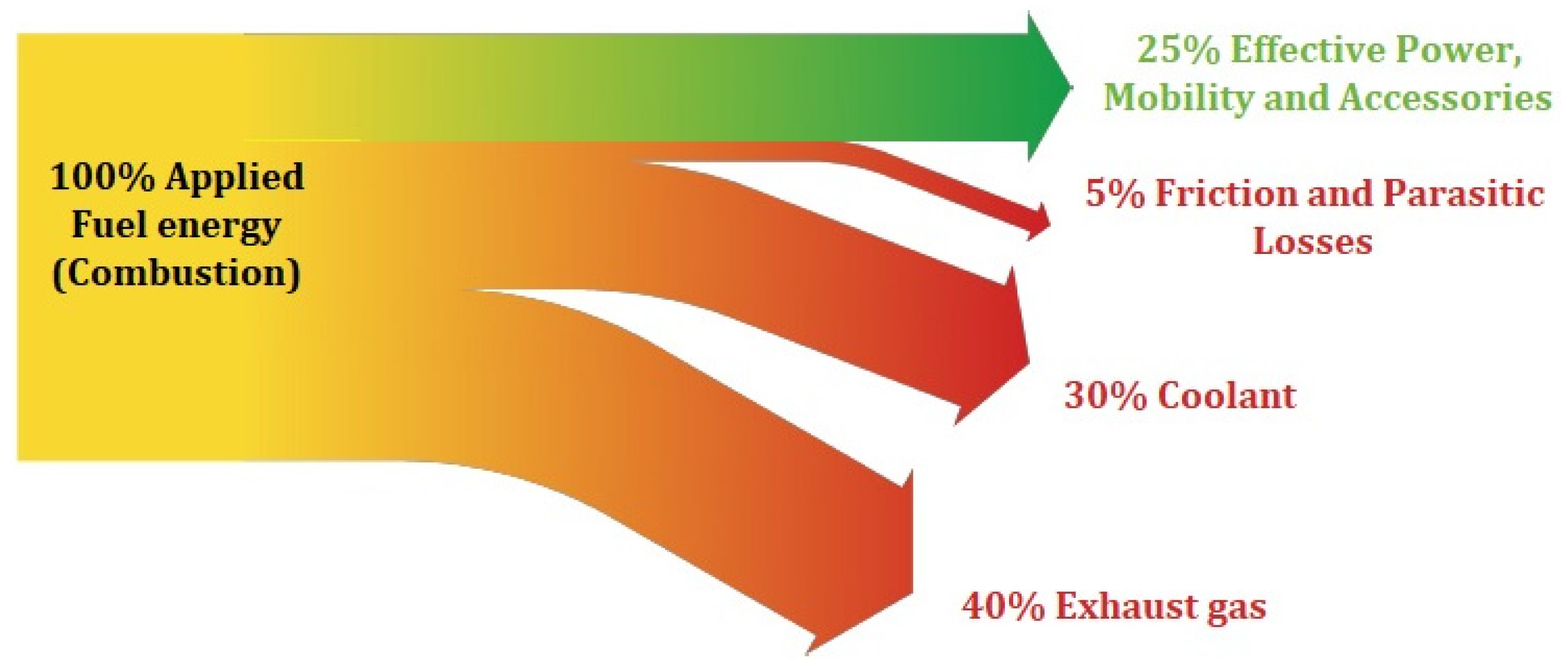
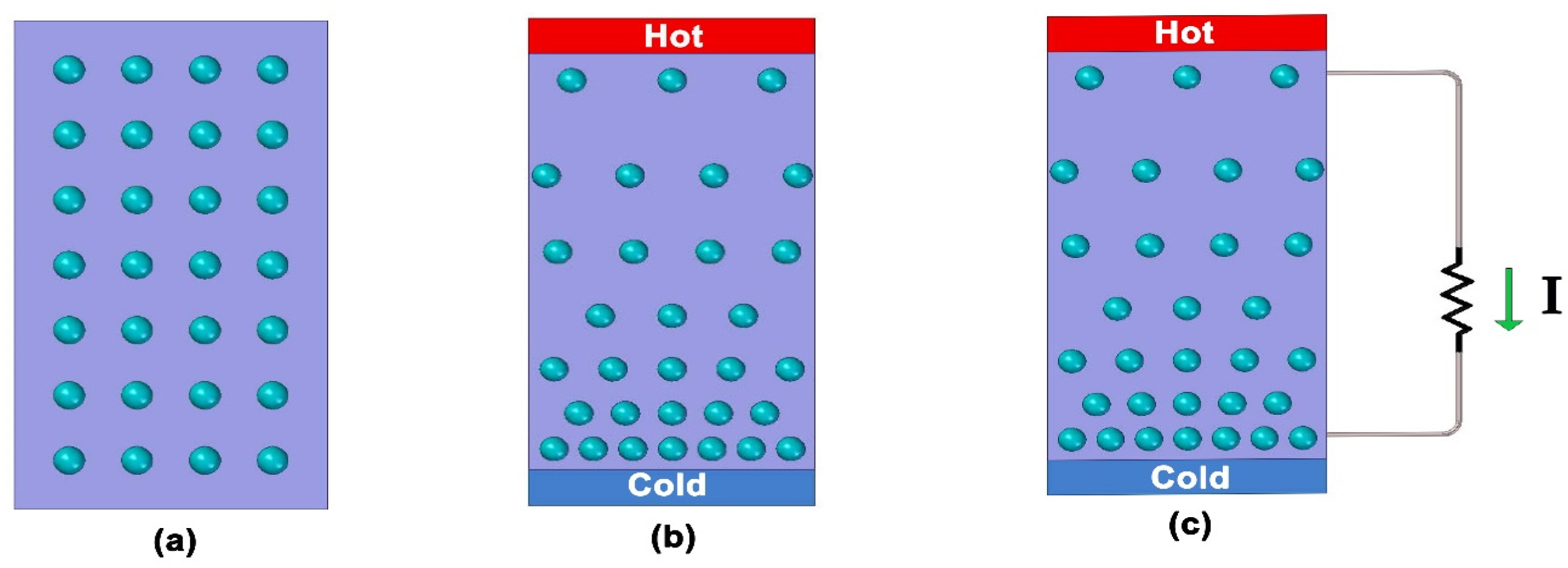
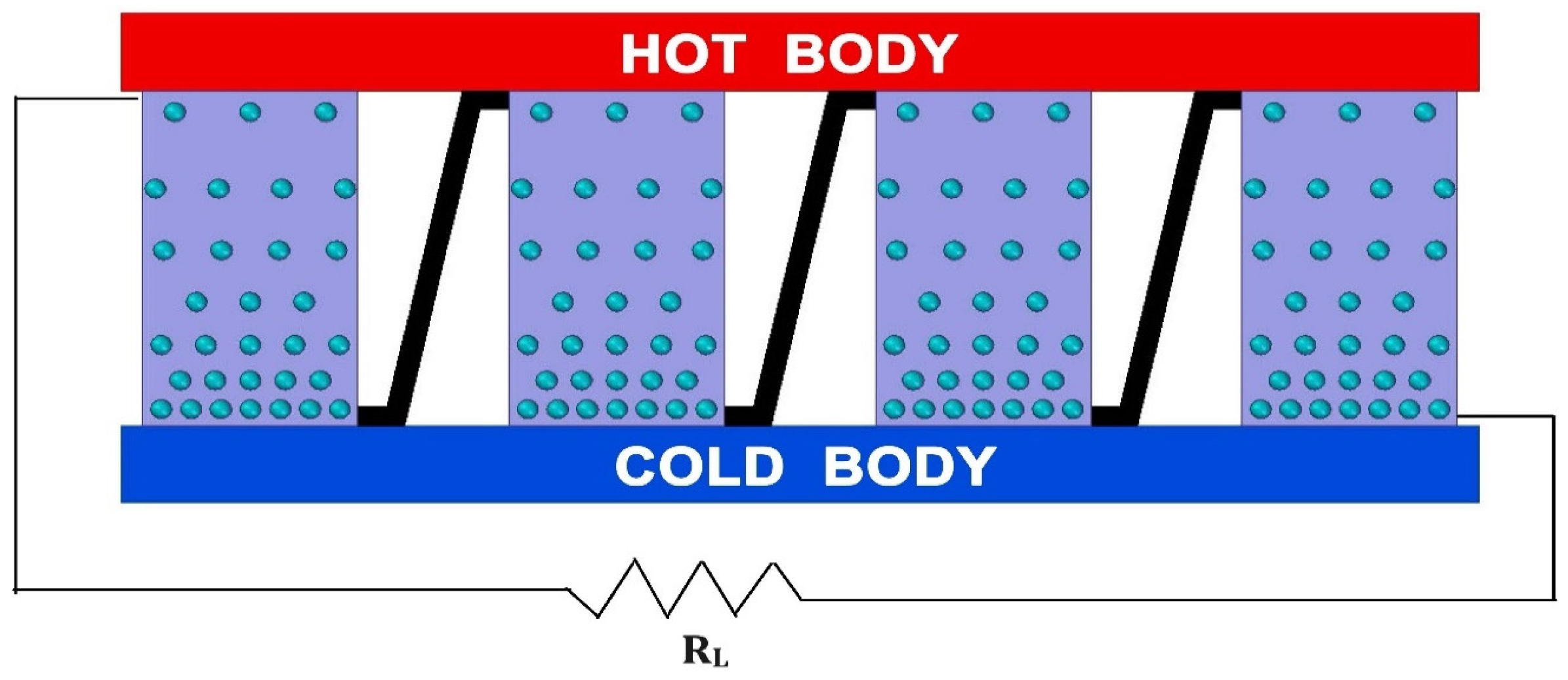

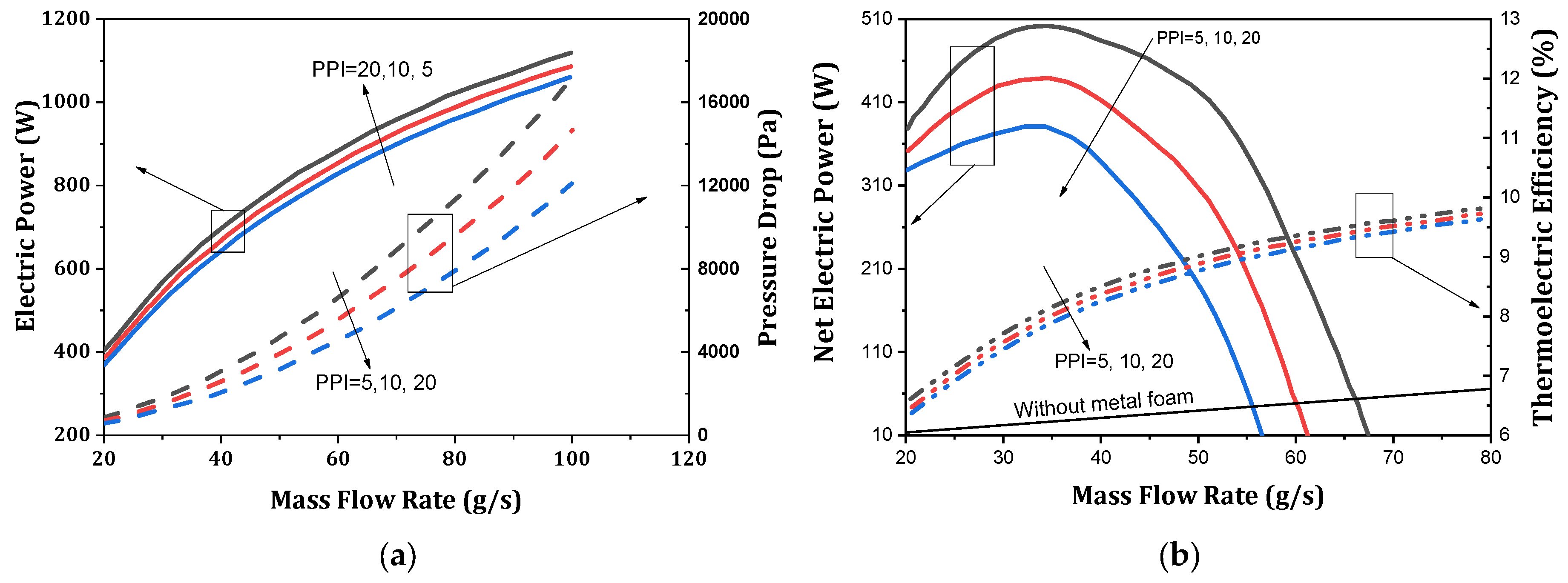
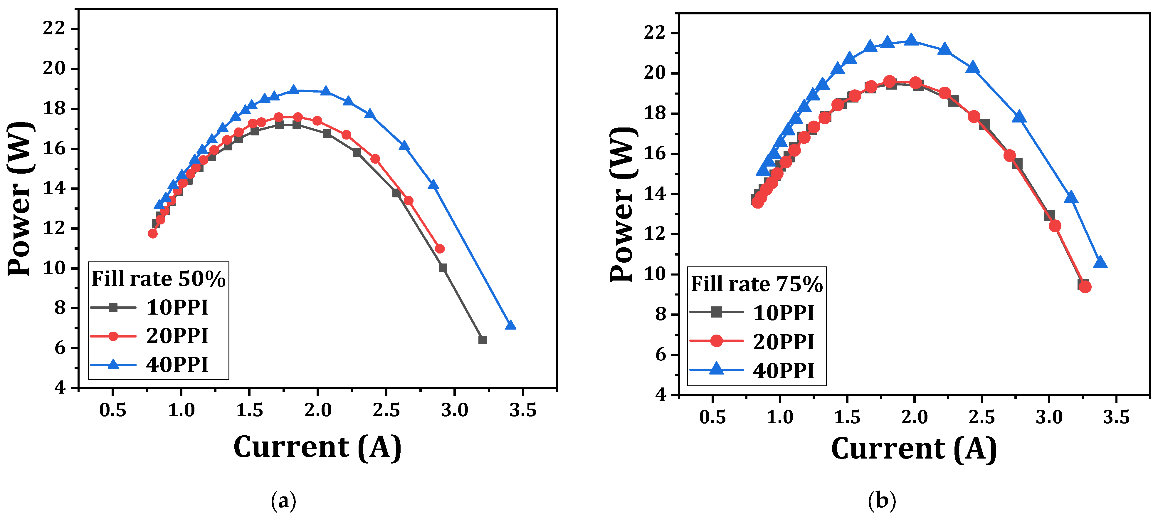


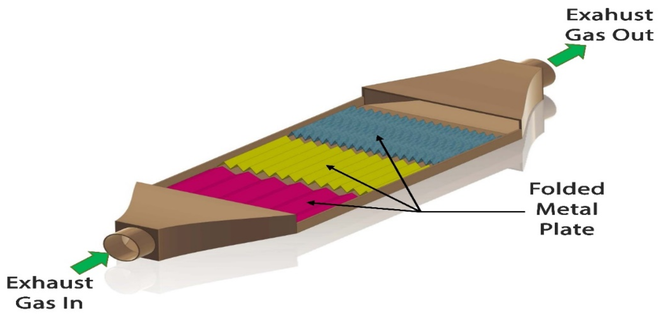
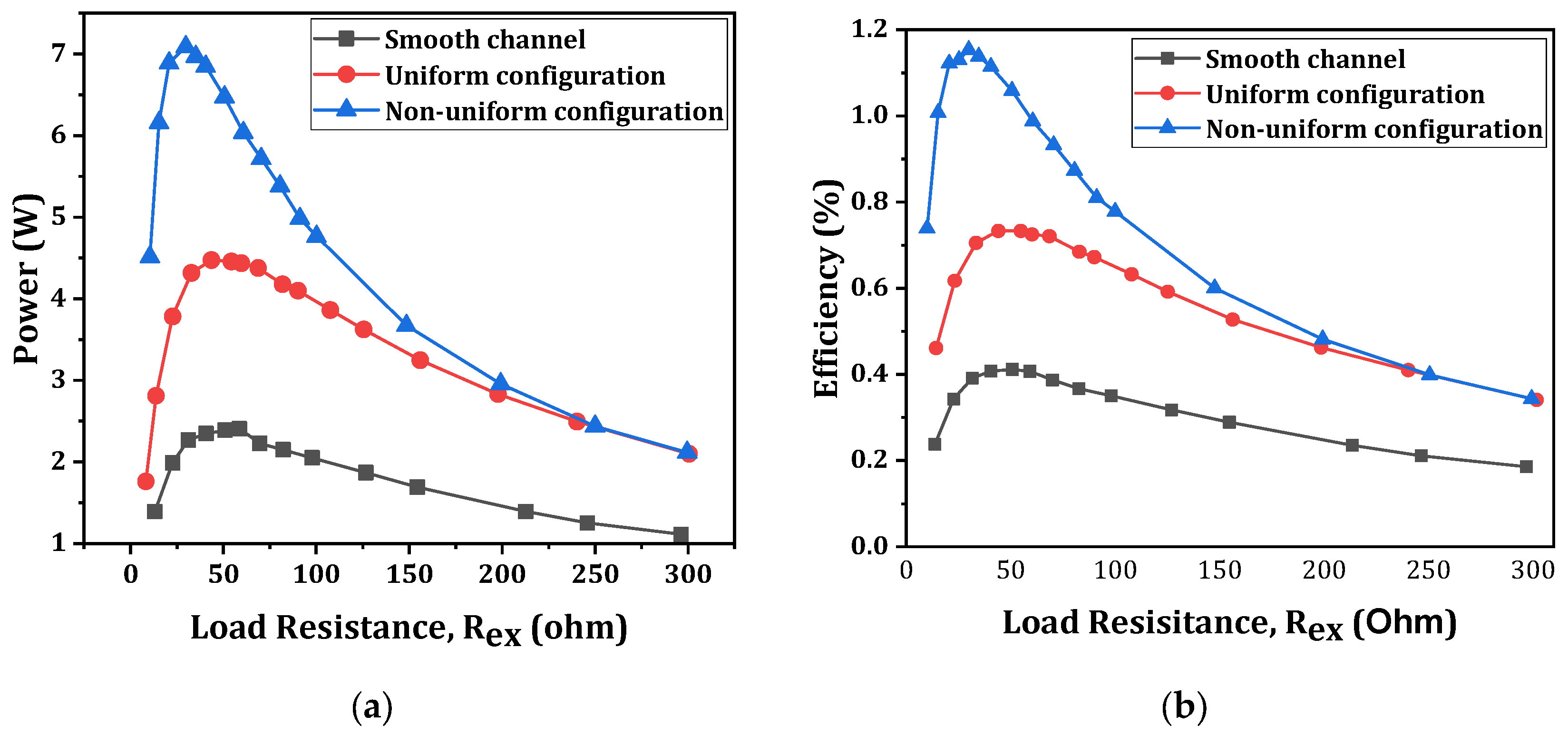
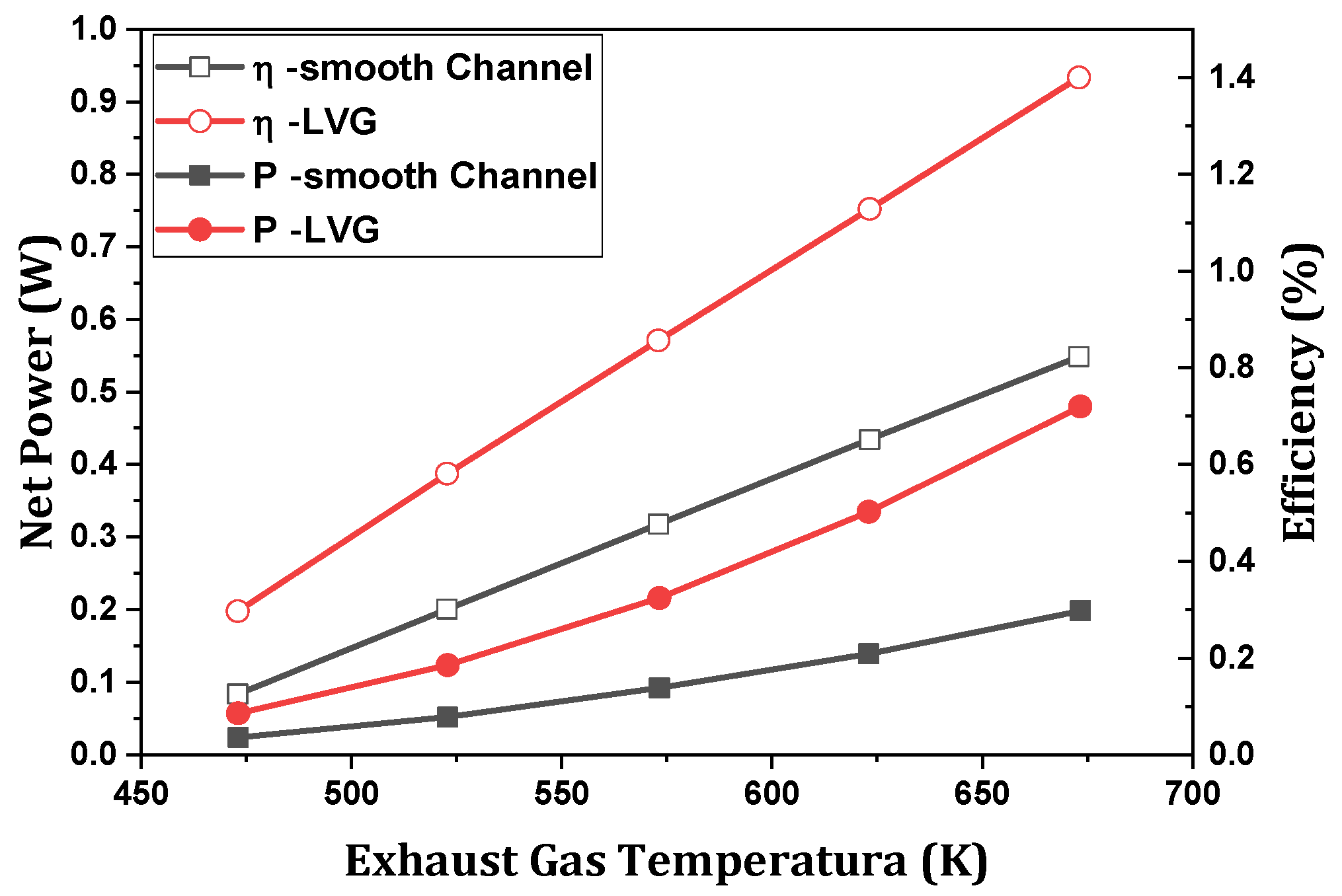
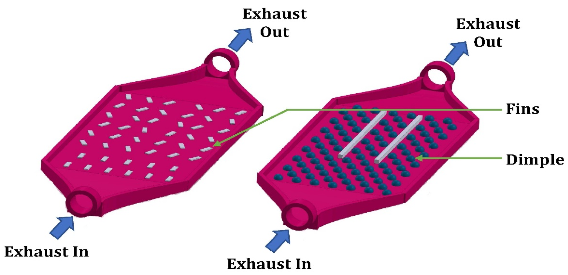
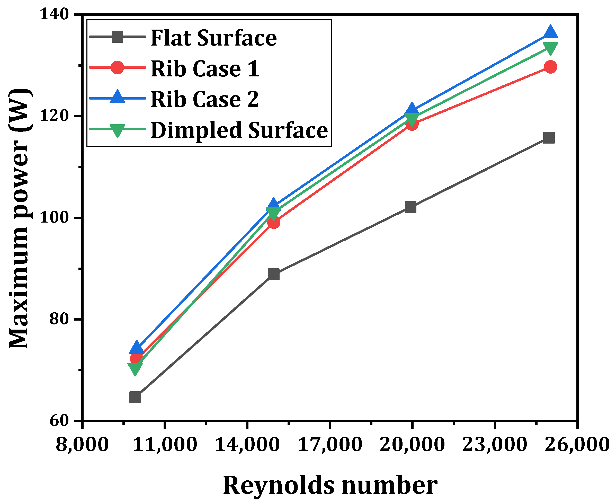
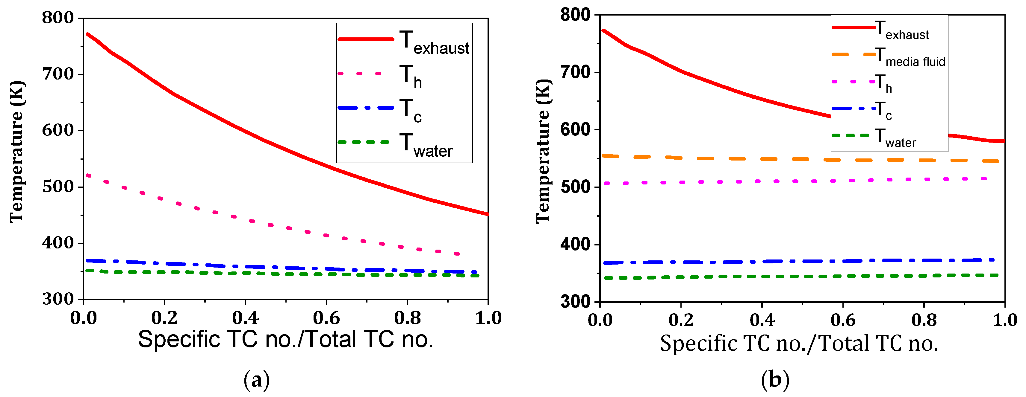
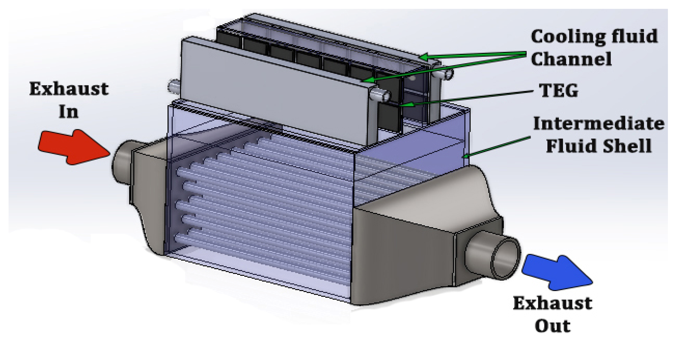
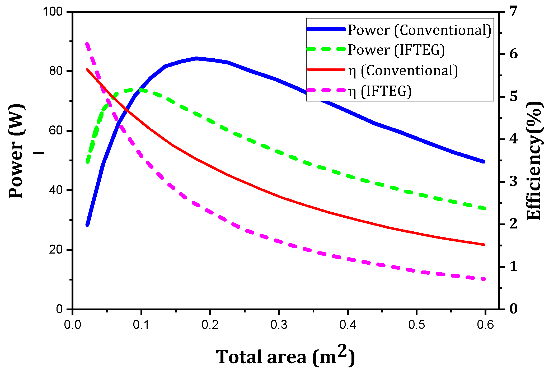
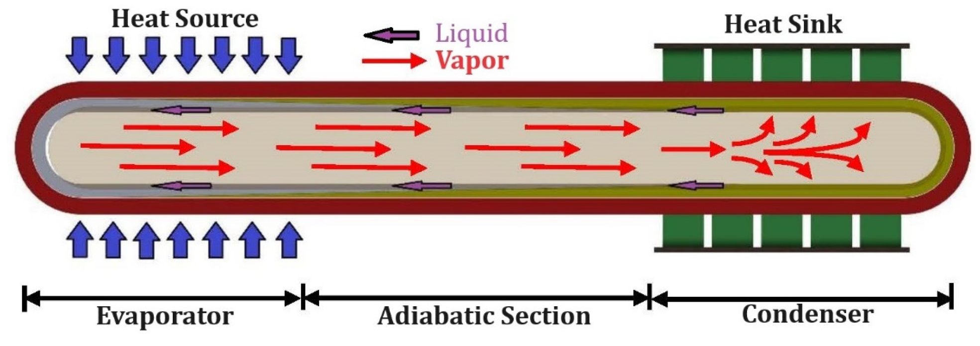
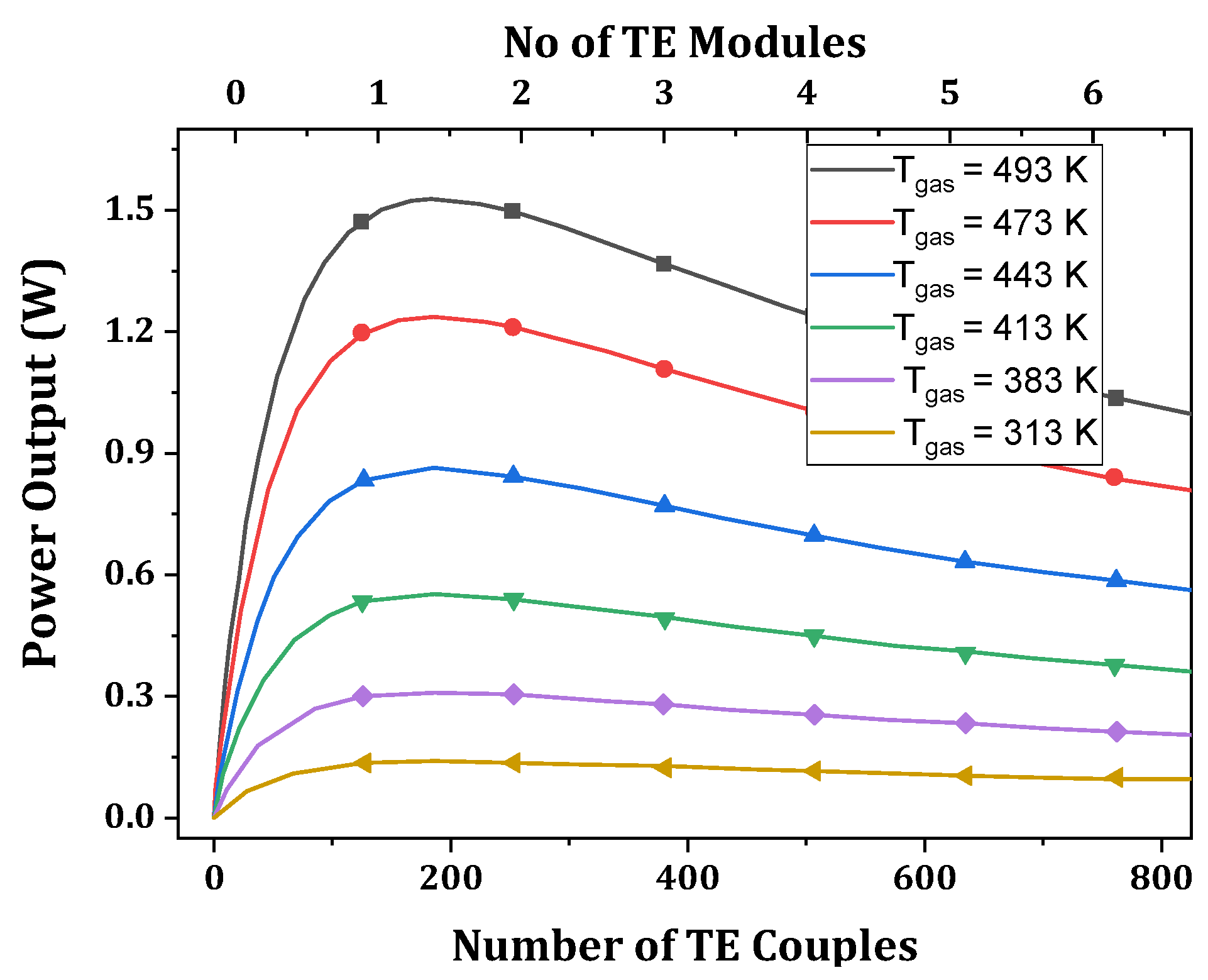
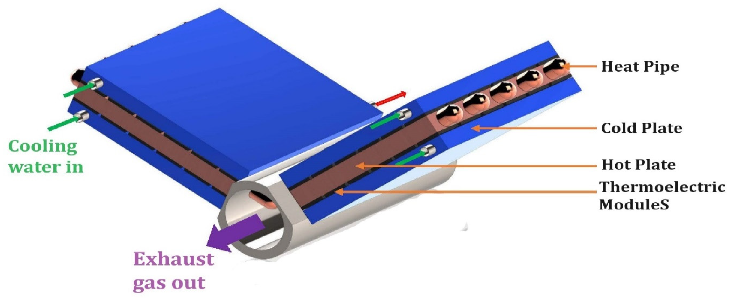

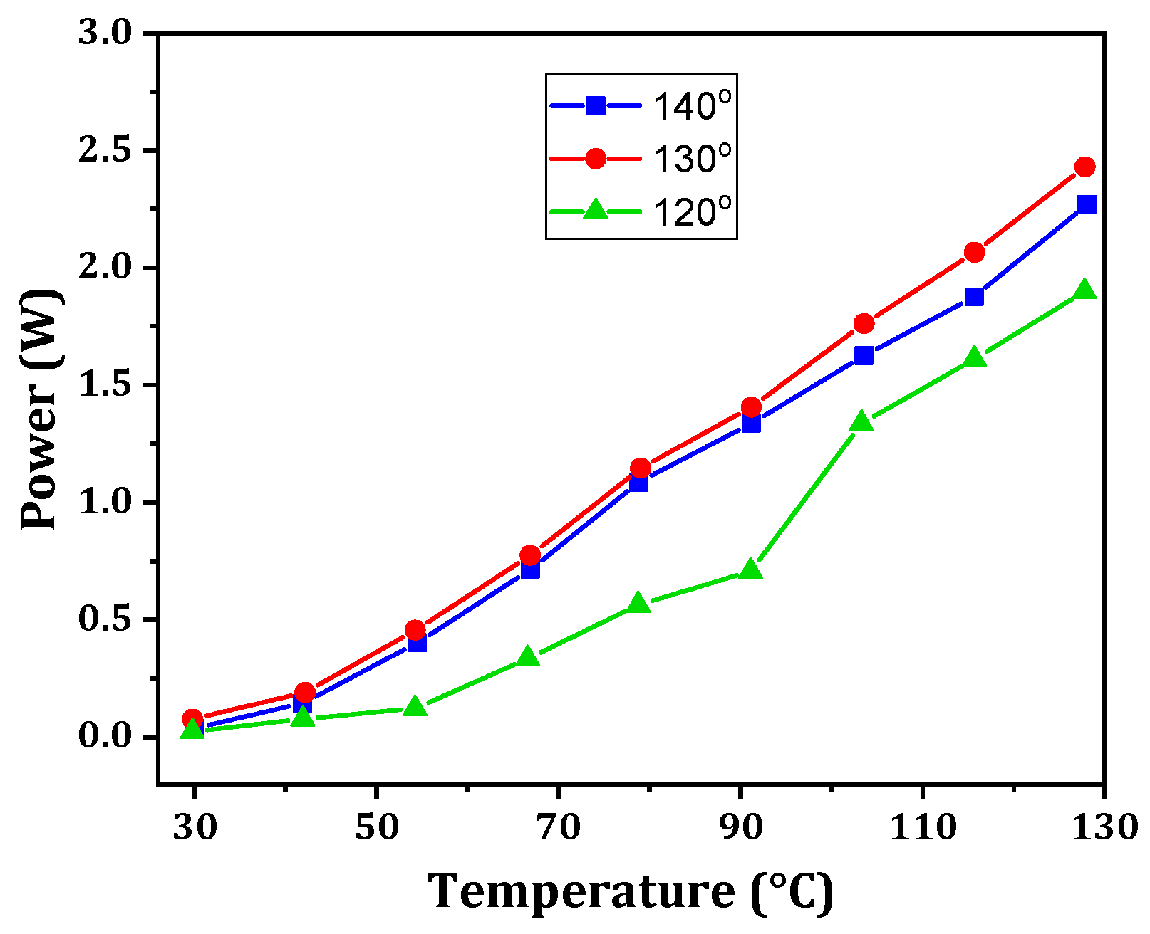
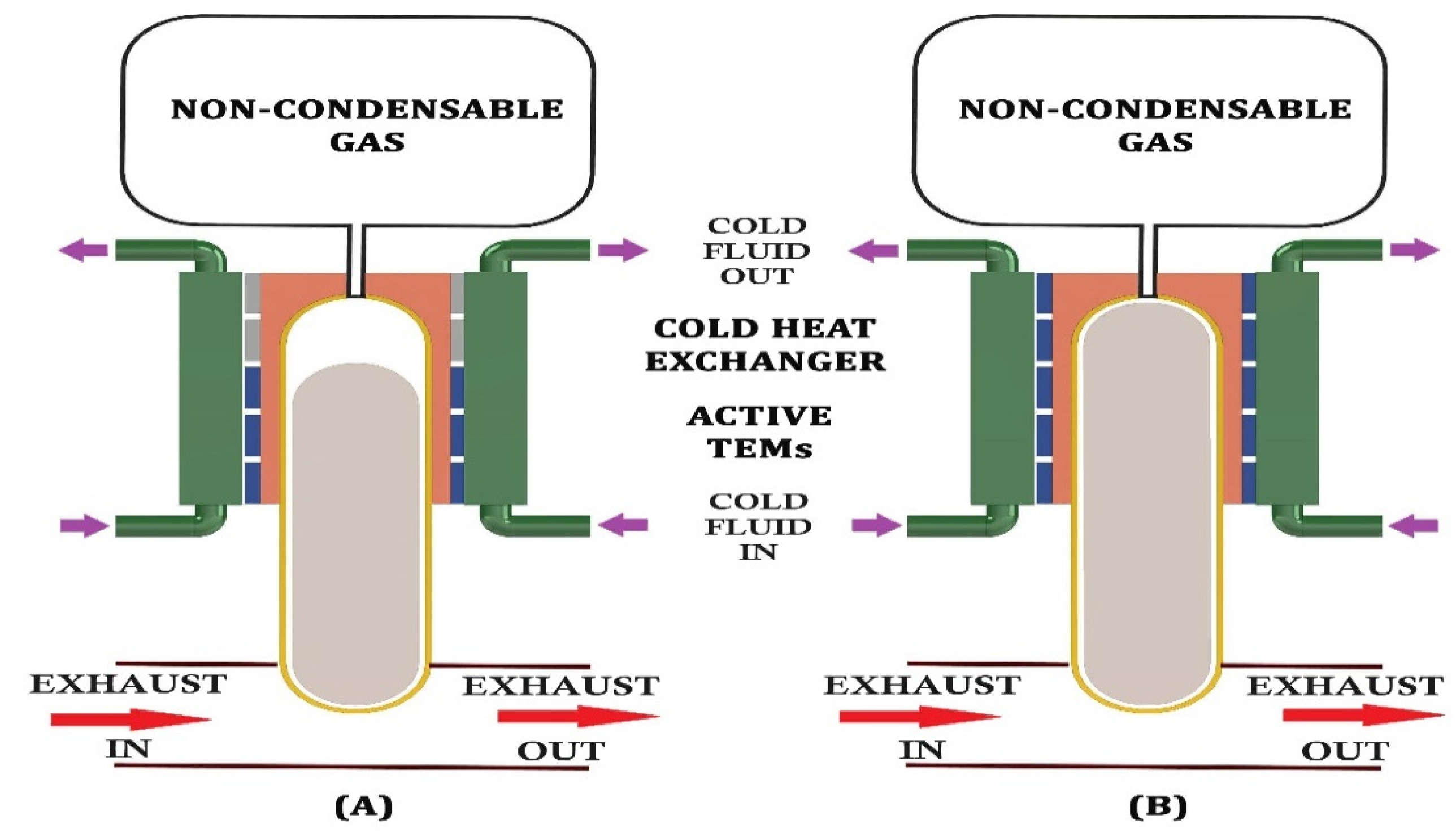


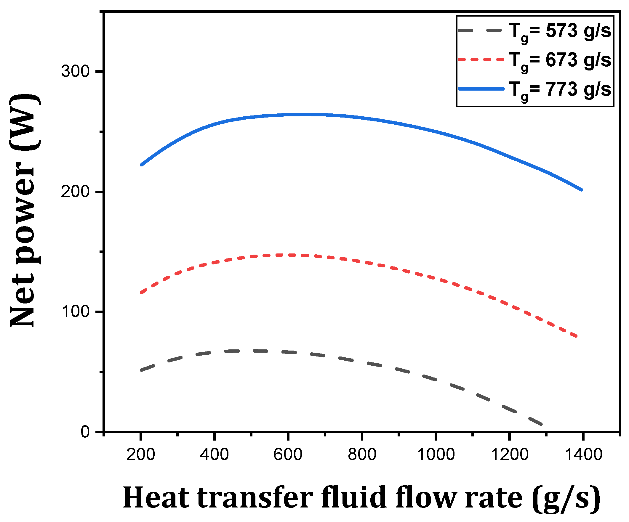
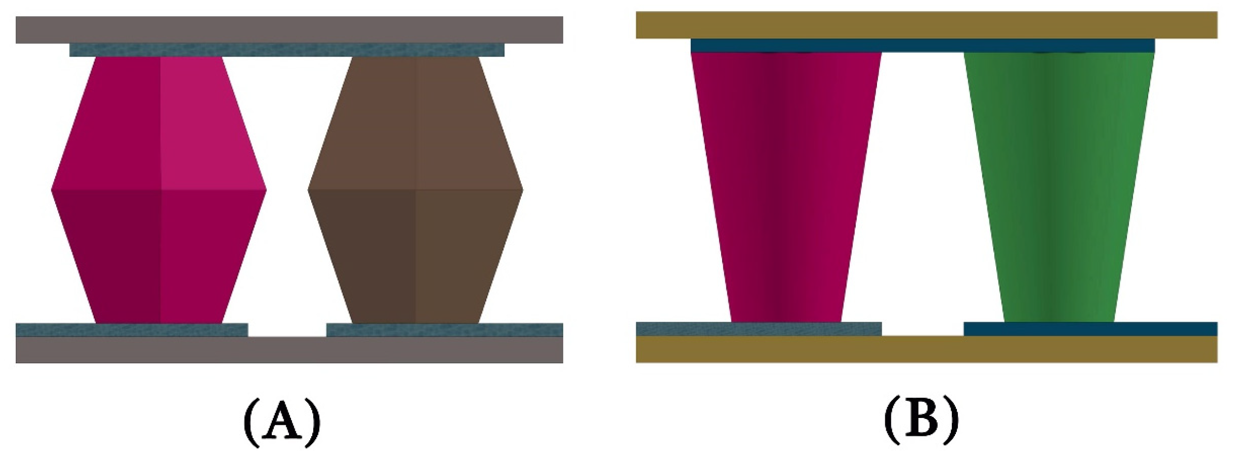
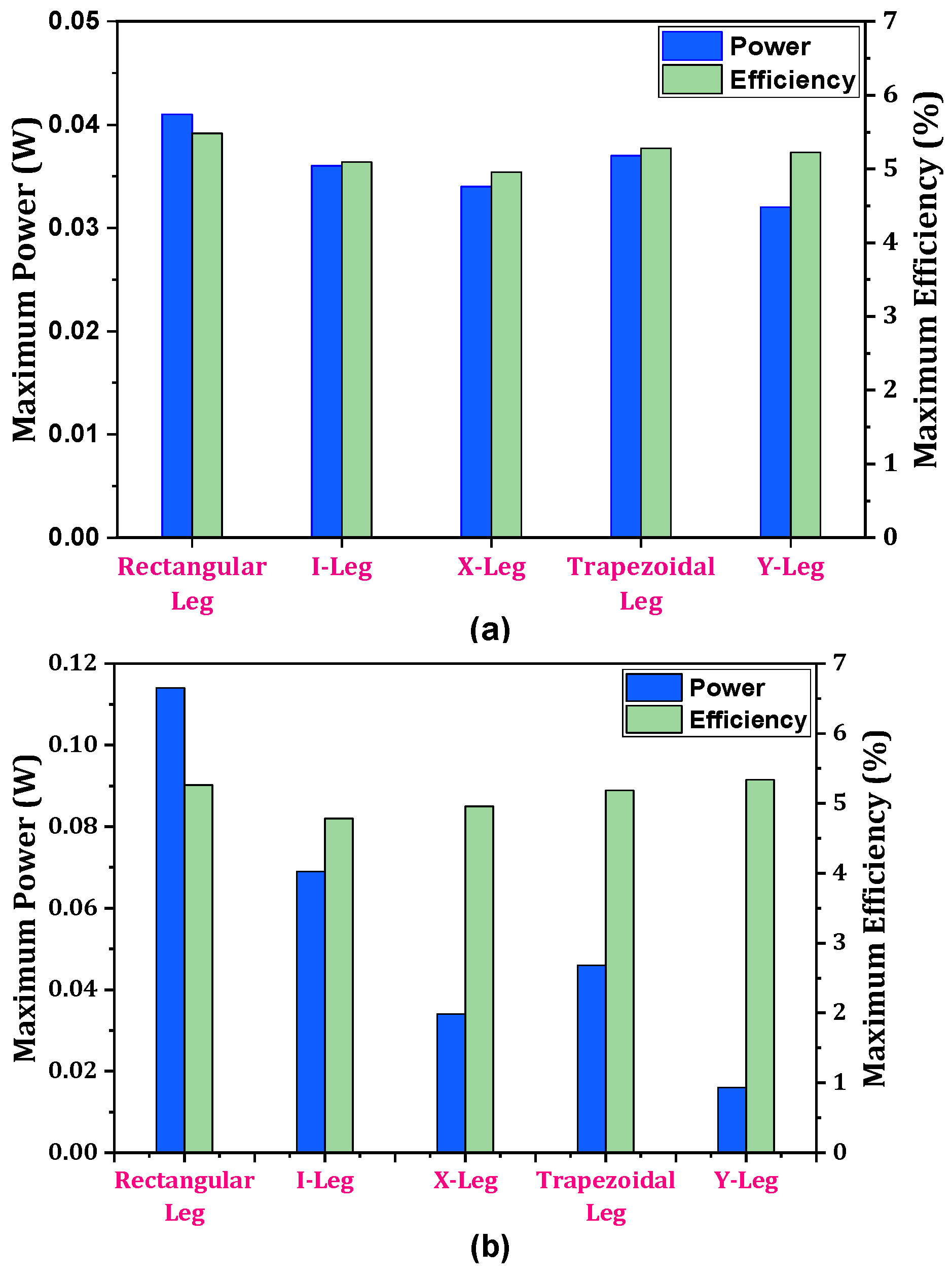

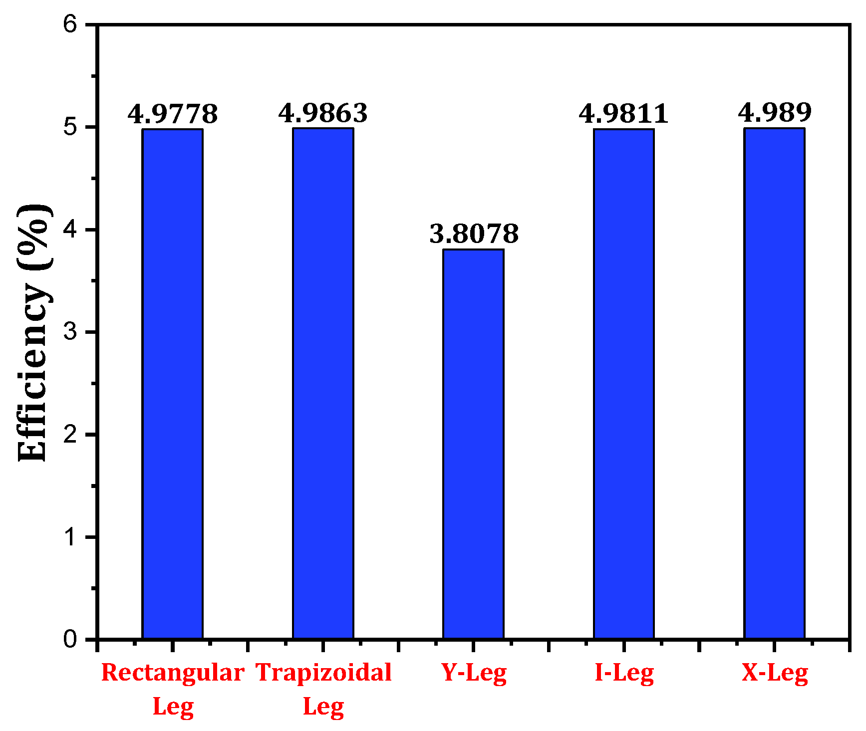
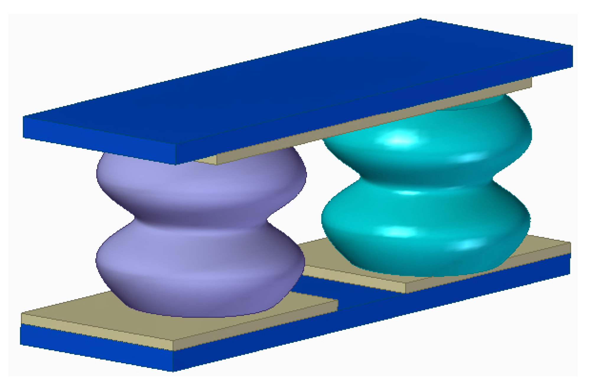
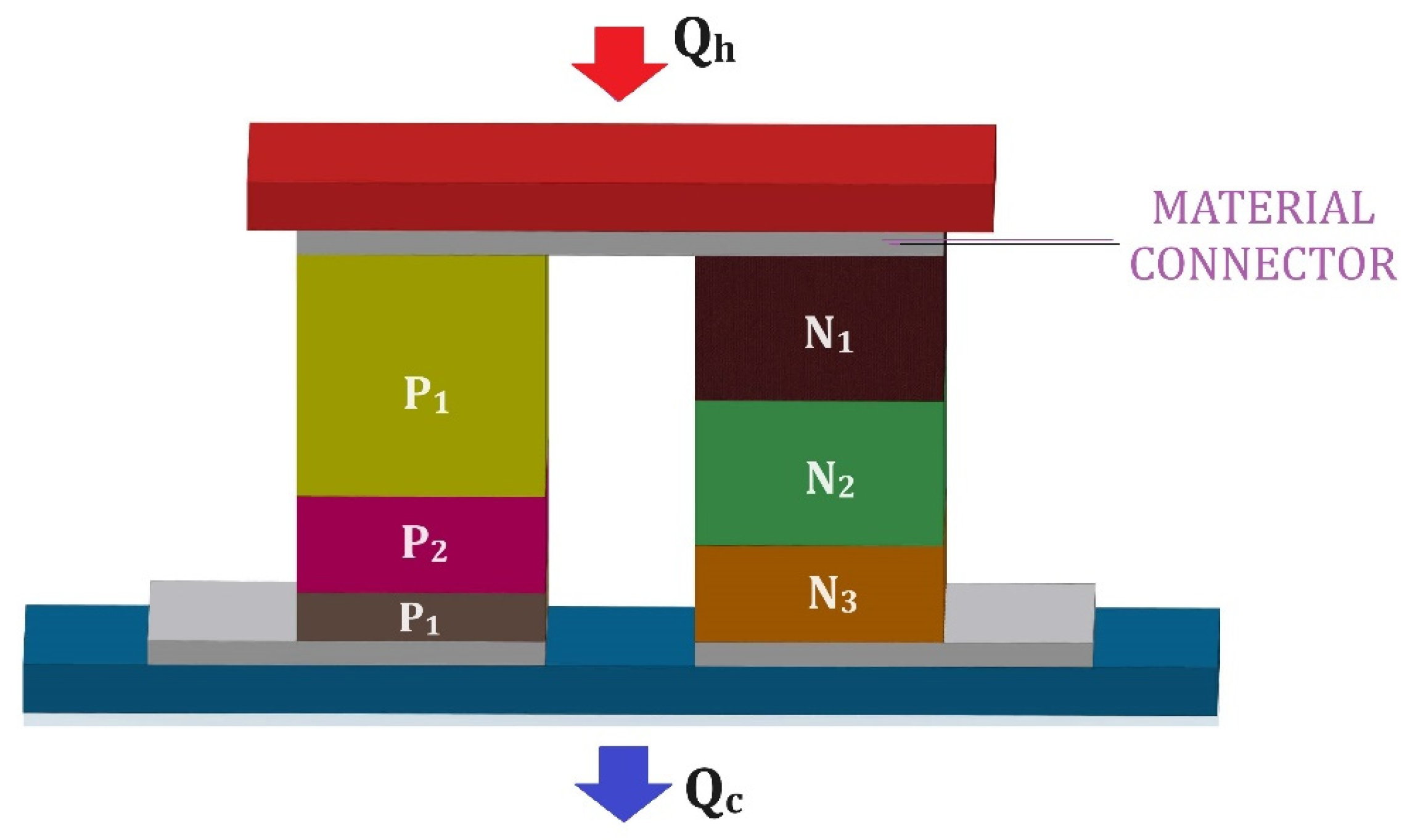
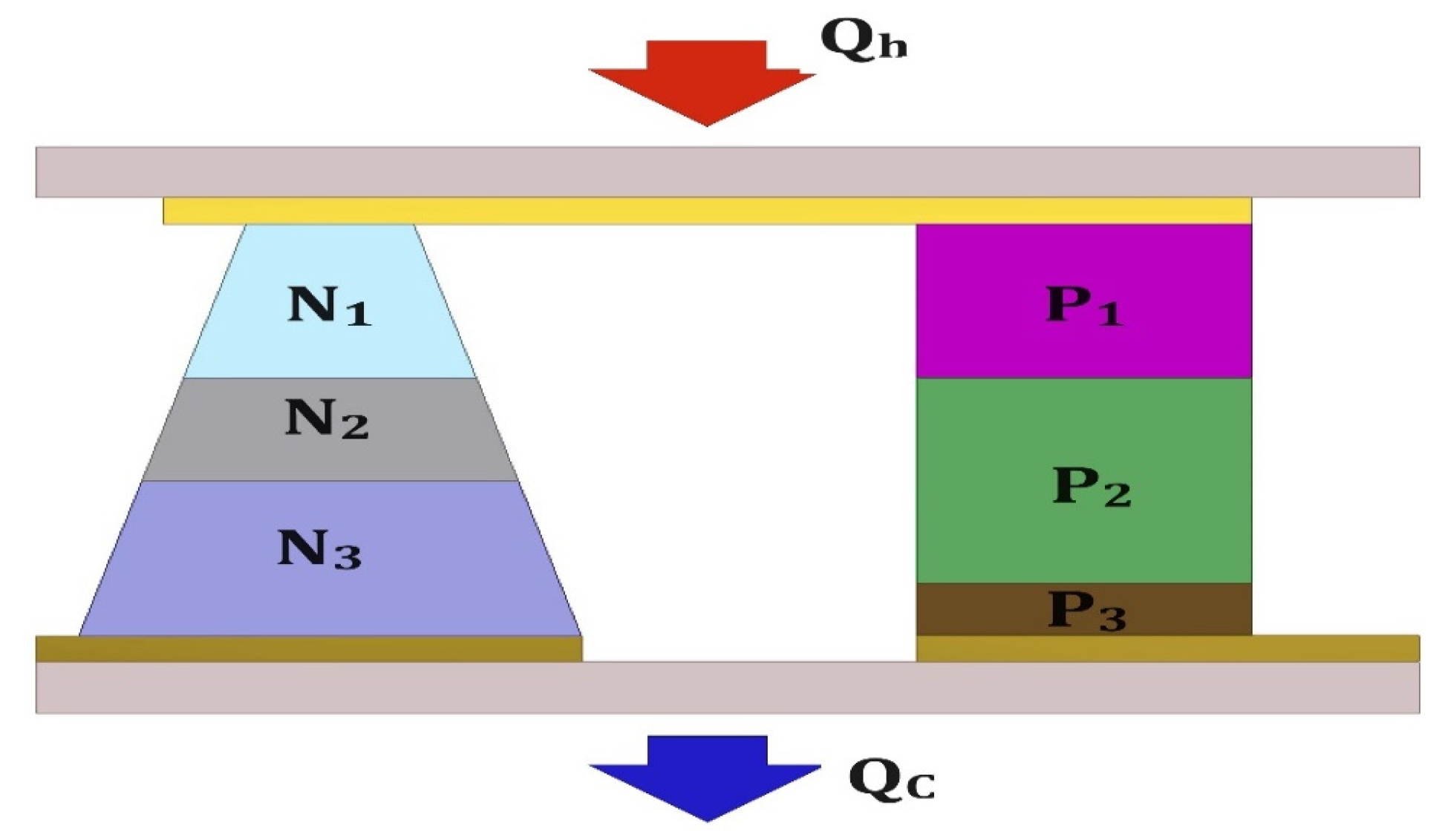
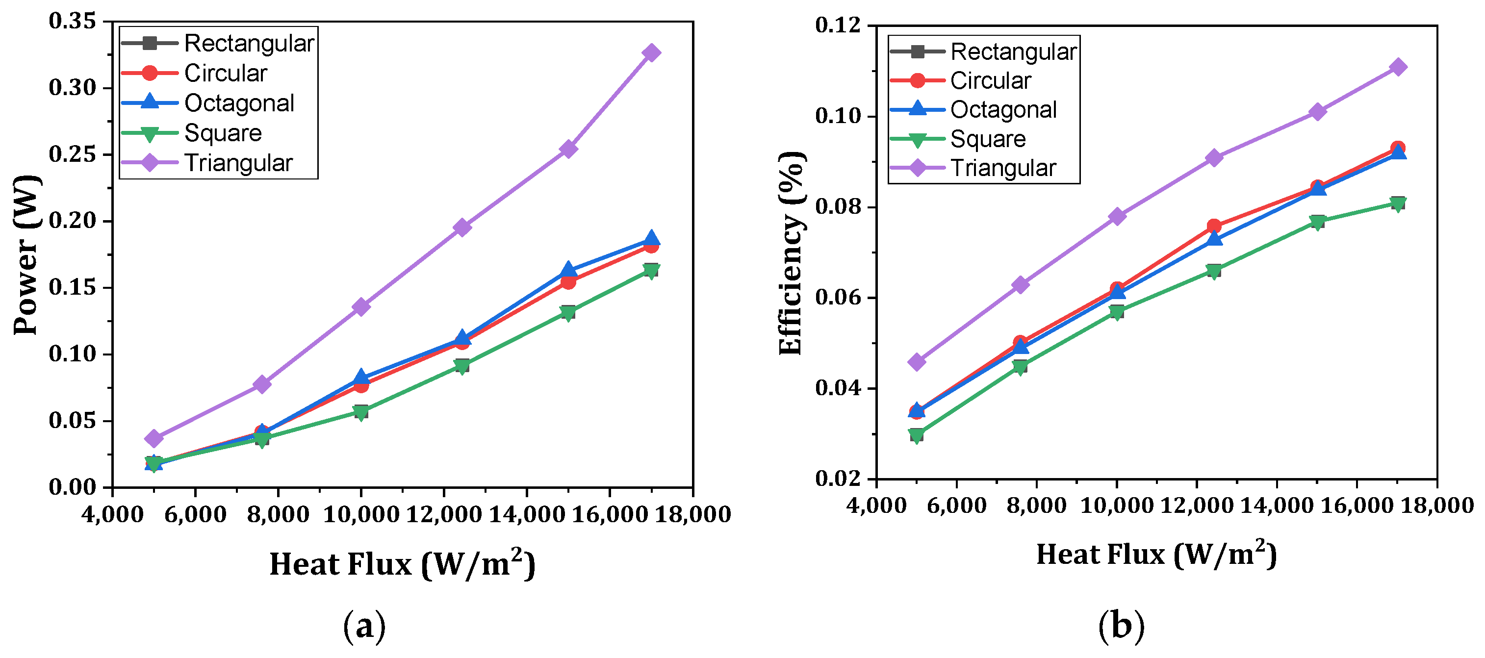
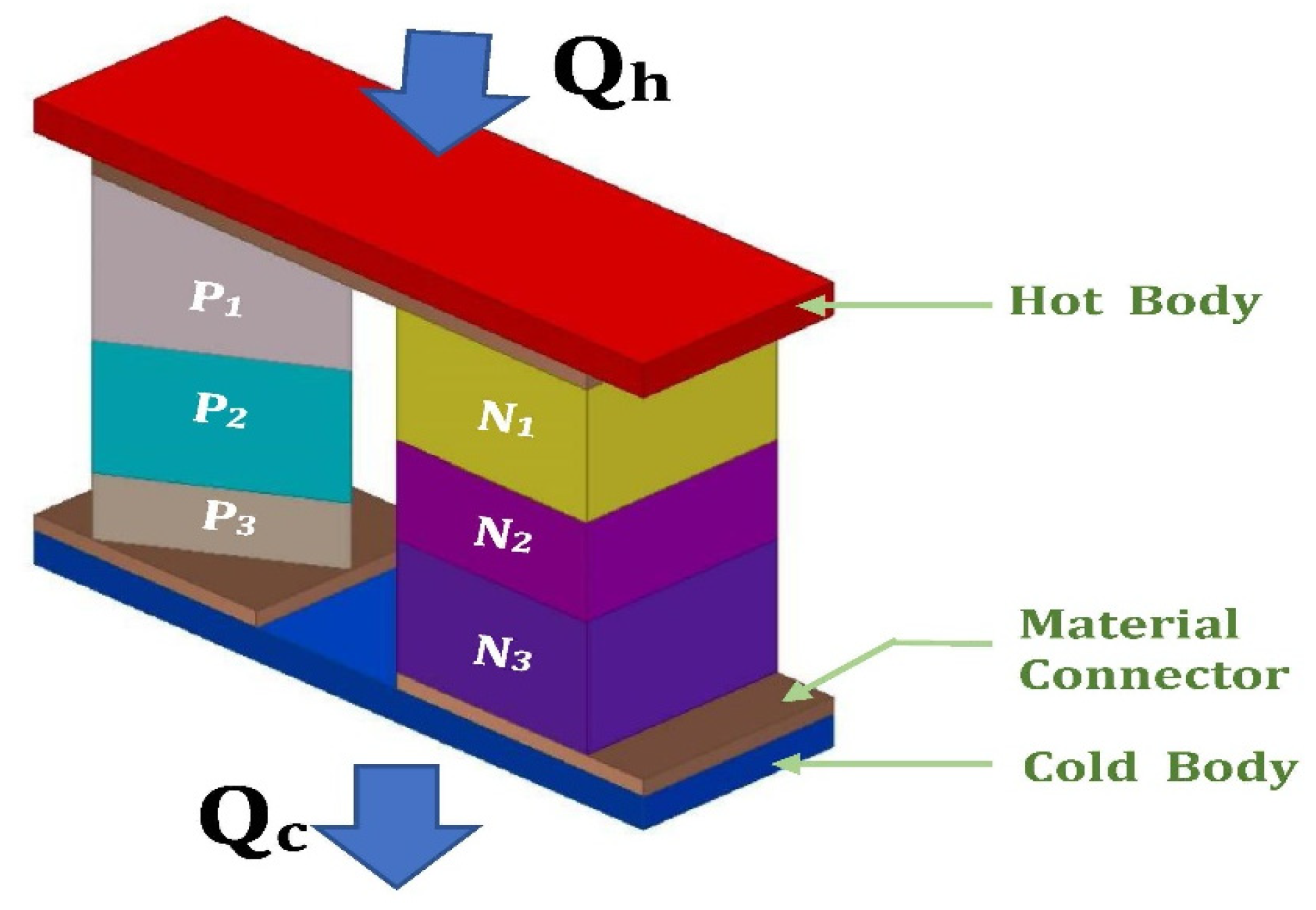
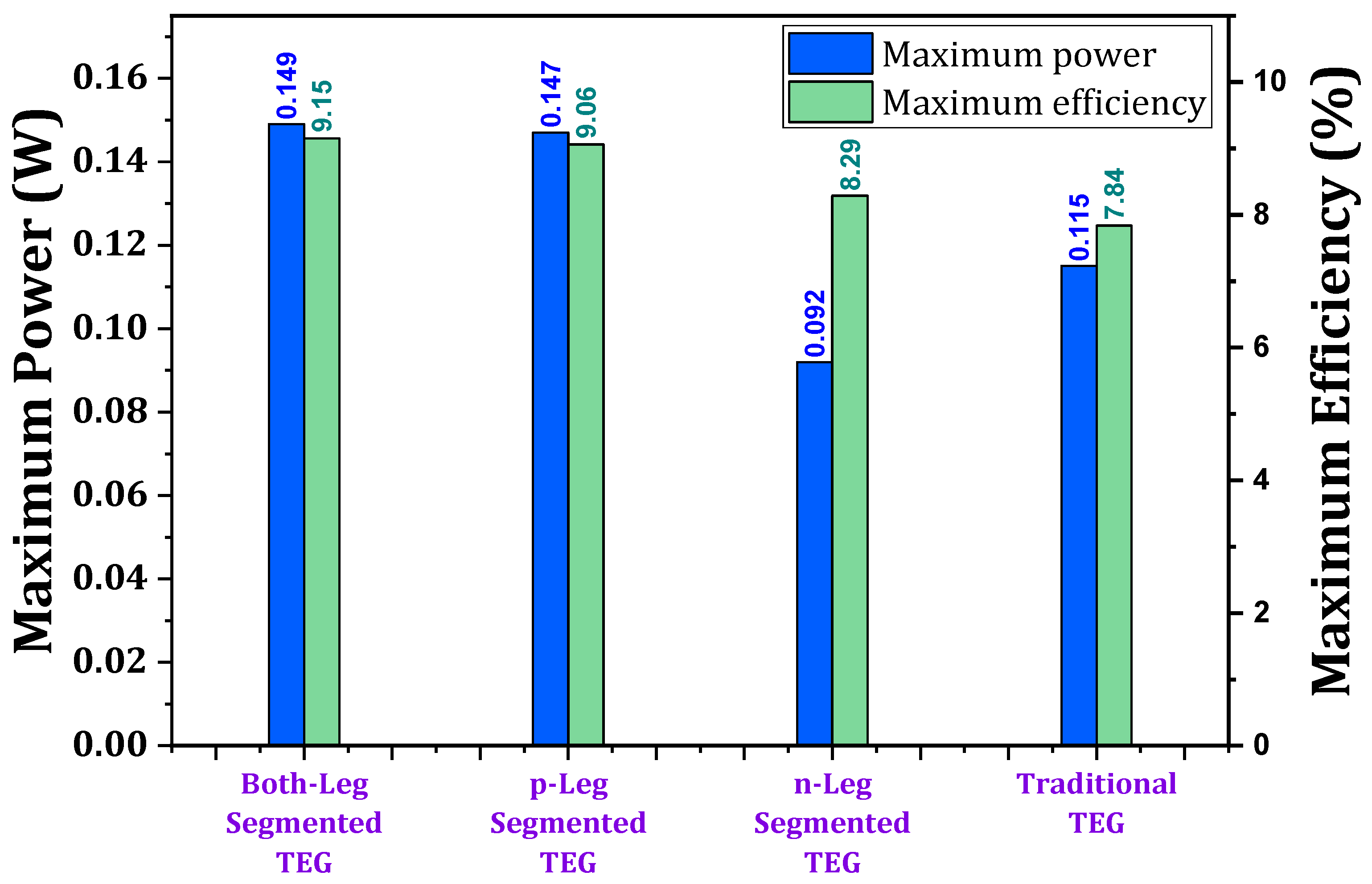
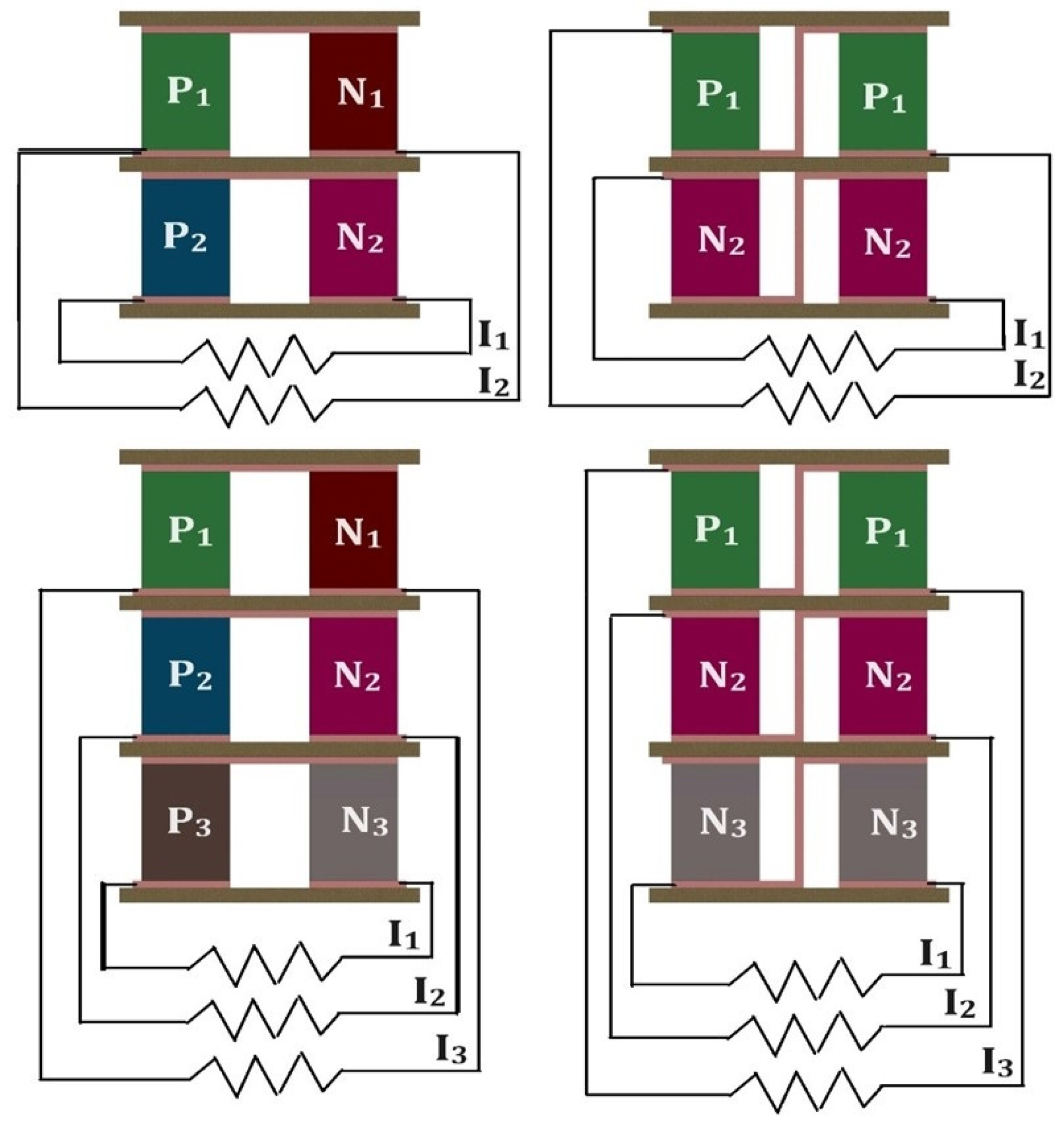
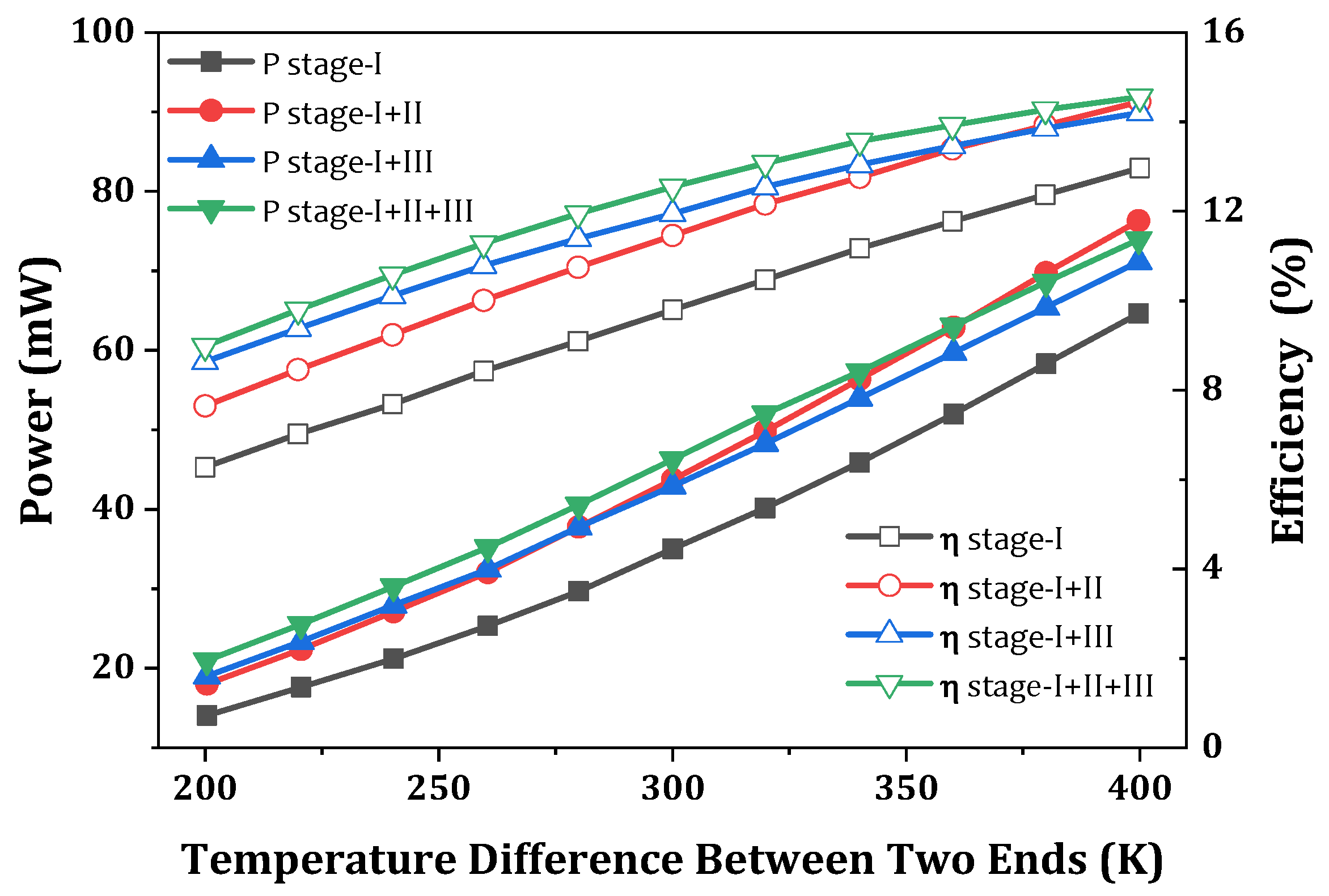

Disclaimer/Publisher’s Note: The statements, opinions and data contained in all publications are solely those of the individual author(s) and contributor(s) and not of MDPI and/or the editor(s). MDPI and/or the editor(s) disclaim responsibility for any injury to people or property resulting from any ideas, methods, instructions or products referred to in the content. |
© 2024 by the authors. Licensee MDPI, Basel, Switzerland. This article is an open access article distributed under the terms and conditions of the Creative Commons Attribution (CC BY) license (https://creativecommons.org/licenses/by/4.0/).