Abstract
A sintered wick was formed in a heat pipe through the process of sintering a mixture of copper powder with particle sizes of 100 µm and 200 µm, mixed with a pore-forming agent. The heat pipe’s thermal resistance, which affects its heat transfer efficiency, is determined during manufacturing according to the powder type, thickness of the sintered wick, and filling rate of the working fluid. Heat transfer efficiency was then tested at various inclination angles (0°, 45°, and 90°) to evaluate the performance of heat pipes. Regardless of the filling amount and test angle, the 200 μm copper powder type exhibited superior heat transfer efficiency compared to the 100 μm type. After analyzing heat transfer performance at various filling rates between 20% and 50%, it was determined that the heat pipe’s optimal heat transfer capability occurred at a working fluid filling rate of 30%. The width of the wick was directly related to the heat transfer performance.
1. Introduction
The rapid development of the IT and electronics industries has recently complicated the functional requirements for the performance of electronic equipment, and the high-power consumption of this equipment has resulted in a shorter lifetime [1]. Due to the limited space available, the heat dissipation system of aviation components experiences high acceleration. Hence, the designer must take into account safety and operational performance in dynamic conditions and various external environments, covering a wide range of frigid temperatures (−30 °C to 45 °C). Therefore, it is important to ensure the preservation of a specific standard of performance. Cylindrical copper heat pipes are ideal for heat dissipation in aircraft electrical components due to their exceptional thermal conductivity and efficient use of space. The heat pipes effectively maintain a consistent temperature for the heating element. Originally designed to control satellite temperatures, they are now widely used in different industries and applications in the electronics sector. These applications provide phase-change heat transfer with high thermal conductivity, and a number of automatic temperature characteristics for lifetime and cost-effectiveness, among other benefits [2]. The heat pipe utilizes copper wicks mounted on the inner wall of the copper pipes to circulate the working fluid from the condensing portion to the evaporation section and back again [3]. Heat is transferred to the working fluid in the evaporator through conduction, causing vaporization at the wick surface. This increases the local pressure inside the evaporator and enables the vapor to move towards the condenser. Heat is extracted at the condenser, causing the vapor to condense on the wick surface and release latent heat. Heat pipes have a significant advantage over traditional devices due to their high thermal conductance in a steady state [4].
The main factors affecting heat pipe performance include the maximum heat transfer capacity, heat conduction coefficient, heat transfer limit, and thermal resistance. Specifically, the capillary limit of copper wick is the most important variable that determines the temperature range and heat transfer limits of ground-based heat pipes, out of all the different factors that affect heat transfer.
The capillary limit in metal sintered wick heat pipes is influenced by several factors, including the diameter and shape of pores, as well as the porosity, permeability, and thickness of the sintered body. Of these requirements, achieving high porosity and permeability through sintering technology is especially important for the production of heat pipe wicks. Hence, this study applies the wick production parameters—porosity, permeability, and capillary force—which have a notable influence on the heat pipes’ performance, using the data obtained from previous research [5]. The heat transfer efficiency of heat pipes was evaluated under various conditions, including different tilting angles, copper powder sizes, wick thicknesses, and working fluid filling ratios.
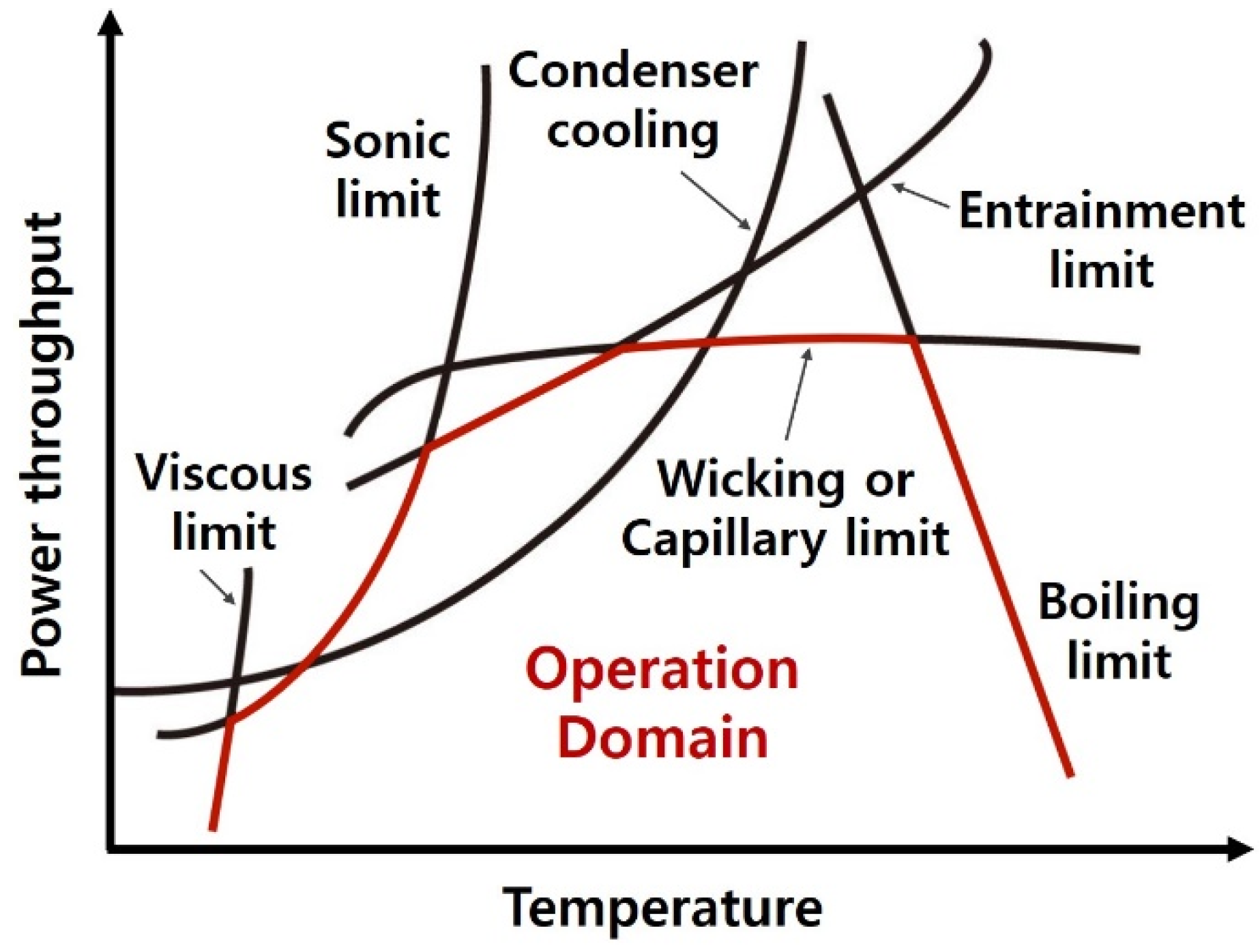
Figure 1 shows the operational boundaries of a sintered wick heat pipe [6]. It defines the limits of heat pipe performance. Each of these limitations is distinct, independent, and not interconnected. By applying individual analysis techniques for each limitation, it is possible to calculate the heat transport capacity based on the mean operating temperature (adiabatic vapor temperature). The distinct performance limits define an operational range, which is represented by the region enclosed by the combination of these individual limits. The operational range of the heat pipe is essentially the specific region or combination of temperatures and maximum transfer capacity within which it is designed to operate. Therefore, it is possible to either improve the design or ensure that the heat pipe can effectively transfer the necessary thermal load. Also, it is important to keep in mind that the determination of the average operating temperature is essential for the calculation of the heat transport capacity. The operating temperature of a standard heat pipe is generally determined by the heat input. Therefore, the heat transfer and operating temperature are interrelated. The transfer capacity of a heat pipe is influenced by several factors, including the working fluid, the wick structure, the dimensions of the heat pipe, and the operating temperature [7].

Figure 1.
Limitations to heat transport in a heat pipe.
Capillary Limitation
Each operating limit of a sintered wick heat pipe can be considered independently. The heat pipe requires the maximum capillary pumping pressure () to exceed the overall pressure drop within the pipe for it to operate effectively. This pressure drop consists of three components, namely the pressure drop () necessary for the liquid to be transferred from the condenser back to the evaporator, the pressure differential () required for the vapor to move from the evaporator to the condenser, and the gravitational head, which varies based on the heat pipe’s inclination, determines the pressure (), and can be zero, positive, or negative. In order for the heat pipe to operate correctly, it is essential that this condition is fulfilled; otherwise, the wick in the evaporator section will become depleted of moisture (dried out). The capillary limit refers to the maximum allowable heat flux at which Equation (1) [8] maintains valid. The Laplace–Young equation, represented by Equation (2), determines the highest capillary pressure () generated within the wick structure of a heat pipe [8].
where is the free surface energy of the working fluid and corresponds the effective pores radius of the wick, which can be determined for different wick structures, while θ is the contact angle between the fluid and the wick. The contact angle refers to the extent to which a liquid can spread or wet the surface of a wick structure. When a liquid wets a surface, the contact angle θ will be between 0 and π/2 radians. However, for liquids that do not wet the surface, the contact angle θ will be greater than π/2. The capillary limitation in heat pipes occurs when the combined capillary forces produced by the vapor–liquid interfaces in the evaporator and condenser are insufficient to compensate for the pressure losses caused by fluid movement. Consequently, the heat pipe evaporator becomes dried out, causing a stoppage of thermal energy transfer from the evaporator to the condenser.
2. Materials and Methods
2.1. Experimental Set Up
The experimental parameter is shown in Table 1. A copper tube sized 160 mm in length was used in the manufacturing of sintered heat pipes. All heat pipes had an outer diameter of 4 mm and an inner diameter of 3.6 mm. For the manufacturing of sintered heat pipes, two distinct copper powders were used. The first type had an average particle size of 100 µm and showed a relatively consistent size distribution. On the other hand, the second type of powder had an average particle size of 200 µm and showed a varied particle size distribution. The experiment used potassium carbonate (K2CO3) as the pore-forming agent, which exhibited a spherical morphology with an average diameter of 35 µm. A mixture was prepared by combining copper powder with a pore-forming agent, which was present at a concentration of 40%.

Table 1.
Experimental parameters of heat pipes with wick.
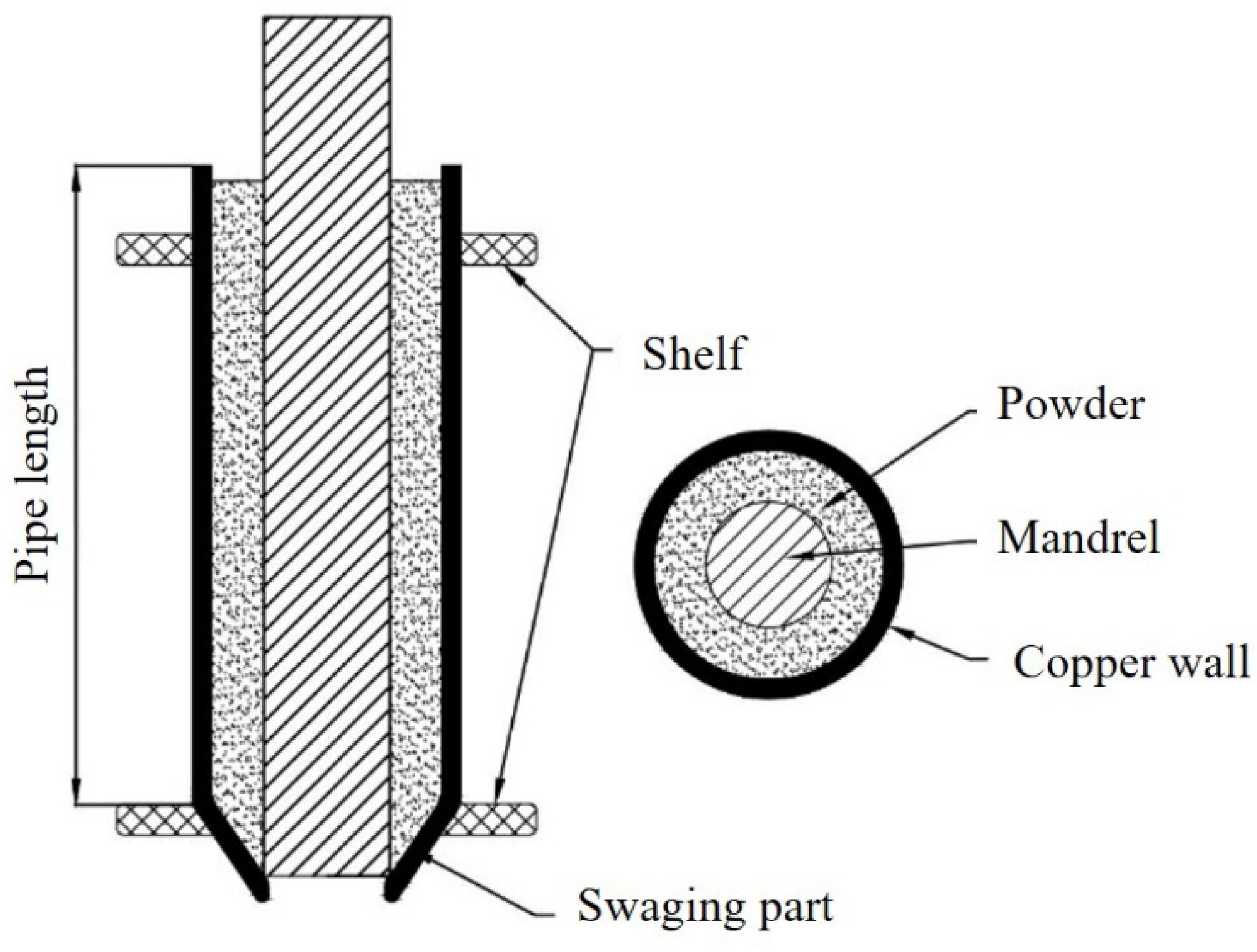
The heat pipe’s sintered wick was manufactured using a solid-state sintering method. Figure 2 represents a schematic of the heat pipe with wick before the process of sintering. A ceramic bar, with diameters of 1.5 mm, 2 mm, and 2.5 mm, was inserted into the pipe as the inner mandrel after the swaging process, which had caused one end of the pipe to shrink [9]. According to the study conducted by Jang et al. [5], the vertically positioned pipes containing powdered substances were subjected to the predetermined temperature schedule for sintering within the furnace. The sintering process was carried out under a hydrogen reducing atmosphere, with the temperature raised to 850 °C and maintained for four hours. Subsequently, the temperature was increased to 950 °C and then held for two and a half hours. Following thorough ultrasonic cleaning with distilled water and ethanol, one of the pipe ends was completely sealed using specialized equipment. The opposite end was linked to a vacuum pump in order to eliminate air and non-condensable gas from the tube.
Figure 2.
Schematic illustration of the internal layout of a pipe before the sintering.
The working fluid, made up of distilled water, was filled after the vacuum pump was set up. The manufacturing process of a sintered heat pipe was completed by using a cold weld pinch-off device to seal the opposite end in a similar manner. Each heat pipe was manufactured with the same dimensions for each filling ratio of the working fluid: 20 (0.2 g), 30 (0.3 g), 40 (0.4 g), and 50 (0.5 g) % volume. After the heat pipes were processed, a basic test was conducted to prevent any leakage or improper sealing, which could result in a decline in the heat pipe’s efficiency.
2.2. Experimental Apparatus and Procedure
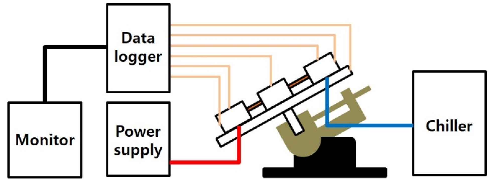
In order to measure the thermal efficiency of a heat pipe, a standardized testing apparatus was set up. This apparatus included an experimental sector, a heating section, a cooling section, a movable apparatus with adjustable angle, a data logger (YOKOGAWA, DA100), and a computer unit, as shown in Figure 3. Typically, a water-cooler circulating system is usually used to evaluate the efficiency of heat pipes. This method is similar to natural convection evaluation techniques, except for the use of water cooling. The temperature of each component was measured using K-type thermocouples. The DC power supply provided heat to the evaporator, while the chiller was used to cool the condenser with water.
Figure 3.
Schematic illustration of the experimental test apparatus.
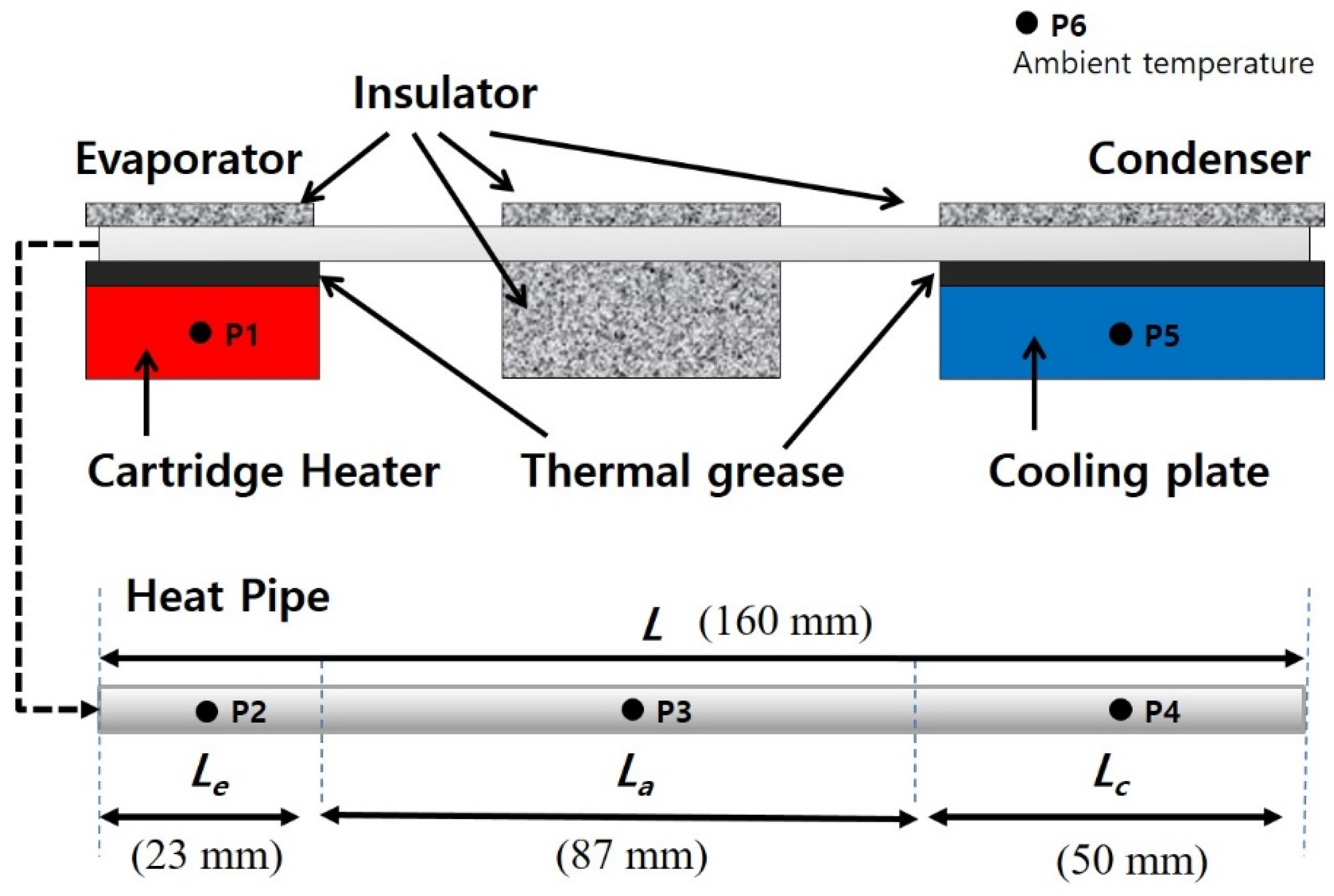
The experimental procedure for conducting the temperature rise test at each tilting angle was as follows: At first, the samples were fastened onto the test bench. Secondly, as shown in Figure 4, six thermocouples were positioned on the wall surfaces of the heat tubes, cartridge heater, cooling plate, and ambient temperature. The thermocouples have been divided into two groups for the evaporator, with one group for the adiabatic section and the other group for the condenser section. The thermocouples were placed at distances of Le = 23 mm, La = 87 mm, and Lc = 50 mm from the starting point of the evaporator section. Each thermocouple was affixed to its respective center within each division using heat-resistant polyimide tape (Kapton). Thermal grease was sprayed to the heat block and cooling plate in order to enhance thermal conductivity where they were in contact with the heat pipe. Each test sector was covered with an insulation block to reduce the heat loss from the evaporator, adiabatic, and condenser sections, all of which were fastened with jointers. The heat pipe inclination angle was adjusted from 0° to 90° for the tilting angle test, using a variable angle holding table. The DC power supply is employed for setting the heat power input for the evaporator section. Furthermore, the temperature data in a stable state were recorded using a data logger, with an interval of approximately 60 min between each input heating load. The computer also stored steady-state temperature data for the purpose of data reduction and analysis [10].

Figure 4.
Schematic illustration of the configuration of the test device and the locations of thermocouples.
The overall thermal resistance of a heat pipe defined by the following Equation (3) [11]:
where and are the temperature of the evaporator and condenser sections, respectively. The heat input power, denoted as , is controlled by the voltage (V) and amperage (I). The occurrence of heat pipe dry-out has been attributed to a rapid increase in thermal resistance. If an abrupt change occurs, the test is stopped, and the sample is extracted from the device. Conversely, the input power gradually increases once more.
3. Results
3.1. The Comparison of Heat Transfer Performance According to Cu Powder Type
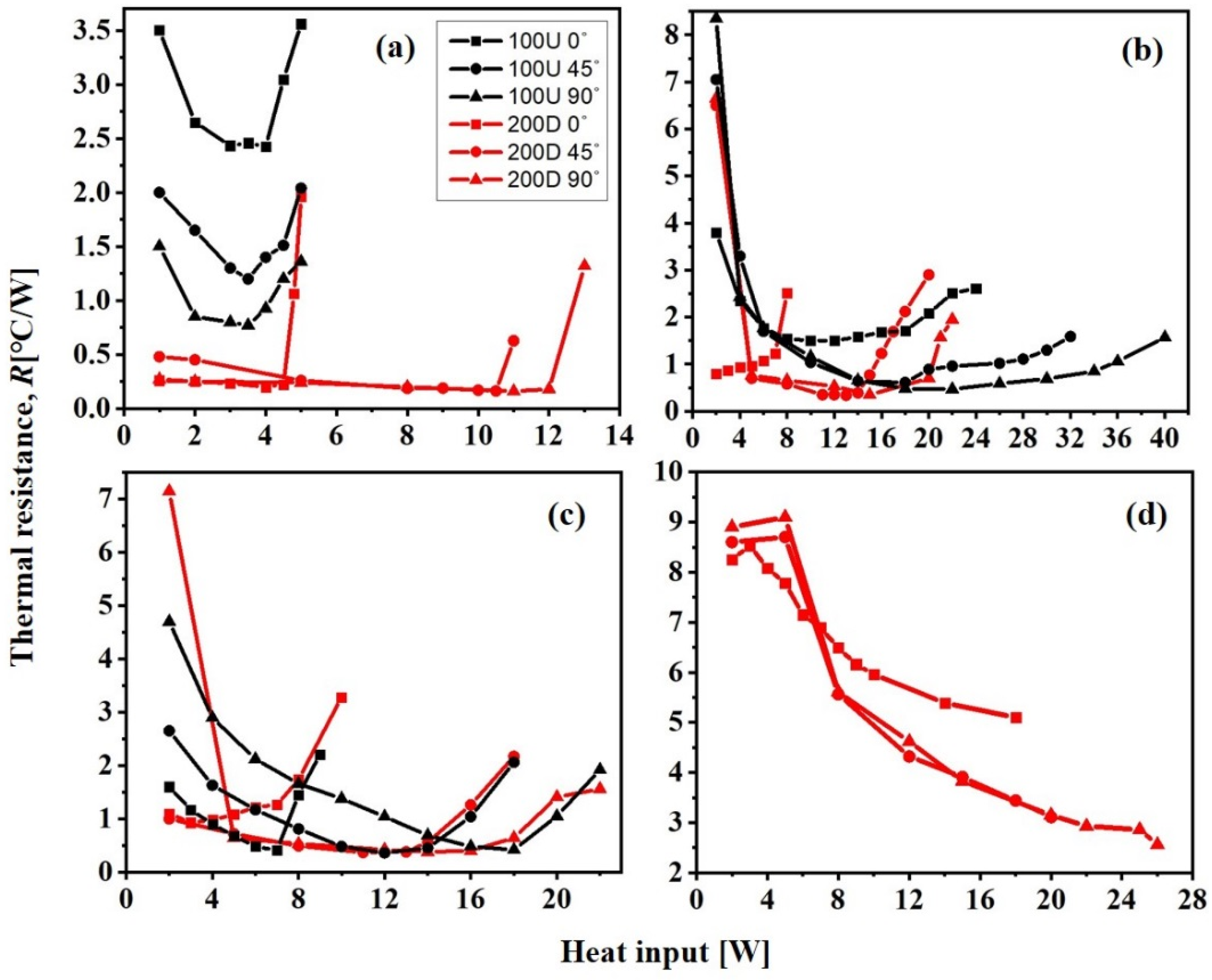
Figure 5 shows the thermal resistance results for samples 100 U and 200 D. The test angles of 0°, 45°, and 90° are included, as well as the working fluid filling ratio, which ranges from 20% to 50%. The sintering process used a mandrel of 2 mm in diameter, resulting in the formation of a wick with a thickness of 534.7 µm. For heat inputs of 12 W or less, the overall thermal resistance of the 200 D sample was lower than that of the 100 U sample.
Figure 5.
Thermal performance of a heat pipe according to the Cu powder size, the tilting angle, and filling ratios of the working fluid of (a) 20%, (b) 30%, (c) 40%, and (d) 50% (mandrel: 2 mm diameter).
Figure 5a shows the thermal resistance values of the 100 U and 200 D samples when the working fluid filling level is at 20%. When the test is conducted at angles of 45° and 90°, the 100 U sample exhibits dry-out at a heat input of 3.5 W. However, the 200 D sample has a higher Qmax value of 10 W or more. At a 30% filling ratio of the working fluid, the thermal resistance of 100 U is higher than that of 200 D, as shown in Figure 5b. The specimens showed comparable drying out points at both 45°and 90°, with few differences. Nevertheless, the thermal resistance of the 200 D specimen was determined to be lower than 100 U. Figure 5c,d shows that the heat pipe encountered operational challenges and showed a notable initial thermal resistance when the filling ratios were set at 40% and 50%. Therefore, even after subjecting the heat block to a rise in temperature of 120 °C, it was not possible to determine the dry-out point.
Based on the previous capillary force test results, it is evident that the capillary force () is influenced by a complex correlation with both the porosity and the effective radius of the wick’s pores (). The 100 U sample had the largest value of 241.31 µm, and the 200 D sample had the lowest one of 155.73 µm. Furthermore, the porosity value of 100 U was found to be 59.07%, which was higher than the porosity value of 200 D, which was estimated to be 56.47% [5]. Nevertheless, the 200 D sample exhibited stronger capillary forces. This could be attributed to the smaller effective radius () value, which indicates that the capillary force is mainly affected by the value. Moreover, empirical evidence suggests that the powder filling density of 200 D is higher than that of 100 U, primarily because it covers a wider range of particle sizes. Therefore, applying a 200 D powder-based wick has significant advantages in creating small, efficient pore sizes. This corresponds to the observation that 200 D has superior thermal conductivity compared to 100 U.
3.2. Comparison of Heat Transfer Performance According to Sintered Wick Thickness and Test Angle
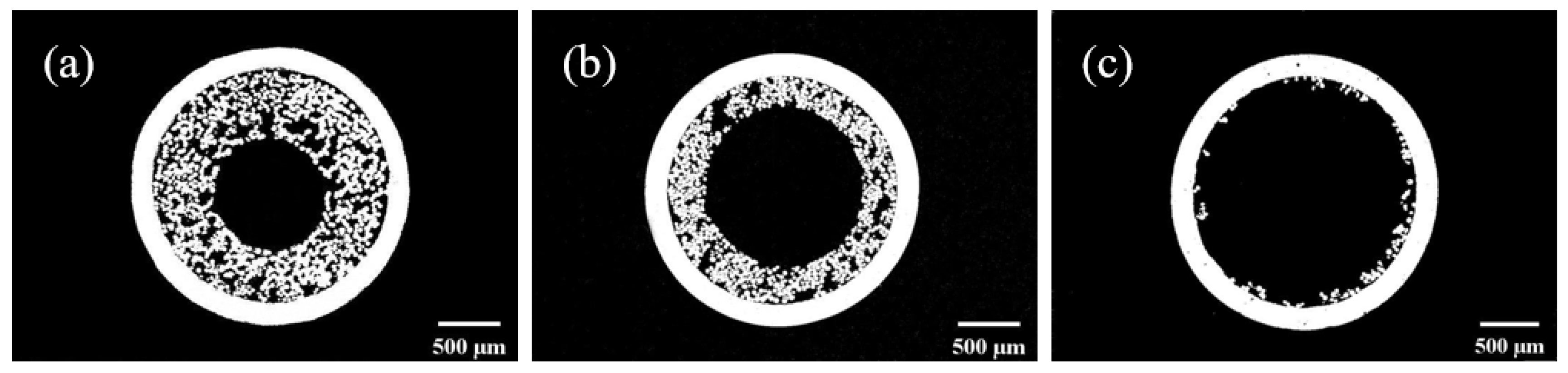
The heat pipe wicks were fabricated by sintering copper powders, with the inclusion of ceramic inner mandrels sized 1.5, 2, and 2.5 mm in diameter. Figure 6 exhibits cross-sectional SEM images of a heat pipe with a wick that has been installed subsequent to the sintering process. The average thickness of the wick structure was measured to be 902 µm, 534.7 µm, and 179.1 µm for mandrel diameters of 1.5, 2, and 2.5 mm, respectively.

Figure 6.
SEM images of the cross-section of a sintered heat pipe according to the thickness of the wick. (a) 902 µm (mandrel: 1.5 mm), (b) 534.7 µm (mandrel: 2 mm), and (c) 179.1 µm (mandrel: 2.5 mm).
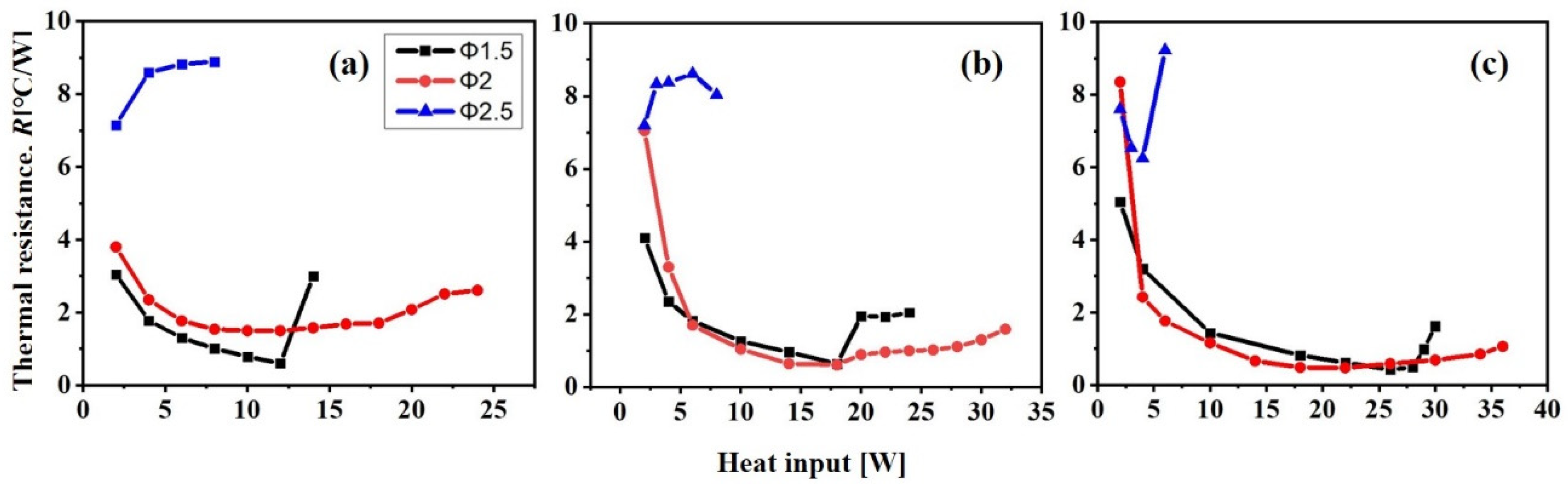
Figure 7 shows the thermal resistance measured in the 100 U sample while varying the mandrel diameters and tilt angles. The thermal resistance primarily depends on the surface area of the interface between the liquid and vapor phases, as indicated by theoretical analysis [12]. The sample with the smallest wick thickness (tw) of 179.1 µm (mandrel diameter: 1.5 mm) showed the highest thermal resistance, indicating the lowest thermal transfer capability in comparison to all other tested samples. Furthermore, the initial thermal resistance of this sample exhibited a notable difference compared to the thermal resistance of the other samples. In addition, the temperature at the evaporator section increased quickly in response to the heat input, ultimately reaching a maximum of 70 °C at a heat input of 5 W. The substantial rise in temperature caused difficulties for accurately determining the final Qmax value. The present problems come from the inadequate thickness of the sintered wick, hindering the effective transfer of the condensed working fluid from the condenser section to the evaporator section via capillary force. Therefore, the pipe with the thinnest wick exhibited a comparatively lower heat transfer efficiency than the pipe with a thicker wick.
Figure 7.
Thermal performance of heat pipe in relation to heat input for various mandrel diameters and tilt angles: (a) 0°, (b) 45°, and (c) 90°. The wick was made with 100 U powder and filling ratio was 30%.
The heat resistance remained consistently low for both the 902 µm and 534.7 µm wick thicknesses, regardless of the test angle. Furthermore, it can be observed that the heat pipe with a wick thickness of 534.7 µm has a higher dry-out temperature compared to the heat pipe with a thickness of 902 µm at all tilting angles. Therefore, it can be concluded that the heat pipe with a medium-sized wick thickness of 534.7 µm has the superior heat transfer capability. This phenomenon can be explained by the decrease in the width of the vapor passage as the wick thickness increases, along with the corresponding increase in the surface area that comes into contact with the working fluid.
As the thickness of the wick increases, the surface area of liquid that can be absorbed by the wick also increases. This leads to a reduction in the pressure drop because the fluid can flow more easily through the wick. However, Li, Y et al. [13] observed that the pressure loss increased in direct proportion to the increase in the thickness of the heat pipe wick. They explained that the movement of the working fluid towards the evaporation section is controlled by the capillary force, causing the wick to become wet in multiple directions. As a result, there is a decrease in the amount of working fluid that has to be transported to the evaporation section when the wick is excessively thick. Moreover, excessive thickness of the wick leads to a decrease in the cross-sectional area available for the passage of vapor through the pipe. Consequently, the friction coefficient of vapor in the vapor flow passage rises, thus serving as a constraint on the maximum heat transfer capacity. Conversely, if the wick is not thick enough, the passage becomes too small for the condensed working fluid in the condensation sector to be transported to the vapor sector by capillary force.
The experimental results in this study coincide with the theory mentioned above, indicating that the optimal thermal transfer performance was attained by employing a medium-sized wick thickness of 534.7 µm, which was produced using a mandrel with a diameter of 2 mm.
When the angle is 0°, it is observed that the thermal resistance of the wick with a thickness of 902 µm is relatively lower than that of the wick with a thickness of 534.7 µm. This difference can be attributed to the preferential movement of the working fluid within the heat pipe towards one side, caused by the force of gravity. This bias results from the basic assumption that the wick on one side initiates its operation at relatively lower temperatures. Reducing the thickness of the wick causes the absorbed working fluid to accumulate mostly on the lower side of the heat pipe. The formation of a bubble barrier occurs as a result of the large amount of working fluid, even at lower temperatures, which hinders the vapor’s movement. Consequently, it has been determined that the initial thermal resistance exhibited a significant value [14].
Therefore, it is important to take into account two factors when determining the thickness of the wick. Firstly, the wick should be thick enough to enable the transfer of the condensed internal working fluid from the condenser section to the vapor section using capillary force. Furthermore, it is also necessary that the internal space of the pipe is sufficiently large to ensure a proper pathway for the flow of vapor.
3.3. Comparison of Heat Transfer Performance According to the Working Fluid Filling Ratio
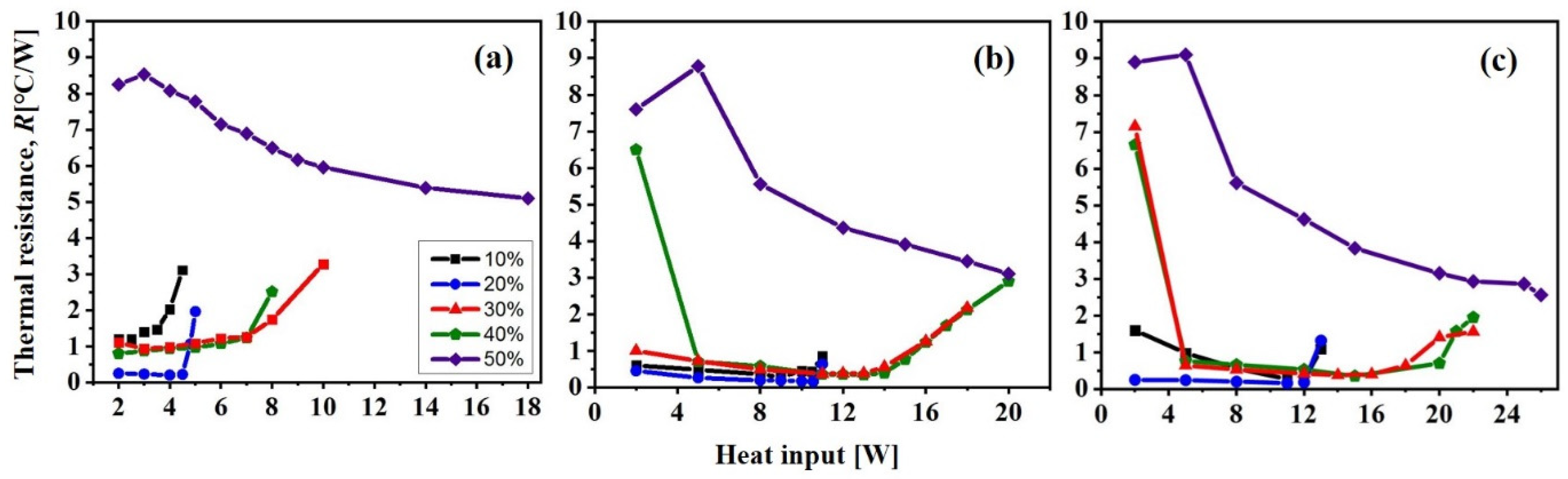
Figure 8 shows the heat transfer performance of the heat pipe in relation to the filling ratio (Rf) of the working fluid at various tilting angles. The heat pipes in the experimental setup used a wick with the same wick thickness of 534.7 µm (mandrel diameter: 2 mm), which was made by employing 200 D copper powder. Samples were prepared by injecting 0.2 g (Rf = 20%), 0.3 g (Rf = 30%), 0.4 g (Rf = 40%), and 0.5 g (Rf = 50%) of the working fluid into the heat pipe, giving a total filling amount of 1 g.
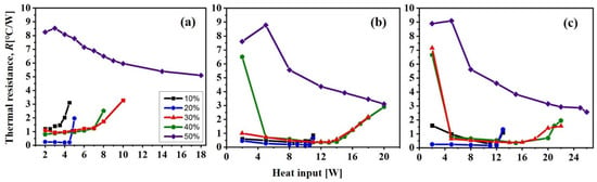
Figure 8.
Thermal performance of the heat pipe according to the working fluid filling ratio at different test angles of (a) 0°, (b) 45°, and (c) 90°.
At a filling ratio (Rf) of 50%, the thermal resistance exhibited the highest value at all test angles. In addition, the thermal resistance showed a tendency to decrease as the heat input increased. The initial thermal resistance is very high due to the excessive amount of working fluid, which requires more heat input to produce the latent heat of evaporation. The maximum permissible temperature for general electronic products employing semiconductors is 125 °C [15]. The dry-out temperature could not be determined, even when the heat block temperature was raised to 130 °C or higher. Thus, when the heat pipe’s wick has a thickness of 534.7 µm, it is evident that the heat transfer capacity significantly decreases when it is filled to a rate of 50% due to excessive filling. On the other hand, at a filling ratio (Rf) of 20%, the thermal resistance values consistently show the lowest levels, indicating superior thermal transfer capability regardless of the tested angles. However, the dry-out point is relatively low, meaning that the pipe cannot effectively perform heat transfer at high temperatures. The samples with Rf = 30% and 40% exhibit the same heat resistance values at angles of 45° and 90°, as shown in Figure 8b,c. Nevertheless, when subjected to a power exceeding 13 W, the sample with the Rf of 40% exhibits a slightly higher thermal resistance compared to the sample with the Rf of 30%. Two key requirements for an efficient heat pipe are low thermal resistance and a moderately high dry-out point. According to these criteria, it can be concluded that this heat pipe exhibits optimum heat transfer properties when the filling ratio (Rf) of the working fluid is 30%.
As the filling ratio (Rf) of the working fluid rises, there is a proportional increase in the amount of fluid that undergoes a phase transition into vapor, as well as an increase in the quantity of fluid that returns back to a liquid state in the condenser section. The higher initial thermal resistance observed in the condenser section may be attributed to the presence of residual working fluid, which acts as a liquid barrier. Furthermore, when there is an extensive amount of fluid, the heat input required to convert the working fluid into vapor also increases. In this case, the thermal resistance remains high at lower temperatures. As the temperature rises, the liquid block reduces gradually, resulting in an increase in heat transfer capacity. As it improves, the corresponding value of Qmax increases.
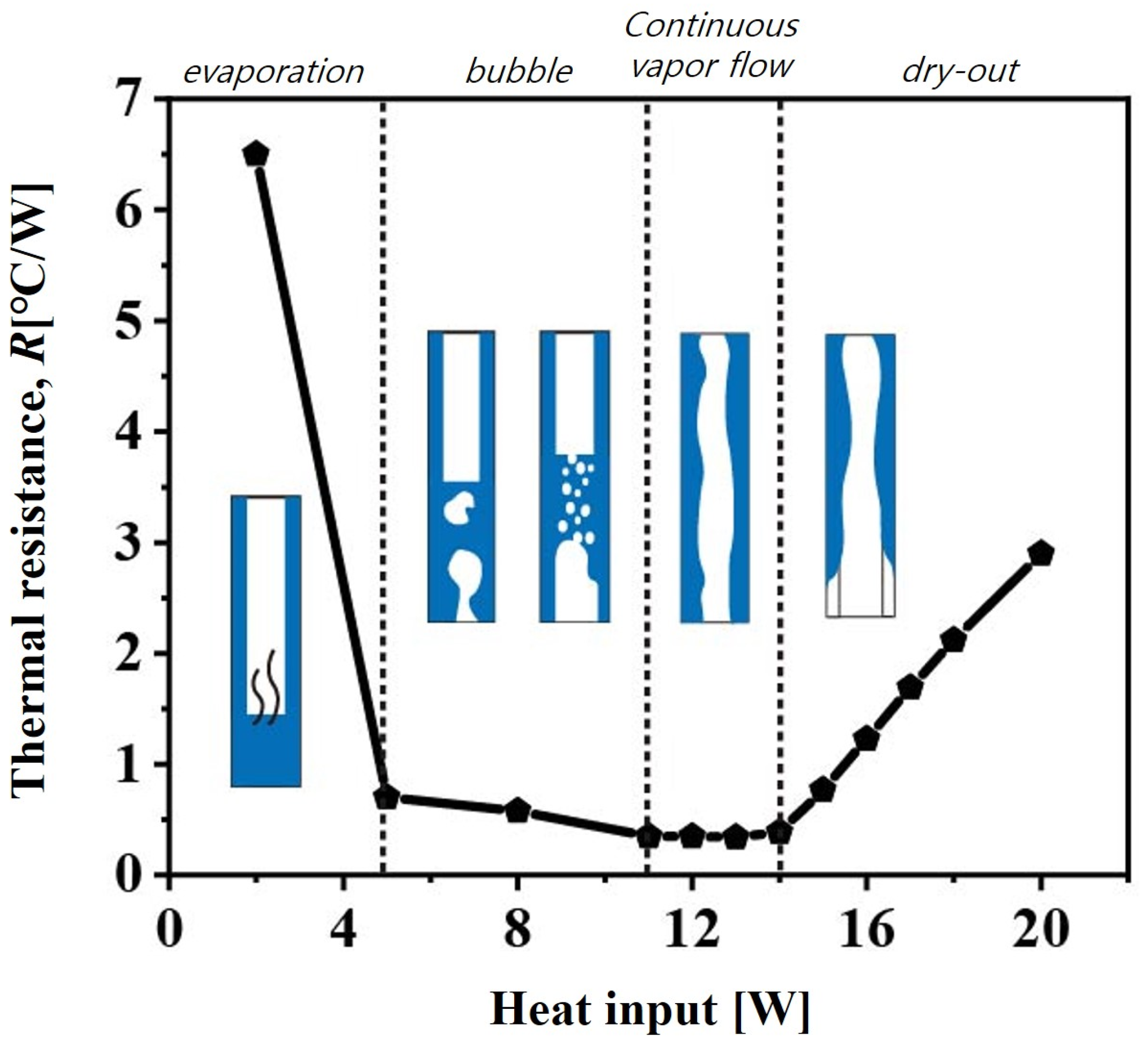
Figure 9 shows a schematic diagram illustrating the progressive change in a liquid-vapor state in a heat pipe. The heat pipe contains a wick with a thickness of 534.7 µm, which is made of 200 D powder. This transition proceeds as the temperature rises. During the initial stage, when the evaporation sector is being heated, the heat pipe exhibits a significant level of thermal resistance until the vapor is generated. Subsequently, despite a rise in temperature and the resulting generation of vapor in the evaporation sector, the presence of bubble blocks hinders the movement of vapor [16]. As the temperature rises, these bubble blocks disappear, thereby enabling the possibility of heat transfer.
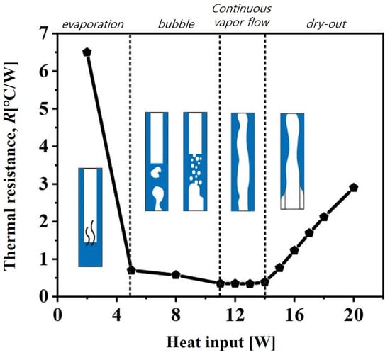
Figure 9.
Thermal resistance variation at different heating power input (tilting angle: 45°).
Afterwards, at a higher temperature, there is an increase in the amount of vapor accumulated in the condensation sector, while the amount of working fluid that need to be transported back to the evaporation sector through capillary force gradually decreases. In the case of a sustained rise in temperature, the working fluid in the evaporation sector becomes exhausted and the generation of evaporation-latent heat becomes impossible, leading to a dry-out state.
With an increase in the amount of working fluid, it is expected that the dry-out temperature will eventually increase. On the contrary, in order to achieve a low thermal resistance, it is essential to minimize the occurrence of initial bubble blockage caused by an excessive amount of working fluid. Therefore, it is necessary to maintain the working fluid at an appropriate level. The study observed that the optimal heat transfer capability was achieved when the level of working fluid was between 30–40%, which corresponds to results from previous studies [17,18,19,20].
3.4. Effect of the Tilling Angle on Heat Transfer Performance
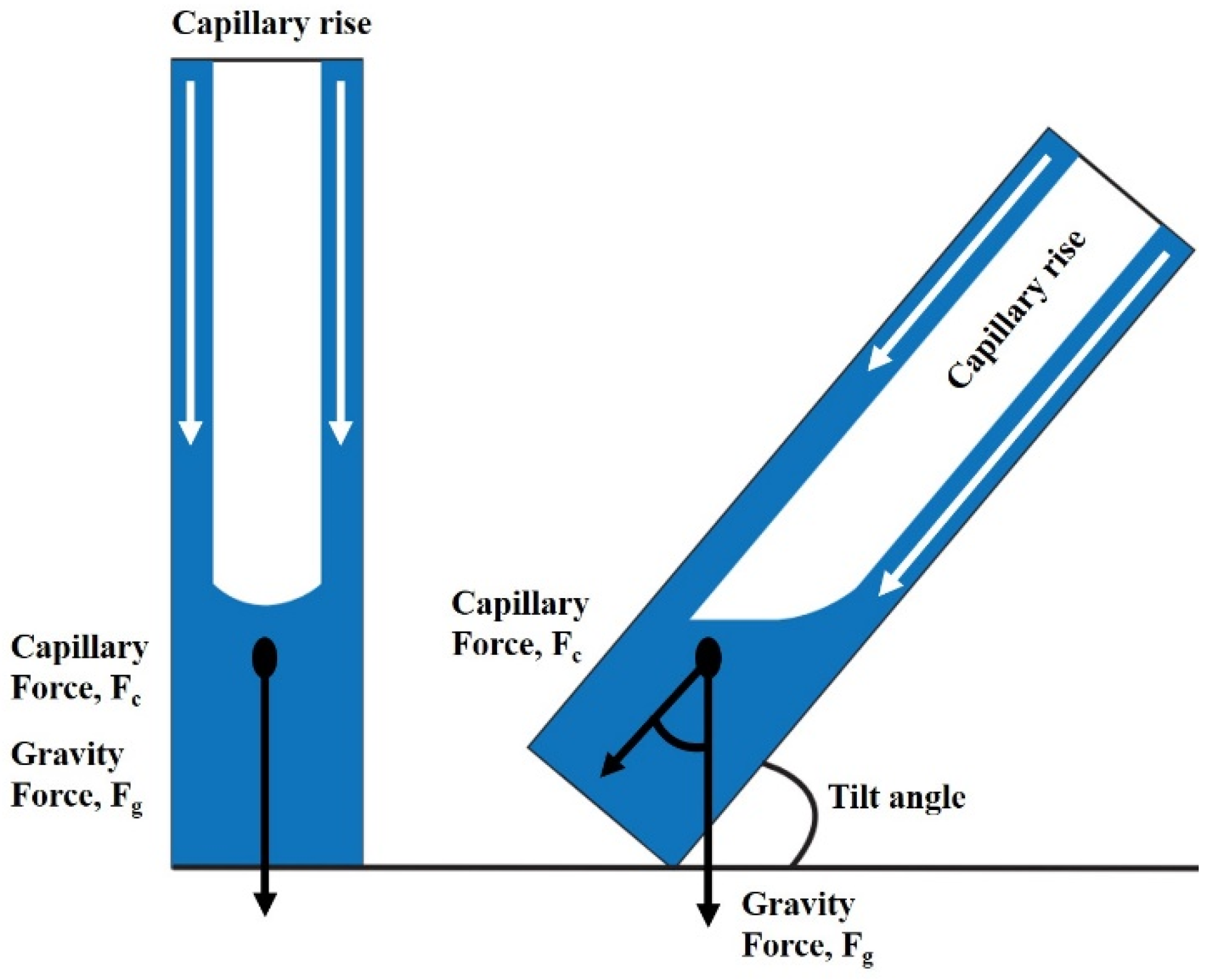
The comprehensive test results showed that there was an enhancement in heat transfer capability as the test angle (θ) increased from 0° to 90°, regardless of variations in powder type and wick thickness. This phenomenon can be attributed to the enhanced thermal distribution enabled by the gravity force, as well as the increased surface area of heat transfer, leading to higher cooling and heating capabilities. Figure 10 shows a schematic illustration of the phenomenon of capillary rise in a cylindrical tube, wherein the tilling angles are denoted by θ. The mathematical representation of the tilting angle requires the calculation of the cosine of the angle(θ) produced between two vectors. Hence, when the test angle reaches 90°, the alignment of capillary force and gravity occurs, leading to the enhanced movement of the liquid working fluid due to the resultant force. As the test angle approaches 0°, the relative alignment of capillary force and gravity undergoes a transition leading to a decrease in the value of cosθ and a reduction in the rate of the working fluid’s returning to the evaporator. In the situation of a horizontal orientation, the force of gravity is negated, thus enabling the controlled flow of the working fluid towards the evaporation unit. The decrease in pumping capacity causes a decrease in the ultimate operational threshold [21].

Figure 10.
A schematic of capillary rise in a cylindrical tube with tilling angles.
4. Conclusions
- (1)
- The heat pipe, which was equipped with a sintered wick made from 200 D powder, exhibited a smaller effective pore radius in comparison to 100 U. As a result, the utilization of 200 D powder resulted in an enhanced capillary force and exhibited improved efficacy in heat transfer.
- (2)
- The heat pipes’ wick thicknesses were measured as 902 μm, 534.7 μm, and 179.1 μm, which correspond to mandrel diameters of 1.5 mm, 2 mm, and 2.5 mm, respectively. The heat pipe with a wick thickness of 534.7 µm exhibited the most efficient heat transfer performance. The presence of a sufficient thickness of the wick ensures that an appropriate amount of working fluid is available to reach the region where evaporation takes place. Conversely, reducing the thickness of the wick results in a decrease in the amount of working fluid that can be retained in the wick, which can lead to dry-out, even when operating at low temperatures.
- (3)
- The initial thermal resistance value showed an increase as the filling ratio of the working fluid increased from 20 wt.% to 50 wt.%. Additionally, it was observed that the Qmax value exhibited a positive correlation with increasing temperature.
- (4)
- The heat transfer performance showed an enhancement as the tilting angles increased within the range of 0° to 90°. This can be attributed to the enhanced thermal distribution by the gravity force, as well as the expansion of the surface area for heat transfer due to the enlarged cooling and heating surfaces. Consequently, the heat resistance exhibits a low value, whereas the Qmax exhibits a high value.
Author Contributions
Methodology, I.-N.J.; Formal analysis, I.-N.J. and Y.-S.A.; Investigation, I.-N.J. and Y.-S.A.; Resources, Y.-S.A.; Data curation, I.-N.J.; Writing—original draft, I.-N.J. and Y.-S.A.; Writing—review & editing, Y.-S.A.; Visualization, I.-N.J.; Supervision, Y.-S.A.; Project administration, Y.-S.A.; Funding acquisition, Y.-S.A. All authors have read and agreed to the published version of the manuscript.
Funding
This research was financially supported by the Ministry of Trade, Industry, and Energy (MOTIE), Korea, under the “Development of a Cooling module for the Aircraft Data Transfer System (DTS)” program (reference number P150200002), supervised by the Korea Institute for Advancement of Technology (KIAT).
Data Availability Statement
All data are contained in the paper.
Conflicts of Interest
The authors declare no conflicts of interest.
References
- Kim, S.-D.; Kang, H.-K.; Sung, B.-H.; Kim, C.-J. In A Study on a Sintered Metal Wick Heat Pipe; Manufacturing and Inspection. In Proceedings of the KSME Conference, The Korean Society of Mechanical Engineers, Seoul, Republic of Korea, 20–22 April 2004; pp. 1487–1492. [Google Scholar]
- Lee, W.H.; Lee, K.W.; Park, K.H.; Lee, K.J.; Noh, S.Y. In Study on a Operating Characteristics of Loop Heat Pipe Using a Brass Sintered Metal Wick-Water. In Proceedings of the KSME Conference, The Korean Society of Mechanical Engineers, Seoul, Republic of Korea, 20–22 April 2004; pp. 1528–1533. [Google Scholar]
- Yun, H.G.; Moon, S.H.; Ko, S.C.; Hwang, G.; Choy, T.G. Manufacturing and operating performance of the heat pipe with sintered wick. Trans. Korean Soc. Mech. Eng. B 2002, 26, 1260–1266. [Google Scholar] [CrossRef]
- Jose, J.; Kumar Hotta, T. A comprehensive review of heat pipe: Its types, incorporation techniques, methods of analysis and applications. Therm. Sci. Eng. Prog. 2023, 42, 101860. [Google Scholar] [CrossRef]
- Jang, I.-N.; Ahn, Y.-S. The Study of Copper Powder Sintering for Porous Wick Structures with High Capillary Force. Materials 2023, 16, 4231. [Google Scholar] [CrossRef] [PubMed]
- Nezam, Z.Z.; Zohuri, B. Heat pipe as a passive cooling system driving new generation of nuclear power plants. Edelweiss Chem. Sci. J. 2020, 3, 326. [Google Scholar] [CrossRef]
- Nemec, P.; Čaja, A.; Malcho, M. Mathematical model for heat transfer limitations of heat pipe. Math. Comput. Model. 2013, 57, 126–136. [Google Scholar] [CrossRef]
- Reay, D.; McGlen, R.; Kew, P. Heat Pipes: Theory, Design and Applications; Butterworth-Heinemann: Oxford, UK, 2013. [Google Scholar]
- Jiang, L.-l.; Yong, T.; Wei, Z.; Jiang, L.-z.; Tan, X.; Yan, L.; Gao, J.-w. Design and fabrication of sintered wick for miniature cylindrical heat pipe. Trans. Nonferrous Met. Soc. China 2014, 24, 292–301. [Google Scholar] [CrossRef]
- Esmaeilzadeh, A.; Silakhori, M.; Nik Ghazali, N.N.; Metselaar, H.S.C.; Bin Mamat, A.; Naghavi Sanjani, M.S.; Iranmanesh, S. Thermal performance and numerical simulation of the 1-pyrene carboxylic-acid functionalized graphene nanofluids in a sintered wick heat pipe. Energies 2020, 13, 6542. [Google Scholar] [CrossRef]
- Park, S.-Y.; Boo, J.-H. An Experimental Study on the Heat Transfer Characteristics of High-Temperature Cylindrical Heat Pipes. Korean J. Air Cond. Refrig. Eng. 2004, 16, 70–76. [Google Scholar]
- Vasiliev, L. Micro and miniature heat pipes–Electronic component coolers. J Appl. Therm. Eng. 2008, 28, 266–273. [Google Scholar] [CrossRef]
- Li, Y.; He, J.; He, H.; Yan, Y.; Zeng, Z.; Li, B. Investigation of ultra-thin flattened heat pipes with sintered wick structure. Appl. Therm. Eng. 2015, 86, 106–118. [Google Scholar] [CrossRef]
- Liao, X.; Jian, Q.; Zu, S.; Li, D.; Huang, Z. Visualization study and analysis on the heat transfer performance of an ultra-thin flat-plate heat pipe. Int. Commun. Heat Mass Transf. 2021, 126, 105464. [Google Scholar] [CrossRef]
- STM32H743 Datasheet. STM32H742xI/G STM32H743xI/G. 2019. Available online: https://www.alldatasheet.com/datasheet-pdf/pdf/1179094/STMICROELECTRONICS/STM32H743.html (accessed on 1 December 2023).
- Ilić, M.; Petrović, M.M.; Stevanović, V. Boiling heat transfer modelling a review and future prospectus. Therm. Sci. 2019, 23, 87–107. [Google Scholar] [CrossRef]
- Chang, C.; Han, Z.; He, X.; Wang, Z.; Ji, Y. 3D printed aluminum flat heat pipes with micro grooves for efficient thermal management of high power LEDs. Sci. Rep. 2021, 11, 8255. [Google Scholar] [CrossRef] [PubMed]
- Manimaran, R.; Palaniradja, K.; Alagumurthi, N.; Velmurugan, K. An investigation of thermal performance of heat pipe using Di-water. Sci. Technol. 2012, 2, 77–80. [Google Scholar] [CrossRef]
- Wang, G.; Quan, Z.; Zhao, Y.; Wang, H. Performance of a flat-plate micro heat pipe at different filling ratios and working fluids. Appl. Therm. Eng. 2019, 146, 459–468. [Google Scholar] [CrossRef]
- Zhou, J.; Liu, L.; Yang, X.; Zhang, Y.; Wei, J. Visualization research on influencing factors of flat heat pipes. Appl. Therm. Eng. 2022, 207, 118193. [Google Scholar] [CrossRef]
- Bamorovat Abadi, G.; Bahrami, M. A general form of capillary rise equation in micro-grooves. Sci. Rep. 2020, 10, 19709. [Google Scholar] [CrossRef] [PubMed]
Disclaimer/Publisher’s Note: The statements, opinions and data contained in all publications are solely those of the individual author(s) and contributor(s) and not of MDPI and/or the editor(s). MDPI and/or the editor(s) disclaim responsibility for any injury to people or property resulting from any ideas, methods, instructions or products referred to in the content. |
© 2024 by the authors. Licensee MDPI, Basel, Switzerland. This article is an open access article distributed under the terms and conditions of the Creative Commons Attribution (CC BY) license (https://creativecommons.org/licenses/by/4.0/).