

Evaluation of a New Droplet Growth Model for Small Droplets in Condensing Steam Flows

 ,
,  , ,
, , 
Abstract
1. Introduction
2. Physical and Numerical Model
2.1. Condensation Model
2.1.1. Continuous Model
2.1.2. Kinetic Model
2.1.3. Proposed Model
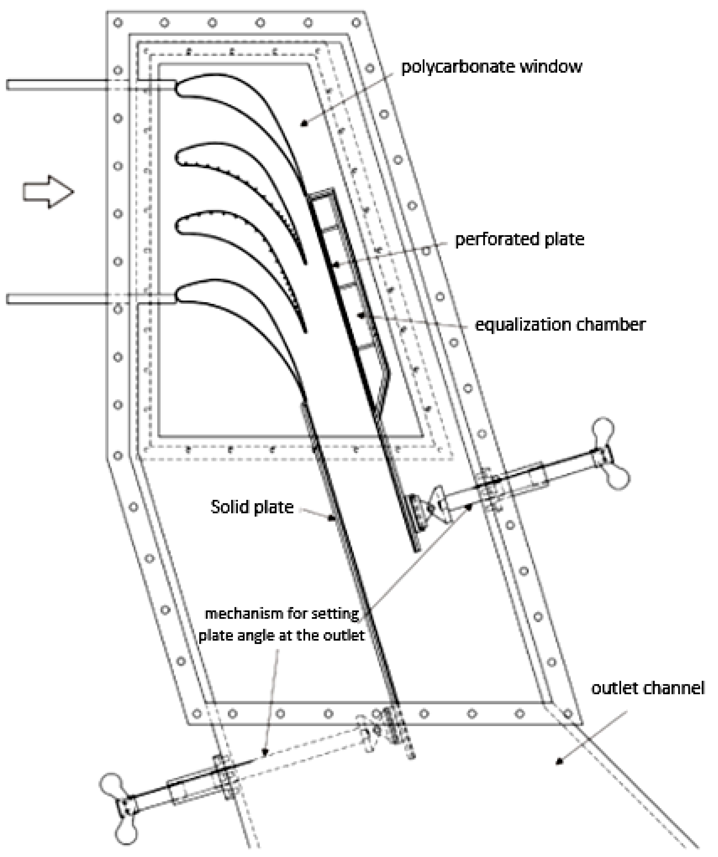
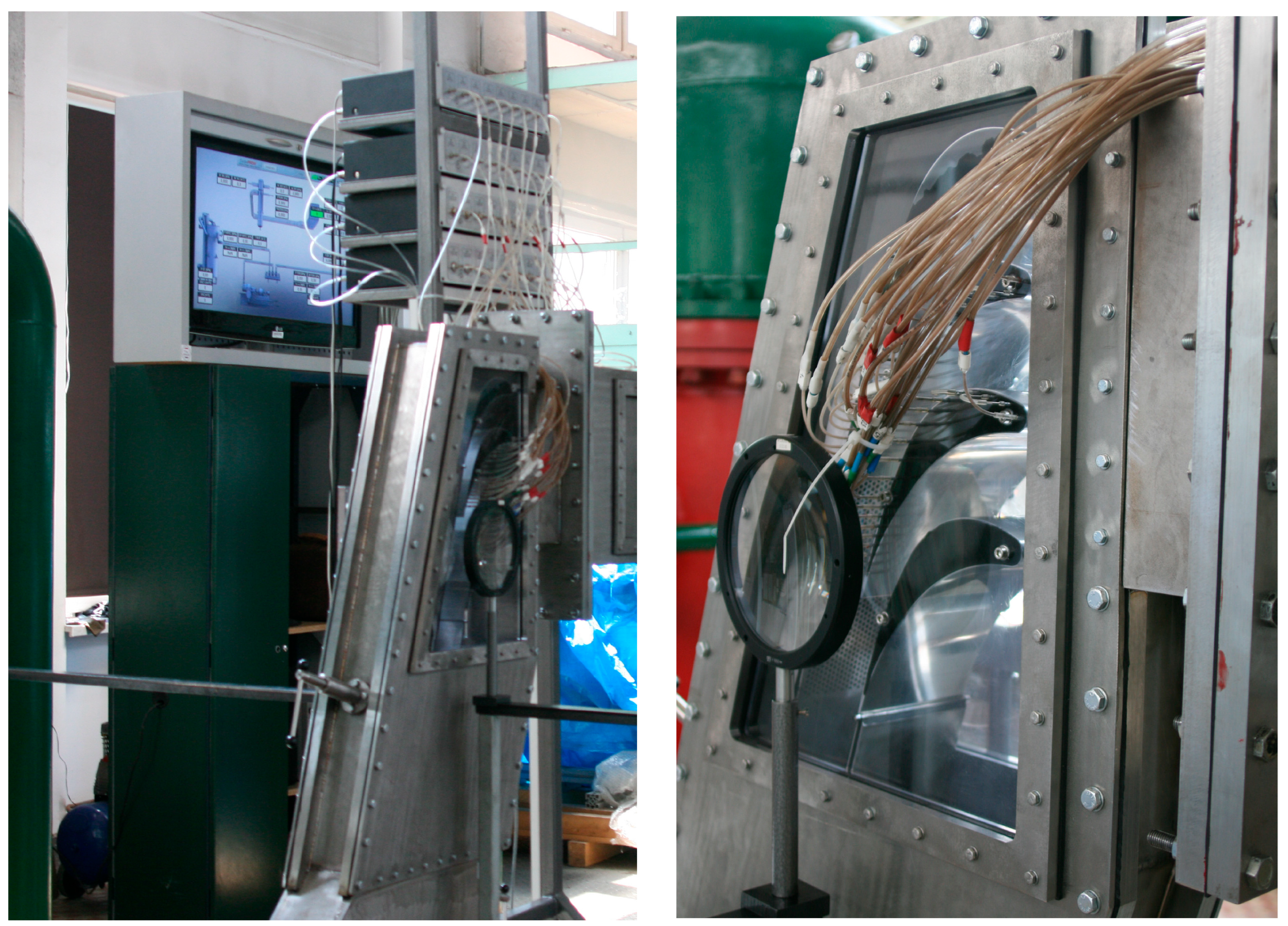
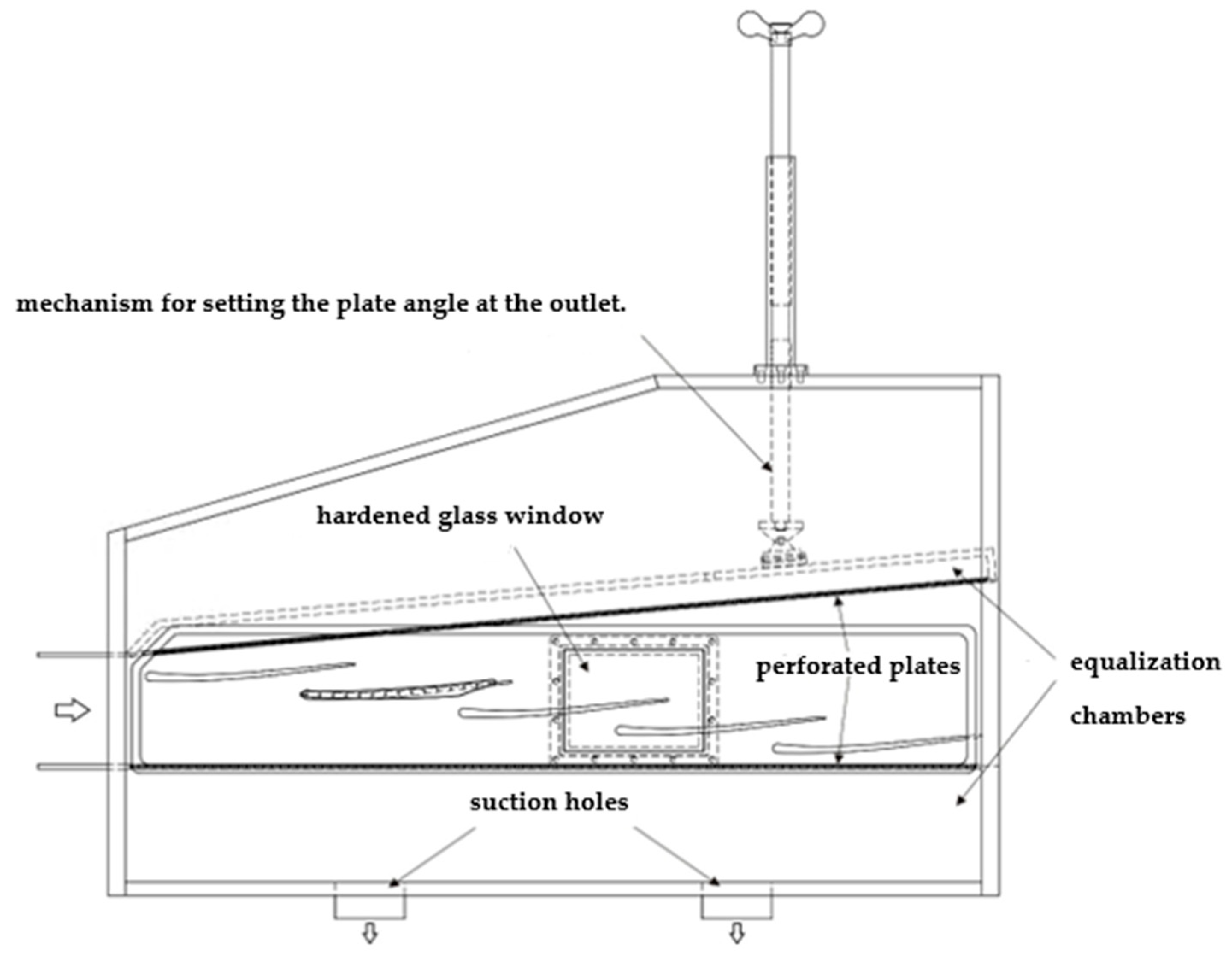
3. Experimental Test Rig and Boundary Conditions
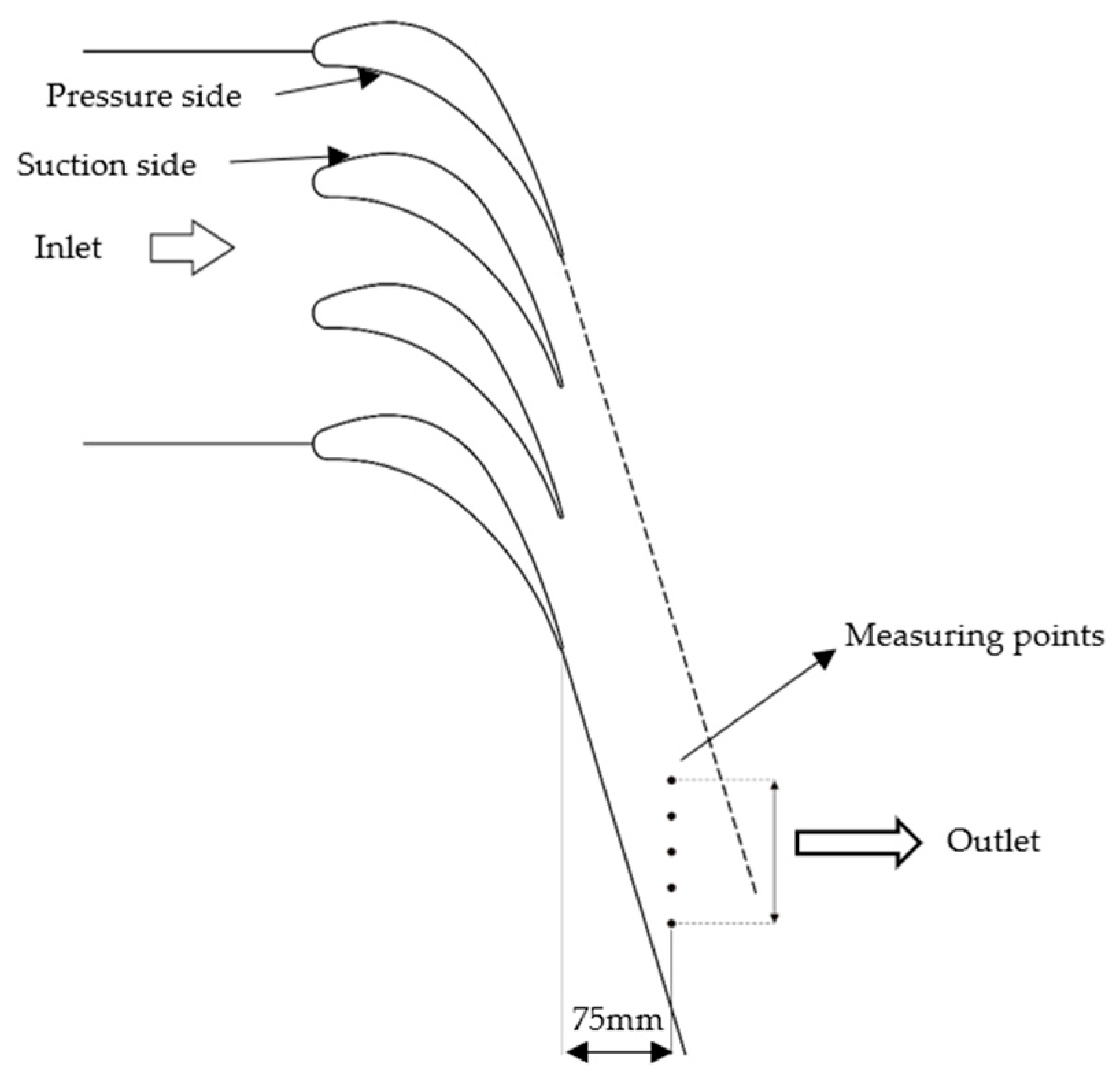
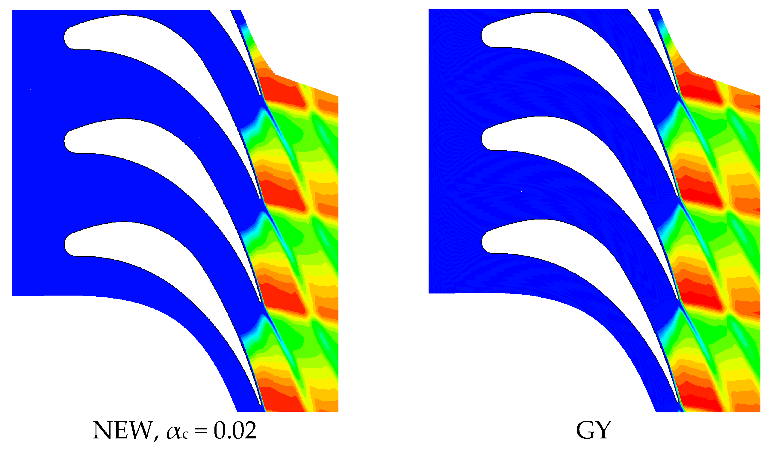
3.1. Linear Stator Blade Cascades
- Blade chord in axial direction: 173.97 mm;
- Pitch: 91.74 mm;
- Working medium inflow angle: 0.0°;
- Test section width: 110 mm.
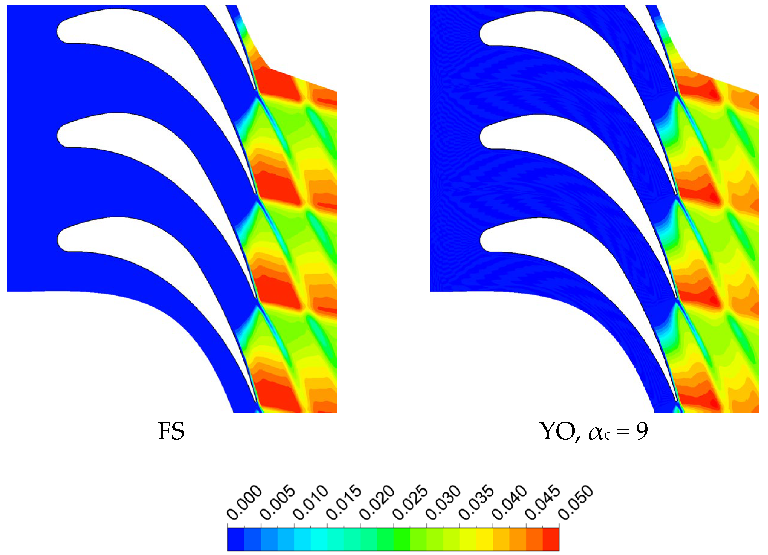
3.2. Linear Rotor Blade Cascades
- Blade chord in axial direction: 240.17 mm;
- Pitch: 180 mm;
- Working medium inflow angle: 0.0°;
- Test section width: 110 mm.
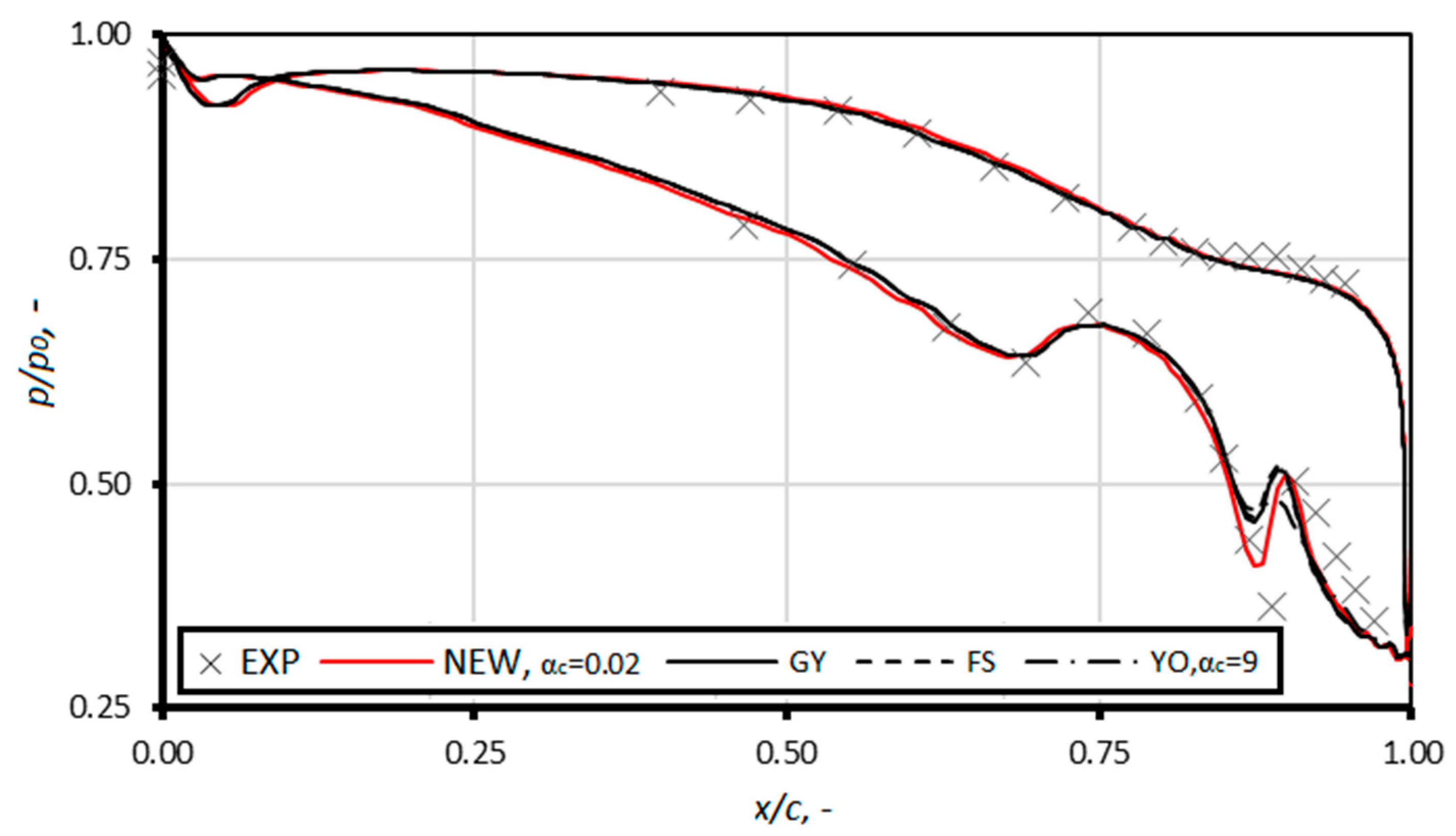
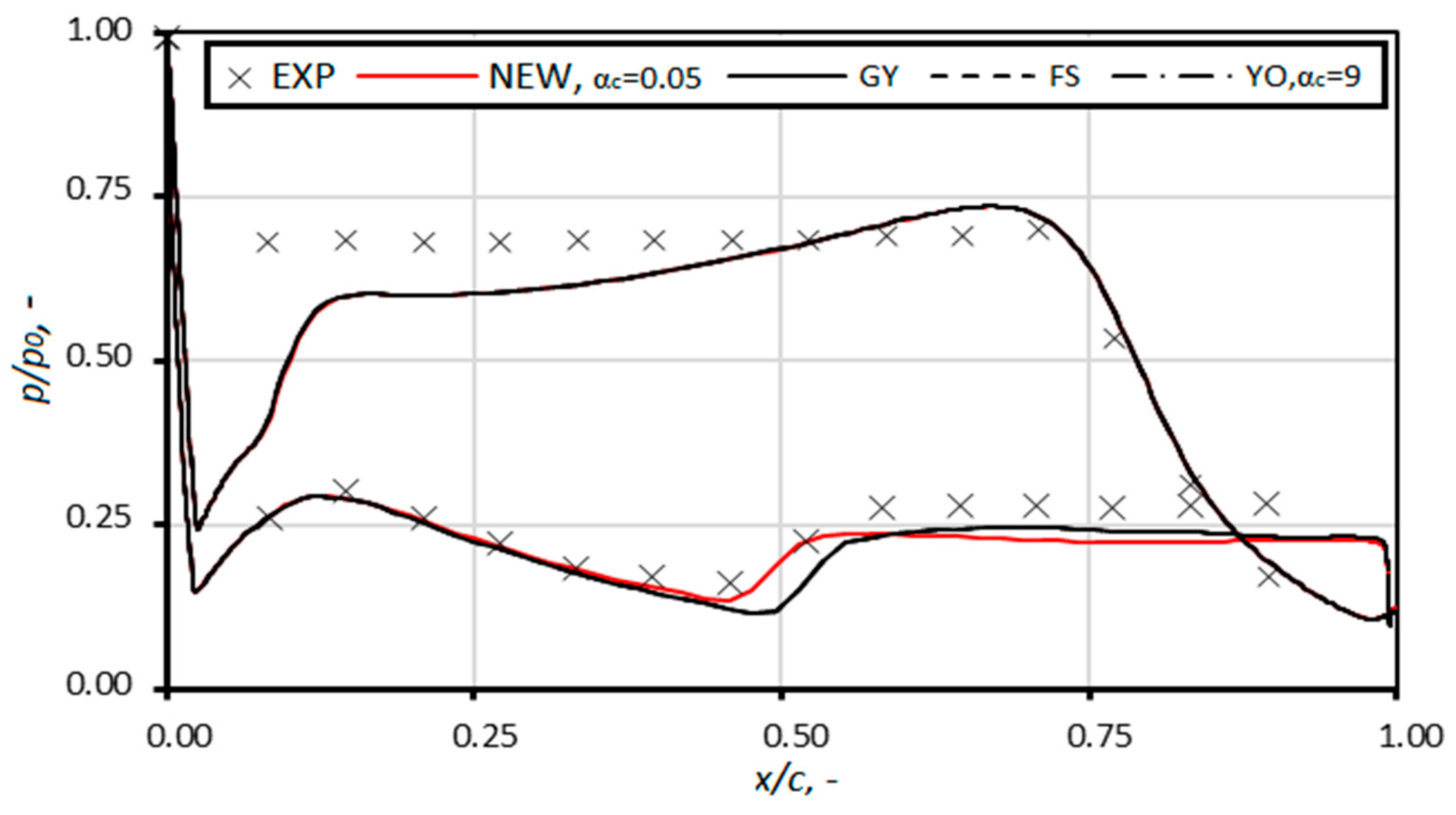
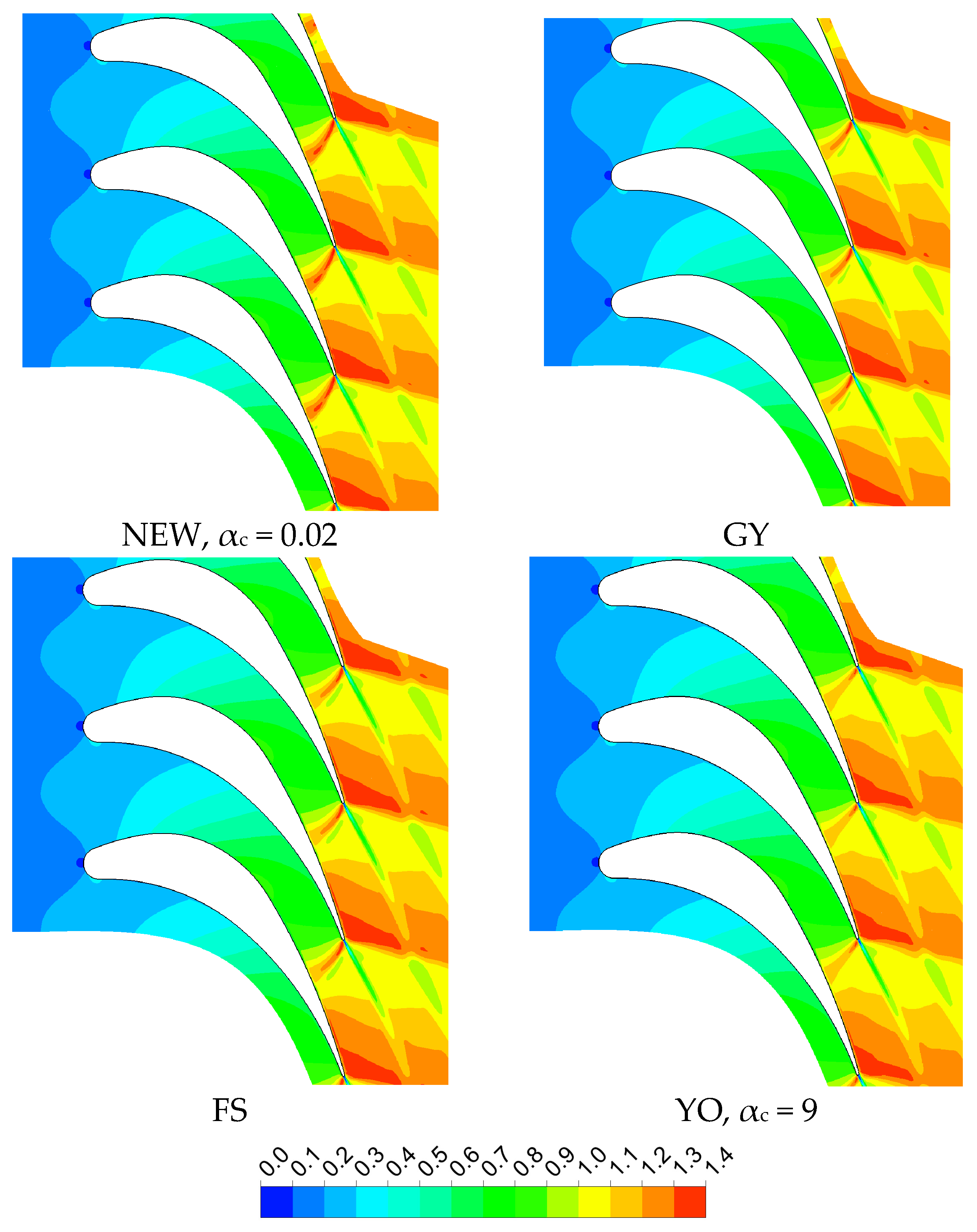
4. Results and Discussion
5. Conclusions
Author Contributions
Funding
Data Availability Statement
Conflicts of Interest
Nomenclature
| cv | Specific heat in constant volume, J kg−1K−1 |
| cp | Specific heat in constant pressure, J kg−1K−1 |
| E | Total internal energy, J kg−1 |
| J | Nucleation rate, m−3s−1 |
| kB | Boltzmann constant, J K−1 |
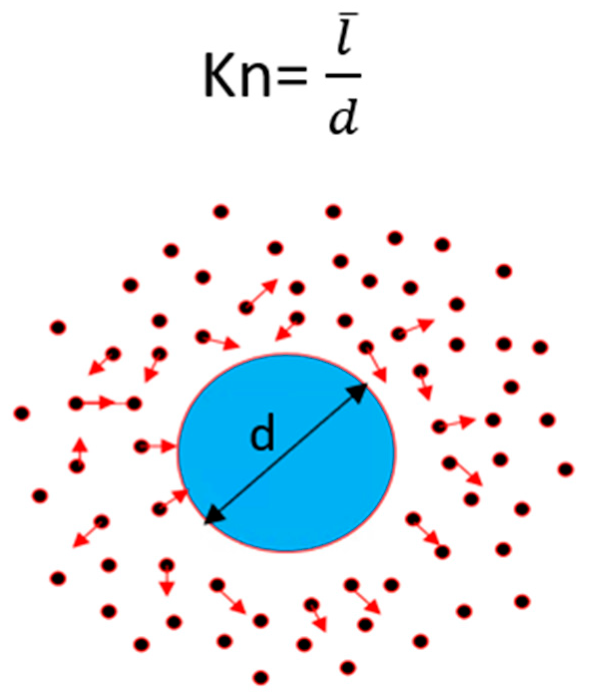
| Kn | Knudsen number, |
| Mean free path | |
| L | Latent heat, J kg−1 |
| m | Molecular mass, kg |
| n | Number of droplets, m−3 |
| Nu | Nusselt number |
| p | Pressure, pa |
| Pr | Prandtl number |
| r | Droplet radius, m |
| r* | Critical droplet radius, m |
| R | Gas constant, J kg−1K−1 |
| S | Supersaturation ratio, |
| T | Temperature, K |
| t | Time, s |
| u | Velocity vector, m s−1 |
| x | Axial coordinate, m |
| y | Wetness fraction |
| Greek symbols | |
| α | Heat transfer coefficient |
| αc | Condensation coefficient |
| γ | Ratio of specific heat |
| δ | Kronecker delta |
| λ | Thermal conductivity, W m−1K−1 |
| Density, kg m−3 | |
| σ | Surface tension, N m−1 |
| τ | Stress tensor, Pa |
| Subscripts | |
| l | Liquid |
| s | Saturation |
| v | Vapor |
References
- Yousefi Rad, E.; Mahpeykar, M.R. A Novel Hybrid Approach for Numerical Modeling of the Nucleating Flow in Laval Nozzle and Transonic Steam Turbine Blades. Energies 2017, 10, 1285. [Google Scholar] [CrossRef]
- Fan, S.; Wang, Y.; Yao, K.; Shi, J.; Han, J.; Wan, J. Distribution Characteristics of High Wetness Loss Area in the Last Two Stages of Steam Turbine under Varying Conditions. Energies 2022, 15, 2527. [Google Scholar] [CrossRef]
- Lakzian, E.; Ramezani, M.; Shabani, S.; Salmani, F.; Majkut, M.; Kim, H.D. The search for an appropriate condensation model to simulate wet steam transonic flows. Int. J. Numer. Methods Heat Fluid Flow 2023, 33, 2853–2876. [Google Scholar] [CrossRef]
- Halama, J.; Fořt, J. Numerical simulation of transonic flow of wet steam in nozzles and turbines. Computing 2013, 95, 303–318. [Google Scholar] [CrossRef]
- Ihm, S.W.; Kim, C. Computations of homogeneous equilibrium two-phase flows with accurate and efficient shock-stable schemes. AIAA 2008, 46, 3012–3037. [Google Scholar] [CrossRef]
- Grübel, M.; Starzmann, J.; Schatz, M.; Eberle, T.; Vogt, D.M.; Sieverding, F. Two-phase flow modeling and measurements in low-pressure turbines: Part 1—Numerical validation of wet steam models and turbine modeling. Trans. ASME J. Eng. Gas Turbines Power 2015, 137, 042602. [Google Scholar] [CrossRef]
- Yamamoto, S.; Daiguji, H. Higher-order-accurate upwind schemes for solving the compressible Euler and Navier-stokes equations. Comput. Fluids 1993, 22, 259–270. [Google Scholar] [CrossRef]
- Mirafiori, M.; Tancon, M.; Bortolin, S.; Del Col, D. Modeling of growth and dynamics of droplets during dropwise condensation of steam. Int. J. Heat Mass Transf. 2024, 222, 125109. [Google Scholar] [CrossRef]
- Sidin, R.S.R.; Hagmeijer, R.; Sachs, U. Evaluation of master equations for the droplet size distribution in condensing flow. Phys. Fluids 2009, 21, 073303. [Google Scholar] [CrossRef]
- Shabani, S.; Majkut, M.; Dykas, S.; Smołka, K.; Lakzian, E.; Zhang, G. Validation of the CFD Tools against In-House Experiments for Predicting Condensing Steam Flows in Nozzles. Energies 2023, 16, 4690. [Google Scholar] [CrossRef]
- Guo, Y.; Wang, R.; Zhao, D.; Gong, L.; Shen, S. Numerical Simulation of Vapor Dropwise Condensation Process and Droplet Growth Mode. Energies 2023, 16, 2442. [Google Scholar] [CrossRef]
- Peeters, P.; Luijten, C.C.M.; van Dongen, M.E.H. Transitional droplet growth and diffusion coefficients. Int. J. Heat Mass Transf. 2001, 44, 181–193. [Google Scholar] [CrossRef]
- Shabani, S.; Majkut, M.; Dykas, S.; Wiśniewski, P.; Smołka, K.; Cai, X.; Zhang, G. Numerical analysis of the condensing steam flow by means of ANSYS Fluent and in-house academic codes with respect to the capacity for thermodynamic assessment. Front. Energy Res. 2022, 10, 902629. [Google Scholar] [CrossRef]
- Ezhova, E.; Kerminen, V.; Lehtinen, K.; Kulmala, M. A simple model for the time evolution of the condensation sink in the atmosphere for intermediate Knudsen numbers. Atmos. Chem. Phys. 2018, 18, 2431–2442. [Google Scholar] [CrossRef]
- Chandler, K.D.; White, A.J.; Young, J.B. Non-equilibrium wet-steam calculations of unsteady low-pressure turbine flows. Proc. IMechE Part A J. Power Energy 2014, 228, 143–152. [Google Scholar] [CrossRef]
- Pathak, H.; Mullick, K.; Tanimura, S.; Wyslouzil, B. Nonisothermal Droplet Growth in the Free Molecular Regime. Aerosol Sci. Technol. 2013, 47, 1310–1324. [Google Scholar] [CrossRef]
- Puzyrewski, R.; Studzinski, W. One-dimensional water vapor expansion with condensation at higher pressures. Int. J. Multiph. Flow 1980, 6, 425–439. [Google Scholar] [CrossRef]
- Puzyrewski, R.; Król, T. Numerical analysis of Hertz-Knudsen model of condensation upon small droplets in water vapor. IFFM 1976, 70, 285–307. [Google Scholar]
- Han, X.; Han, Z.; Zeng, W.; Quan, J.; Wang, Z. Coupled Model of Heat and Mass Balance for Droplet Growth in Wet Steam Non-Equilibrium Homogeneous Condensation Flow. Energies 2017, 10, 2033. [Google Scholar] [CrossRef]
- Sun, W.; Chen, S.; Hou, Y.; Bu, S.; Ma, Z.; Zhang, L. Numerical Studies of Nitrogen Spontaneous Condensation Flow in Laval Nozzles using Varying Droplet Growth Models. Int. J. Multiph. Flow 2019, 121, 103118. [Google Scholar] [CrossRef]
- Zhang, G.; Zhang, X.; Wang, D.; Jin, Z.; Qin, X. Performance evaluation and operation optimization of the steam ejector based on modified model. Appl. Therm. Eng. 2019, 163, 114388. [Google Scholar] [CrossRef]
- Zhang, G.; Dykas, S.; Yang, S.; Zhang, X.; Li, H.; Wang, J. Optimization of the primary nozzle based on a modified condensation model in a steam ejector. Appl. Therm. Eng. 2020, 171, 115090. [Google Scholar] [CrossRef]
- Wiśniewski, P.; Majkut, M.; Dykas, S.; Smołka, K.; Zhang, G.; Pritz, B. Selection of a steam condensation model for atmospheric air transonic flow prediction. Appl. Therm. Eng. 2022, 203, 117922. [Google Scholar] [CrossRef]
- Bakhtar, F.; Young, J.B.; White, A.J.; Simpson, D.A. Classical Nucleation Theory and Its Application to Condensing Steam Flow Calculations. Proc. Inst. Mech. Eng. Part C J. Mech. Eng. Sci. 2005, 219, 1315–1333. [Google Scholar] [CrossRef]
- Shabani, S.; Majkut, M.; Dykas, S.; Smołka, K.; Lakzian, E. An investigation comparing various numerical approaches for simulating the behaviour of condensing flows in steam nozzles and turbine cascades. Eng. Anal. Bound. Elem. 2024, 158, 364–374. [Google Scholar] [CrossRef]
- Hill, P.G. Condensation of water vapour during supersonic expansion in nozzle. J. Fluid Mech. 1966, 25, 593–620. [Google Scholar] [CrossRef]
- Dykas, S.; Majkut, M.; Strozik, M.; Smołka, K. Losses Estimation in Transonic Wet Steam Flow through Linear Blade Cascade. J. Therm. Sci. 2015, 24, 109–116. [Google Scholar] [CrossRef]
- Dykas, S.; Majkut, M.; Smołka, K.; Strozik, M. Study of the wet steam flow in the blade tip rotor linear blade cascade. Int. J. Heat Mass Transf. 2018, 120, 9–17. [Google Scholar] [CrossRef]


| Stator | Rotor | |
|---|---|---|
| Inlet | P0 = 103 kPa T0 = 105.85 °C | P0 = 65 kPa T0 = 130.5 °C |
| Outlet | Pout = 42 kPa | Pout = 14 kPa |
Disclaimer/Publisher’s Note: The statements, opinions and data contained in all publications are solely those of the individual author(s) and contributor(s) and not of MDPI and/or the editor(s). MDPI and/or the editor(s) disclaim responsibility for any injury to people or property resulting from any ideas, methods, instructions or products referred to in the content. |
© 2024 by the authors. Licensee MDPI, Basel, Switzerland. This article is an open access article distributed under the terms and conditions of the Creative Commons Attribution (CC BY) license (https://creativecommons.org/licenses/by/4.0/).
Share and Cite
Shabani, S.; Majkut, M.; Dykas, S.; Smołka, K.; Lakzian, E.; Ghodrati, M.; Zhang, G. Evaluation of a New Droplet Growth Model for Small Droplets in Condensing Steam Flows. Energies 2024, 17, 1135. https://doi.org/10.3390/en17051135
Shabani S, Majkut M, Dykas S, Smołka K, Lakzian E, Ghodrati M, Zhang G. Evaluation of a New Droplet Growth Model for Small Droplets in Condensing Steam Flows. Energies. 2024; 17(5):1135. https://doi.org/10.3390/en17051135
Chicago/Turabian StyleShabani, Sima, Mirosław Majkut, Sławomir Dykas, Krystian Smołka, Esmail Lakzian, Mohammad Ghodrati, and Guojie Zhang. 2024. "Evaluation of a New Droplet Growth Model for Small Droplets in Condensing Steam Flows" Energies 17, no. 5: 1135. https://doi.org/10.3390/en17051135
APA StyleShabani, S., Majkut, M., Dykas, S., Smołka, K., Lakzian, E., Ghodrati, M., & Zhang, G. (2024). Evaluation of a New Droplet Growth Model for Small Droplets in Condensing Steam Flows. Energies, 17(5), 1135. https://doi.org/10.3390/en17051135