Abstract
The voltage source converter-based multi-terminal DC transmission (VSC-MTDC) system can use additional frequency control to respond to the frequency change of faulty AC system. However, the control coefficient of traditional additional frequency control is mostly fixed, and the control flexibility is insufficient, so it cannot be adjusted adaptively according to the frequency change of the system. Therefore, a frequency control strategy of the VSC-MTDC system based on fuzzy logic control is proposed. Based on the DC voltage slope controller, this strategy introduces an additional frequency controller based on fuzzy logic control, takes the frequency deviation and frequency change rate as the additional controller input, and dynamically adjusts the control quantity through the fuzzy logic control link to realize the adaptive adjustment of the VSC-MTDC system to the AC system’s frequency. Finally, a three-terminal flexible HVDC system is built on the PSCAD/EMTDC simulation platform for simulation verification. The results show that the proposed control strategy can effectively use the flexible DC system to support the frequency of the AC system and significantly improve the frequency stability of the faulty AC system.
1. Introduction
Compared with the traditional line-commutated converter-based high-voltage DC transmission (LCC-HVDC) system, the VSC-MTDC system can achieve independent control of active power and reactive power without commutation failure. With the increase of power grid scale and the increasing demand for interconnection between different regional power grids, the interconnection mode based on the VSC-MTDC system has been widely used [1,2]. With the increasing proportion of wind power, photovoltaic and other new energy in the power system, the frequency stability of AC/DC power system will also face greater challenges [3,4,5]. The control flexibility of the multi-terminal flexible DC transmission system makes it have obvious advantages in realizing power interaction and frequency support among multiple long-distance AC power grids. By adding frequency control to the control strategy of the VSC-MTDC system, the frequency stability of the faulty AC system can be effectively improved [6].
At present, the power coordinated control mode of the VSC-MTDC system’s power-coordinated control is mainly divided into master–slave control, margin control, and droop control [7]. The master–slave control ensures the system balance by controlling the DC voltage and transmission power of the flexible DC system, respectively. The control mode is simple, but only the master station of the converter station can bear the system power fluctuation, and inter-station communication is needed. Compared with the master–slave control, the margin control presets several voltage control master stations, which can realize the hierarchical control of the system voltage, but the control mode is more complex, and the voltage margin setting is more difficult. Compared with the above control methods, droop control can achieve power unbalance shared by multiple converter stations, and does not need inter-station communication, so it has been widely used in VSC-MTDC-coordinated control.
Under the traditional droop control mode, when the frequency change is caused by the failure of an AC system, the converter station of the VSC-MTDC system cannot respond to the frequency change, and the frequency stability can only depend on the faulty AC system [8]. On the basis of the traditional droop control, the frequency variation is superimposed on the reference value of the droop control of the converter station in the VSC-MTDC system to urge the converter station to participate in the frequency regulation of the system. Compared with reference [9], reference [10] introduces the running dead zone in the additional frequency control link, which can avoid the frequent trigger of the control while responding to the frequency of the AC system and improve the stability of the system to a certain extent. However, the effect of frequency change rate on system frequency modulation is not taken into account. In reference [11], the frequency of the faulty AC system is adjusted by using inter-station communication, taking the difference of frequency difference and frequency change rate of different AC systems as control reference values.
References [12,13] combine additional frequency control with virtual synchronous control technology to adjust the frequency of the AC system under the condition of controlling frequency deviation and frequency change rate at the same time. A droop control method, which can adjust the frequency adaptively, is proposed in reference [14]. This method adjusts the DC voltage droop coefficient in real time according to the frequency deviation of the AC system, so that the converter stations does not need to communicate between stations, which quickly adjust their output power to ensure the frequency stability of the AC system. Considering the problem of low inertia of the power system in reference [15], P-f droop control is added to the converter control system to realize the adaptive control of the VSC-MTDC system, which can quickly adjust the active power balance and reduce the DC voltage fluctuation by using the converter capacity to a greater extent. For practical power systems, time delay is an important issue to be studied. Reference [16] proposes a delay-kernel-dependent approach to deal with the saturated control problem. By combining the state vector and the distributed delay with kernel, a new polytopic representation strategy is used to cope with the nonlinear input saturation function. Reference [17] proposes an event-triggered fuzzy load frequency control strategy for wind power systems with measurement outliers and transmission delays. The time delay of the control signal is considered in reference [16,17], which makes the control system more practical and stable.
The above method makes use of the control flexibility of the converter station, realizes the effective support of the DC system to the AC system frequency, and improves the frequency stability of the system to a certain extent. However, most of the existing control methods do not consider the robustness and adaptability of the converter station control system and have strong sensitivity to the change of frequency parameters, resulting in the lack of anti-interference ability of the system. To solve the above problems, a frequency control strategy of the VSC-MTDC system based on fuzzy logic control is proposed in this paper. Firstly, the basic principle of power control of the VSC-MTDC system is analyzed. Secondly, based on the DC voltage slope controller, the additional frequency controller is introduced, and the controller structure is designed based on the fuzzy logic control principle. Taking the frequency deviation and frequency change rate as inputs, considering the robustness and adaptability of the control system, the fuzzy logic control link is used to dynamically adjust the control quantity to realize the VSC-MTDC system to dynamically adjust the frequency of the faulty AC system. Finally, the effectiveness and superiority of the proposed control strategy are verified by building a three-terminal flexible HVDC system.
2. Traditional Power Control Principle of VSC-MTDC System
The VSC-MTDC system is a DC system with three or more voltage source converter stations. According to the requirements of actual operating conditions, VSC-MTDC systems are usually divided into three connection modes: series type, parallel type, and hybrid type. In contrast, the parallel VSC-MTDC system has the characteristics of strong expansibility, high flexibility, and low line loss, so it has been widely used.
The traditional VSC-MTDC system generally adopts the fixed active power control method, and there is no communication between the converter stations. When one of the AC systems fails or the load changes, the converter station cannot respond in time, and the power unbalance can only be borne by the faulty AC system; moreover, the rest of the AC systems cannot be supported by power. Although the fixed active power control method has certain advantages in isolating the interaction between AC systems, it sacrifices the ability of mutual support between AC systems, which is not conducive to the stable operation of the system.
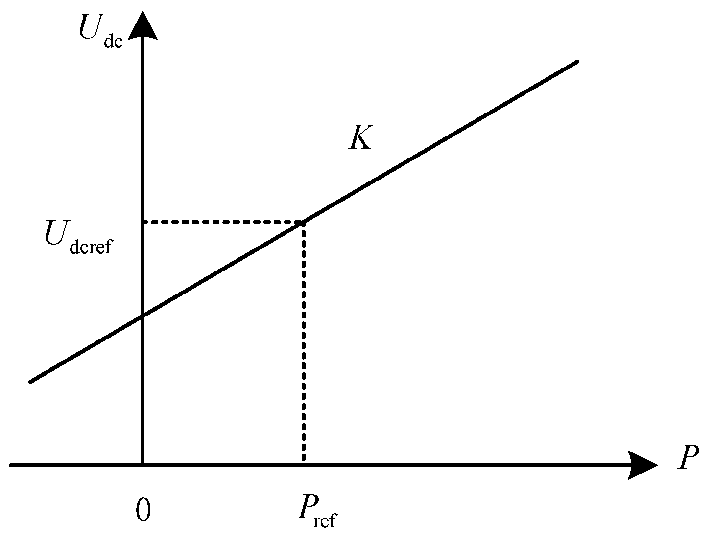
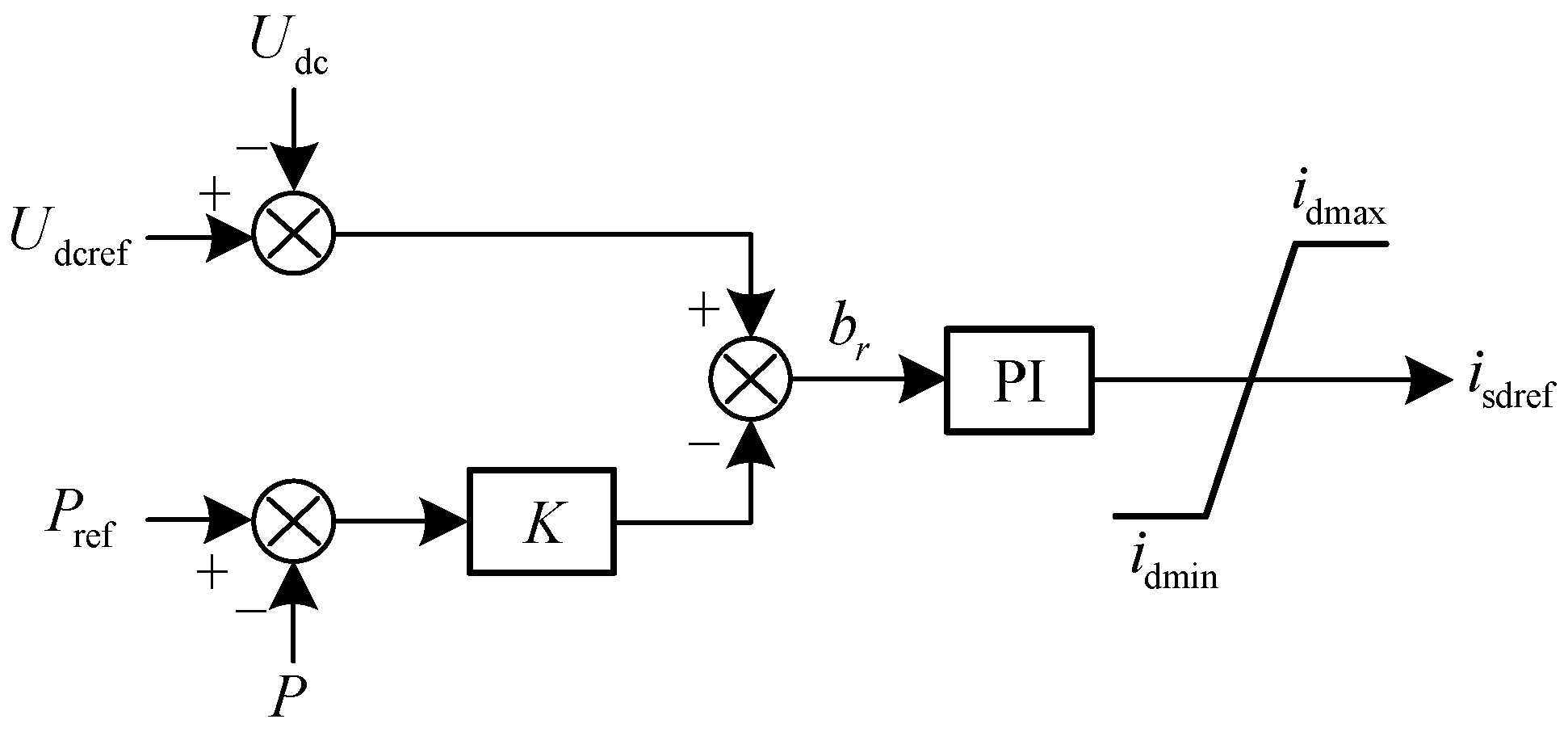
By adopting the constant DC voltage slope control strategy in the VSC-MTDC system, the frequency stability of the faulty AC system can be effectively improved. The control idea of the constant DC voltage slope control strategy comes from the frequency modulation controller in the AC system, which can be expressed by a curve of the relationship between DC voltage and power. The control characteristics and controller structure are shown in Figure 1 and Figure 2, respectively.

Figure 1.
Constant DC voltage slope control characteristics.

Figure 2.
Constant DC voltage slope control block diagram.
In the figure, Pref represents the active power instruction value; Udcref represents the DC voltage instruction value; K represents the slope of P-Udc; and br represents the DC voltage deviation, which is close to zero in steady state. isdref is the reference value of the control current of the converter station; idmax and idmin are the upper limit and the lower limit of the control current, respectively. The constant DC voltage slope controller combines the characteristics of the power controller and the DC voltage controller. Its purpose is to realize the balance of the transmission power of the DC network while controlling the input AC power of the converter station. Formula (1) can be obtained from Figure 1.
When the VSC-MTDC system is disturbed, the unbalanced power generated is . If the system is composed of N converter stations, the stable operating point of the nth converter station changes from to . If is defined, the corresponding DC voltage change is
Unbalanced power can be expressed as
It is known from Formula (2) that
It is known from Formula (3) that
Therefore, it can be concluded that the power shared by the converter station with a slope of is
It can be seen from Formula (4) that the unbalanced power borne by the converter station is mainly determined by K. When K is larger, the unbalanced power borne by the corresponding converter station is smaller, and vice versa, so slope K is usually inversely proportional to the capacity of the converter. The constant DC voltage slope control strategy does not require communication between stations, and the converter stations with power regulation ability will adjust the power according to the measured DC voltage according to slope K and share the unbalanced power in the system. It can improve the stability of the system to a certain extent. However, it is unable to respond to the frequency deviation and frequency change rate of the AC system, and the frequency modulation capacity is very limited, so it is necessary to study more effective control strategies.
3. Frequency Stability Control Strategy of VSC-MTDC System Based on Fuzzy Logic Control
Although the constant DC voltage slope control strategy enables multiple converters to participate in the regulation of the unbalanced power of the DC network—reducing the impact on the AC system connected to a single dominant converter station—only constant DC voltage slope control cannot respond to the frequency change of the AC system, the frequency of the faulty AC system can only rely on its own frequency modulation capability, and the rest of the AC system cannot be supported by power. Therefore, a frequency stability control strategy of the VSC-MTDC system based on fuzzy logic controller is proposed in this paper, which can adaptively adjust the power of converter station according to frequency deviation and frequency change rate, and improve the frequency stability of the system through mutual support among AC systems.
3.1. Design of Fuzzy Logic Controller
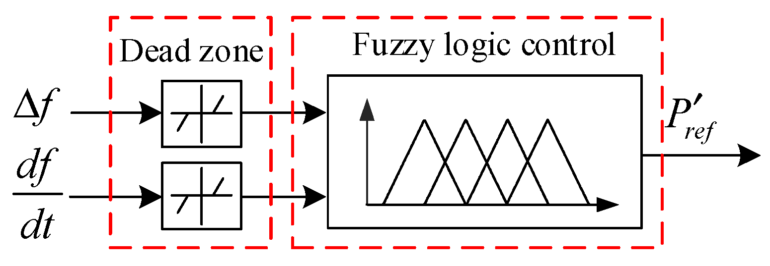
The use of additional frequency control can effectively improve the frequency stability of the VSC-MTDC system. Most of the existing control methods use droop control to determine the power reference value of the additional frequency control, which cannot adaptively adjust the power of the DC converter station according to the frequency deviation and frequency change rate, which is not conducive to the frequency stability of the system. Fuzzy logic control does not need the control object to have a fine mathematical model, so it has its unique advantages in realizing the multivariable control process [18]. Therefore, the fuzzy logic control method is used to realize the additional control of frequency in this paper. The structure of the fuzzy logic controller is shown in Figure 3.
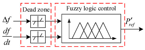
Figure 3.
Structure of fuzzy logic controller.
The input variables of the controller are the frequency deviation and frequency change rate of the faulty AC system. In order to prevent the controller from acting frequently, a dead zone link is added to the input. The corresponding ranges of the two input variables are [−0.01, 0.01] p.u. and [−0.012, 0.012] p.u.·s−1, respectively. The output variable of the controller is the active power reference value of the additional frequency control output, and the corresponding value range is [0, 0.2] p.u.
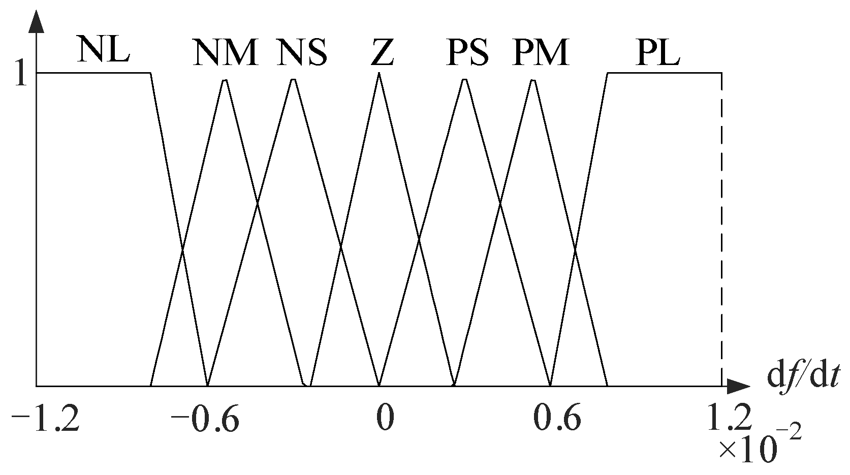
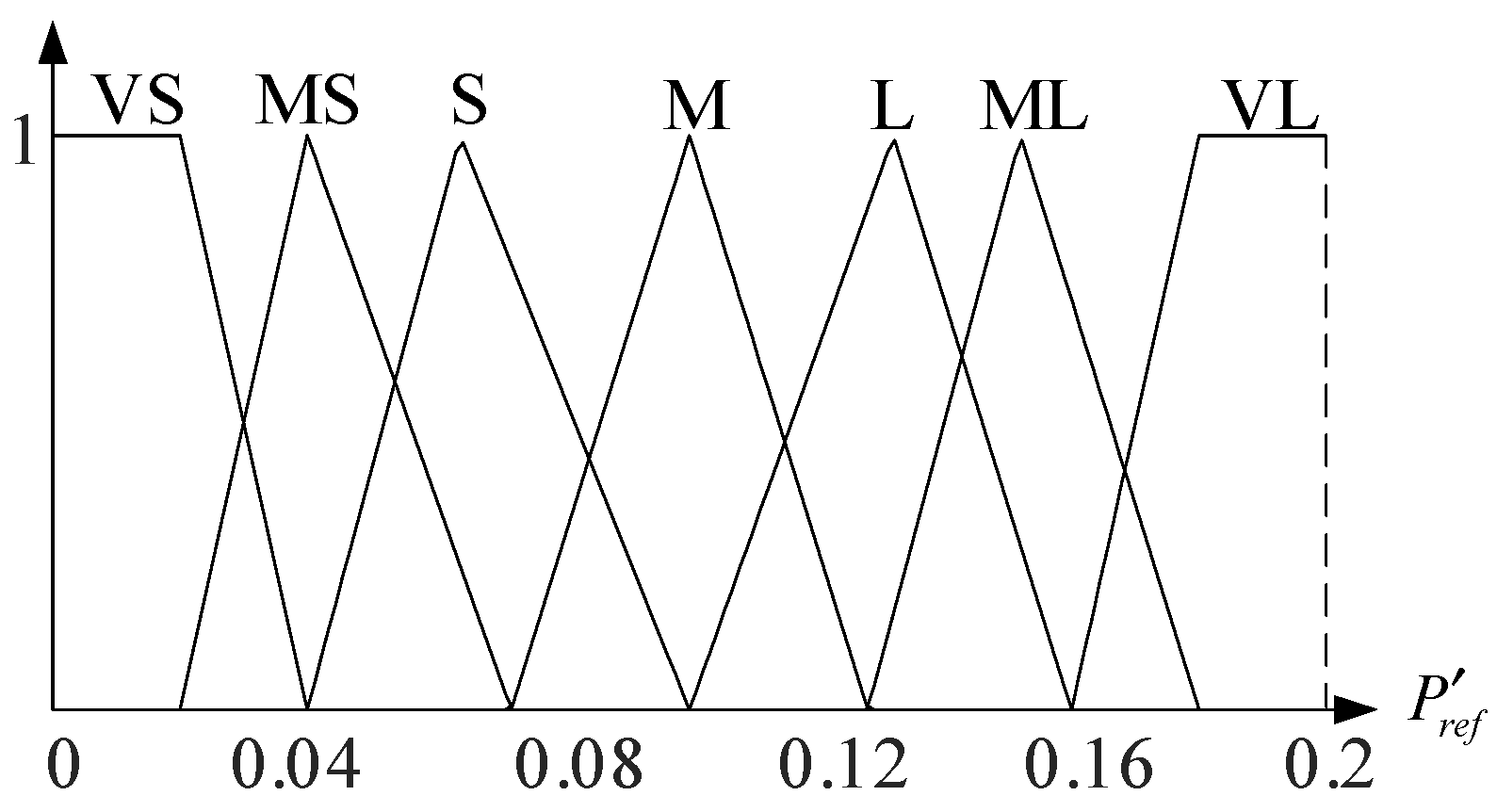
The fuzzy controller consists of seven fuzzy subsets, in which the set of fuzzy variables corresponding to the frequency deviation is as follows: negative large (NL), negative middle (NM), negative small (NS), zero (Z), positive small (PS), positive middle (PM), and positive large (PL). Moreover, frequency change rate corresponds to the same set of fuzzy variables as .The fuzzy variables corresponding to the output variable are very small (VS), middle small (MS), small (S), middle (M), large (L), middle large (ML), and very large (VL). The corresponding membership function curve is shown in Figure 4, Figure 5 and Figure 6.
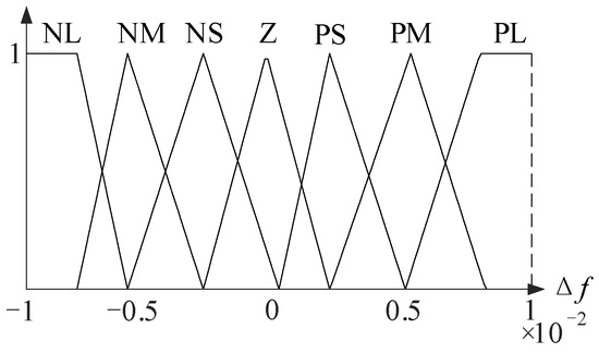
Figure 4.
Membership function corresponding to .
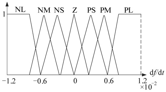
Figure 5.
Membership function corresponding to .
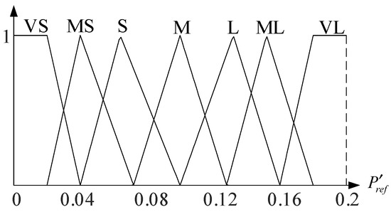
Figure 6.
Membership function corresponding to .
The fuzzy logic controller dynamically adjusts the active power reference value of the DC converter station according to the frequency deviation and frequency change rate of the faulty AC system, so that the converter station can provide an appropriate frequency response and inertial support for the faulty AC system according to actual needs. Therefore, according to the operation characteristics of the system, the fuzzy rules are designed as follows: When the absolute values of the frequency deviation and the frequency change rate of the faulty AC system are relatively small, the frequency fluctuation of the system is small, and the output variable of the fuzzy logic controller should be relatively small or the controller should not act to reduce the operation times of the DC converter station. When the absolute values of the frequency deviation and the frequency change rate are relatively large, the output variable should be as large as possible to restrain the frequency change or promote the frequency to recover quickly. According to the above rules, the table of fuzzy control rules can be obtained as shown in Table 1.

Table 1.
Fuzzy control rule table.
According to the fuzzy control rules shown in Table 1, the DC converter station can realize the adaptive adjustment of the system frequency according to the frequency deviation and frequency change rate of the faulty AC system to ensure that the frequency of the system is stable.
The dead-time link of the controller can avoid frequent movements of the controller when the frequency fluctuates slightly, and the selection of dead-time parameters will affect the response characteristics of the controller. If the dead-time parameters are set to values that are too large, the response of the controller will be too slow, which is not conducive to the stability of the frequency. If the dead-time parameter is set to a value that is too small, the controller will be too sensitive and make the controller switch frequently. According to the operation characteristics of the system, the dead-time parameter of the frequency deviation is [−0.1, 0.1] Hz, and the dead-time parameter of the frequency change rate is [−0.2, 0.2] Hz·s−1.
3.2. Frequency Stability Control Strategy of VSC-MTDC System Based on Fuzzy Logic Control
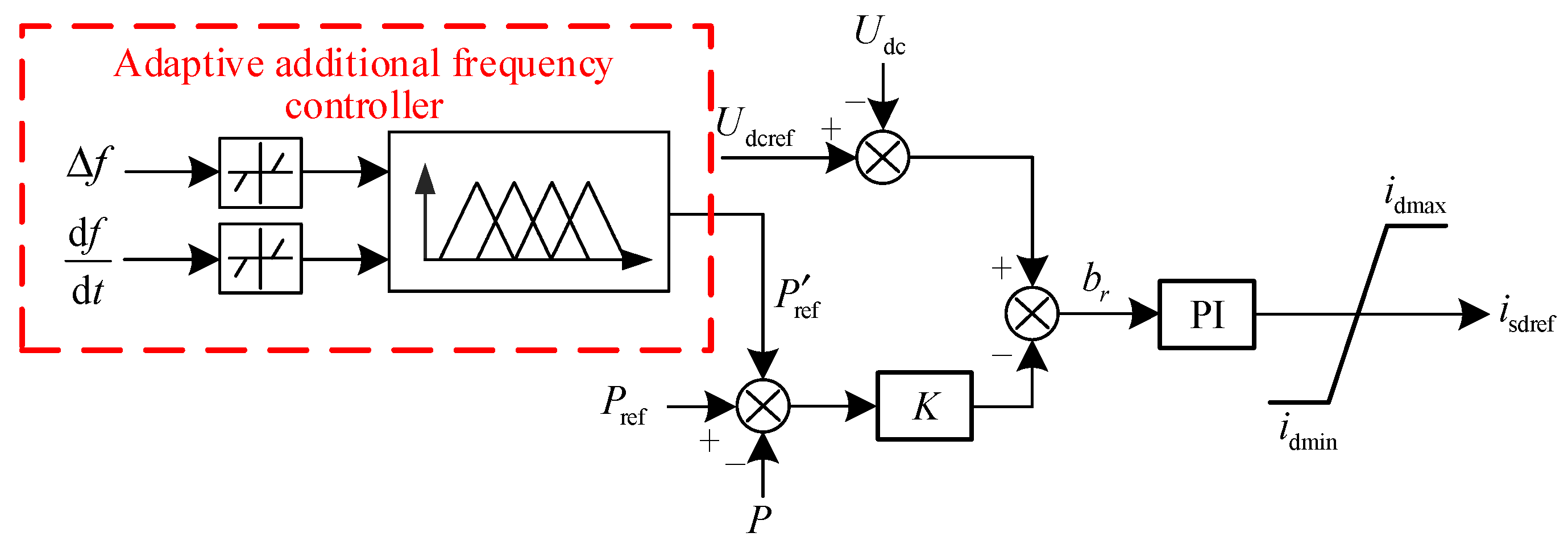
In order to make other AC systems with frequency modulation abilities participate in the frequency adjustment of the faulty AC system through the VSC-MTDC, on the basis of DC voltage slope controller, an additional frequency controller is designed based on the fuzzy logic control theory, and an additional frequency control strategy based on fuzzy logic control is proposed. The structure of the controller is shown in Figure 7.
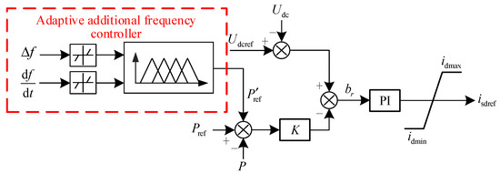
Figure 7.
Additional frequency controller based on fuzzy logic control.
The controller introduces the additional power reference value into the active power instruction value of the DC voltage slope controller, takes the frequency deviation and the frequency change rate as input variables, and obtains the output variable through the fuzzy logic controller to realize the dynamic adaptive adjustment of the frequency of the faulty AC system. When the absolute values of the frequency deviation and the frequency change rate of the system are small, the frequency of the system is relatively stable, the imbalance of active power is small, and the output variable of the fuzzy controller is also very small, which makes the converter station participate in the frequency adjustment to a small extent. When the absolute values of the frequency deviation and the frequency change rate are large, the system frequency fluctuates greatly, and the fuzzy controller adjusts the output variable according to the needs to enable the amplitude of the active power adjustment of the converter station to become larger. This is performed to ensure that power support is provided from the non-faulty AC system to the faulty AC system and ensure the stability of the whole system.
4. Simulation Verification
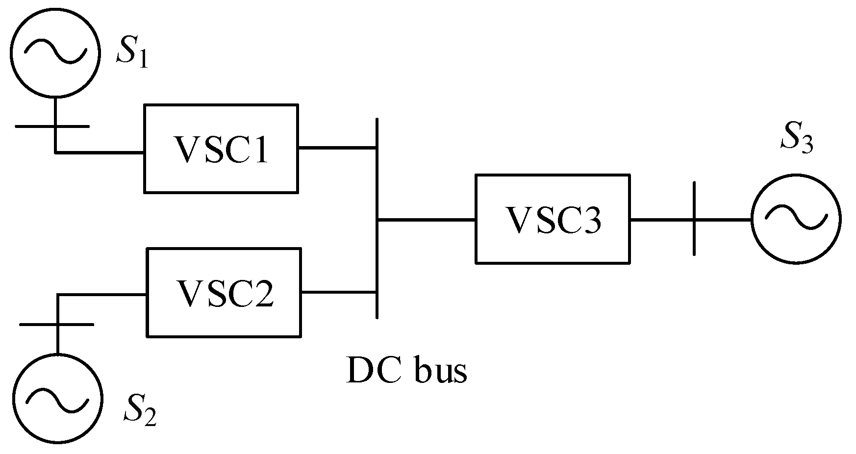
The three-terminal flexible HVDC transmission system shown in Figure 8 is built in PSCAD/EMTDC, and its simulation is carried out on three different working conditions: small power load disturbance, mechanical torque change of the generator set, and DC system fault. Compared with the constant DC voltage slope control mentioned above, the effectiveness of the strategy proposed in this paper is verified.

Figure 8.
Three-terminal flexible HVDC system.
S1~S3 is an AC system, its installed capacity is 384, 288, and 288 MW. VSC1 and VSC2 are rectifier stations, and VSC3 is an inverter station with a rated capacity of 60, 60, and 120 MW, and rated positive and negative DC voltage of 200 kV; moreover, ±7.5% of Udcref is taken as the limit value of DC voltage fluctuation. The active power of the converter station is in the positive direction of the injection AC side, and the control strategy proposed in this paper is adopted in the three converter stations. The active power instruction values in the initial state are 40, 35, and 75 MW.
4.1. Small Power Load Disturbance
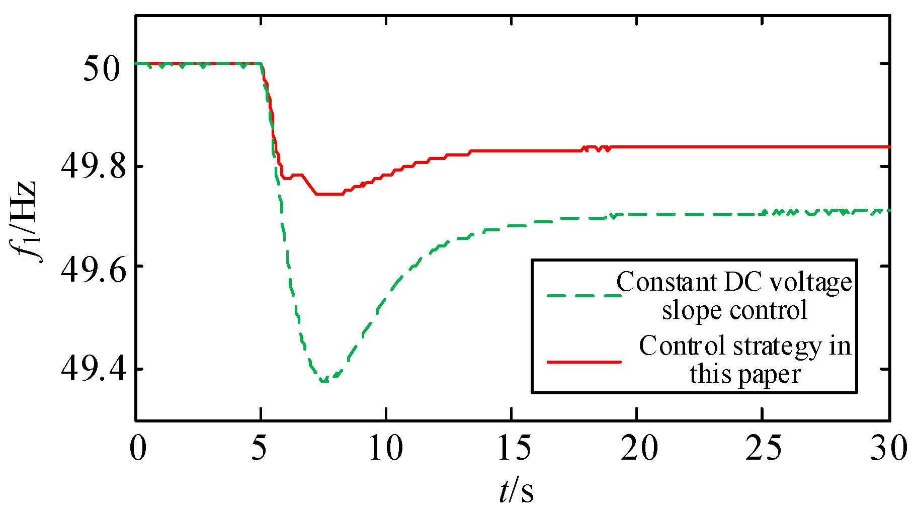
After the three-terminal flexible HVDC transmission system is stable, and the following working conditions are set for the simulation: the load of AC system S1 is increased from 300 MW to 330 MW at 5 s, and one of the AC systems is disturbed by low power load. The simulation results of the frequency curves of the AC systems S1~S3 are shown in Figure 9, Figure 10 and Figure 11.
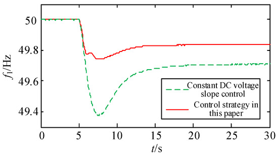
Figure 9.
Frequency of S1 AC system.

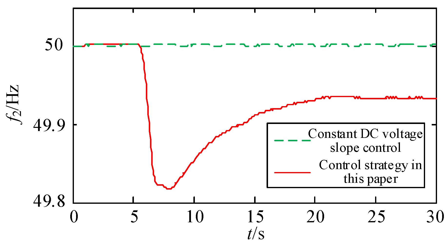
Figure 10.
Frequency of S2 AC system.
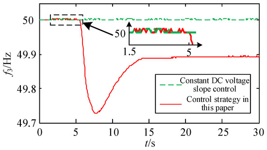
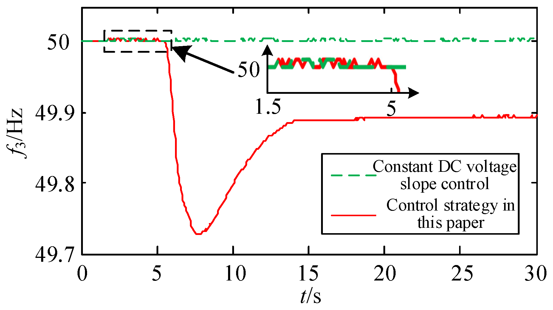
Figure 11.
Frequency of S3 AC system.
It can be seen from the figure that when the S1 system has load disturbance, the frequency of the system shifts accordingly. Under the traditional constant DC voltage slope control strategy, as the DC system cannot respond to the frequency of the disturbed AC system, the lowest frequency of the S1 system exceeds 49.4 Hz, and the quasi-steady-state frequency reaches 49.72 Hz. The offset is large, which may cause the load shedding action of the system and affect the reliable operation of the system. Although the system frequencies of AC systems S2 and S3 are not affected, they also sacrifice their frequency support ability for the S1 AC system, which is not conducive to the stable operation of the whole system. In contrast, when the converter station adopts the control strategy proposed in this paper, the lowest frequency of the S1 system is 49.75 Hz, and the quasi-steady-state frequency is 49.84 Hz, and the frequency characteristic is obviously improved. The converter station makes full use of the frequency modulation capability of other AC systems to support the frequency of the disturbed AC system, which significantly improves the frequency stability of the system.
The active power corresponding to the converter station VSC1~VSC3 is shown in Figure 12, Figure 13 and Figure 14.
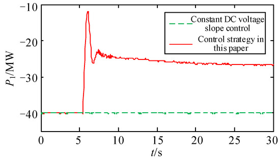
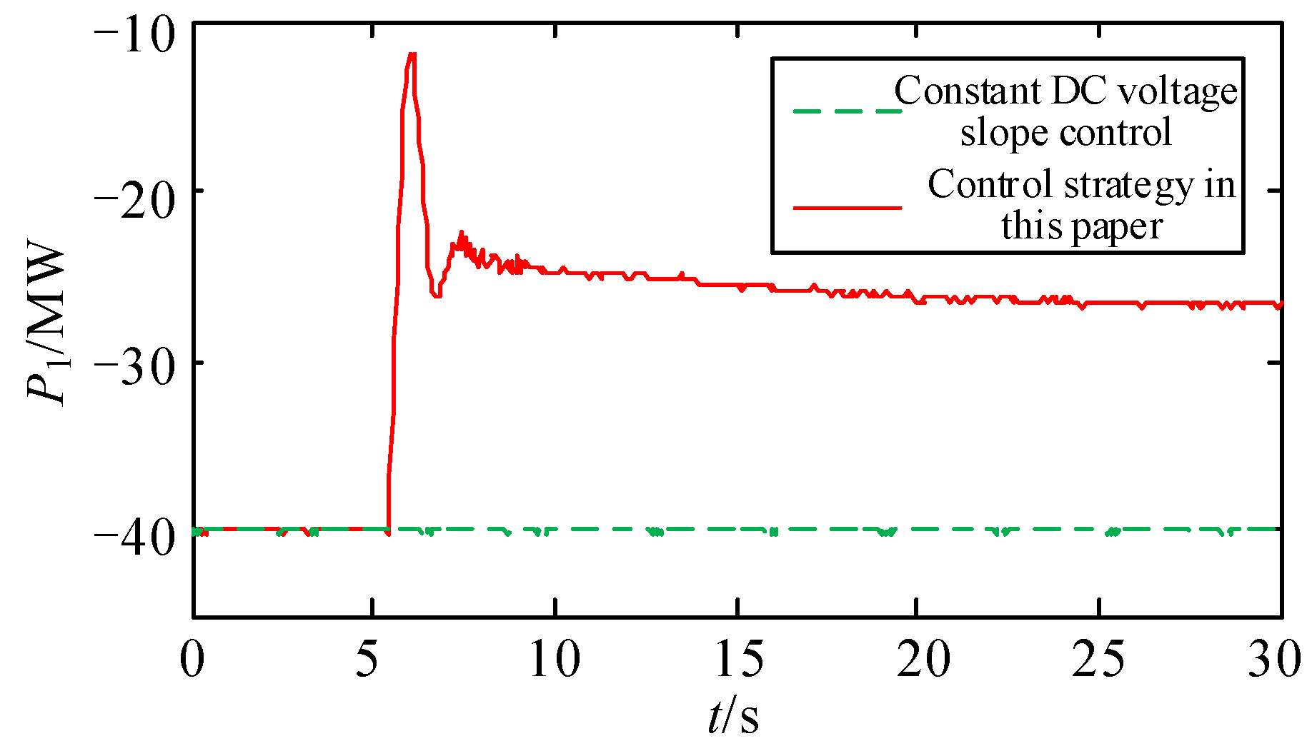
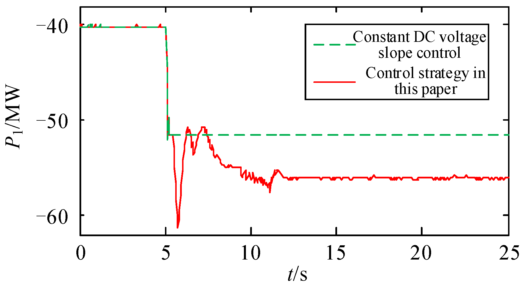
Figure 12.
Active power of converter station VSC1.

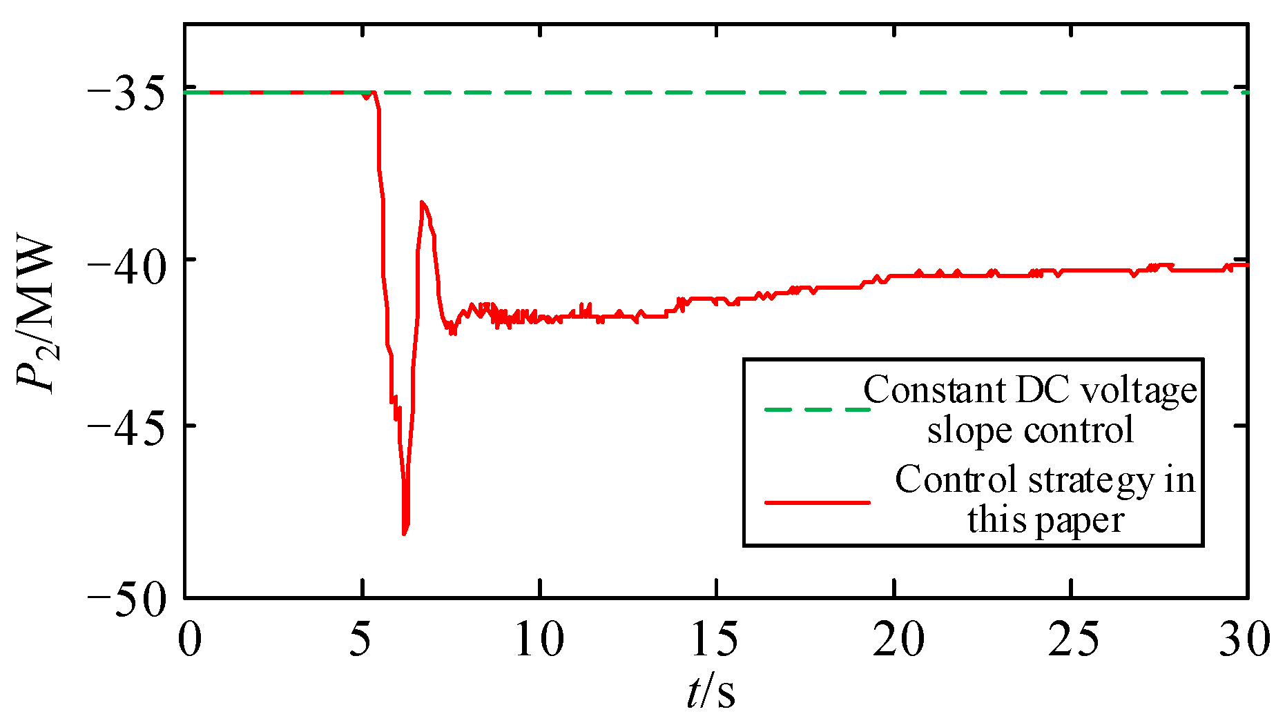
Figure 13.
Active power of converter station VSC2.
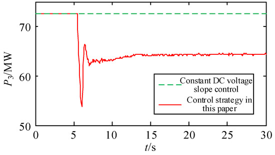
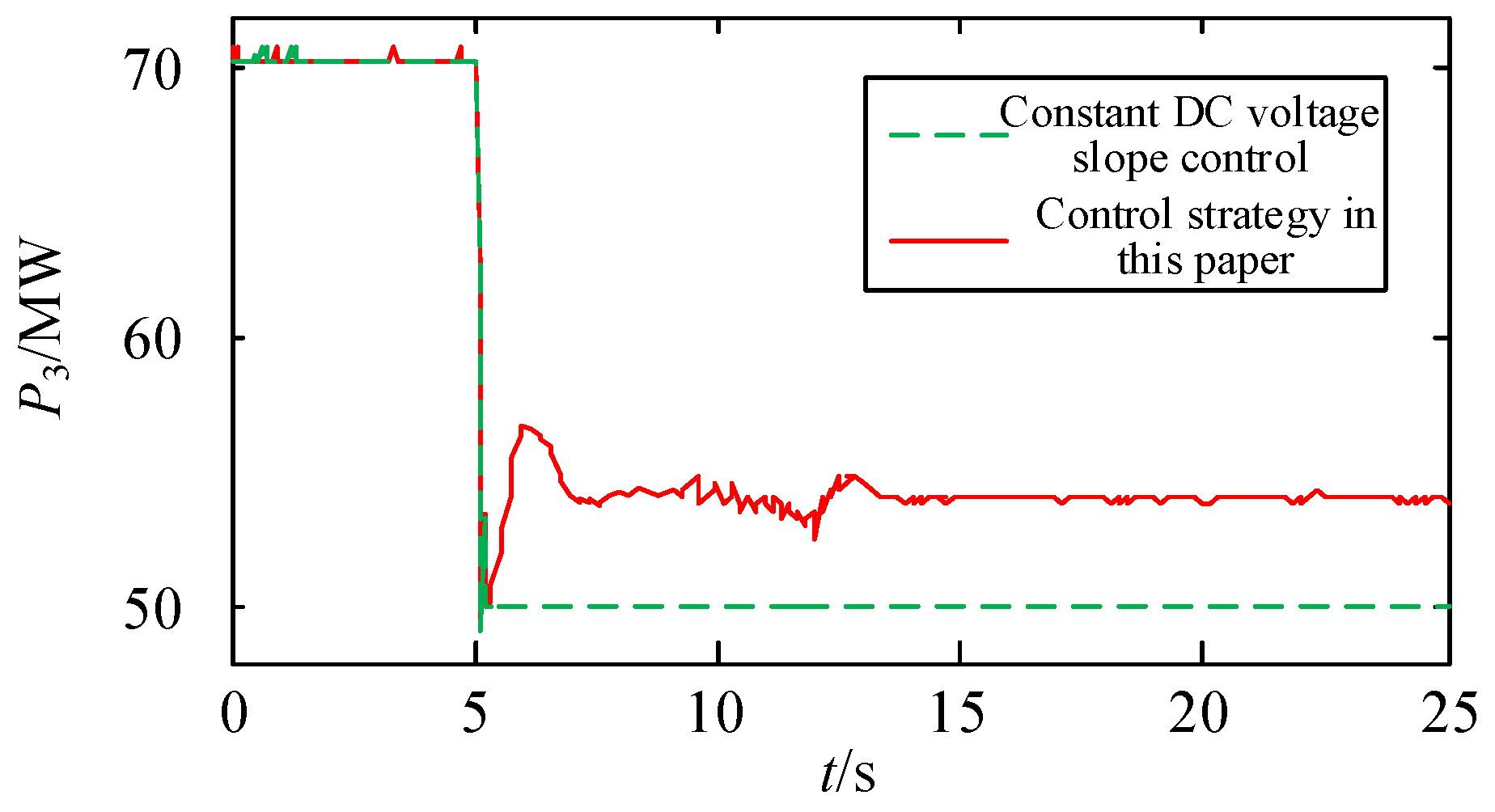
Figure 14.
Active power of converter station VSC3.
As can be seen from Figure 12, Figure 13 and Figure 14, under the traditional constant DC voltage slope control strategy, the active power of the converter station remains constant and will not be adjusted according to the frequency change of the AC system. Under the strategy proposed in this paper, the active power of converter station VSC1 increases by 13 MW, which is equivalent to the load of the S1 system decreasing by 13 MW. Thus, the lowest frequency of the S1 system increases by 0.39 Hz, the quasi-steady-state frequency increases by 0.12 Hz, the active power of converter stations VSC2 and VSC3 decreases by 5 MW and 8 MW, respectively, and the system frequency deviations of AC systems S2 and S3 remain within the range of stable operation. Therefore, this strategy effectively improves the frequency stability of the S1 system on the premise of ensuring the frequency stability of the S2 and S3 systems.
4.2. Variation of Mechanical Torque of Generator Set
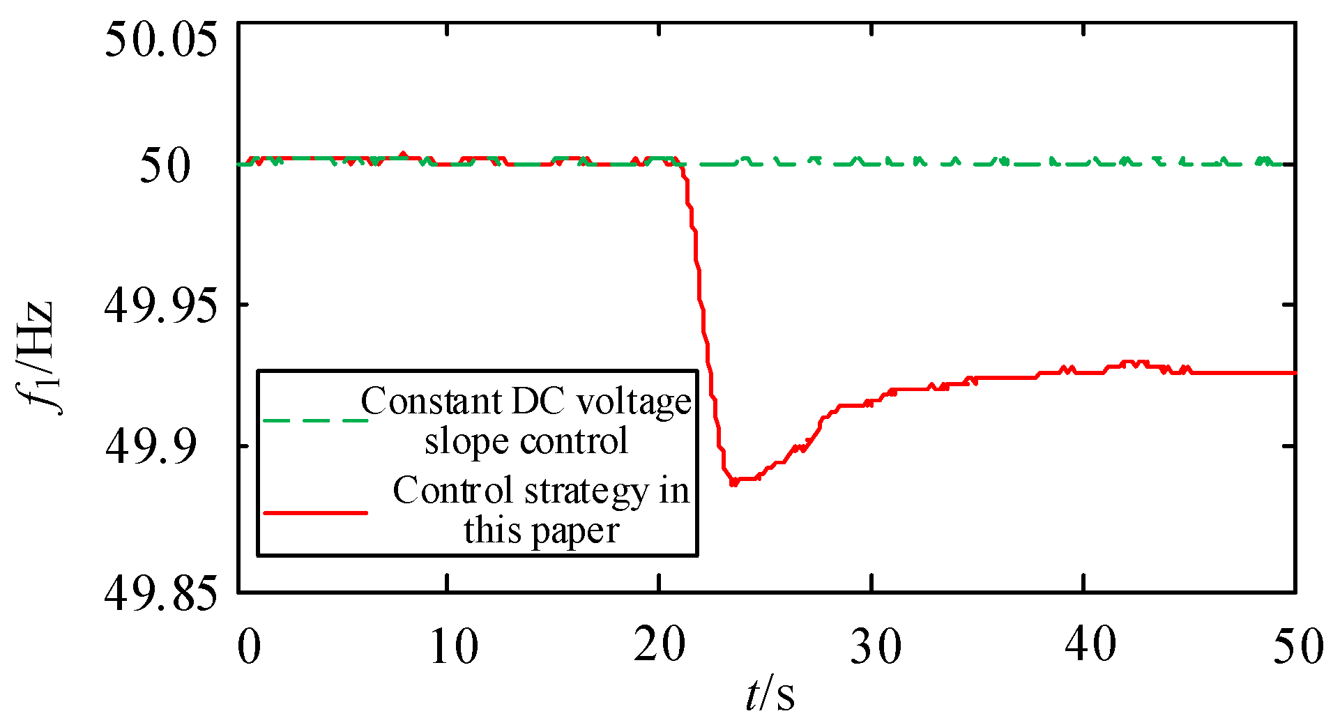
Considering the operation of the generator set, the set operating conditions are as follows: the mechanical torque input of the S3 system’s generator set is reduced by 0.15% at 5 s and by 0.6% again at 20 s, simulating the situation of continuous disturbance on the generation side. The simulation results of the frequency curves of the AC systems S1~S3 are shown in Figure 15, Figure 16 and Figure 17.
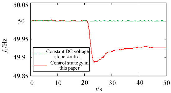
Figure 15.
Frequency of S1 AC system.
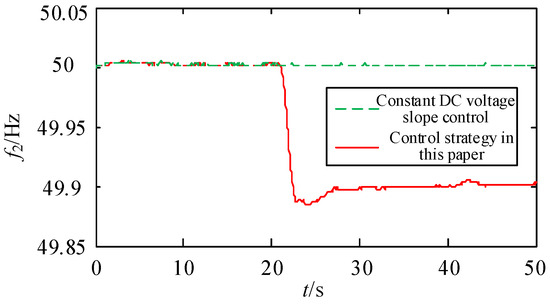
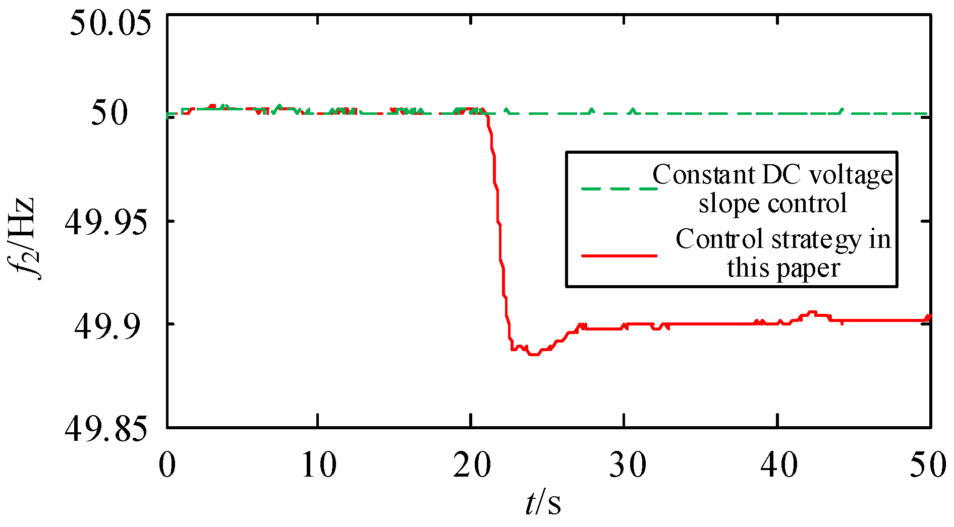
Figure 16.
Frequency of S2 AC system.

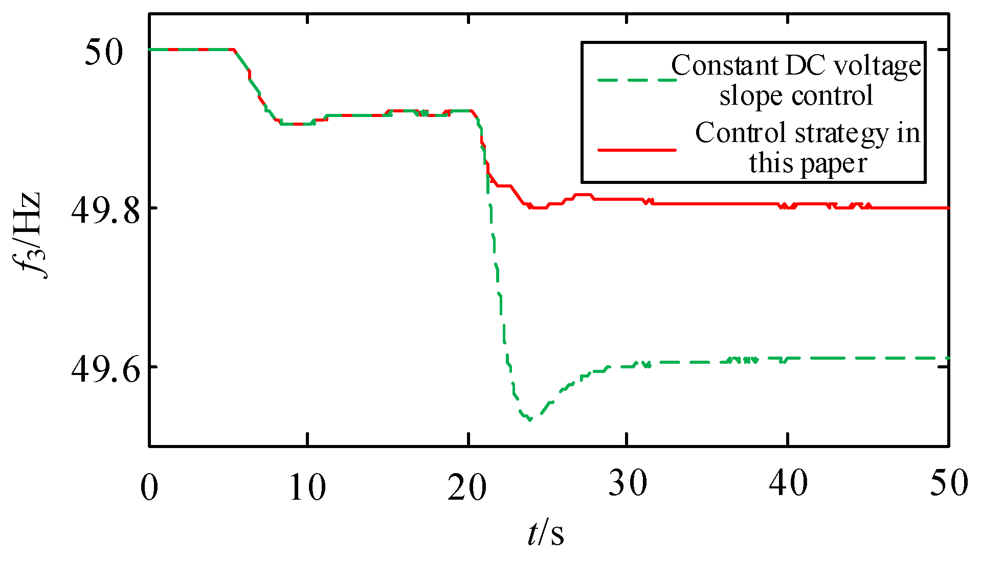
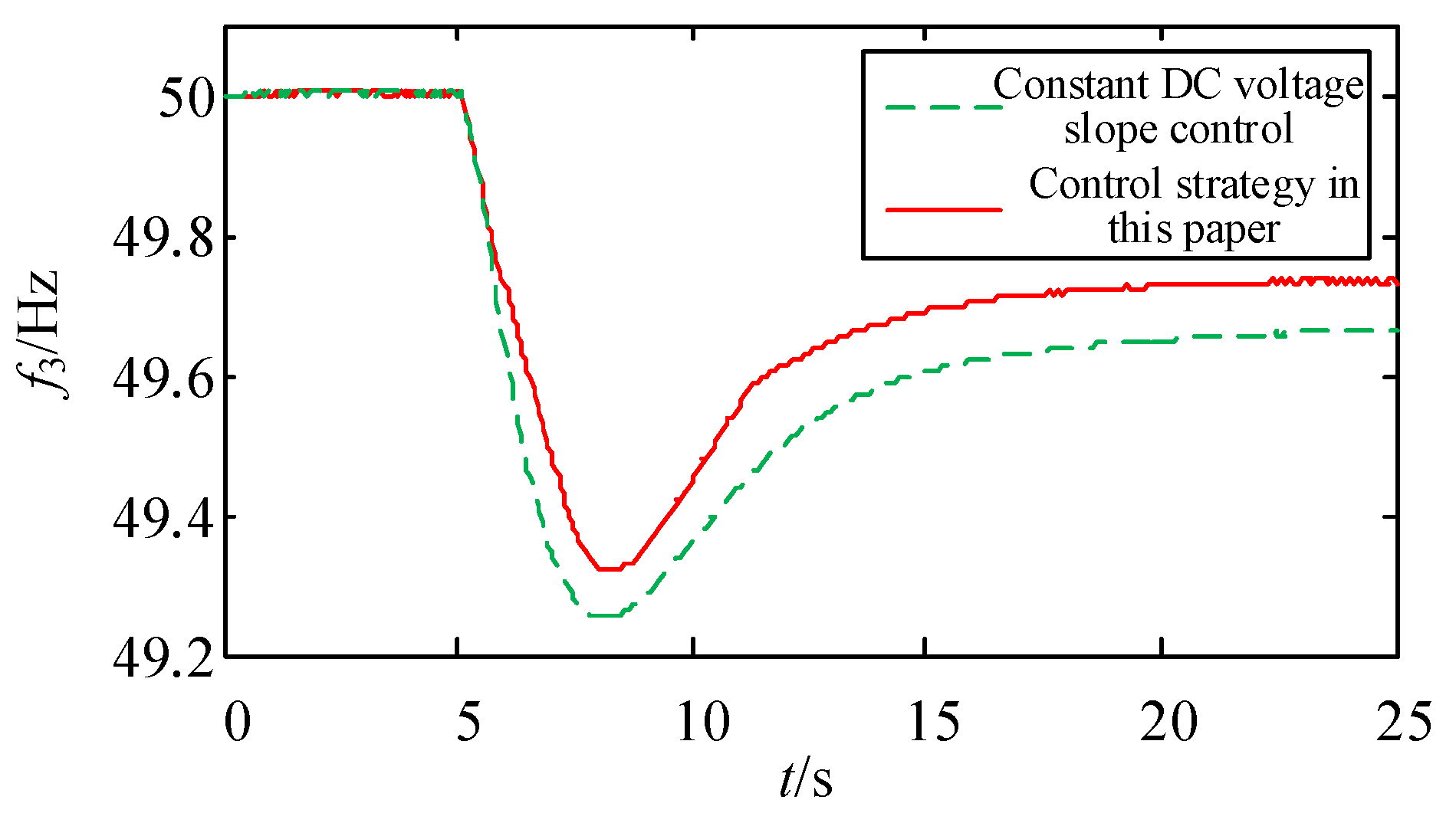
Figure 17.
Frequency of S3 AC system.
As can be seen from Figure 15, Figure 16 and Figure 17, when the time t increases from 0 s to 20 s, the frequency deviation of AC system S3 is in the dead zone of the controller set in this paper because the disturbance is small and the frequency offset is small, so the additional frequency controller will not work. At the same time, the frequencies of the S1 and S2 systems have not changed. Due to the fault of the generator being more serious under the traditional constant DC voltage slope control strategy, when the time t increases from 20 s to 50 s, the lowest frequency of the S3 system reaches 49.54 Hz, the quasi-steady-state frequency is 49.61 Hz, the frequency offset is serious, and the system faces the risk of load reduction or instability. Under the control strategy proposed in this paper, because the frequency deviation of the S3 system exceeds the dead-time limit of the controller, the additional frequency controller based on fuzzy logic control starts to act. According to the frequency deviation and frequency change rate of the system, the converter station participates in the dynamic adaptive adjustment of the S3 system’s frequency. It can be seen from Figure 17 that the lowest frequency of S3 system is 49.8 Hz after adopting the control strategy proposed in this paper, and compared with the traditional control strategy, the 0.26 Hz improved, the quasi-steady frequency increased to 0.19 Hz, and the frequency characteristic significantly improved.
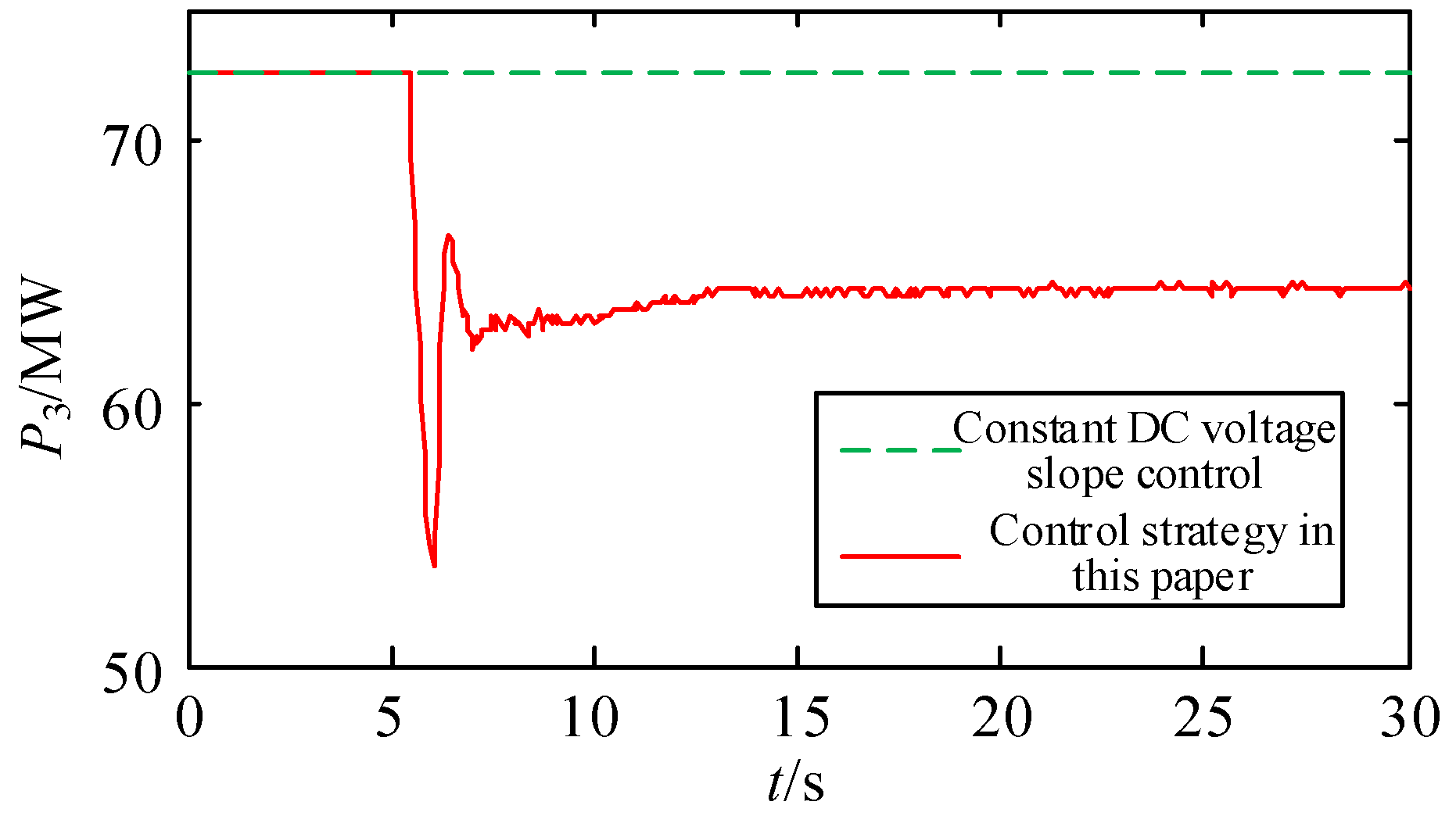
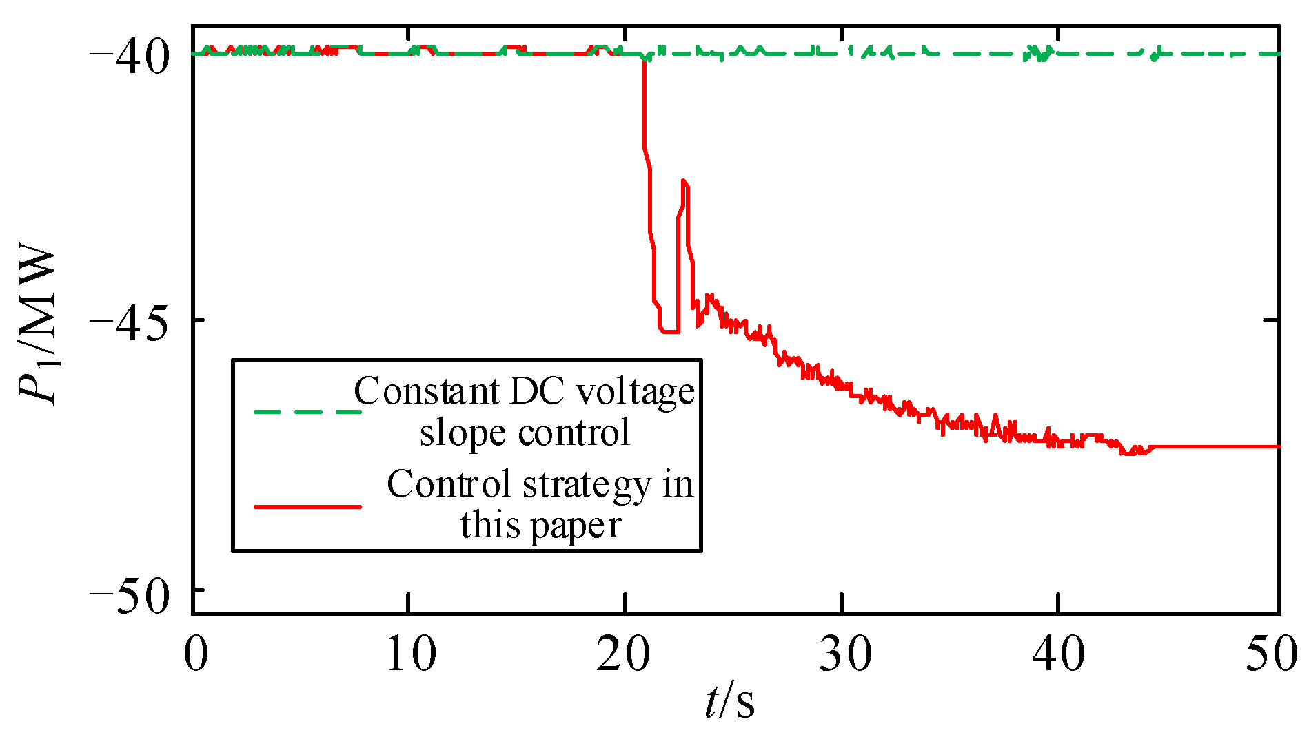
The active power corresponding to the converter station VSC1~VSC3 is shown in Figure 18, Figure 19 and Figure 20.

Figure 18.
Active power of converter station VSC1.

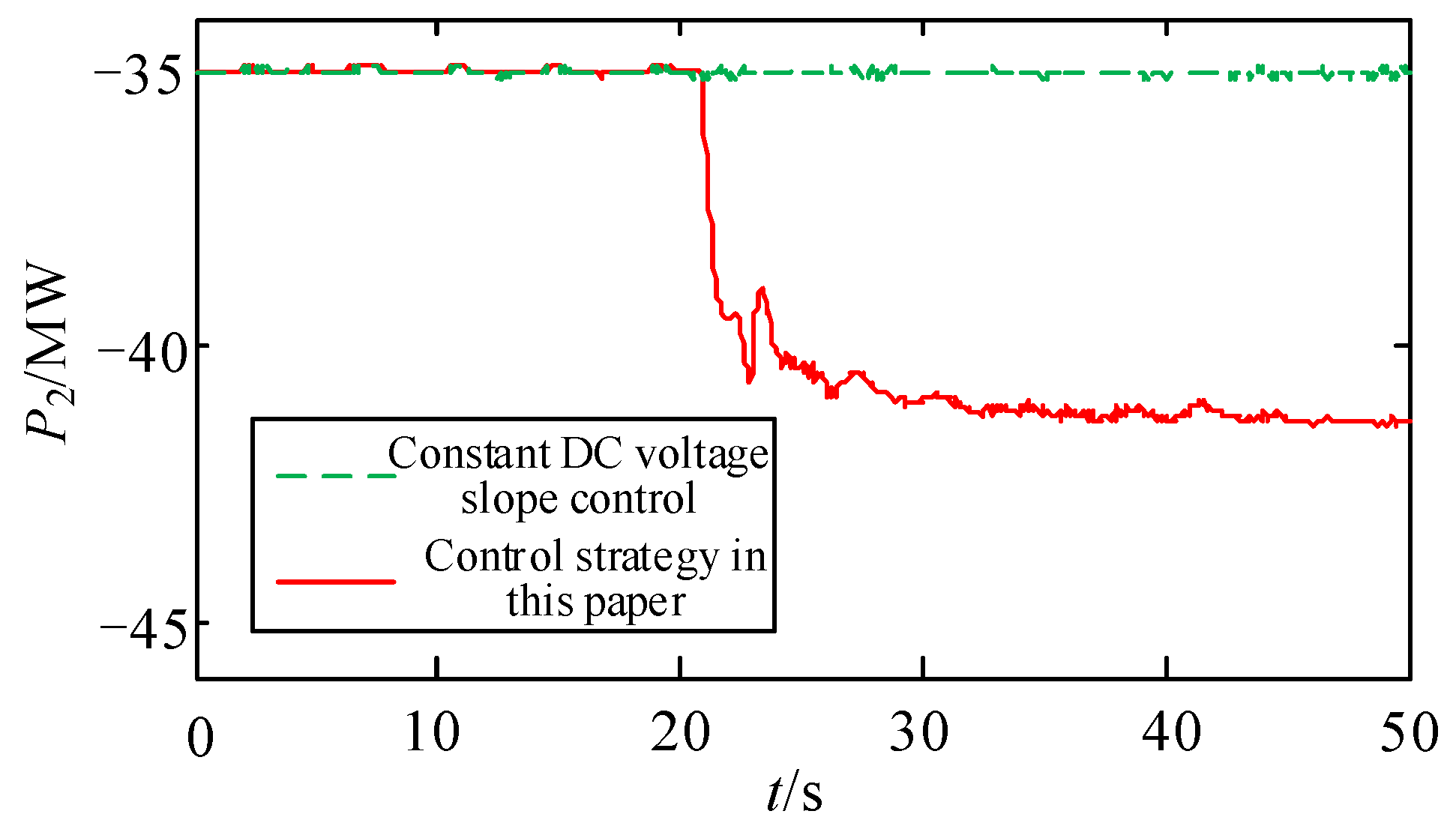
Figure 19.
Active power of converter station VSC2.
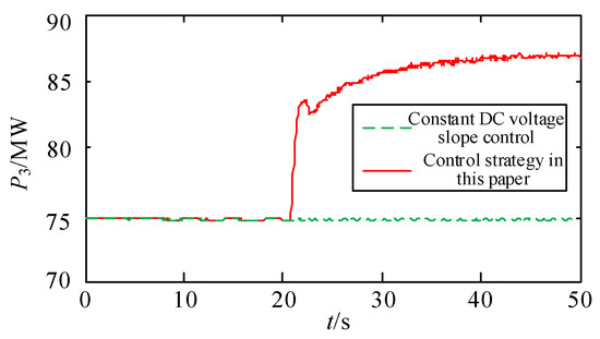
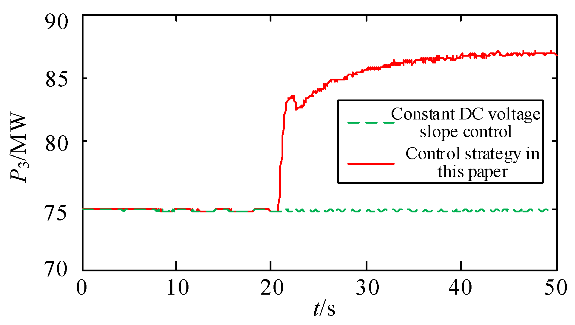
Figure 20.
Active power of converter station VSC3.
As can be seen from Figure 18, Figure 19 and Figure 20, under the traditional constant DC voltage slope control strategy, the active power transmitted by the converter station does not change, and the frequency support between interconnected AC systems cannot be realized.
Under the control strategy proposed in this paper, when the time increases from 20 s to 50 s, the active power transmitted by the converter station VSC1 increases by 13 MW, which is equivalent to the increase in the power generation of system S3. The active power transmitted by VSC1 and VSC2 in the converter station decreases by 7 MW and 6 MW, respectively, which is equivalent to increasing the load for systems S1 and S2. The control strategy proposed in this paper realizes the frequency support between interconnected AC systems by adjusting the DC transmission power. As can be seen from Figure 15 and Figure 16, although the frequencies of systems S1 and S2 are affected, the frequency offset is always within an acceptable range and can be operated in a stable condition for a long time.
4.3. DC System Fault
Considering the DC system’s failure, the set operating conditions are as follows: VSC2 withdrew from the operation due to a fault at 5 s. The simulation’s results are shown in Figure 21, Figure 22, Figure 23 and Figure 24.
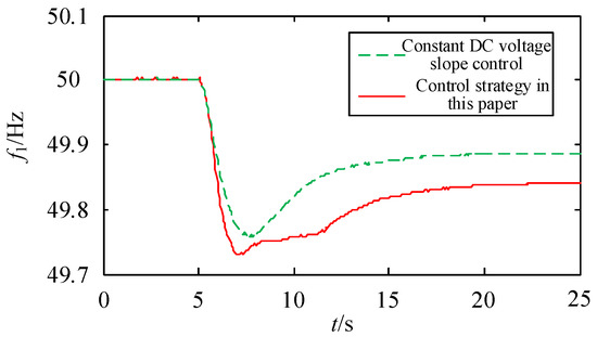
Figure 21.
Frequency of S1 AC system.
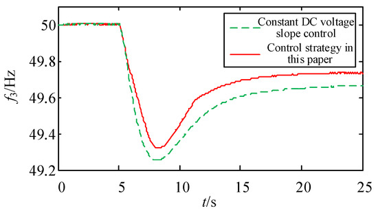
Figure 22.
Frequency of S3 AC system.
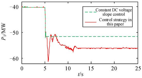
Figure 23.
Active power of converter station VSC1.
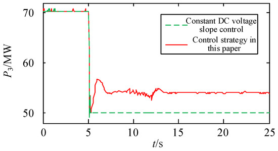
Figure 24.
Active power of converter station VSC3.
As can be seen from Figure 21, Figure 22, Figure 23 and Figure 24, after VSC2 is out of operation, the unbalanced power of 35 MW appears in the DC network, which is shared by VSC1 and VSC3. Under the conventional control strategy, the frequency modulation capability of the AC system connected to the converter station is not considered. The unbalanced power shared by VSC1 and VSC3 according to the DC voltage characteristic curve is 12 MW and 23 MW, respectively, resulting in quasi-steady-state frequency deviations of 0.11 Hz and 0.33 Hz; for and , respectively, the quasi-steady-state frequency deviation of is too large, which will lead to the operation of the low-cycle load-shedding device. This is not conducive to the reliable operation of the system. After adopting the control strategy in this paper, the unbalanced power shared by VSC1 is 16 MW. Due to the decrease of the absolute value of the shared power, the frequency deviation of F1’s quasi-steady state is 0.16 Hz. Although the absolute value of frequency deviation increases, it is still in the long-term stable operation range. At the same time, the active power regulation of VSC3 is 17 MW, which improves the quasi-steady-state frequency of the S3 system, and the deviation is reduced to 0.25 Hz. Compared with the traditional control strategy, the absolute value of deviation is reduced by 0.08 Hz, which effectively improves the frequency stability of the system.
5. Conclusions
In this paper, for the VSC-MTDC-interconnected system, a frequency stability control strategy based on fuzzy logic control is proposed, which effectively improves the frequency stability of the system.
The main conclusions are as follows:
(1) The control strategy proposed in this paper does not need communication, and the converter station responds to the frequency of the AC side system through additional frequency control. Moreover, multiple converter stations share unbalanced power in the DC network. When the frequency of one AC system changes greatly, the AC systems support each other through VSC-MTDC, and even pull the frequency unstable system into stability.
(2) In this paper, a dead-time link is designed in the additional frequency controller, which can not only ensure the effect of frequency control but also avoid the frequent action of the controller because of the small fluctuation of frequency.
(3) The fuzzy logic control method proposed in this paper takes the frequency deviation and frequency change rate as input variables, which can enable the converter station to dynamically adjust the transmitted active power and realize the adaptive frequency regulation of the faulty AC system.
The main contributions of this paper are as follows: Firstly, the frequency change rate and frequency deviation are used as the inputs of the fuzzy logic controller, and the frequency change rate can reflect the inertia level of the power system. Taking the frequency change rate as the input can make the DC system provide inertial support for the system. Secondly, the fuzzy logic controller is applied to the multi-terminal flexible HVDC system, and the frequency control is carried out by using the regulation ability of the DC converter station, which can make full use of the frequency modulation ability of the DC system and improve the frequency stability of the AC system. The frequency control method proposed in this paper for the multi-terminal flexible HVDC system can provide a certain reference value for the engineering applications of multi-terminal flexible HVDC transmissions.
Author Contributions
Conceptualization, C.X., M.L. and Y.W.; data curation, Y.W., J.L. and S.G.; formal analysis, M.L.; funding acquisition, Z.Z.; investigation, J.P.; methodology, C.X., J.P. and C.S.; project administration, Y.W.; software, Z.Z., J.L. and S.G.; supervision, Y.W.; validation, C.X., C.S. and Z.Z.; writing—original draft preparation, C.X., M.L. and J.P.; writing—review and editing, C.X., M.L. and Y.W. All authors have read and agreed to the published version of the manuscript.
Funding
This work was partially supported by the National Natural Science Foundation of China (62101362, 52307127), the Project of State Key Laboratory of Power System Operation and Control (SKLD23KZ07), and the Fundamental Research Funds for the Central Universities (YJ202141, YJ202316).
Data Availability Statement
The data set can be obtained by contacting the corresponding author. The data are not publicly available due to the experimental data are confidential.
Conflicts of Interest
Author Chao Xing, Mingqun Liu, Junzhen Peng were employed by the company Electric Power Research Institute of Yunnan Power Grid Co., Ltd. The remaining authors declare that the research was conducted in the absence of any commercial or financial relationships that could be construed as a potential conflict of interest.
References
- Akshaya, M.; Dash, P.K. Input-output linearization and robust sliding-mode controller for the VSC-HVDC transmission link. IEEE Trans. Power Deliv. 2010, 25, 1952–1961. [Google Scholar]
- Deng, Y.Q.; Wang, Z.; Han, J.F. Unbalanced power optimal distribution control strategy for multi-terminal flexible straight network suitable for offshore wind power access. Proc. CSEE 2020, 40, 2406–2416. [Google Scholar]
- Wang, Y.H.; Zhu, J.; Zeng, Q.; Tai, K.Q. Multi-objective bi-level optimization design method of DC frequency limiting controller parameters. Electr. Power Autom. Equip. 2022, 42, 189–196. [Google Scholar]
- Ye, Y.D.; Ying, Q.; Xie, L. A comprehensive power flow approach for multi-terminal VSC-HVDC system considering cross-regional primary frequency responses. J. Mod. Power Syst. Clean Energy 2020, 8, 238–248. [Google Scholar] [CrossRef]
- Wang, Y.H.; Shang, C.B.; Liao, J.Q. Adaptive frequency modulation control strategy for asynchronous connected HVDC transmission system adapted to wind power access. Electr. Power Autom. Equip. 2023, 43, 218–225. [Google Scholar]
- Zhang, Q.; Mccalley, J.; Ajjarapu, V. Primary frequency support through north American continental HVDC interconnections with VSC-MTDC systems. IEEE Trans. Power Syst. 2021, 36, 806–817. [Google Scholar] [CrossRef]
- Xu, D.G.; Liu, Y.C.; Wu, J. Review on control strategies of multi-terminal direct current transmission system. Trans. China Electrotech. Soc. 2015, 30, 1–12. [Google Scholar]
- Zhu, L.H.; Yuan, Z.C.; Sheng, C. Review of frequency support control methods for asynchronous inter-connection system based on VSC-HVDC. Electr. Power Autom. Equip. 2019, 39, 84–92. [Google Scholar]
- Nilanjan, R.C.; Rajat, M.; Balarko, C. System frequency support through Multi-Terminal DC(MTDC)grids. IEEE Trans. Power Syst. 2013, 28, 347–356. [Google Scholar]
- Zhu, R.K.; Li, X.Y.; Ying, D.L. A frequency stability control strategy for interconnected VSC-MTDC transmission system. Power Syst. Technol. 2014, 38, 2729–2734. [Google Scholar]
- Dai, J.; Phulpin, Y.; Sarlette, A. Coordinated primary frequency control among non-synchronous systems connected by a multi-terminal high-voltage direct current grid. IET Gener. Transm. Distrib. 2012, 6, 99–108. [Google Scholar] [CrossRef]
- Zhu, J.; Campbell, D.B.; Grain, P.A. Inertia emulation control strategy for VSC-HVDC transmission systems. IEEE Trans. Power Syst. 2013, 28, 1277–1287. [Google Scholar] [CrossRef]
- Wang, R.; Chen, L.; Zheng, T. VSG-based adaptive droop control for frequency and active power regulation in the MTDC system. CSEE J. Power Energy Syst. 2017, 3, 260–268. [Google Scholar] [CrossRef]
- Wang, W.Y.; Li, Y.; Cao, Y.J. Adaptive droop control strategy participating in power grid frequency regulation for VSC-MTDC transmission systems. Autom. Electr. Power Syst. 2017, 41, 142–149. [Google Scholar]
- Zhai, D.L.; Han, M.X.; Ma, J.P. Adaptive droop control of VSC-MTDC connected to low inertia system. Electr. Power Autom. Equip. 2019, 39, 128–134. [Google Scholar]
- Yan, S.; Gu, Z.; Park, J.H.; Xie, X.P. A delay-kernel-dependent approach to saturated control of linear systems with mixed delays. Automatica 2023, 152, 110984. [Google Scholar] [CrossRef]
- Yan, S.; Gu, Z. Sampled Memory-Event-Triggered Fuzzy Load Frequency Control for Wind Power Systems Subject to Outliers and Transmission Delays. IEEE Trans. Cybern. 2023, 53, 4043–4053. [Google Scholar] [CrossRef] [PubMed]
- Zhang, S.; Mishra, Y.; Shahidehpour, M. Fuzzy-logic based frequency controller for wind farms augmented with energy storage systems. IEEE Trans. Power Syst. 2016, 31, 1595–1603. [Google Scholar] [CrossRef]


Disclaimer/Publisher’s Note: The statements, opinions and data contained in all publications are solely those of the individual author(s) and contributor(s) and not of MDPI and/or the editor(s). MDPI and/or the editor(s) disclaim responsibility for any injury to people or property resulting from any ideas, methods, instructions or products referred to in the content. |
© 2024 by the authors. Licensee MDPI, Basel, Switzerland. This article is an open access article distributed under the terms and conditions of the Creative Commons Attribution (CC BY) license (https://creativecommons.org/licenses/by/4.0/).