Abstract
The insufficiency of energy supply and availability remains a significant global energy challenge. This work proposes a novel approach to addressing global energy challenges by testing the supercritical property and conversion of low-temperature thermal heat into useful energy. It introduces a combined-cascade steam-to-steam trigeneration cycle integrated with vapour absorption refrigeration (VAR) and district heating systems. Energetic and exergetic techniques were applied to assess irreversibility and exergetic destruction. At a gas turbine power of 26.1 MW, energy and exergy efficiencies of 76.68% and 37.71% were achieved, respectively, while producing 17.98 MW of electricity from the steam-to-steam driven cascaded topping and bottoming plants. The cascaded plant attained an energetic efficiency of 38.45% and an exergy efficiency of 56.19%. The overall cycle efficiencies were 85.05% (energy) and 77.99% (exergy). More than 50% of the plant’s lost energy came from the combustion chamber of the gas turbine. The trigeneration system incorporated a binary NH3–H2O VAR system, emphasizing its significance in low-temperature energy systems. The VAR system achieved a cycle exergetic efficiency of 92.25% at a cooling capacity of 2.07 MW, utilizing recovered waste heat at 88 °C for district hot water. The recovered heat minimizes overall exergy destruction, enhancing thermal plant performance.
1. Introduction
Electricity demand, consumption, and supply exhibit global disparities [1]. Some regions have surplus power, while others face deficits [2]. Renewable energy potential varies by location, including wave or tidal power, hydroelectric power (HEP), wind power, geothermal power, and solar power. Projections estimate a 56% increase in global energy consumption by 2040, with developing countries benefiting due to factors like population growth, technological advancements, emerging economies, and higher living standards [3]. Research addresses these challenges, with roadmaps and projections suggesting the value of combined-cycle power plant technology as a low-carbon power supply backup, as outlined in the European Union Energy Road Map 2050 [4]. Combined-cycle power plants (CCPPs), known for their efficiency, low complexity, and low emissions, utilize gas and steam turbine cycles [5]. This paper focuses on testing the supercritical properties of water in a steam-to-steam trigeneration system using exhaust heat from a gas turbine converted by a waste heat recovery (WHR) device to generate electricity. This system also powers an ammonia refrigerant generator for a vapour absorption refrigeration (VAR) system [6]. The steam-to-steam technology offered in this work is a simple and feasible alternative to fossil-fuel-based energy production and utilization systems, particularly for the use of low-grade thermal heat sources like condensation heating to reduce fuel costs. This study applies the laws of thermodynamics to assess the behaviour and efficiency of a trigeneration system. Emphasizing an exergetic methodology, the present study diagnoses sources of irreversibility and targets performance enhancements in integrated plant components. The goal is to improve the overall conduct of complex energy systems.
2. Literature Review
Energy systems interact with external non-thermal systems, presenting challenges in energy, economics, and the environment across boundaries. The conventional assessment of energy system performance using the first law of thermodynamics is criticized for its limitations in determining irreversibility and losses [7,8]. Exergy, based on the second law of thermodynamics, emerges as a crucial tool to analyse the magnitude, origin, and location of energy losses and destroyed system exergy [8]. Exergy-based analysis is documented as a methodology for evaluating energy performance in different locations [9,10,11]. The results guide improvements in plant efficiency, design, economic benefits, and environmental impact assessments [12,13,14,15]. Technical analyses include CO2-capturing technology in gas turbines [10]. Ibrahim et al. [16] conducted a parametric analysis to optimize the performance of CCPP and improved the efficiency of future renewable energy sources. Bracco and Silvia [11] optimized stream pressure values by adjusting to different target functions.
The thermodynamic property evaluation of a combined cycle involves the examination of various steam plant bottoming cycles [17,18,19]. Xiang and Chen [12] scrutinized a three-pressured HRSG integrated with a general electric (GE) gas turbine, emphasizing efficiency improvement and exergy loss reduction through HRSG operating parameter optimization. Cogeneration plants, utilizing both gas and steam turbine cycles, have been introduced, exploring cumulative efficiency improvement strategies [13,14,20]. Raising the gas turbine inlet temperature to 1427 °C in a combined cycle has been identified as a potential avenue to achieve an overall efficiency of 60% [13]. Bassily [14] introduced a modelling methodology for reducing irreversibility in the HRSG of a combined-cycle, dual-pressure reheat through optimization. Innovative approaches like the application of supercharge devices to reduce HRSG sizes and save energy in a compressor-driven gas turbine have been discussed [15]. Kwon et al. [21] evaluated the integration of solar power into a CCPP with a hybrid model of HRSG and a supercharged boiler. The exergetic assessment methodology has been applied to examine the performance of CCPPs, providing insights into the location, sources, and size of the plants’ systems [22,23,24].
Exergy analysis was proposed to evaluate the efficiency of heating systems, especially the use of low-temperature heat sources [25]. A study was investigated to optimize an organic Rankine cycle (ORC)-cooled wet water tower powered by a low-temperature thermal source [26]. Suna and Li [27] investigated a thermal recovery ORC plant utilizing R134a refrigerant, emphasizing performance assessment and plant optimization. A thermoeconomic assessment of CCPP production was explored for system performance [28], alongside related works involving combined cooling power and heat [28,29]. The design and investigation of superheated converters and expanders have been detailed and are reported to increase the efficiency of the ORC by lowering the condensation temperature [30]. The authors emphasized the potential of ORC in low-temperature hot springs and showed changes in working water [31,32]. In a solar system ORC, R245fa refrigerating fluid was identified for its exceptional energy and exergy analysis performance, suggesting its potential for increased power generation compared to other organic fluids [33,34]. Cooling is being investigated as a means of energy utilization, moving from heat recovery and energy production, especially in buildings [35]. Tamm et al. [36] delved into cooling and combined power cycles [37], presenting a combined Rankine and absorption cycle with a low-grade heating source. High-pressure ammonia expansion through an expander led to sensible cooling per the Goswami cycle [36,38,39].
Exergy analysis is crucial in identifying energy-deficient components in plants, with the absorber and rectifier being the least efficient components in vapour absorption refrigeration VAR cooling systems. Zheng et al. [40] examined cooling and cogeneration systems. Kwon et al. [21] integrated VAR and Kalina cycles to achieve high ammonia vapour concentration during refrigeration, and the researchers reported a thermal energy efficiency of 24%, with an exergetic efficiency of 37%. Szargut [41] adopted an exergetic methodology to assess the cogeneration and cooling plants operating on an ammonia–water mix. Zhang and Lio [42] found 11% and 12% exergy losses in the boiler and condenser, respectively. Zhang and Lior [42] simplified and optimized the system using a basic solution pump and reported overall exergy efficiencies of 55.7% for the individual refrigerating system and 41% for the integrated system. Zhao et al. [43] enhanced system simplicity and cost-effectiveness by introducing a high solution pressure through a basic solution pump. The combined cycle underwent exergy analysis with varied configurations [44], determining useful power output, cooling efficiency, turbine isentropic efficiency, and boiler pressure [45]. Parametric evaluation at temperatures from 90 °C to 170 °C yielded an energetic efficiency of 21% at a heat source temperature of 130 °C and an exergetic efficiency of 92% at an absorber temperature of 10 °C [46]. Wang [47] achieved 43.06% energy efficiency by combining a Rankine cycle with a VAR system and using evolutionary algorithms to determine the optimal settings. A two-evaporator cycle was suggested by Barkhordarian et al. [48] for a combined power and cooling (Kalina) system. This cycle achieved exergetic efficiency of 42.75% and thermal efficiencies of 19% and 38.97%, respectively.
Various studies have investigated solar energy as a renewable source of heat. Boudéhenn et al. [49] and Raghuvanshi and Maheshwari [50] investigated the effects of temperature variations on the system’s coefficient of performance (COP) using solar energy for a 5 kW NH3-H2O refrigerant absorption chiller. Ouadha and El-Gotni [51] integrated a refrigeration system into a diesel-driven marine engine for waste heat recovery. Lee et al. [52] with Getu and Bansal [53] analysed cascade refrigeration systems using CO2 and NH3 as refrigerants, optimizing parameters for maximum COP. Refrigerant pairings that are not the same as solitary refrigerants or other pairs have demonstrated better performances [54]. In cascade cooling systems, the CO2/NH3 mix affects COP and exergy efficiency. At CO2 evaporation temperatures from −55 °C to −30 °C, COP increases by 70%, but decreases at NH3 condenser temperatures between 25 °C and 50 °C [55,56]. Thermodynamic research of cascade refrigeration systems reveals declining cumulative destroyed exergy rates as condenser and evaporator temperatures climb [54,57]. Parallel ORC systems are researched as an efficient waste heat recovery method for marine technology [58]. In a cascade plant system for medium-temperature thermal energy recovery, the condenser temperature causes the COP to decrease, while the evaporator temperature causes it to increase [59]. A cascaded refrigeration system was assessed by Sadreddini et al. [60], whereas Lizarte [61] concentrated on a single-stage ORC using pentane as the refrigerant. Angelino and Invernizzi [62] favoured combined cycles over binary cycles with alkali metal or mercury toppings [63] and noted increased efficiency in the condensing process [64]. Binary Brayton cycles, in cascade form, have been proposed for isothermal combustion in waste heat conversion [65].
There are several uses for waste heat recovery in energy systems, such as combined cooling, heating, and power (CCHP) systems [66]. Boyaghchi and Heidarnejad [67] focused on applying thermodynamic and thermoeconomic methodologies to optimize seasonally dependent ORC systems in conjunction with micro solar CCHP systems. Zhao et al. [68] offered an economic model, size, and performance study for a CCHP system; their proposed trigeneration CCHP system for residential usage consists of a gas turbine, a VAR, and an ORC system [54,68]. Gas turbine inlet temperature and pressure ratio are identified as crucial parameters. Biomass is explored as an energy source for a similar system, with toluene as the optimal refrigerant for the ORC [69]. Al-Ali and Dincer [70] analysed a multigeneration combined solar–geothermal system, comparing single-, dual-, and triple-generation systems [71]. Chakravarty et al. [72] evaluated integrating a vapour absorption chiller (VAC) through renewable energy technologies in cooling-dominated areas. Gogoi and Saikia [73] assessed a solar system-based ORC and VAR system in India, proposing a 66.7 kW cascaded VCR-VAR system [74]. Salhi et al. [56] proposed a cascaded absorption-compression cooling system [71], favouring geothermal energy for wells deeper than 16 m. A parallel dual-ORC system for marine applications demonstrated increased energy generation compared to a single ORC [75]. A combined ORC–VCS system’s thermodynamic evaluation from low-temperature heat sources is investigated in [59]. Sadreddini et al. [60] proposed a medium-temperature energy recovery cascade cycle using pentane as the ORC working fluid. Lizarte et al. [61] examined a novel combined single ORC cascaded with a refrigeration system, determining COP and exergetic efficiency at different evaporation temperatures. Table 1 presents a further review of various combined ORC-driven power plant cycles in the literature, incorporating different refrigeration systems and heating integration.

Table 1.
An overview of CCPP plant analysis.
Gap in Knowledge, Motivation, and Objectives
This paper investigates the effectiveness of the supercritical properties of water as a low-energy heating fluid source in a novel gas-turbine-driven trigeneration plant system integrating a steam-to-steam cascaded combined cycle with heat recovery for cooling and district heating. While there are existing models and proposals for trigeneration systems, the authors assert to the best of their knowledge that a complete, steam-to-steam powered, combined, cascaded heat recovery power generating model is notably absent in the existing literature. This underscores the novelty and uniqueness of the contribution of the present work to the field. The gap in the literature becomes apparent when considering the specific combination of steam-to-steam technology, combined cycle, and cascaded heat recovery within a single integrated system. The absence of a comparable model in the literature emphasizes the originality and technical significance of the proposed research, filling a critical void in current research and providing valuable insights into the potential of this innovative energy system. Therefore, this work seeks to examine the performance of this trigeneration system using Aspen Plus v10. The study employs exergetic principles to assess the impact of gas turbine specific fuel consumption (SFC) in comparison to the specific steam consumption of the combined and cascaded steam systems. Key points include:
- ○
- The advancement of an extensive but accurate simulation model to forecast the thermodynamic performance of a steam-to-steam cascaded waste heat recovery process and establish cohesion in similar test results and models, with emphasis on the ease of availability of steam as a working fluid.
- ○
- Testing performance under real-world operational conditions through sensitivity and optimization analyses of the gas turbine topping cycle with real gas composition.
- ○
- Identify the effects of exergetic destruction on components of the system and proffer suggestions to minimize irreversibility and propose appropriate component improvement.
3. System Description
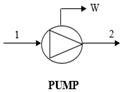
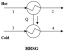
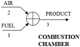
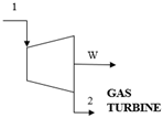
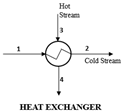
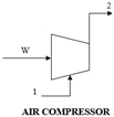
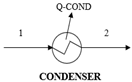
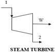
Figure 1 presents a trigeneration plant system integrated with a cascaded steam-to-steam power plant, an NH3-H2O driven VAR plant, and a district heating system. The gas turbine powers the trigeneration system and delivers electricity while the high-temperature exhaust heat is recovered to energize the combined steam-to-steam cascaded power plant, the VAR cooling, and the district heating. In the gas turbine assembly, the axial air compressor admits and raises atmospheric air to high temperatures and pressures into the combustion chamber; here, the fuel and compressed air produce hot gas, driving the gas turbine for electricity generation. Gas turbine exhaust heat is recovered in an HRSG and used for generating steam for the cascaded steam turbines. In the steam power cycle, the condensate pump sends water at atmospheric temperature and pressure through the HRSG-A to produce steam, which expands across the turbine blades to produce mechanical work at a low pressure and generate electricity. Low-temperature steam from the steam turbine exit is condensed in the condensate heat exchanger (HRSG-B) to complete the cycle. The unrecovered thermal energy from HRSG-B powers the cascaded bottoming steam turbine in a repeated cycle. The generator in the NH3-H2O VAR system also takes its energy source from the gas turbine exhaust through the feed heat exchanger (FDHX).
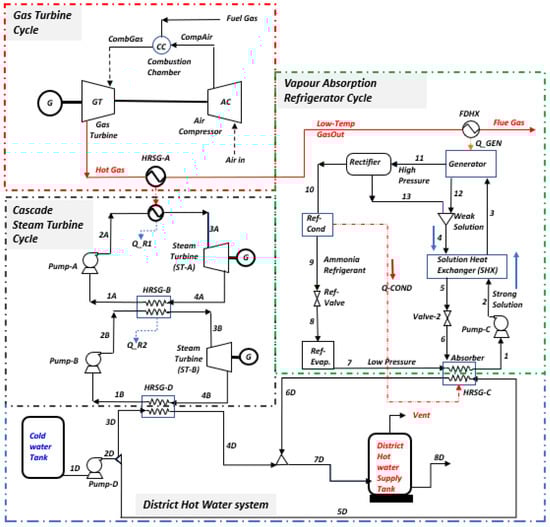
Figure 1.
Overview of the production process.
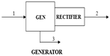
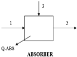
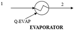
This single-effect VAR system utilizes water (H2O) as the absorbent and ammonia (NH3) as the refrigerant, comprising components like the generator, evaporator, condenser, absorber, rectifier, expansion valves, solution heat exchanger (SHX), and pump. In operation, the generator heats the rich NH3 solution with recovered FDHX heat, creating a weak solution. The resulting NH3 vapour travels through the rectifier, condenses in the high-pressure condenser (Ref. Cond), and then passes through the refrigeration throttle valve (Ref-Valve) to cool the evaporator (Ref. Evap). After extracting heat and evaporating, the low-pressure NH3 vapour moves from the evaporator to the absorber, where it is absorbed into a cold weak solution, forming a rich H2O solution of saturated NH3. A solution pump returns the rich solution to the generator for the NH3 vapour extraction process. The rectifier ensures the purification of the NH3-H2O cycle, preventing issues like hydrate formation and blockages. In the district heating system, wasted thermal energy rejected by the VAR and the cascade steam power cycle is harnessed and used to convert cool water to hot water for distribution to the district; thus, the energy efficiency of the integrated plant is improved.
3.1. Process Simulation
The system model, created via Aspen Plus V10, incorporates a trigeneration plant with gas and steam power generation, VAR cooling, and district heating systems. Utilizing the fluid property simulator in Table 2, the thermodynamic streams and properties for the entire system are determined. In the model, the air compressor is set at a compressor ratio of 10.1 to deliver high temperature and pressure compressed air to the gas turbine combustor. Fuel at 10 bar is injected into the combustor to form an explosive mixture in a stoichiometry process which delivers a hot mixture of 1250 °C at the gas turbine inlet to produce electricity. The hot exhaust gas exchanges heat with the HRSG (boiler) and FDHX generator, at 726 °C and 120 °C, respectively, to energize the cascaded steam power cycle and the VAR plants. The gas turbine exhaust temperature is set at 120 °C to prevent liquid retention and corrosion. The optimal performance of the HRSG relies on the complete conversion of the exhaust heat from the gas turbine. This involves setting the water flow rate in Aspen Plus to optimize the recovered heat and maintain optimal generated steam temperature and minimize potential residual heat loss (Q_Resid) in the HRSG. The steam produced is delivered at 50 bar and 264 °C to the topping steam turbine and delivers 40 MW of saturated thermal energy at the topping condenser (HRSG-B), which in turn energizes water at 35 bar and 243 °C on the cascaded bottoming steam turbine.
Table 2.
Integrated plant simulation input data.
The arrangement validated the supercritical nature of steam in power generation. The VAR generator contains a NH3-H2O mix in 67% and 33% compositions, respectively. The generator is energized from the gas turbine exhaust at 120 °C. The NH3-H2O VAR system uses a generator to produce high-pressure ammonia vapour. The vapour desorbs from a solution at 133 °C and pressure of 20 bar, condensing in the condenser (Ref. Cond) and expanding through throttle valve (Ref-Valve) to the low-pressure side in the evaporator (Ref. Evap). The low-pressure NH3 vapour then goes to the absorber, where it is absorbed by H2O-rich solution. The high-pressure weak H2O solution is produced through the solution heat exchanger (SHX), which preheats the weak solution by harnessing and exchanging heat from the hot strong solution. The solution, now rich in NH3, is pumped at 5.98 bar and 32 °C to the generator, completing the cycle.
Finally, the dissipated heat from the VAR plant as well as the heat from the cascade steam power plant (HRSG-D) is aggregated for internal heat recovery in the district heating cycle; thus, the heat dissipating devices are unloaded and the cycle efficiency is increased by pumping cooling water at atmospheric temperatures and pressures through the harnessed wasted heat exchangers. The water is energized as hot water for district water supplied at 88 °C. All the data required to develop this novel model are presented in Table 2.
3.2. Assumptions for the Thermodynamic System Models
The modelling of this system was performed by applying the mass balance, energy balance, and exergetic balance concepts [93] on all the components of the integrated plant systems, based on the assumptions specified below:
- Natural gas used is 100% methane delivered at 10.1 bar and 60 °C.
- Air at 25 °C is modelled as 21% O2 and 79% N2 molar mixture. Excess air is added at 20% to reach complete state of combustion.
- No pressure drops in the heaters or between components.
- The atmospheric temperature of water is 25 °C, which transitions to steam at 264 °C, zero superheat.
- Ambient condition: pressure, = 1.013 bar; temperature, = 25 °C.
- Components of the system are at steady-state and steady-flow conditions.
- In the VAR, the pressure in the condenser and absorber are equal, just as the pressure in the generator and evaporator are also equal.
- The enthalpy, , and entropy, , are 104.83 kJ/kg and 0.3672 kJ/kg-K, respectively, in the dead-state condition.
- The VAR refrigerant leaves the generator in a pure-state condition.
- The saturated solution mixture leaving the generator and absorber have the same temperature and concentration as the mixture in both vessels.
- Saturated water is the refrigerant in the condenser and the evaporator refrigerant is the saturated vapour at condensation, with the evaporator temperature and pressure, respectively.
- The throttling work is isenthalpic and no heat loss to the environment occurs.
- Kinetic exergy, chemical exergy, and potential exergy are all negligible.
3.3. Mathematical Models of Energy and Exergy Analysis
To ascertain the impact of the first and second laws of thermodynamics on the plant components, the systems are modelled. This takes us to the principal correlation of equations of mass and energy conversation of the first law, as shown in Equations (1) and (2), respectively.
By applying the first law of thermodynamics in the model control volume (CV) in a steady-state fluid flow regime [6], Equation (1) can be interpreted as Equation (2)
where , (kg/s), represents the mass flow; the specific enthalpy is h, (kJ/kg); Q represents the heat transfer rate (kW). is rate of work carried out (KW) and Ė also represents the energy rate (KW).
The system energy balance is evaluated to calculate the power generated, the consumption of fuel, and the energy efficiency of the various components of the systems. The air compressor power and the efficiency (isentropic) are evaluated using Equations (3) and (4), respectively.
To analyse the entropy changes for perfect gases in the air compressor, we have
where and are enthalpy and entropy, respectively, at the atmospheric pressure and temperature , respectively; and the specific heat, , is at a constant pressure.
At a constant pressure, natural gas is ignited in the air mixture in the gas turbine combustor, leading to a temperature rise at the combustor exit stream. The energy rate balance in the combustor is given as Equation (6).
And the exhaust gas pressure can be obtained from the combustor pressure drop.
For the gas turbine, the change in entropy in this isentropic process is given as:
where the pressure ratio of the turbine is .
Thus, the gas turbine power output is given as Equation (9):
The efficiency (isentropic) of gas turbine is given as Equation (10):
And the net power output of gas turbine is estimated as shown in Equation (11):
The gas turbine specific fuel consumption [94] is also obtained as shown in Equation (12a):
where represents the mechanical efficiency of gas turbine and the air/fuel ratio (AFR).
The specific steam consumption, i.e., the quantity of steam that is required to deliver electricity of 1 kWh, is determined using Equation (12b):
Furthermore, the exergetic balance equation, entrenched in the thermodynamic second law, is defined [95] though Equation (13):
Exergy expresses the maximum useful work potential in an energy stream that has a relationship with its environment [6]. The principal equation of the exergy balance of the thermodynamic second law is given by Equation (14):
Exergy due to heat transfer can also be expressed based on the Carnot factor, as shown in Equations (15) and (16), respectively.
And the entropy generated is defined as shown in Equation (17):
Substituting Equations (15) and (16) into Equation (14) defines the exergy destruction, as expressed in Equation (18):
Exergy is also described in relation to kinetic, potential, chemical, and physical exergy [33,96]. In this study, KE = PE = 0. The chemical exergy value will also be zero, since no chemical substance (loss or gain) is observed migrating to the environment from the system [97]. Thus, the total exergy of a system is given as Equation (19).
The physical component of the total exergy, as expressed in Equation (19) (by Alirahmi et al. [96]) is shown in Equation (20):
where , , , T, s, and h are temperature, entropy, and enthalpy, at the surrounding (subscript ‘o’) and system, respectively.
Most thermal-power-generating systems operate in a steady state, except in rare cases of the start-up and shutdown periods [98]. This is because non-steady-state periods are usually transient relative to steady-state operations. Therefore, balance equations for power-generation systems typically correspond to steady-flow and steady-state cases [99]. The energetic and exergetic assessment of the trigeneration plant incorporated with cooling and heating systems require the use of the thermodynamics first and second laws whose correlations are presented as shown in Appendix A Table A2. The chemical fuel exergy is described by Equation (21):
The chemical exergy in the combustor results from the migration of chemical components in the combustion system, a typical behaviour in combustion processes [98]. It is important to emphasize that, unlike energy, exergy is not governed by the law of conservation and is liberated during these processes [83]. Therefore, the total molar chemical exergy of the mixture of ideal gases is given by [44,100,101].
where is the specific chemical exergy of the k component material; are the mole fraction of each k component of combustion products at in the environment; is the specific gas constant.
Equation (23) was used to calculate the chemical exergy of various fuels as the ratio of fuel exergy to fuel lower heating value (LHV) [102,103,104].
For many hydrocarbon fuels, φ = 1. For example, methane gas has a value of about 1.06 and hydrogen has a value of 0.985 [102]. For the gaseous fuel categories with the content , the ratio, φ, may be evaluated by Equation (24) [105].
And the correlation for liquid fuels such as is provided by Szargut et al. [106] based on their atomic compositions, as follows:
The clean natural gas fuel used for analysis in this thesis contains CH4, C2H6, and C3H8 [6,88]. Based on unity (1) kmol of gas, the combustion equation of natural gas is governed by Equations (25b–d) and the amount of stoichiometric oxygen needed is calculated in Aspen plus, for the listed chemical reactions, as shown:
The stoichiometric or theoretical air is the minimum amount of air needed for the fuel combustion process. This typically leads to the harmful release of CO; therefore, it is appropriate to supply more than theoretical air to ensure complete combustion. The standard measure of the oxygen used in this model is put at 20% excess air [107] to reach the optimum air/fuel ratio using Equation (27). Therefore, the corresponding air mass flow of 346 kg/s (11.43 kmol/s) is needed for combustion of 16 kg/s (1 kmol/s) of methane gas. The stoichiometric air/fuel ratio (or theoretical AFR) is given in Equation (26). However, the excess air required is expressed by Equation (27).
where represents the number of moles of oxygen (O2); fexcess represents the percentage of excess air required.
For the VAR cooling system, the mass balance of the refrigerant is given as the mass flow rates of the strong solution and the weak solution, calculated as Equation (28):
where X is NH3 mass or mole fraction in the solution. The balance equation for the strong solution and the weak solution is also obtained from Equations (29) and (30), respectively.
The circulation ratio is defined as the mass fraction of the flow rate that relates the streams of the strong solution to that of the refrigerant [100] and it is presented as Equation (31):
The energetic and exergetic COP of the VAR system can be denoted in Equation (32) as the ratio of the evaporator energy gained to the energy supplied in the generator and the pump work output in the system [101]. The energetic COP is presented as in Equation (32).
where represents the evaporator energy output; represents the generator energy input; represents the pump work.
The maximum efficiency that is possible for a VAR, , is shown in Equation (33):
The expression is the Carnot refrigeration system, ; the expression is the Carnot engine efficiency, . Therefore, an ideal VAR system may be defined as a combination of a Carnot engine and a refrigeration system, which is equivalent to the maximum COP of a VAR system, postulated as Equation (34):
The exergy COP is defined [108] as presented in Equation (35):
Now, considering that the heat loss to the surroundings is negligible, the total energetic balance of the integrated system is given in Equation (36).
The solution heat exchanger (SHX) allows the transfer of heat from stream 4 (hot product from the generator) to stream 2 (cold stream in the outlet of the pump). However, the temperatures of streams 3 and 5, which remain unknown, would have to be determined via HEX effectiveness, using Equation (37).
This determines either of the unknown temperatures of T3 or T5. Thus, all heat transfer quantities are defined. Energy efficiency is defined as Equation (38):
While the exergetic efficiency is defined as shown in Equation (39):
The exergetic efficiency of a power plant is given in Equation (40):
For a VAR system, the exergetic efficiency is defined as shown in Equation (41):
where and are the generator and ambient temperatures, respectively.
3.4. Model Validation
In validating the model, a comparison is made between the data in the literature and the present model, as shown in Table 3. Discrepancies may arise from differences in data quality and boundary conditions. The integrated plant in the literature includes an ORC system, diverging from the present model’s cascading steam-to-steam power cycle, contributing to variations in results. Table 4 presents the energy and exergy balance of integrated plant components. Compressor, gas turbine, and steam turbine components exhibit high energy efficiency at 100%. The condenser, crucial for recovering intended dissipated heat, contributes to district heating with an efficiency of 88 °C and 150 kg/s of hot water. Notably, the cascaded HRSG-A and HRSG-B recover about 80% and 82% of potential energy losses in their respective condensers, into HRSG-D, where the temperature of the district heating system had been raised to enhance the overall system efficiency.
The efficiency of a condenser based on energy may be non-intuitive or even misleading since it does not account for irreversibility [109]. Only about 20% and 18% of recovered heat is utilized by the cascaded steam power plant, generating 10.35 MW and 7.63 MW of electricity in the topping and bottoming cycles, respectively. The total exhaust heat energy recovered from the gas turbine is 51.24 MW via HRSG-A and 0.32 MW via FDHX to power the VAR system. Approximately 6.39 MW of heat energy is lost as flue gas to the atmosphere. Despite the system’s steam-production capability, integrating VAR and district heating enables cooling and heating effects. The refrigeration output is 2.03 MW with a COP of 0.67, while the VAR system achieves a COP of 0.67 at an effectiveness of 0.70 [51]. The maximum COP obtained is 1.39 with a circulation ratio of 2.03. The VAR’s performance aligns with similar models, as shown in Table 3 and Table 4.
Table 3.
Comparison of the data in the literature with the analytical results of this model.
Table 3.
Comparison of the data in the literature with the analytical results of this model.
| Parameter | [104] | Reference | This Work | |
|---|---|---|---|---|
| Gas turbine | Gas turbine output (MW) | 95 | 94 | 50 |
| Gas turbine exit temperature (°C) | 532 | 532 | 726 | |
| Fuel mass flow rate (kg/s) | 6.8 | 6.7 | 3.0 | |
| ORC section | Mass flow rate produced (kg/s) | 82.9 | 82.3 | N/A |
| Evaporator outflow temperature (°C) | 110.5 | 110.4 | N/A | |
| ORC turbine outflow temperature (°C) | 60.8 | 61.3 | N/A | |
| Steam section | Mass flow rate produced (kg/s) | - | - | 34.4 |
| Evaporator outlet temperature (°C) | - | - | 264 | |
| Turbine exit temperature (°C) | - | - | 100 | |
| Refrigeration system | Generator heat load (kW) | 275.1 | 275.1 | 3057 |
| Evaporator heat load (kW) | 63.2 | 62.7 | 2071 | |
| Coefficient of performance exergy | 0.23 | 0.227 | 0.206 | |
| Refrigerant mass flow rate (kg/s) | 0.05 | 3.47 | ||
| Effectiveness of heat exchanger (ε) | 0.7 | 0.7 | 0.70 | |
| Generator temperature (°C) | 100 | 133 | ||
Reference: Gas turbine cycle [104]; ORC section [110]; refrigeration system [50].
Table 4.
Datasheet relevant for the integrated plant performance.
Table 4.
Datasheet relevant for the integrated plant performance.
| Plant Performance Cycles Data | ||
| Parameter | Gas Turbine Plant | Cascade Steam Plant |
| Thermal energy efficiency [%] | 76.68 | 38.45 |
| Cycle exergy efficiency [%] | 37.71 | 56.19 |
| Combined efficiency [%] | 85.05 | 77.99 |
| Air standard energy efficiency [%] | 48.21 | |
| Back work ratio (BWR) | 0.92 | 0.99 |
| Specific fuel consumption [kg/MWh] | 1052.36 | |
| Steam specific consumption [kg/MWh] | 1.93 | |
| Combustion efficiency [%] | 98.00 | |
| Datasets for the cooling and heating cycle performance | ||
| Parameter | VAR cooling | District Heating |
| COP [%] | 67.11 | |
| COPMAX | 1.39 | |
| Carnot Efficiency of VAR [%] | 76 | |
| COP Exergy [%] | 58.70 | |
| Circulation ratio | 2.03 | |
| Mass of strong solution [kg/s] | 3.47 | |
| Mass of Weak solution [kg/s] | 1.76 | |
| Cooling/heating capacity [MW] | 3.22 | 38.58 |
| Energy efficiency [%] | 99.87 | 100.00 |
| Exergy efficiency [%] | 92.25 | 77.66 |
| Effectiveness | 0.70 | |
4. Results and Discussions
4.1. Discussions on the Energy Analysis of the Integrated Plant
The simulation (Appendix A Figure A5) shows how important the binary steam-to-steam cycle is to the integrated trigeneration plant’s ability to recover thermal energy for district heating and VAR cooling. Employing Aspen Plus v10, the thermodynamic data of the process streams have been determined (Appendix A Table A1); the model applies thermodynamic laws to analyse energy balance and exergetic performance. Specifically, the gas turbine generates 50 MW at a combustor temperature of 1250 °C [111], simultaneously losing 65.2 MW of heat in a non-adiabatic condition. HRSG-A plays a crucial role by demanding 51.24 MW from the 726 °C gas turbine exhaust. This thermal energy is utilized to convert water to steam, supplying the steam turbine at 264 °C. Further details, including fluid properties and comprehensive results, are provided in Table 2 and Table 5, respectively.
Table 5.
Fuel, product, and efficiency performance of the integrated plant system.
The recovery of residual heat from the gas turbine exhaust significantly boosted overall power production by over 50%, resulting in a total system-generated power capacity of 44.08 MW. The recovered power from the gas turbine exhaust, facilitated by the feed heat exchanger (FDHX), drove the VAR generator, contributing 0.32 MW. The cascaded steam-to-steam cycle condenser and VAR cooling system condenser rejected 33.43 MW and 5.16 MW of thermal energy, respectively. This energy was converted to supply 150 kg/s of hot water at 88 °C to the district. The VAR generator, operating at 20.1 bar pressure, dropped to 5.98 bar after passing through the expansion valve, gaining 2.07 MW of cold energy in the evaporator at 13 °C. The weak recirculating solution in the solution heat exchanger (SHX) achieved 70% efficiency, transferring 1.523 MW of heat to the strong stream solution. The integrated plant performance is detailed in Table 4, showing gas turbine and combined steam turbine efficiencies of 85.05% and 57.89%, respectively. The cascade steam-to-steam cycle efficiency is 38.45%, with a specific steam consumption (SSC) of 51.24 MWh, indicating the steam power cycle’s efficiency.
The gas turbine combustion efficiency was set at 98%. However, the combustor had been limited in a non-adiabatic case to a temperature of 1250 °C. Thus, a heat loss of 65.2 MW from the combustor to the surrounding area occurs, as shown in the Sankey energy diagram presented in Figure 2. Aspen Plus v10 software was used to determine the natural gas (methane) calorific value used in this model as 50,035 kJ/kg. The energetic balance of the complex thermal plant system is carefully summarized, as presented in the Sankey energy diagram of Figure 2.
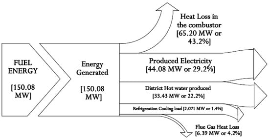
Figure 2.
Sankey energy diagram for the integrated system.
It is demonstrated that the system’s primary energy source is chemical fuel energy. Here, 29.2% (44.08 MW) of the fuel chemical energy is expended to produce electric power, 22.2% (33.43 MW) is expended to produce district hot water, and 1.4% (2.07 MW) is expended as a cooling load for the refrigeration system. About 43.2% (65.20 MW) and 4.2% (6.39 MW) are lost to the environment through the combustor and as flue gas. The relations between the compressor pressure ratio and the Brayton cycle air standard efficiency are also reviewed [94]. The chart in Figure 3 shows that the gas turbine cycle efficiency is largely reliant on pressure ratio, especially as the pressure ratio increases with the cycle efficiency.
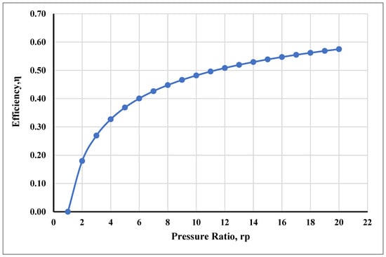
Figure 3.
Efficiency of the gas turbine vs. pressure ratio.
It also showed that the cycle efficiency is low at low pressure ratios, which has a comparable impact on the network output; this is because, in the gas turbine cycle, efficiency tends toward zero (0) as the pressure ratio tends toward one (1). This suggests that there will not be any heat added and that the network output figure will be zero. The cold air standard efficiency in this type at a 10:1 pressure ratio [112] gave an energy efficiency of 48.2%. However, the compressor temperature of the inlet air depends on the temperature of the surroundings, just as the inlet temperature (max) of the turbine gas is limited to 1250 °C due to the limitations of available metallurgy and the turbine blade’s heat-resistant properties. So, at the maximum temperature (Max), the pressure ratio also reaches the maximum limit, as does efficiency.
Figure 4 depicts the relationship between the combustion temperature and the pressure ratio. In the chart, the combustion temperature correlates with the compressor pressure ratio, displaying a proportional increase. To mitigate high-temperature issues in the combustor, including metallurgical concerns, the model constrained the combustion chamber to achieve a temperature of approximately 1250 °C at a compression ratio of 10. This restriction, influenced by internal material limitations, resulted in the release of 65.2 MW as heat loss from the combustor.
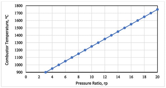
Figure 4.
Gas turbine combustion temperature vs. pressure ratio.
4.2. Discussion on the Exergy Analysis of the Integrated Plant
Table 5 provides a summary of the fuel exergy, product exergy, and exergetic efficiency for the combined-cascaded trigeneration, integrated VAR cycle, and district heating systems. The table also presents the overall exergy and energetic efficiency, along with the destroyed exergy of the components in the integrated plants. The cumulative energetic and exergetic efficiencies of the complex thermal plant cycles are determined at 85.05% and 77.99%, respectively, and consist of the gas turbine cycle (76.68% and 37.71%), the cascaded steam power plant cycle (38.54% and 56.19%), the VAR cooling cycle (99.87% and 92.25%), and district heating system (100% and 77.66%).
The overall exergetic destruction within the entire system amounts to 50.36 MW see Figure 5 and has been illustrated with the Grassmann exergetic analysis map in Figure 6, with the gas turbine cycle being the major contributor to exergetic destruction, specifically the combustor chamber, accounting for 52% of the total destruction. The significant exergetic destruction in the combustor may result from factors such as chemical reactions, elevating the chamber temperature to 1250 °C, potential incomplete combustion, and thermal energy loss to the environment [113]. Heat loss in the combustor can be mitigated using thermally resistant ceramic insulation. However, uncontrolled high temperatures may lead to destructive adiabatic flame, causing thermal stress [6]. Improving gas turbine cycle efficiency involves preheating the air compressor’s inlet with recovered hot air from the turbine exhaust and modifying the turbine into high-pressure (HPT) and low-pressure (LPT) versions with an inter-stage reheater for enhanced output power and efficiency.
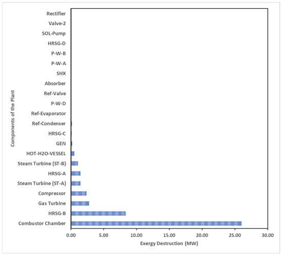
Figure 5.
Overhaul destruction of exergy in the integrated plant.
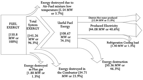
Figure 6.
Grassman exergy diagram for the integrated plant.
The HRSG-B accounts for approximately 17% of the total destroyed exergy in the cascade steam power plant system, primarily due to its steam-to-steam cascade system’s recovery of substantial heat energy. In contrast, HRSG-A contributes only 3% with its lower energy efficiency. The gas turbine and its air compression units experience significant exergy destruction, attributed to gas expansion in the turbine blades and energetic losses in the air compressor resulting from high-pressure ratios. The system’s irreversibility is fundamentally linked to abrupt temperature differentials in the flowing streams, highlighting the importance of addressing these challenges for enhanced efficiency [114].
4.3. Exergetic Destruction of the Integrated Plant
The combustor contributes to about 83% of the cumulative exergy destruction in the gas turbine (Brayton) cycle plant, while the air compressor and gas turbine account for 8% and 9%, respectively, as depicted in Appendix A, Figure A1. In Appendix A, Figure A2, illustrating the cascaded steam-to-steam power plant cycle, condensers exhibit dominance in exergy destruction over other components. This behaviour is typical, primarily attributed to heat transfer or heat loss between turbine exhaust steam and pump inlet saturated water, driven by the high enthalpy of condensed water compared to the exhaust steam enthalpy, potentially involving latent heat loss to the environment.
The exergy destruction in the steam-to-steam cascade plant is primarily attributed to the HRSG and condensers, contributing 55% and 31%, respectively. The condenser’s destruction, though significant energetically, is negligible in exergy terms, as it efficiently converts thermal energy into hot water for the district. The HRSG’s exergy destruction is linked to a finite temperature differential (726 °C to 124 °C), increasing irreversibility and generating entropy in the flue gas stream. Energy destruction in both pumps is minimal compared to other components. In contrast, exergy destruction in the cascaded steam turbines is associated with the pressure drop during the expansion process, impacting turbine blade efficiency and reducing the useful work carried out by the turbine. Table 4 provides a comprehensive overview of the exergetic performance of the integrated plant system’s VAR cooling cycle. While Table 4 already outlines the calculated values for the VAR system’s performance coefficient, COP, exergetic efficiency, and exergetic COP, Table 5 delves into the exergy assessment of the individual components within the VAR (NH3–H2O absorption) system.
The thermodynamic model of the plant allows for an investigation of various performance criteria based on parameter variations, including thermal source and sink temperatures, plant component energy outputs, and other evaluations such as the total destruction of exergy and individual component destruction of exergy, graphically presented in Appendix A, Figure A3. The inefficiencies in the VAR system can be attributed to factors such as finite heating, mixing, circulation losses, and mass transfer. Notably, the generator contributes approximately 36% (0.2 MW) to the destruction rate of energy in the VAR system. Following in the hierarchy are the refrigerant condenser at 25% (0.14 MW) and the evaporator at 17% (0.09 MW). The high destruction of exergy in the generator is likely due to mixing losses resulting from the heat generated by the mixture of strong solution and ammonia vapour within the components. Additionally, the rectifier and the expansion valves (VALV-2) exhibit decreasing exergy destruction as temperature rises to 133 °C towards the absorber, attributed to a zero-pressure drop in the rectifier and constant enthalpy observed across the expansion valve (VALV-2).
The destroyed exergy in the refrigerant condenser, refrigerant valve (Ref-valve), and the evaporator is influenced by the high temperature of the generator, leading to variations in the total exergetic rate destroyed in the system. Of the exergy destruction in the Ref-Condenser, 25% (0.14 MW) may be attributed to the high temperature change across the condenser due to rapid cooling and condensation of the refrigerant, mass transfer, and thermal energy losses associated with varying high-temperature approaches. Measures to reduce exergy destruction include operating the system at a higher sink temperature or a lower bottom generator temperature. A proportion of 13% of the exergy destruction in the Ref-Valve, despite zero enthalpy changes, may result from the pressure drop during the generator pressure reduction from 20.1 bar to 5.98 bar into the pump suction. The reception of cold energy in the evaporator significantly impacts its exergetic efficiency.
In this paper, the exergy destruction ratio for most components of the VAR system is relatively small compared to other thermal systems in the plant. The exergetic coefficient of performance provides insights into the system’s exergetic losses. The energetic destruction in the overall VAR system increased to 1.19 MW at a high evaporator temperature of 17 °C due to the elevated energy intake in the evaporator at a generator temperature of 148 °C. Consequently, the exergetic COP decreases with an increase in generator temperature (see Figure 7). The assumed drop in pressure between the generator and the condenser in the model is zero. It is also observed that exergetic losses in the condenser increase with the rise in generator temperature.
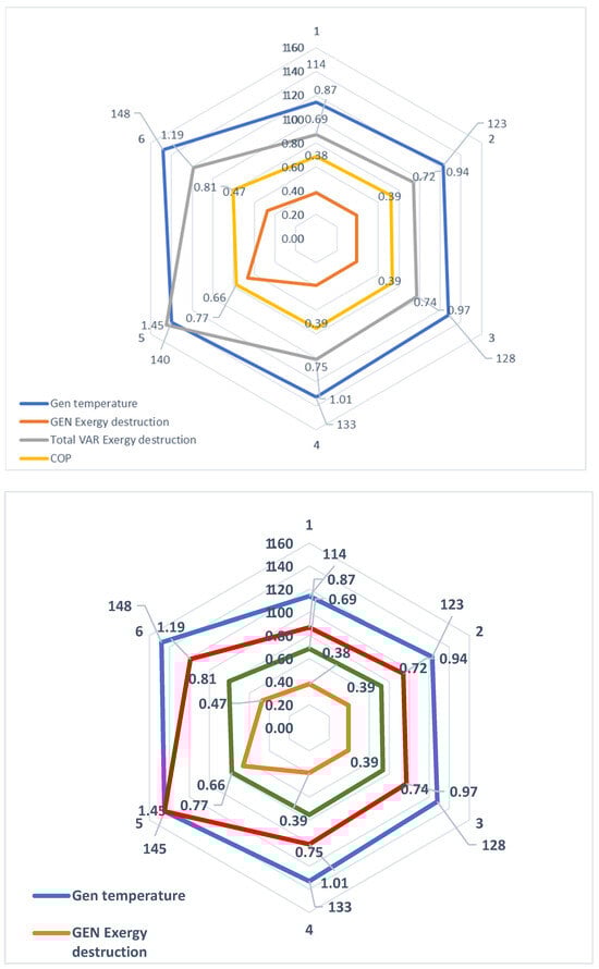
Figure 7.
Effect of exergy destruction on the generator.
Conversely, as the generator temperature decreases, the condenser exergetic destruction trends downward. The maximum condenser exergy loss at a 133 °C generator temperature is 0.14 MW. Figure 7 illustrates that, as the generator temperature rises, so does the exergy destruction in the generator, until a COP of 77% is exceeded; at this point, the exergy destruction begins to decrease. At a generator temperature of 140 °C, exergy destruction increased to 1.45 MW and dropped to 1.19 MW, with a further increase in the generator temperature to 148 °C. Appendix A Figure A4 displays the exergetic assessment of the district’s water-heating system. Notably, the hot water vessel exhibits the highest exergy destruction, operating at 0.5 MW and a high temperature of 88 °C, following a substantial pressure drop from 40 bar to 2 bar. HRSG-C recovers heat energy from various heat sinks, including the VAR absorber and refrigerant condenser, while HRSG-D captures heat energy from the cascaded condenser B in the steam power plant system. All recovered thermal energy is utilized to heat cold water, subsequently distributed as hot district water, effectively minimizing energy losses in the integrated plant and further enhancing the destruction of exergy in the district’s water-heating system. Additionally, the pump’s exergy loss of 13% is noteworthy due to the high flow rate of discharged cold water. In summary, the district’s hot-water-heating tank contributes about 72% of exergy destruction in the entire district’s water-heating system, as shown in Appendix A Figure A4.
Figure 8 illustrates the energetic and exergetic efficiencies of individual components in a bar chart format. The cumulative energetic and exergetic efficiencies of the integrated plant are found to be 85.05% and 77.99%, respectively. This performance is attributed to the minimal thermal energy impact on the VAR plant components compared to the combined-cascade thermal cycle plant.
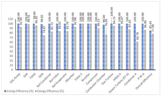
Figure 8.
Component and overall efficiency of the integrated plant.
A key result from the integrated plant model analysis highlights that the gas turbine combustor is the primary site of exergy destruction, followed by HRSG-B and the gas turbine itself (Figure 5). This aligns with findings from similar analyses conducted in other thermal system studies [37,103,115,116,117]. Notably, many components in the integrated plant exhibit near-zero exergy destruction, emphasizing that the VAR system components experience minimal thermal impact compared to those in the combined-cascaded cycle. Importantly, the study underscores the improved overall exergetic performance of the thermal system model due to the utilization of heat sink points for converting cold water to hot district water, in contrast to the rejection of heat to the environment.
5. Conclusions
This study investigated the exergetic performance of an integrated cascade trigeneration power system, incorporating ammonia–water mixture vapour absorption refrigeration (VAR) cooling and district heating. With a growing global demand for sustainable energy solutions, the focus is on efficient energy resource utilization. The use of the second law of thermodynamics and exergetic tools offers valuable insights into energy quality, efficiency, and process optimization. Unlike the first law, which evaluates processes, measuring available useful work or energy quality is crucial for designing new systems and improving the efficiency of existing ones.
This study suggests that the combined-cascade cycle for energy conversion could be a pathway to global energy security. It demonstrates the unique advantages of this approach over other thermal-power-generation systems [118], justifying the motivation behind the research. The work highlights the supercritical potential of water as a working fluid in a combined-cascade cycle thermal system, contributing to the exploration for efficient, affordable, and environmentally friendly heat-transfer fluids. The adaptation of the steam-to-steam working fluids concept holds potential benefits for the power industry by addressing cost and scarcity issues associated with ORC working fluids.
The integrated cascade cycle plant includes a vapour absorption refrigeration system for large-scale refrigeration and heating water production, aiming to optimize recoverable heat and minimize energy waste [119]. Operating independently, this system achieved cooling and heating capacities of 2.07 MW and 38.62 MW, respectively, with high efficiency (92.25%) and minimal exergetic losses. The gas turbine cycle achieved energy and exergy efficiencies of 76.68% and 37.71%, respectively, and the cascaded steam-to-steam power plant reached an energetic efficiency of 38.45% and an exergy efficiency of 56.19%. The overall cycle efficiencies, reflecting optimal energy utilization, were 85.05% (energy) and 77.99% (exergy). However, exergetic destruction in the integrated plant was noted at 50.36 MW (33% of energy generated), with the gas turbine combustor contributing 50% to the destroyed exergy.
The achieved efficiency of 56.19% in the combined-cascade cycle is notably high for thermal-power-generation systems. Unlike many cascaded ORC or steam systems, the thermal efficiency of steam-powered systems [119] is generally low. The study highlights the efficient utilization of waste heat recovered from the gas turbine (Brayton) cycle, resulting in an additional power capacity of 17.98 MW (69% of the 26 MW generated by the gas turbine) from the cascaded system. The optimization and utilization of heat sink points in the system, converted into district heating water, contribute to the overall improved exergetic performance compared to the traditional approach of rejecting heat energy to the environment.
Author Contributions
Conceptualization, methodology, writing—original draft preparation, L.O.A. and P.A.A.; methodology, S.C.N.; software and investigation, F.O.; validation, visualization, project administration, and software, O.D.S. and T.B.; visualization and formal analysis, O.D. and A.E.; resources and investigation, R.S. All authors have read and agreed to the published version of the manuscript.
Funding
Thus research received no external funding.
Data Availability Statement
Data are contained within the article.
Conflicts of Interest
The authors declare no conflict of interest.
Abbreviations
| CCPP | combined-cycle power plants |
| Comp | compressor |
| COP | coefficient of performance |
| FDHX | feed heat exchangers |
| GWP | global warming potential |
| HEP | hydroelectric power |
| HEX | heat exchangers |
| HFC | hydro-fluorocarbon |
| HRSG | heat recovery steam generation |
| kBD | thousands of barrels per day |
| LNG | liquified natural gas |
| NGL | natural gas liquids |
| ORC | organic Rankine cycle |
| SHX | solution heat exchanger |
| VAR | vapour absorption refrigeration |
| VCS | vapour compression system |
| MBE | mass balance equation |
| EBE | energy balance equation |
| ExBE | exergy balance equation |
| Ref.Cond | refrigerant condenser |
| Ref.Evap | refrigerant evaporator |
| Ref.Valve | refrigerant valve |
| CV | control volume |
| LHV | lower heating value (MJ/kg) |
| HHV | higher heating value (MJ/kg) |
| Subscripts | |
| ac | air compressor |
| CHM | chemical |
| cc | combustion chamber |
| D | destruction |
| F | fuel |
| in | inlet streams |
| k | kth component of system |
| o | reference state |
| Out | outlet stream |
| P | product |
| PHY | physical |
| th | thermal |
| tot | total |
| Nomenclature | |
| Ė | energy rate [kW] |
| Ex | exergy rate [kW] |
| ex | specific exergy rate of material streams (kJ/kmol) |
| ExD | exergy destruction rate |
| ExL | exergy loss rate |
| hi | specific enthalpy at initial state (kJ/kmol) |
| ho | specific enthalpy at reference state (kJ/kmol) |
| KE | kinetic energy |
| ṁ | mass flow rate [kg/sec] |
| ṁFuel | mass flow rate of Fuel [kg/sec] |
| P | power output [kW] |
| Po | pressure at reference state (atm) |
| PE | potential energy |
| Q | heat flow rate |
| Si | specific entropy at initial state (kJ/kmol) |
| So | specific enthalpy at reference state (kJ/kmol) |
| To | temperature of reference state (K) |
| WBlowr | blower power (kW) |
| WExp | expander power (kW) |
| WNet | net power (kW) |
| WP | pump power (kW) |
| WTurb | steam turbine power (kW) |
| yD | exergy destruction rate ratio |
| Greek letters | |
| φ | coefficient from the liquid fuel expression |
| ηĖ | energy efficiency |
| ηex | exergy efficiency |
| ηPump | pump efficiency |
| ηth | thermal efficiency |
Appendix A
Table A1.
Thermodynamic properties of the integrated plant streams.
Table A1.
Thermodynamic properties of the integrated plant streams.
| Units | Temperature [C] | Pressure [bar] | Mass Flows [kg/sec] | Mass Density [kg/cum] | Mass Enthalpy [kJ/kg] | Mass Entropy [kJ/kg-K] | Heat Flow [MW] | Volume Flow [m3/s] | Mass Exergy [kJ/kg] | Exergy Flow Rate [MW] |
|---|---|---|---|---|---|---|---|---|---|---|
| VAR Cooling System | ||||||||||
| 1.00 | 31.76 | 5.98 | 3.47 | 710.25 | 8088.55 | 10.03 | 28,076.18 | 0.00 | 79.87 | 277.23 |
| 2.00 | 32.70 | 55.98 | 3.47 | 709.03 | 8080.26 | 10.00 | 28,047.43 | 0.00 | 80.45 | 279.27 |
| 3.00 | 126.72 | 55.98 | 3.47 | 305.26 | 7641.55 | 8.89 | 26,524.60 | 0.01 | 189.27 | 656.96 |
| 4.00 | 132.93 | 20.01 | 1.76 | 678.12 | 10,146.51 | 6.83 | 17,864.06 | 0.00 | 256.68 | 451.91 |
| 5.00 | 62.77 | 20.01 | 1.76 | 772.93 | 11,011.45 | 9.00 | 19,386.89 | 0.00 | 37.63 | 66.25 |
| 6.00 | 62.77 | 5.98 | 1.76 | 772.93 | 11,011.45 | 9.00 | 19,386.89 | 0.00 | 37.63 | 66.25 |
| 7.00 | 89.42 | 5.98 | 1.71 | 3.39 | 3372.36 | 5.88 | 5768.40 | 0.50 | 278.83 | 476.93 |
| 8.00 | 12.89 | 5.98 | 1.71 | 17.37 | 4583.04 | 9.79 | 7839.25 | 0.10 | 235.45 | 402.73 |
| 9.00 | 53.23 | 20.01 | 1.71 | 583.02 | 4583.04 | 9.94 | 7839.25 | 0.00 | 280.21 | 479.30 |
| 10.00 | 132.89 | 20.01 | 1.71 | 10.14 | 3275.80 | 6.21 | 5603.22 | 0.17 | 475.52 | 813.38 |
| 11.00 | 132.89 | 20.01 | 1.71 | 10.14 | 3275.80 | 6.21 | 5603.22 | 0.17 | 475.52 | 813.38 |
| 12.00 | 132.93 | 20.01 | 1.76 | 678.12 | 10,146.51 | 6.83 | 17,864.06 | 0.00 | 256.68 | 451.91 |
| 13.00 | 132.89 | 20.01 | 0.00 | 0.00 | 10,144.21 | 6.83 | 0.00 | 0.00 | 256.64 | 0.00 |
| Gas Turbine Cycle | ||||||||||
| AIR-IN | 26.85 | 1.01 | 68.39 | 1.17 | 1.60 | 0.15 | 109.26 | 58.49 | 0.01 | 0.40 |
| COMBGAS | 1250.00 | 10.00 | 71.39 | 2.19 | 769.30 | 1.29 | 54,917.63 | 32.53 | 1157.71 | 82,644.27 |
| COMPARE | 364.18 | 10.00 | 68.39 | 5.41 | 351.11 | 0.26 | 24,011.01 | 12.64 | 315.01 | 21,542.31 |
| FLUE-GAS | 120.00 | 1.01 | 71.39 | 0.86 | 2191.88 | 0.32 | 156,470.02 | 82.68 | 26.34 | 1880.08 |
| FUEL | 60.00 | 10.00 | 3.00 | 5.88 | 4575.10 | 5.98 | 13,725.29 | 0.51 | 355.16 | 1065.47 |
| GAS-OUT | 124.00 | 1.01 | 71.39 | 0.85 | 2187.44 | 0.33 | 156,152.72 | 83.52 | 27.43 | 1957.97 |
| HOTGAS | 726.13 | 0.99 | 71.39 | 0.33 | 1469.72 | 1.42 | 104,917.63 | 215.85 | 418.49 | 29,874.36 |
| Cascaded Steam-to-Steam Power System | ||||||||||
| 1A | 27.00 | 1.00 | 19.16 | 996.63 | 15,857.45 | 9.03 | 303,833.79 | 0.02 | 0.03 | 0.50 |
| 2A | 27.31 | 50.00 | 19.16 | 998.72 | 15,851.66 | 9.03 | 303,722.96 | 0.02 | 5.05 | 96.76 |
| 3A | 263.95 | 50.00 | 19.16 | 25.36 | 13,177.64 | 3.46 | 252,487.87 | 0.76 | 1017.57 | 19,496.97 |
| 4A | 99.62 | 1.00 | 19.16 | 0.73 | 13,717.90 | 3.20 | 262,839.40 | 26.40 | 401.06 | 7684.35 |
| 1B | 27.00 | 1.00 | 15.28 | 996.63 | 15,857.45 | 9.03 | 242,246.28 | 0.02 | 0.03 | 0.40 |
| 2B | 27.21 | 35.00 | 15.28 | 998.08 | 15,853.44 | 9.03 | 242,184.96 | 0.02 | 3.54 | 54.02 |
| 3B | 242.57 | 35.00 | 15.28 | 17.53 | 13,169.94 | 3.31 | 201,190.58 | 0.87 | 980.78 | 14,982.93 |
| 4B | 99.62 | 1.00 | 15.28 | 0.71 | 13,669.47 | 3.07 | 208,821.58 | 21.60 | 410.75 | 6274.82 |
| District Hot Water System | ||||||||||
| 1D | 25.00 | 2.00 | 150.00 | 997.21 | 15,865.70 | 9.06 | 2,379,855.57 | 0.15 | 0.12 | 17.64 |
| 2D | 25.23 | 40.00 | 150.00 | 998.85 | 15,861.22 | 9.06 | 2,379,183.11 | 0.15 | 4.01 | 601.02 |
| 3D | 25.23 | 40.00 | 120.00 | 998.85 | 15,861.22 | 9.06 | 1,903,346.49 | 0.12 | 4.01 | 480.82 |
| 4D | 92.01 | 40.00 | 120.00 | 965.59 | 15,582.68 | 8.22 | 1,869,921.79 | 0.12 | 31.41 | 3769.58 |
| 5D | 25.23 | 40.00 | 30.00 | 998.85 | 15,861.22 | 9.06 | 475,836.62 | 0.03 | 4.01 | 120.21 |
| 6D | 66.50 | 40.00 | 30.00 | 981.41 | 15,689.32 | 8.52 | 470,679.70 | 0.03 | 15.03 | 450.94 |
| 7D | 86.92 | 40.00 | 150.00 | 969.00 | 15,604.01 | 8.27 | 2,340,601.49 | 0.15 | 27.62 | 4143.25 |
| 8D | 87.63 | 2.00 | 150.00 | 966.77 | 15,604.01 | 8.26 | 2,340,601.49 | 0.16 | 24.29 | 3643.86 |
Table A2.
Table of components and balance equations.
Table A2.
Table of components and balance equations.
| Components | Balance Equations: |
|---|---|
 | MBE: ∑ |
| EBE: | |
| ExBE: | |
| Energy efficiency, | |
| Exergy efficiency, | |
 | MBE: ∑ |
| EBE: | |
| ExBE: | |
| Energy efficiency, | |
| Exergy efficiency, | |
 | MBE: ∑ |
| where | |
| EBE: | |
| where LHV = | |
| ExBE: | |
| Energy efficiency, | |
| Exergy efficiency, | |
 | MBE: ∑ |
| EBE: | |
| ExBE: | |
| Energy efficiency | |
| Exergy efficiency, | |
 | MBE: ∑ |
| EBE: | |
| ExBE: | |
| Energy efficiency, | |
| Exergy efficiency, | |
 | MBE: ∑ |
| EBE: | |
| ExBE: | |
 | MBE: ∑ |
| EBE: | |
| ExBE: | |
| Energy efficiency | |
| Exergy efficiency, | |
 | MBE: ∑ |
| EBE: | |
| ExBE: | |
| Energy efficiency, | |
| Exergy efficiency, | |
 | MBE: ∑ |
| EBE: | |
| ExBE: | |
| Energy efficiency, | |
| Exergy efficiency, | |
 | MBE: ∑ |
| EBE: | |
| ExBE: | |
| Energy efficiency, | |
| Exergy efficiency, | |
 | MBE: ∑ |
| EBE: | |
| ExBE: | |
| Energy efficiency, | |
| Exergy efficiency, | |
 | MBE: ∑ |
| EBE: | |
| ExBE: | |
| Energy efficiency, | |
| Exergy efficiency, | |
| Total exergy destruction in the VAP |
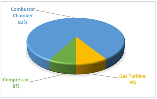
Figure A1.
Exergetic destruction in the gas turbine (Brayton) cycle.
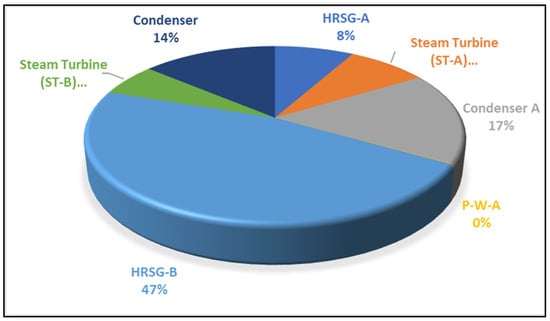
Figure A2.
Exergetic destruction in cascade steam power plant (Rankine) cycle.

Figure A3.
Exergetic destruction in vapour absorption refrigeration (VAR) cycle.
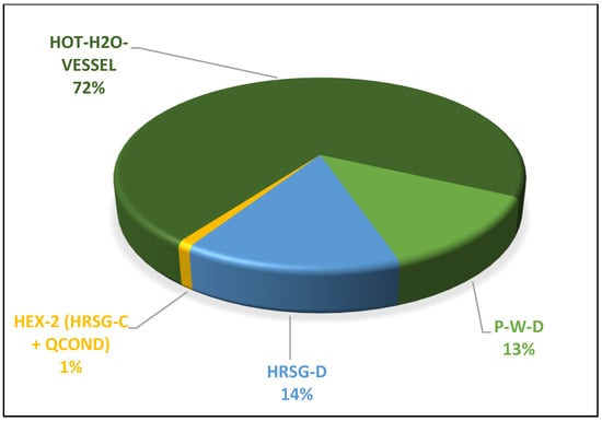
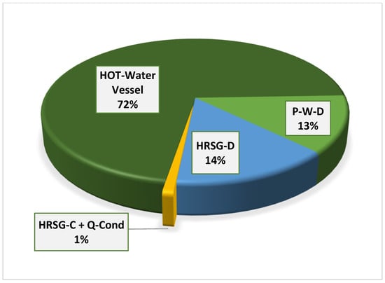
Figure A4.
Effect of exergy destruction on the district’s water-heating system.
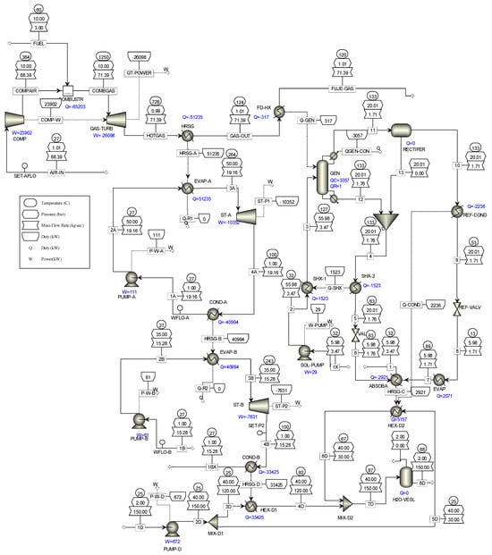
Figure A5.
Overall simulation of the integrated plant.
References
- IEA. Gas Market Report, Q1-2022; International Energy Agency: Paris, France, 2022. [Google Scholar]
- Dale, S. BP Statistical Review of World Energy, 71st ed.; BP Publications: Kolkata, India, 2022. [Google Scholar]
- IEA. COP26 Climate Pledges Could Help Limit Global Warming to 1.8 °C, but Implementing Them Will Be the Key; IEA: Paris, France, 2021. [Google Scholar]
- Holz, F.; Richter, P.M.; Egging, R. The Role of Natural Gas in a Low-Carbon Europe: Infrastructure and Regional Supply Security in the Global Gas Model; DIW Berlin—German Institute for Economic Research: Berlin, Germany, 2013. [Google Scholar]
- Petrakopoulou, F.; Boyano, A.; Cabrera, M.; Tsatsaronis, G. Exergoeconomic and exergoenvironmental analyses of a combined cycle power plant with chemical looping technology. Int. J. Greenh. Gas Control 2011, 5, 475–482. [Google Scholar] [CrossRef]
- Aigba, P.A.; Emovon, I.; Samuel, O.D.; Chintua, E.C.; Abdeljawad, T.; Al-Mdallal, Q.M.; Afzal, A. Exergetic Assessment of Waste Gas to Energy in a Novel Integrated NGL Recovery and Power Generation Plant. Front. Energy Res. 2022, 9, 798896. [Google Scholar] [CrossRef]
- Poullikkas, A. An overview of current and future sustainable gas turbine technologies. Renew. Sustain. Energy Rev. 2005, 9, 409–443. [Google Scholar] [CrossRef]
- Gonzalez-Salazar, M.A.; Kirsten, T.; Prchlik, L. Review of the operational flexibility and emissions of gas- and coal-fired power plants in a future with growing renewables. Renew. Sustain. Energy Rev. 2018, 82, 1497–1513. [Google Scholar] [CrossRef]
- Ibrahim, T.K.; Rahman, M.M.; Abdalla, A.N. Optimum Gas Turbine Configuration for Improving the Performance of Combined Cycle Power Plant. Procedia Eng. 2011, 15, 4216–4223. [Google Scholar] [CrossRef]
- González-Salazar, M.A. Recent developments in carbon dioxide capture technologies for gas turbine power generation. Int. J. Greenh. Gas Control 2015, 34, 106–116. [Google Scholar] [CrossRef]
- Bracco, S.; Silvia, S. Exergetic Optimization of Single Level Combined Gas Steam Power Plants Considering Different Objective Functions. Energy 2010, 35, 5365–5373. [Google Scholar] [CrossRef]
- Xiang, W.; Chen, Y. Performance Improvement of Combined Cycle Power Plant Based on the Optimization of the Bottom Cycle and Heat, Recuperation. Therm. Sci. 2007, 16, 84–89. [Google Scholar] [CrossRef]
- Briesch, M.S.; Bannister, R.L.; Diakunchak, I.S.; Huber, D.J. A Combined Cycle Designed to Achieve Greater than 60 Percent Efficiency. ASME J. Eng. Gas Turbines Power 1995, 117, 734–741. [Google Scholar] [CrossRef]
- Bassily, A.M. Modeling, Numerical Optimization, and Irreversibility Reduction of a Dual-Pressure Reheat Combined-Cycle. Appl. Energy 2005, 81, 127–151. [Google Scholar] [CrossRef]
- Koch, C.; Cziesla, F.; Tsatsaronis, G. Optimization of combined cycle power plants using evolutionary algorithms. Chem. Eng. Process. Process Intensif. 2007, 46, 1151–1159. [Google Scholar] [CrossRef]
- Ibrahim, T.K.; Mohammed, M.K.; Awad, O.I.; Rahman, M.; Najafi, G.; Basrawi, F.; Alla, A.N.A.; Mamat, R. The optimum performance of the combined cycle power plant: A comprehensive review. Renew. Sustain. Energy Rev. 2017, 79, 459–474. [Google Scholar] [CrossRef]
- Woudstra, N.; Woudstra, T.; Pirone, A.; Van Der Stelt, T. Thermodynamic Evaluation of Combined Cycle Plants. Energy Convers. Manag. 2010, 51, 1099–1110. [Google Scholar] [CrossRef]
- Khaleel, O.J.; Ismail, F.B.; Ibrahim, T.K.; Hassan, S.H.B.A. Energy and exergy analysis of the steam power plants: A comprehensive review on the Classification, Development, Improvements, and configurations. Ain Shams Eng. J. 2022, 13, 101640. [Google Scholar] [CrossRef]
- Elhelw, M.; Al Dahma, K.S.; Attia, A.E.H. Utilizing exergy analysis in studying the performance of steam power plant at two different operation mode. Appl. Therm. Eng. 2019, 150, 285–293. [Google Scholar] [CrossRef]
- Akiba, M.; Thani, E.A. Thermodynamic Analysis of New Combination of Supercharged Boiler Cycle and Heat Recovery Cycle for Power Generation. ASME J. Eng. Gas Turbines Power 1996, 118, 453–460. [Google Scholar] [CrossRef]
- Jericha, H.; Hoeller, F. Combined Cycle Enhancement. J. Eng. Gas Turbines Power 1991, 113, 198. [Google Scholar] [CrossRef]
- Bolland, O. A Comparative Evaluation of Advanced Combined Cycle Alternatives. ASME J. Eng. Gas Turbines Power 1991, 113, 190–197. [Google Scholar] [CrossRef]
- Seyedan, B.; Dhar, P.L.; Gaur, R.R.; Bindra, G.S. Optimization of Waste Heat Recovery Boiler of a Combined Cycle Power Plant. ASME J. Eng. Gas Turbines Power 1996, 118, 561–564. [Google Scholar] [CrossRef]
- Vidal, A.; Best, R.; Rivero, R.; Cervantes, J. Analysis of a combined power and refrigeration cycle by the exergy method. Energy 2006, 31, 3401–3414. [Google Scholar] [CrossRef]
- Walraven, D.; Laenenb, B.; D’haeselee, W. Minimizing the levelized cost of electricity production from low-temperature geothermal heat sources with ORCs: Water or air cooled. Appl. Energy 2015, 142, 144–153. [Google Scholar] [CrossRef]
- Suna, J.; Li, W. Operation optimization of an organic Rankine cycle (ORC) heat recovery power plant. Appl. Therm. Eng. 2011, 31, 2032–2041. [Google Scholar] [CrossRef]
- Esen, H.; Inalli, M.; Esen, M. Technoeconomic appraisal of a ground source heat pump system for a heating season in eastern Turkey. Energy Convers. Manag. 2006, 47, 1281–1297. [Google Scholar] [CrossRef]
- Esen, H.; Inalli, M.; Esen, M. A techno-economic comparison of ground-coupled and air-coupled heat pump system for space cooling. Build. Environ. 2007, 42, 1955–1965. [Google Scholar] [CrossRef]
- Wang, J.; Wang, M.; Li, M.; Xia, J.; Dai, Y. Multi-objective optimization design of condenser in an organic Rankine cycle for low grade waste heat recovery using evolution aryalgorithm. Int. Commun. Heat. Mass. Transf. 2013, 45, 47–54. [Google Scholar] [CrossRef]
- Chen, H.; Goswam, D.Y.; Stefanakos, E.K. A review of thermodynamic cycle and working fluids for the conversion of low-grade heat. Renew. Sustain. Energy Rev. 2010, 14, 3059–3067. [Google Scholar] [CrossRef]
- Dai, Y.; Wang, J.; Gao, L. Parametric optimization and comparative study of organic Rankine cycle (ORC) for low grade waste heat recovery. Energy Convers. Manag. 2009, 50, 576–582. [Google Scholar] [CrossRef]
- Ahmadi, G.R.; Toghraie, D. Energy and exergy analysis of Montazeri Steam Power Plant in Iran. Renew. Sustain. Energy Rev. 2016, 56, 454–463. [Google Scholar] [CrossRef]
- Marin, A.; Dobrovicescu, A.; Grosu, L.; Gheorghian, A. Energy and exergy analysis of an Organic Rankine cycle, UPB Sci. Bull. Ser. D 2014, 76, 127–136. [Google Scholar]
- Chua, H.T.; Toh, H.K.; Ng, K.C. Thermodynamic modeling of an ammonia–water absorption chiller. Int. J. Refrig. 2002, 25, 896–906. [Google Scholar] [CrossRef]
- Tamm, G.; Goswami, D.Y.; Lu, S.; Hasan, A.A. A Novel Combined Power and Cooling Thermodynamic Cycle for Low Temperature Heat Sources: Part I—Theoretical Investigation. Sol. Energy 2003, 125, 218–222. [Google Scholar] [CrossRef]
- Xu, F.; Goswami, D.Y.; Sunil, S.; Bhagwat, A. Combined power/cooling cycle. Energy 2000, 25, 233–246. [Google Scholar] [CrossRef]
- Goswami, D.Y. Solar Thermal Power: Status of Technologies and Opportunities for Research; Tata McGraw Hill: New Delhi, India, 1995; pp. 57–60. [Google Scholar]
- Zheng, D.; Chen, B.; Qi, Y.; Jin, H. Thermodynamic analysis of a novel absorption power/cooling combined-cycle. Appl. Energy 2006, 83, 311–323. [Google Scholar] [CrossRef]
- Kwon, Y.; Kwak, H.; Oh, S. Exergoeconomic Analysis of Gas Turbine Cogeneration Systems. Int. J. Exergy 2001, 1, 31–40. [Google Scholar] [CrossRef]
- Szargut, J. Exergy Method; WIT Press: Southampton, UK, 2005. [Google Scholar]
- Zhang, N.; Lior, N. Development of a novel combined absorption cycle for power generation and refrigeration. J. Energy Resour. Technol. 2007, 129, 254–265. [Google Scholar] [CrossRef]
- Wang, J.F.; Dai, Y.P.; Gao, L. Parametric analysis and optimization for a combined power and refrigeration cycle. Appl. Energy 2008, 85, 1071–1085. [Google Scholar] [CrossRef]
- Ameri, M.; Ahmadi, P.; Khanmohammadi, S. Exergy analysis of a 420 MW combined cycle power plant. Int. J. Energy Res. 2008, 32, 175–183. [Google Scholar] [CrossRef]
- Demirkaya, G.; Padilla, R.V.; Goswami, D.Y.; Stefanakos, E.; Rahman, M. Analysis of a combined power and cooling cycle for low-grade heat sources. Int. J. Energy Res. 2011, 35, 1145–1157. [Google Scholar] [CrossRef]
- Padilla, R.; Demirkaya, G.; Goswami, D.Y.; Stefanakos, E.; Rahman, M. Analysis of power and cooling cogeneration using ammonia-water mixture. Energy 2010, 35, 4649–4657. [Google Scholar] [CrossRef]
- Barkhordarian, O.; Behbahaninia, A.; Bahrampoury, R. A novel ammonia-water combined power and refrigeration cycle with two different cooling temperature levels. Energy 2017, 120, 816–826. [Google Scholar] [CrossRef]
- Boudéhenn, F.; Demasles, H.; Wyttenbach, J.; Jobard, X.; Chèze, D.; Papillo, P. Development of a 5 kW cooling capacity ammonia-water absorption chiller for solar cooling applications. Energy Procedia 2012, 30, 35–43. [Google Scholar] [CrossRef]
- Raghuvanshi, S.; Maheshwari, G. Analysis of Ammonia–Water (NH3-H2O) Vapor Absorption Refrigeration System based on First Law of Thermodynamics. Int. J. Sci. Eng. Res. 2011, 2, 39–45. [Google Scholar]
- Ouadha, A.; El-Gotni, Y. Integration of an ammonia-water absorption refrigeration system with a marine Diesel engine: A thermodynamic study. Procedia Comput. Sci. 2013, 19, 754–761. [Google Scholar] [CrossRef]
- Lee, T.S.; Liu, C.H.; Chen, T.W. Thermodynamic analysis of optimal condensing temperature of cascade-condenser in cascade refrigeration systems. Int. J. Refrig. 2006, 29, 1100–1108. [Google Scholar] [CrossRef]
- Getu, H.M.; Bansal, P.K. Thermodynamic analysis of an R744–R717 cascade refrigeration system. Int. J. Refrig. 2008, 31, 45–54. [Google Scholar] [CrossRef]
- Ust, Y.; Karakurt, A.S. Analysis of a Cascade Refrigeration System (CRS) by Using Different Refrigerant Couples Based on the Exergetic Performance Coefficient (EPC) Criterion. Arab. J. Sci. Eng. 2014, 39, 8147–8156. [Google Scholar] [CrossRef]
- Dopazo, J.A.; Fernández-Seara, J.; Sieres, J.; Uhía, F.J. Theoretical analysis of a cascade refrigeration system for cooling applications at low temperatures. Appl. Therm. Eng. 2009, 29, 1577–1583. [Google Scholar] [CrossRef]
- Dopazo, J.A.; Fernández-Seara, J. Experimental evaluation of a cascade refrigeration system prototype with CO2 and NH3 for freezing process applications. Int. J. Refrig. 2011, 34, 257–267. [Google Scholar] [CrossRef]
- Almatrafi, E.; Khaliq, A.; Kumar, R.; Bamasag, A.; Siddiqui, M.E. Thermodynamic analysis of a solar refrigeration system based on combined supercritical CO2 power and cascaded refrigeration cycle. Int. J. Exergy 2023, 41, 182–196. [Google Scholar] [CrossRef]
- Yun, E.; Park, H.; Yoon, S.Y.; Kim, K.C. Dual parallel organic Rankine cycle (ORC) system for high efficiency waste heat recovery in marine application. J. Mech. Sci. Technol. 2015, 29, 2509–2515. [Google Scholar] [CrossRef]
- Molés, F.; Navarro-Esbrí, J.; Peris, B.; Mota-Babiloni, A.; Kontomaris, K.K. Thermodynamic analysis of a combined organic Rankine cycle and vapor compression cycle system activated with low temperature heat sources using low GWP fluids. Appl. Therm. Eng. 2015, 87, 444–453. [Google Scholar] [CrossRef]
- Sadreddini, A.; Ashjari, M.A.; Fani, M.; Mohammadi, A. Thermodynamic analysis of a new cascade ORC and transcritical CO2 cycle to recover energy from medium temperature heat source and liquefied natural gas. Energy Convers. Manag. 2018, 167, 9–20. [Google Scholar] [CrossRef]
- Lizarte, R.; Palacios-Lorenzo, M.E.; Marcos, J.D. Parametric study of a novel organic Rankine cycle combined with a cascade refrigeration cycle (ORC-CRS) using natural refrigerants. Appl. Therm. Eng. 2017, 127, 378–389. [Google Scholar] [CrossRef]
- Angelino, G.; Invernizzi, C. Binary conversion cycles for concentrating solar power technology. Sol. Energy 2008, 82, 637–647. [Google Scholar] [CrossRef]
- Sugawara, S.; Sato, T.; Minamiyama, T. On the equation of state of mercury. Jpn. Soc. Mech. 1962, 5, 711–718. [Google Scholar]
- Al-Sulaiman, F.A. Energy and sizing analyses of parabolic trough solar collector integrated with steam and binary vapor cycles. Energy 2013, 58, 561–570. [Google Scholar] [CrossRef]
- El-Maskoud, R.M.A. Binary Brayton cycle with two isothermal processes. Energy Convers. Manag. 2013, 73, 303–308. [Google Scholar]
- Zheng, W.; Zhou, H.; Xiao, Z.; Sun, D.; Song, C.; Zhang, X.; Li, J. Evaluation and optimization of a novel cascade refrigeration system driven by waste heat. Front. Energy Res. 2023, 11, 1111186. [Google Scholar] [CrossRef]
- Boyaghchi, F.A.; Heidarnejad, P. Thermoeconomic assessment and multi objective optimization of a solar micro CCHP based on Organic Rankine Cycle for domestic application. Energy Convers. Manag. 2015, 97, 224–234. [Google Scholar] [CrossRef]
- Zhao, L.; Zhang, Y.; Deng, S.; Ni, J.; Xu, W.; Ma, M.; Lin, S.; Yu, Z. Solar driven ORC-based CCHP: Comparative performance analysis between sequential and parallel system configurations. Appl. Therm. Eng. 2018, 131, 696–706. [Google Scholar] [CrossRef]
- Mohammadi, A.; Kasaeian, A.; Pourfayaz, F.; Ahmadi, M.H. Thermodynamic analysis of a combined gas turbine, ORC cycle and absorption refrigeration for a CCHP system. Appl. Therm. Eng. 2017, 111, 397–406. [Google Scholar] [CrossRef]
- El-Sattar, H.A.; Kamel, S.; Vera, D.; Jurado, F. Tri-generation biomass system based on externally fired gas turbine, organic rankine cycle and absorption chiller. J. Clean. Prod. 2020, 260, 121068. [Google Scholar] [CrossRef]
- Al-Ali, M.; Dincer, I. Energetic and exergetic studies of a multigenerational solar–geothermal system. Appl. Therm. Eng. 2014, 71, 16–23. [Google Scholar] [CrossRef]
- Khan, Y.; Mishra, R.S. Performance analysis of a solar based novel trigeneration system using cascaded vapor absorption-compression refrigeration system. Int. J. Refrig. 2023, 155, 207–218. [Google Scholar] [CrossRef]
- Chakravarty, K.H.; Sadi, M.; Chakravarty, H.; Alsagri, A.S.; Howard, T.J.; Arabkoohsar, A. A review on integration of renewable energy processes in vapor absorption chiller for sustainable cooling. Sustain. Energy Technol. Assess. 2022, 50, 101822. [Google Scholar] [CrossRef]
- Gogoi, T.K.; Saikia, S. Performance analysis of a solar heat driven organic Rankine cycle and absorption cooling system. Therm. Sci. Eng. Prog. 2019, 13, 100372. [Google Scholar] [CrossRef]
- Jain, V.; Kachhwaha, S.S.; Sachdeva, G. Thermodynamic performance analysis of a vapor compression–absorption cascaded refrigeration system. Energy Convers. Manag. 2013, 75, 685–700. [Google Scholar] [CrossRef]
- Salhi, K.; Korichi, M.; Ramadan, K.M. Thermodynamic and thermo-economic analysis of compression-absorption cascade refrigeration system using low-GWP HFO fluids powered by geothermal energy. Int. J. Refrig. 2018, 214–229, 94. [Google Scholar]
- Lee, H.Y.; Kim, K.H. Energy and Exergy Analyses of a Combined Power Cycle Using the Organic Rankine Cycle and the Cold Energy of Liquefied Natural Gas. Entropy 2015, 17, 6412–6432. [Google Scholar] [CrossRef]
- Karaali, R. Exergy Analysis of a Combined Power and Cooling Cycle. Special issue of the 2nd International Conference on Computational and Experimental Science and Engineering (ICCESEN 2015). Acta Phys. Pol. A 2016, 130, 209–214. [Google Scholar] [CrossRef]
- Boyaghchi, F.A.; Molaie, H. Sensitivity analysis of exergy destruction in a real combined cycle power plant based on advanced exergy method. Energy Convers. Manag. 2015, 99, 374–386. [Google Scholar] [CrossRef]
- Rabah, T.; Koten, H.; Fadhila, B.; Salma, S.; Mohamed, H. Energy and exergy analysis of a combined system: Cascade organic Rankine cycle and cascade refrigeration cycle. J. Therm. Eng. 2021, 7, 1139–1149. [Google Scholar] [CrossRef]
- Altarawneh, O.R.; Alsarayreh, A.A.; Al-Falahat, A.M.; Al-Kheetan, M.J.; Alrwashdeh, S.S. Energy and exergy analyses for a combined cycle power plant in Jordan. Case Stud. Therm. Eng. 2022, 31, 101852. [Google Scholar] [CrossRef]
- Mishra, R.S.; Khan, Y. Exergy analysis of orc integrated combined cycle power plant with single pressure heat recovery steam generator. Int. J. Res. Eng. Innov. 2017, 1, 155–162. [Google Scholar]
- Amjad, W.; Shahid, M.; Munir, A.; Asghar, F.; Manzoor, O. Energy Assessment of a Combined Cycle Power Plant through Empirical and Computational Approaches: A Case Study. Eng. Proc. 2021, 12, 25. [Google Scholar]
- Abdel-Moneim, S.A.; Hossin, K. Exergy analysis of a combined gas/steam turbine cycle with a supercharged boiler. Am. J. Eng. Res. 2013, 2, 321–333. [Google Scholar]
- Jamnani, M.B.; Kardgar, A. Energy-exergy performance assessment with optimization guidance for the components of the 396-MW combined-cycle power plant. Energy Sci. Eng. 2020, 8, 3561–3574. [Google Scholar] [CrossRef]
- Aghaziarati, Z.; Aghdam, A.H. Thermoeconomic analysis of a novel combined cooling, heating and power system based on solar organic Rankine cycle and cascade refrigeration cycle. Renew. Energy 2021, 164, 1267–1283. [Google Scholar] [CrossRef]
- Sun, Z.; Wang, Q.; Xie, Z.; Liu, S.; Su, D.; Cui, Q. Energy and exergy analysis of Low GWP Refrigerants in Cascade Refrigeration System. Energy 2019, 170, 1170–1180. [Google Scholar] [CrossRef]
- Ebadollahi, M.; Rostamzadeh, H.; Pedram, M.Z.; Ghaebi, H.; Amidpour, M. Proposal and assessment of a new geothermal-based multigeneration system for cooling, heating, power, and hydrogen production, using LNG cold energy recovery. Renew. Energy 2019, 135, 66–87. [Google Scholar] [CrossRef]
- Oko, C.O.C.; Deebom, M.M.; Diemuodeke, E.O. Exergoeconomic analysis of cascaded organic power plant for the Port Harcourt climatic zone, Nigeria. Cogent Eng. 2016, 3, 1227127. [Google Scholar] [CrossRef]
- Kamari, M.L.; Maleki, A.; Nazari, M.A.; Sadeghi, M.; Rosen, M.A.P.F. Assessment of a biomass-based polygeneration plant for combined power, heat, bioethanol and biogas. Appl. Therm. Eng. 2021, 198, 117425. [Google Scholar] [CrossRef]
- Khalid, F.; Khaliq, A.; Siddiaqui, S.A. Cascade utilization of energy and exergy for the performance analysis of a solar powered cogeneration cycle. Int. J. Sci. Eng. Technol. 2017, 6, 1–33. [Google Scholar]
- Baghernejad, A.; Anvari-Moghaddam, A. Exergoeconomic and Environmental Analysis and Multi-Objective Optimization of a New Regenerative Gas Turbine Combined Cycle. Appl. Sci. 2021, 11, 11554. [Google Scholar] [CrossRef]
- Nivaldo, J.T. Chemistry: Structures and Properties, 2nd ed.; Pearson Education, Inc.: Hoboken, NJ, USA, 2021. [Google Scholar]
- Moran, M.J.; Shapiro, H.N. Fundamentals of Engineering Thermodynamics; John Wiley & Sons, Inc.: New York, NY, USA, 2010. [Google Scholar]
- Abdalla, M.E.; Pannir, S.; Mahjob, A.M.H. Performance and Efficiency of Combined Cycle Power Plants. In Proceedings of the 19th International Refrigeration and Air Conditioning Conference, West Lafayette, IN, USA, 10–14 July 2022. [Google Scholar]
- Ameri, M.; Enadi, N. Thermodynamic modelling and second law-based performance analysis of a gas turbine power plant (exergy and exergoeconomic analysis). J. Power Technol. 2012, 92, 183–191. [Google Scholar]
- Alirahmi, S.M.; Rostami, M.; Farajollahi, A.H. Multi-criteria design optimization and thermodynamic analysis of a novel multi-generation energy system for hydrogen, cooling, heating, power, and freshwater. Int. J. Hydrogen Energy 2020, 45, 15047–15062. [Google Scholar] [CrossRef]
- Zhu, L.; Gu, J. Second law-based thermodynamic analysis of ammonia/sodium thiocyanate absorption system. Renew. Energy 2010, 35, 1940–1946. [Google Scholar] [CrossRef]
- Dincer, I.; Zamfirescu, C. Advanced Power Generation Systems; Elsevier: Cambridge, MA, USA, 2014. [Google Scholar]
- Cengel, Y.; Boles, M. An Engineering Aproach, 5th ed.; McGraw-Hill Companies Inc.: New York, NY, USA, 2006. [Google Scholar]
- Hammad, M.; Habali, S. Design and performance study of a solar energy powered vaccine cabinet. Appl. Therm. Eng. 2000, 20, 1785–1798. [Google Scholar] [CrossRef]
- Shahata, A.I.; Aboelazm, M.M.; Elsafty, A.F. Energy and exergy analysis for single and parallel flow double effect water-lithium bromide vapor absorption systems. Int. J. Sci. Technol. 2012, 2, 85–94. [Google Scholar]
- Kotas, T.J. The Exergy Method of Thermal Plant Analysis; Butterworths: London, UK, 1985. [Google Scholar]
- Som, S.K.; Datta, A. Thermodynamic irreversibilities and exergy balance in combustion processes. Prog. Energy Combust. Sci. 2008, 34, 351–376. [Google Scholar] [CrossRef]
- Mohammadi, K.; Vandani, A.; Joda, F.; Bozorgmehry, B.R. Exergic, economic and environmental impacts of natural gas and diesel in operation of combined cycle power plants. Energy Convers. Manag. 2016, 109, 103–112. [Google Scholar] [CrossRef]
- Ahmadi, P.; Dincer, I. Exergo environmental Analysis and Optimization of a Cogeneration Plant System using Multimodal Genetic Algorithm (MGA). Energy 2010, 35, 5161–5172. [Google Scholar] [CrossRef]
- Szargut, J.; Morris, D.; Steward, R. Exergy Analysis of Thermal, Chemical, and Metallurgical Processes; Hemisphere Publishing Corporation: New York, NY, USA, 1988. [Google Scholar]
- Steinberg, B. Air Fuel Ratio Effect Combustion Efficiency and Air Fuel Ratio. Sagemetering.com. 8 February 2022. Available online: https://sagemetering.com/combustion-efficiency/air-fuel-ratio-effect-on-combustion-efficiency/ (accessed on 24 February 2024).
- Bejan, A.; Tsatsaronis, G.; Moran, M. Thermal Design and Optimization; J. Wiley: New York, NY, USA, 1996. [Google Scholar]
- Aljundi, I.H. Energy and exergy analysis of a steam power plant in Jordan. Appl. Therm. Eng. 2009, 29, 324–328. [Google Scholar] [CrossRef]
- Rašković, P.; Zvonimir, G.; Svetislav, C. Performance analysis of electricity generation by the medium temperature geothermal resources: Velika Ciglena case study. Energy 2013, 54, 11–31. [Google Scholar] [CrossRef]
- Rollbuhler, R.J. Combustion Characteristics of Gas Turbine Alternative Fuels; National Aeronautics and Space Administration Lewis Research Center: Cleveland, OH, USA, 1987; Volume E-3869. [Google Scholar]
- Akyol, U.; Özdemir, E. Thermodynamic Analysis of a Gas Turbine. Int. J. Environ. Trends (IJENT) 2017, 1, 6–13. [Google Scholar]
- Perpignan, A.A.V.; Rao, A.G.; Roekaerts, D.J.E.M. Flameless combustion and its potential towards gas turbines. Prog. Energy Combust. Sci. 2018, 69, 28–62. [Google Scholar] [CrossRef]
- Awaludin, M.; Prayitno, A.; Kurniawan, I.; Romy, R. Exergy analysis of gas turbine power plant 20 mw in Pekanbaru-Indonesia. Int. J. Technol. 2016, 5, 921–927. [Google Scholar]
- Soltani, S.; Mahmoudi, S.M.S.; Yari, M.; Rosen, M.A. Thermodynamic analyses of a biomass integrated fired combined cycle. Appl. Therm. Eng. 2013, 59, 60–68. [Google Scholar] [CrossRef]
- Ameri, M.; Ahmadi, P.; Khanmohamadi, S. Exergy analysis of supplementary firing effects on the heat recovery steam generator. In Proceedings of the 15th International Conference on Mechanical Eng, Tehran, Iran, 15–17 May 2007; p. 2053. [Google Scholar]
- Rosen, M.A.; Tang, R. Improving steam power plant efficiency through exergy analysis: Effects of altering excess combustion air and stack-gas temperature. Int. J. Exergy 2008, 5, 31–51. [Google Scholar] [CrossRef]
- Mahamud, R.; Khan, M.; Rasul, M.G.; Leinster, M.G. Exergy Analysis and Efficiency Improvement of a Coal Fired Thermal Power Plant in Queensland. In Thermal Power Plants: Advanced Applications; InTech: Rockhampton, QLD, Australia, 2013. [Google Scholar]
- Anjali, T.H.; Kalivarathan, G. Analysis of efficiency at a thermal power plant. Int. Res. J. Eng. Technol (IRJET) 2015, 2, 1112–1119. [Google Scholar]
- Ebrahimi-Moghadam, A.; Moghadam, A.J.; Farzaneh-Gord, M. Comprehensive techno-economic and environmental sensitivity analysis and multi-objective optimization of a novel heat and power system for natural gas city gate stations. J. Clean. Prod. 2020, 262, 121261. [Google Scholar]
Disclaimer/Publisher’s Note: The statements, opinions and data contained in all publications are solely those of the individual author(s) and contributor(s) and not of MDPI and/or the editor(s). MDPI and/or the editor(s) disclaim responsibility for any injury to people or property resulting from any ideas, methods, instructions or products referred to in the content. |
© 2024 by the authors. Licensee MDPI, Basel, Switzerland. This article is an open access article distributed under the terms and conditions of the Creative Commons Attribution (CC BY) license (https://creativecommons.org/licenses/by/4.0/).