Abstract
This work presents a state-of-the-art review of micro-combustion flame dynamics and micro propulsion systems. In the initial section, we focus in on the different challenges of micro-combustion, investigating the typical length and time scales involved in micro-combustion and some critical phenomena such as flammability limits and the quenching diameter.We present an extensive collection of studies on the principal types of micro-flame dynamics, including flashback, blow-off, steady versus non-steady flames, mild combustion, stable flames, flames with repetitive extinction, and ignition and pulsatory flame burst. In the final part of this review, we focus on micropropulsion systems, their performance metrics, conventional manufacturing methods, and the advancements in Micro-Electro-Mechanical Systems manufacturing.
1. Introduction
Current space agencies are making substantial investments in micro and meso satellites like CubeSat to advance communication networks and control systems, catering to the growing need for improved connectivity [1,2]. These control systems and the micro and meso satellites are integrated with Micro Electro-Mechanical Systems (MEMS), devices that depend on external power sources, typically in the form of batteries. There is some research which aims to explore alternative power generators at smaller scales, especially with the higher energy densities usually offered by hydrocarbon fuels through micro-combustion [1,3]. However, the use of power generated through combustion at the micro scale poses some challenges, such as sustaining a stable flame at smaller scales, due to the restricted residence time within micro combustors and the amplified heat losses due to the surface-to-volume ratios characteristic of micro-scale devices [1,2,3,4,5]. A review exploring the current challenges and advancements in flame stability and residence time in micro combustion techniques was presented by Nauman et al. [5], while the effect of combustion parameters on the length and flame structure was recently reviewed by Jabar and Al-Fahham [4].
In this review paper, we present a review of the progress in micro-combustion flame dynamics and micro-propulsion systems. In the initial section, we focus om the different challenges within micro-combustion, investigating the typical length and time scales involved in micro-combustion. In the next section, we present a review of the types of micro-flame dynamics, and in the final part of this review, we focus on micro-propulsion systems, their performance metrics, conventional manufacturing methods, and the advancements in Micro-Electro-Mechanical Systems manufacturing.
2. Definition of Micro-Scale Combustion
The definition of combustion in Webster’s Dictionary [6] is “rapid oxidation generating heat, or both light and heat; also, slow oxidation accompanied by relatively little heat and no light”. For the purpose of this review, we shall limit the definition to only the rapid oxidation portion, as most actual combustion devices fall within this category.
This definition emphasizes the inherent significance of chemical reactions in combustion. It also underlines the significance of combustion: burning converts energy held in chemical bonds to heat, which can be used in a variety of ways. In essence, combustion occurs when there is a chemical interaction between a combustible, a fuel, and an oxidizer under appropriate circumstances.
More relevant for the context of this review is combustion in microsystems, or “micro-scale” combustion. Generally speaking, there are three different length scales that have been used in previous research to define micro-scale combustion [1]:
- Definition based on Physical length: A generally used characteristic to distinguish between micro-scale and meso-scale combustion is that, when the length scale of the combustor is smaller than 1 mm, the combustion is referred to as micro-combustion. On the other hand, if the physical length scale is greater than 1 mm but around 1 cm, the combustion is referred to as mesoscale combustion, which is usually utilized in the development of micro-engines [7];
- Definition based on the Flame quenching diameter: consists of using the quenching diameter as the largest diameter of a cylindrical tube that will just quench (extinguish) the flame front of a particular fuel–air mixture [8], which is a function of the mixture’s composition and the wall properties (temperature/surface reactivity) [1], and the reference length scale for the flame [9]. Consequently, if the combustor dimensions are smaller (larger) than the quenching diameter, the combustion is referred to as micro-scale (mesoscale). This definition is more sensible in terms of the physical flame regimes and is preferred by researchers for studying the fundamental aspects of micro-combustion;
- Definition based on the Device Scale: Researchers sometimes use the relative size of a device for its intended purpose compared to conventional large-scale devices as a means of defining meso and micro-scale combustion. This approach offers a third way of defining these types of combustion (often utilized by researchers who aim to design micro-thrusters for particular applications).
It is important to keep in mind that most flows become laminar when reduced from the macro to the micro scale, and as a result, the numerical analysis of the flows is simplified when comparing them with turbulent flows.
3. Challenges within Microcombustion
The design and manufacture of micro burners, which have dimensions at the millimeter or submillimeter level, pose unique challenges when compared to conventional combustors, which make it not trivial to obtain a stable flame, as documented in Hossain and Nakamura [10], Ju and Maruta [1], Nakamura et al. [2], Resende et al. [11], and Lee et al. [12]. These challenges extend to combustion in microscale environments, where the effects of viscosity are amplified in small channels, the physical residence time of mixed gases is shortened, and the ratio of area to volume of the combustion chamber increases sharply [13,14]. These factors have direct or indirect effects on the flame and the heat release of chemical energy, thereby leading to significant differences in combustion characteristics between micro and conventional combustors [15]:
- Short residence time: Micro-combustion, with its small chamber volume, is limited by short residence times due to diffusion and reaction times [16]. For example, the reaction time for hydrogen or hydrocarbon species with air or oxygen is typically 0.1 to 1 ms [17], aligning with small-scale conditions [18]. The Damköhler number (Da), which relates residence time to combustion time, assesses fuel combustion completeness [19,20]. Da is defined as . When Da is less than 1, extinction will occur via incomplete combustion, which reduces combustion and power generation efficiency [21];
- High heat loss ratio: Micro-combustion poses a challenge due to increased heat losses related to high surface-to-volume ratios within the combustion chamber. To address this, understanding the causes of these losses and developing effective mitigation strategies is crucial. Heat loss has been quantified by Kang et al. [15] using the following equation:Here, represents heat loss density, is the average heat loss density, is the inner surface area of the combustor, and is the chamber volume. As the combustion chamber size decreases in the micro-scale, the surface-to-volume ratio () increases substantially, leading to amplified heat loss in the combustor. For conventional burners, is approximately 3 to 5 , while it reaches 500 in micro combustors [22], accelerating heat dissipation from the inner wall;
- The stability of micro-combustion depends on reactions, heat transfer, and the interaction between burned and unburned gases [23,24]. Factors like flow fields, temperature, and species distribution in microchannels can cause combustion instabilities such as flame blowout, oscillations, and asymmetric distribution [25,26]. High heat loss from combustor walls can lead to non-self-sustaining combustion, including thermal or radical extinction in small chambers [27]. Radical extinction occurs when active radicals are absorbed by the inner wall, hindering their reactivity. External wall heating is proposed to enhance flame stability [28]. The increased surface-to-volume ratio in micro-combustion intensifies wall heat losses and radical collisions, affecting flame extinction and micro power systems [29,30]. A review of the advancements in flame stability and residence time in micro-combustion technologies was performed by Nauman et al. [5]. This review compares different methods for improving the stability of a wide range of features in various operational settings, from the use of porous media to increasing the radiation temperature of the burner, using backflow zones formed due to optimized chamber construction encouraging flame anchoring and increasing combustion efficiency, increasing the wall temperature, and using catalytic assisted combustion to speed up the reaction time and residence time.
4. Typical Length and Time Scales
Micro-combustion, akin to its conventional-scale counterpart, encompasses a plethora of physical and chemical processes that exert direct influence on the observed phenomena. These processes comprise gas-phase and surface reactions, molecular transport, thermal and mass diffusion, as well as convection and radiation effects [1]. In Table 1 we list some important length and time scales which strongly affect the phenomena of micro-scale and mesoscale combustion:

Table 1.
Typical length and time scales in micro-scale combustion, adapted from Ju et al. [1].
Small-scale combustion is influenced by length and time scales [1], as shown in Table 2. For instance, when the combustor size is close to the flame thickness or quenching diameter, flame extinction or instability can occur due to wall heat loss and/or radical quenching. Moreover, there is limited fuel–oxidizer mixing. The coupling of wall heat loss and auto-ignition at isolated hot spots causes steady/unsteady flame streets to appear. Furthermore, decreasing the combustor structure leads to multiple flame regimes and strong flame–wall coupling, expanding the flammability limit. Higher wall temperatures result in shorter ignition times and the possibility of weak flames or flameless combustion. Flame instability arises when the ignition time approaches the flow residence time and the combustor size nears the quenching limit. The Biot number governs the coupling between wall temperature and flame, while the Fourier number affects the wall temperature distribution.
Table 2.
Non-dimensional parameters vs. micro-scale combustion phenomena from Ju et al. [1].
In small-scale combustion, non-equilibrium transport effects become important at reduced sizes (Knudsen number > 0.01), influencing ignition and extinction. Micro-scale combustion exhibits incomplete combustion and thermal–diffusional instability when the flow residence time approaches the characteristic combustion time. The Lewis number effect and solid phase thermal transport significantly impact flame stability boundaries. Spinning and pulsating combustion occur for low mixture Lewis numbers. Wall confinement and high temperatures introduce strong acoustic wave effects. Understanding these phenomena requires the analysis of relative length and time scales or the consideration of unsteady temperature distribution in the solid phase [1].
The typical lengths, flame structures, and time scales occurring in micro-combustion were recently reviewed by Jabar and Al-Fahham [4], reporting many experimental and theoretical ways to measure flame sizes inside combustion chambers, with their main focus being on fuel components and their mixing ratios.
4.1. Flammability Limits in Micro-Combustion and the Quenching Diameter
The standard flammability limit defines the boundaries for lean or rich flame propagation limits in a one-dimensional, infinite, planar, and unstretched flame. Extensive research [9,31,32,33,34] has determined that radiating species like H2O and CO2 contribute to these limits.
In micro-scale combustion, heat loss occurs not only due to radiation but also due to convection and conduction losses to the channel wall. By normalizing the convective heat loss by the chemical heat release, researchers found it to be proportional to the square of the ratio of flame thickness to the channel diameter. As such, assuming a constant flame thickness for a given mixture, the flame speed is influenced by the channel diameter [1].
Further analysis from Figure 1a indicates that the propagation limit corresponds to a limiting tube diameter, , also known as the quenching diameter. Below this critical diameter, the flame fails to propagate in the channel (Ju et al. [1]).
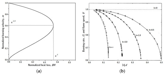
Figure 1.
(a) The dependence of the normalized burning velocity on the normalized radiative heat loss of a one-dimensional planar flame [1]; (b) burning rate, solid line, and normalized flame propagation speed , dash-dotted line, plotted against the ratio of flame thickness to channel width, d, for selected values of reduced heat transfer coefficient, k, within a quiescent, two-dimensional channel flow [35].
The size of a flame depends on how easily heat spreads (thermal diffusivity) and how fast the flame burns (flame speed), which, in turn, is influenced by the amount of fuel and its temperature. This means that the quenching diameter, in which the flame can no longer sustain itself, is determined by the fuel concentration and the properties of the fuel itself.
Figure 1b shows how the flame speed in a quiescent channel depends on its width (d) and the convective heat loss (k), which is proportional to the Nusselt number (), as mentioned previously. When the wall is adiabatic (), there is no heat loss from the flame to the wall, so the flame speed does not depend on channel width (). With increasing heat loss, the flame speed decreases until there is a critical channel width in which the flame can not propagate [35].
At a high level of convective heat transfer (), the flame extinguishes at , resulting in a quenching channel width of , or using the convention set in Table 2, , consistent with theory and experiments. Near-wall flame quenching occurs within 6% of the channel radius in a cold-wall scenario. Additionally [35], the flow velocity and direction also affect the quenching diameter; flames are more vulnerable to heat losses when the flow moves from the unburned to the burned side, and the quenching distance increases with higher flow rates. These findings match experimentally reported values [36].
4.2. Classification of Flame Types
Diffusion and premixed flames are two different kinds of micro combustion flames. In a premixed flame, combustion takes place after the fuel and oxidizer have been combined. The fuel and oxidizer in a diffusion flame are kept apart and only mixed as they move closer to the reaction zone [37].
The two subtypes of premixed flames are turbulent premixed flames and laminar premixed flames, as shown in Figure 2a,b. A laminar premixed flame is one in which the fuel and oxidizer mixture flows uniformly and without turbulence. In a turbulent premixed flame, on the other hand, the mixture of fuel and oxidizer is turbulent, meaning that it is characterized by random fluctuations in velocity and pressure [38].
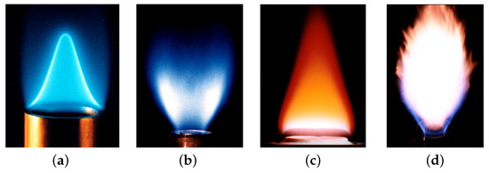
Figure 2.
Differences in premixed and diffusion flames: (a) Laminar premixed flame. (b) Turbulent premixed flame. (c) Laminar diffusion flame. (d) Turbulent diffusion flame [39].
Conversely, the separation of the fuel and oxidizer is what distinguishes a diffusion flame. When approaching the reaction zone, where combustion occurs, the fuel and oxidizer are only briefly mixed. Because of natural molecular diffusion, which is fueled by the concentration gradient of the two species, the fuel and oxidizer in a diffusion flame mix together [40]. Diffusion flames can also be classified into two types: laminar diffusion flames and turbulent diffusion flames, as shown in Figure 2c,d. The numerical studies of these type of diffusion flames at micro scales was studied by Resende et al. [11], where the authors extensively analyzed the importance of operating conditions, critical parameters, and the conjugate heat transfer/heat re-circulation.
Premixed and diffusion flames each have benefits and drawbacks. Premixed flames are commonly more efficient because they offer a more uniform mixture of fuel and oxidizer, which promotes faster combustion and less pollution. They may also have a smaller operating range and be more prone to explosions. While diffusion flames are typically more stable and capable of a wider range of operations, they may also be less effective and more polluting [37].
In the context of this review, we limited the analysis to premixed flames exclusively, and all mixtures were, as such, previously mixed. Therefore, it is imperative to note that, in the upcoming subsection, any discussion concerning the characteristics of micro-flames will pertain solely to premixed flames.
5. Classification of Micro-Flame Behaviours
The microflame is a complex phenomenon that can exhibit different behaviors, which are influenced by multiple factors, such as the input velocity of the fuel–oxidizer mixture, the heat flow rate supplied to the mixture, the thermal conduction coefficient of the burner walls (i.e., boundary conditions), and the burner geometry, among others. Thus, the present subsection aims to present a review of the possible behaviors of flames in microchannels, based on previous scientific research.
5.1. Flashback and Blow-Off
Premixed flames can experience situations where the reactant supply velocity exceeds or falls short of the flame speed, resulting in two possible scenarios for flame extinction [41,42], as observed in Figure 3:
- Flashback: This occurs when the velocity of the reactants supplied to the burner chamber is lower than the flame speed. As a result, the flame propagates upstream towards the fuel injection system, burning the reactants in a zone increasingly upstream, possibly self-extinguishing (Combustion instability-induced flashback is connected to the phenomenon of the instantaneous axial flow velocity experiencing significant reductions, sometimes even reaching negative values, during large-amplitude oscillations [43]).
- Blow-off: In this scenario, the reactants’ supply velocity is higher than the flame speed. The flame moves along the channel, burning the reactants in a zone increasingly downstream until it “blows off” (possibly self-extinguishing) when the fuel flow rate exceeds a certain limit.

Figure 3.
Flashback and blow-off for flames with fixed swirl: (a) flashback; (b) before flashback; (c) stable flame; (d) after blow-off [42].
Figure 3.
Flashback and blow-off for flames with fixed swirl: (a) flashback; (b) before flashback; (c) stable flame; (d) after blow-off [42].

The research paper by Fruzza et al. [44] studies the flashback of different H2/CH4 mixtures and uses 2D unsteady simulations with detailed kinetics and considers the fundamental role of the combustor wall by considering the Conjugate Heat Transfer. Different flashback regimes were studied for different H2 contents which highlights the significant difference between the critical flashback velocity and laminar flame speed at high H2 contents. This work was recently extended by Fruzza et al. [45], in which the authors coupled the numerical simulations with stochastic sensitivity analysis based on Generalized Polynomial Chaos, which allowed for the construction of a set of comprehensive maps for flashback velocities and burner temperatures for the parametric space of H2 content, equivalence ratio, and slit width.
Recently, Cai et al. [46] performed an experimental study on the the the flame dynamics of CH4-air within a micro-combustor with a flame holder and preheating channels. In addition to stable flame results, different types of blow-off dynamics were also presented, including anomalous blow-off dynamics at lower Reynolds numbers and fuel ultra-lean conditions, as observed in the stability maps presented in Figure 4B. It is found that, in these anomalous blow-off dynamics, the middle of the flame in the vertical direction presents a constricted shape, and that a flame with local extinction and reignition occurs periodically (see Figure 4C).
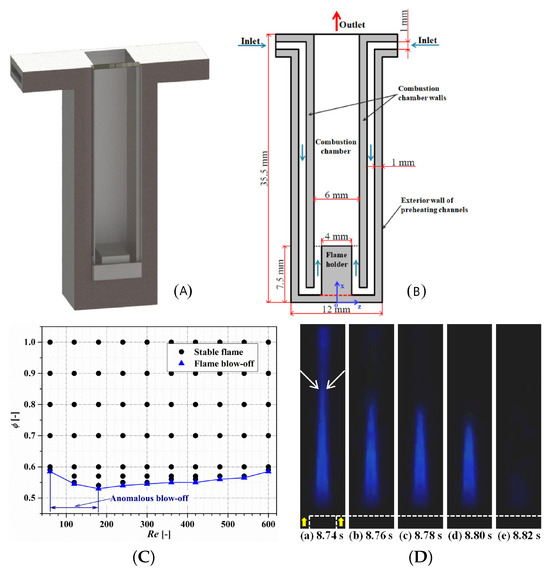
Figure 4.
Flame stability and blow-off dynamics for micro-combustion with a flame holder and preheating channels: (A) three-dimensional view of the burner; (B) cross-section drawn; (C) stability map; (D) blow-off dynamics [46].
5.2. Steady vs. Non-Steady Flames
Combustion can be classified as steady or non-steady/unsteady, which can be latter divided into periodic, quasi-periodic, and chaotic. Non-steady flames show fluctuations in their behavior, such as changes in their burning rate or flame shape that happen over time, in contrast to steady flames, which keep a consistent burning pace [47].
As illustrated in Figure 5, non-steady flames can exhibit different types of dynamics, including periodic, quasi-periodic, and chaotic behavior [48]:
- Periodic flames, which are characterized by fluctuations in their behavior that occur periodically over time, in a constant pattern, Figure 5a;
- Quasi-periodic flames, in which the oscillations present irregular periodicity and recurrence are observed, Figure 5b;
- Chaotic combustion, which can occur when steady combustion waves lose stability and transition to non-steady chaotic burning, exhibiting highly irregular and unpredictable behavior, Figure 5c.
The transition from steady to non-steady burning can be predicted using the nonlinear stability theory [47].

Figure 5.
Time-spectrum (up) and power series (down) for different non-steady combustion modes in ducted premixed flames: (a) periodic; (b) quasi-periodic; (c) haotic [49].
Figure 5.
Time-spectrum (up) and power series (down) for different non-steady combustion modes in ducted premixed flames: (a) periodic; (b) quasi-periodic; (c) haotic [49].

5.3. Mild Combustion
Mild combustion, also called flameless combustion, is a combustion mode that is distinguished by a relatively small temperature rise and an incomplete but considerable fuel conversion. It is generally observed at low inflow velocities and exhibits an axisymmetric shape. This mode has been identified in numerous research studies, and is typically characterized by the lack of a distinct temperature peak, as documented in [50]. It is a potentially beneficial flame type for applications requiring a weak heat source in microsystems.
On the other hand, the combustion process is contingent upon two critical factors [51,52]: the reactants must be preheated above the temperature at which they will self-ignite, and enough inert combustion products must be incorporated into the reaction area to saturate the flame. Furthermore, it is noteworthy to mention High Temperature Air Combustion, a technique that often leads to mild combustion scenarios, characterized by the synergistic utilization of highly preheated air and exhaust gas recirculation (EGR) in furnaces, resulting in high thermal efficiency and low NOx emissions [53,54].
The phenomenon of interest was first observed in micro-scale systems in Maruta et al. [55]. The authors conducted a comprehensive investigation into the combustion characteristics of such systems employing experimental, numerical, and analytical techniques. Specifically, a narrow cylindrical quartz channel with a fixed temperature gradient was utilized, possessing an inner diameter of . For sufficiently low velocities in the range of 2–3 [cm/s], it was observed that a sharp temperature gradient did not form between the chamber’s walls and the gas phase. The article by Pizza et al. [56] explored the combustion modes that occur in the three-dimensional combustion of premixed hydrogen and air in open cylindrical microtubes with the wall temperature controlled by gradually increasing it from the temperature of the incoming mixture to a final value of over the initial 1/20 length of the domain. This was achieved by applying a hyperbolic tangent function to smoothly ramp up the wall temperature. The researchers identified a particular type of mild combustion in both narrow and wider tubes with diameters of and , respectively, when using the lowest air inlet velocities, which were . The maximum temperature increase ranged from and (for of to , respectively).
The findings were consistent with the antecedent investigations conducted by the authors in their prior 2D study [57], wherein the phenomenon of mild combustion was also observed for low inlet velocities. The authors examined the dynamics of premixed hydrogen/air flames in a microchannel that is confined between two parallel, infinitely wide plates, and maintained a constant length-to-height aspect ratio of = 10 [−].
5.4. Stable Flames
Upon initiation of combustion, the flame undergoes movement either upstream or downstream before stabilizing at a particular location on the burner, as reported numerically by several studies [58,59] and experimentally observed in Maruta et al. [55]. This constitutes the simplest form of micro-flame behavior and is illustrated schematically in Figure 6.
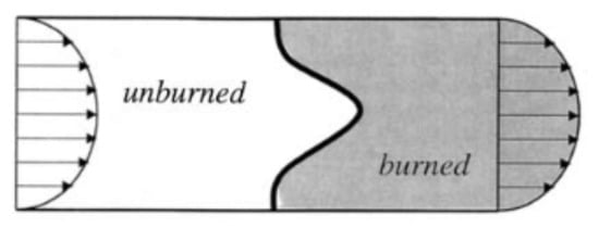
Figure 6.
Schematic representation of a stable micro-flame [35].
Typically, flames of this type exhibit a reduction in flame temperature as inlet velocity increases, which can impact heat transfer to the wall [60]. Additionally, distinct velocity profiles can influence flame propagation and structure [61]. As seen in Norton et al. [62], an increase in inlet velocity necessitates a greater distance for incoming gases to preheat, leading to downstream stabilization of the flame. This stabilization results in higher wall temperatures at the flame location and lower heat losses, ultimately leading to increased reaction rates and elevated flame temperatures, exceeding the adiabatic flame temperature [60].
This phenomenon, which can exhibit symmetric and asymmetric characteristics (or both, depending on the axis, if in 3D settings), has been observed both numerically, as in the work of Lamione et al. [63], experimentally, and analytically in multiple studies such as Lewis and Von Elbe [34], Kurdyumov et al. [64,65], Dogwiller et al. [66], and Tsai [67]. The previously mentioned articles by Pizza et al. [56,57] and the experimental observations by Maruta et al. [50,55] also corroborate these findings since the phenomenon was also identified in these studies.
Cai et al. [46] obtained stable flame dynamics of CH4–air within a micro-combustor with a flame holder and preheating channels for non fuel ultra-lean conditions. The flame stability map is quite high, showing the importance of preheating the incoming unburned mixture. The results demonstrate that, in cases with a stable flame, the increasing Reynolds and equivalence ratios pushed the flame downstream, leading to a significant increase in the flame heigh, presenting a remarkable anchored effect of the flow recirculation, as observed Figure 7.
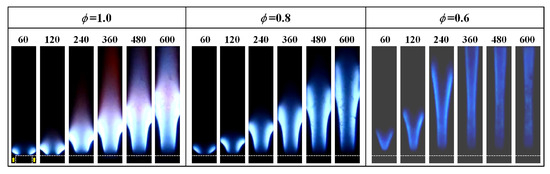
Figure 7.
Stable flame dynamics of CH4–air within a micro-combustor with a flame holder for different Reynolds numbers and equivalence ratios [46].
5.5. FREI: Flames with Repetitive Extinction and Ignition
Flames with repetitive extinction and ignition (FREI) refer to a specific type of flame behavior characterized by the repeated extinguishing and reignition of the flame, and this phenomenon is observed in various systems, including micro flow reactors and lean premixed hydrogen–air combustion [1,68,69].
In the region characterized by the FREI phenomenon, a distinctive behavior of the flame is apparent: it ignites in a downstream region, propagates towards the unburned gases, and eventually extinguishes in an upstream region. Over the course of simulation, it becomes evident that the flame consistently occupies the same region, with the phenomenon recurring cyclically. Following ignition, the flame is transported through these vortices to an upstream position, ultimately leading to its cessation.
Maruta et al. [55] first captured experimentally FREI flames in a straight micro-channel. These flames exhibit cyclic behavior with luminescence starting at ignition, moving upstream to extinction, and then reigniting after a delay. This cyclic process, illustrated in Figure 8a contrasts with the stable flame behavior shown in Figure 8b. Furthermore, other experimental investigations established that the dynamics of FREI also manifest in curved mesoscale channels [70] and later in mesoscale cylindrical combustors featuring a backward-facing step [71].
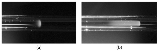
Figure 8.
Direct photographs of [55]: (a) stable flame; (b) FREI.
Numerous advancements in the computational field have been achieved by probing this phenomenon and utilizing lean hydrogen/air premixed flames, allowing for a better understanding of the FREI phenomena. Minaev et al. [72] provided a theoretical interpretation of FREI. They analyzed the non-stationary behavior of near-limit premixed flames in a microchannel with a temperature gradient. Their theoretical work resulted in a 1D nonlinear evolutionary equation for the flame front, explaining the flame stabilization, nonlinear oscillations, and repetitive extinction–ignition phenomena observed in the experiments. Later, Jackson et al. [73] numerically investigated FREI dynamics in a thermally active semi-infinite channel. They found stable solutions at specific flow rates, and instability leading to oscillations or extinction–reignition flames at higher flow rates, in alignment with experimental observations. The studies by Pizza et al., as mentioned earlier, observed FREI dynamics in planar micro combustors with prescribed wall temperatures at various channel heights [57] and also in 3D cylindrical microtubes [56]. Miyata et al. [74] performed direct numerical simulation to investigate FREI characteristics in a narrow circular channel, where they varied the wall temperature gradient and the inflow temperature in their study.
In a subsequent study, Alipoor and Mazaheri [68] scrutinized the FREI phenomenon through a singular simulation, affording a more intricate analysis of alternating extinction and ignition. In pursuit of this, contour maps of hydroxide radical (OH) concentrations were examined along the channel for various time instances, as shown in Figure 9. Furthermore, an investigation into heat release rate profiles, fluid and wall temperatures, the and molar concentrations of pertinent species central to the reaction was undertaken. Subsequently, flame bifurcation was evaluated from a hydrodynamic standpoint utilizing flow velocity vectors.
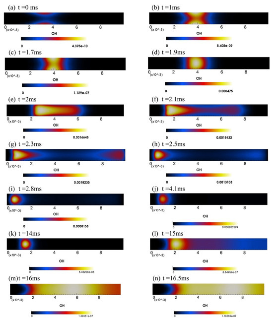
Figure 9.
Repetitive extinction-ignition dynamics using hydroxide mass fraction () [68].
Subsequently, the same authors [75] delved into flames featuring equivalence ratios ranging from 0.5 up to the stoichiometric condition of , in microchannels with widths spanning 0.4 to 1 mm. The accrued findings illustrated that augmentations to the equivalence ratio and burner width increased the amplitude of the FREI phenomenon while reducing its frequency. Furthermore, this examination illuminated that the phenomenon engenders fluid recirculation zones and flame bifurcation due to the presence of heavier species. These species exhibit an elevated heat absorption capacity, thereby inducing a temperature reduction.
Later, Alipoor and Mazaheri [76] conducted a comprehensive study concerning these flames within a heated microchannel possessing a hyperbolic temperature profile. Within this inquiry, three distinct flame behaviors were observed, including the FREI phenomenon. This phenomenon manifested under low velocities near the lower flammability limit. In pursuit of a deeper comprehension of the phenomenon’s causality, diverse simulations were performed, manipulating three key parameters: inlet velocity, equivalence ratio, and microchannel width. Elevating the velocity led to an escalated reaction intensity, consequently inducing rapid flame front extinction. Increasing the equivalence ratio from 0.5 to 0.6 resulted in an enhanced flame speed due to the augmented burning rate of the flame front, thus validating its accelerated extinction.
Beyond utilizing hydrogen as a fuel, the prospect of employing alternative fuels in microcombustion studies is viable. The FREI phenomenon was also observed in the research conducted by Biswas [77]. In this instance, a CH4/air mixture was employed, with ignition achieved through inserting a spark into the burner. The combustion of this mixture under stoichiometric conditions was examined within both a linear microchannel and a microchannel characterized by a contraction (convergent–divergent).
Additionally, other computational investigations have been conducted to enhance our comprehension of the FREI phenomenon across diverse fuel types. Nakamura et al. [78], Tsuboi et al. [79], and Miyata et al. [74] undertook analyses involving CH4 and air mixtures. Initially, they employed a one-dimensional model, subsequently validated against their experimental findings. Subsequently, they exclusively utilized direct numerical simulations to scrutinize the impact of boundary conditions—such as inlet temperature and wall temperature gradient—on the flame dynamics. The combustion characteristics of n-heptane–air were subject to experimental and numerical inquiry by Yamamoto et al. [80], wherein they also noted the manifestation of FREI dynamics.
5.6. PFB: Pulsatory Flame Burst
The phenomenon known as Pulsatory Flame Burst (PFB) is a specific flame behavior characterized by burst-like flame pulsation due to flow and combustion interactions. Currently, PFB only occurs in undulating geometries with premixed hydrogen and air, and the flame bursts involve the ignition, propagation, bifurcation (splitting), and extinction of the flame in a cyclic manner. Unlike FREI, where the flame extinguishes upstream, in PFB, a new flame emerges before the current one extinguishes. This prevents complete extinction, marking a significant difference.
PFB, though initially observed without distinction from FREI, was first identified in the course of micropropulsion studies conducted with wavy geometries [81,82], involving various inlet velocities and equivalence ratios, using a mixture of H2 and air. The geometry used is similar to our research, and it incorporated different wall conditions (hyperbolic and linear temperature profiles, as well as adiabatic conditions). Under the linear profile and adiabatic conditions, some simulations exhibited the phenomenon of PFB. This suggests that the microchannel geometry recirculates combustion energy, preventing flame extinction by flame lifting at higher speeds. Regarding propulsion capacity, it was found that increasing both the inlet velocity and equivalence ratio contribute to higher propulsion indicators. This underscores the significance of PFB, as pulsating flames exhibit substantial peaks in specific impulses.
Only in a subsequent study by Resende et al. [83], was PFB accurately identified and named. This investigation delved into stable and pulsatory flame burst behaviors within an undulating geometry, utilizing premixed hydrogen and air (with an equivalence ratio of ) and applying a linear temperature profile along the wall. The findings revealed that, at a lower inlet velocity (), the flame maintained stability, while at higher velocities, it exhibited pulsatory burst dynamics. The interplay between fluid dynamics and combustion response proved crucial, particularly due to vortices generated by the nonlinear burner geometry. With increased inlet velocity, the heat release rate transmitted through the vortices diminished, leading to ignition delay. This was evident through a reduced pulsatory burst frequency and a heightened peak heat release rate, albeit not substantial enough to amplify the maximum temperature amplitude. In Figure 10 and Figure 11 the results of a typical PFB flame are presented, as reported in [83].
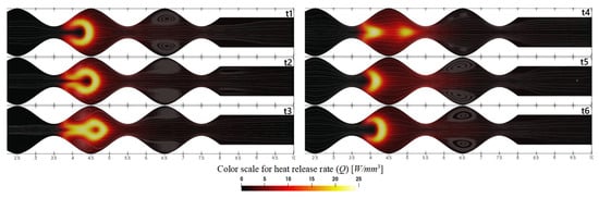
Figure 10.
Streamlines of the flow field and heat release rate distribution for the pulsatory flame burst dynamics with , with 10 ms intervals [83].
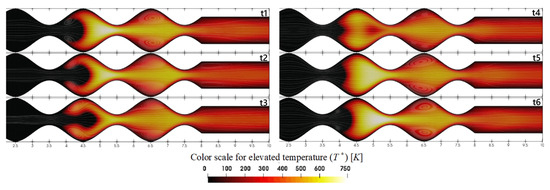
Figure 11.
Streamlines of the flow field and temperature distribution for the pulsatory flame burst dynamics with , with 10 ms intervals [83].
6. Numerical Investigations in Microcombustion
Li et al. [84] conducted numerical investigations into the combustion characteristics of hydrogen/air premixed flames in microtubes and parallel-plate microchannels with hydraulic diameters less than one millimeter. The results showed that microtubes lead to higher flame and wall temperatures, in comparison to parallel-plate microchannels. In subsequent studies, Li et al. [60] performed a similar investigation using methane as the fuel, finding higher temperatures in parallel-plate microchannels. Moreover, the upper flammability limit of the hydrogen/air mixture was higher than that of methane due to hydrogen’s faster burning rate.
The wall thickness of the burner, flame thickness, and hydraulic diameter are of the same order of magnitude in microcombustion chambers. Therefore, heat transfer through the wall and heat recirculation have a significant impact on combustion sustainability and its characteristics. Ronney [85] demonstrated that, for burners with counterflow zones and heat recirculation, heat conduction through the wall in the direction of flow has a crucial effect on flammability limits, particularly in flows with low Reynolds numbers.
To investigate the effect of heat recirculation on flammability limits, Kim et al. [86] experimentally studied the use of Swiss-roll microburners with channel widths smaller than the extinction diameter for propane/air combustion. Here it was found that a stable propane/air flame could be observed in channels with dimensions smaller than the quenching diameter for a wide range of inlet velocities and equivalence ratios, primarily due to heat recirculation. Kuo and Ronney [87] also numerically investigated heat recirculation in a Swiss-roll microburner and suggested that heat conduction along the burner wall, dividing the reactant flow from the reaction product flow, reduces the reaction temperature and extends extinction limits.
Recently, the use of catalyst-containing surfaces [88,89] has been studied for potential application in Swiss-roll burners. In Pizza et al. [90,91], it was found that instabilities in hydrogen/air premixed flames in parallel-plate burners could be avoided through the use of catalysts. Zhou et al. [92] experimentally and numerically tested three microburners with copper, alumina, and quartz catalysts, confirming the advantages of catalyst utilization in combustion.
Flow recirculation zones, as well as low-velocity zones achievable through combustion chamber design, are highly effective techniques for flame stabilization. One common technique involves the insertion of a backward-facing step in the burner walls. In this regard, Yang et al. [93] experimentally investigated the enhancement of a thermophotovoltaic microcombustion system’s efficiency using a backward-facing step in the combustion chamber. They concluded that the step insertion is useful for controlling the flame position and extending flammability limits. An experimental study on wall temperature and radiation heat flux from cylindrical microburners with a backward-facing step (as observed in Figure 12), conducted by Li et al. [94], revealed that optimal efficiency occurs at an equivalence ratio of 0.8, regardless of the burner’s dimensions and flow velocity. Furthermore, it was found that the backward-facing step is helpful in stabilizing flame positions. Khandelwal et al. [95] experimentally investigated flame stabilization in a microtube with three steps and found that flammability limits increase with the number of steps inserted in the reaction zone. Faramarzpour et al. [96] conducted a numerical study on the effects of microburner geometry and inlet velocity on flame position and radiation efficiency. The results showed that the presence of the backward-facing step stabilizes the flame at high velocities, increases the average outer wall temperature, and anchors the flame closer to the burner inlet.
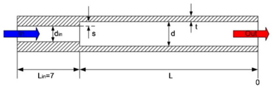
Figure 12.
Example of a backward-facing step insertion in a microcombustor, used in Li et al. [94].
Fan et al. [97] explored the impact of obstacles (bluff body) on hydrogen/air premixed flames. They investigated triangular and circular obstacles, concluding that the insertion of obstacles increases the combustion flammability limits. Yang et al. [98] studied hydrogen/air premixed flames in a convergent–divergent microtube, represented in Figure 13. They simplified the geometry to two dimensions and used experimental temperature distribution data on the outer surface of the microtube as the thermal boundary conditions in numerical simulations. Their findings showed stable combustion for equivalence ratios ranging from 0.6 to 2.2 and inlet velocities from 3.4 m/s to 41.4 m/s. Comparing these results with a regular microtube, they observed broader flammability limits in the convergent–divergent microtube. Later, Biwas et al. [99] numerically investigated the extinction and flame propagation behaviors of methane/air premixed flames in straight and convergent–divergent microchannels with diameters ranging from 1 to 10 mm. They examined the effects of microchannel diameter, equivalence ratio, inlet velocity, and exit-to-throat area ratio. Adiabatic wall conditions with conjugate heat transfer were considered. Their results indicated that flames extinguish more readily in convergent–divergent microchannels than in straight microchannels under adiabatic conditions.
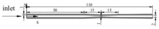
Figure 13.
Schematics of the microburner used in Yang et al. [98].
Rao et al. [100] presented a numerical work on a micro-combustor with a slotted bluff body, with a flame-tip opening, observing that the presence of the central bluff adversely affects the combustion characteristics, leading to reduced average combustion efficiency and exhaust gas temperature. In order to minimize this adverse effect, Rao et al. [100] introduced a deflector downstream of the bluff body, that significantly increased the temperature in the central region due to a secondary flame. Zhang et al. [101] used a similar deflector strategy to try to improve combustion stability, using a slotted blunt body with a front baffle instead of the downstream position. Zhang et al. [101] confirmed the synergistic effectiveness of a blunt body slot and front baffle, with the front baffle increasing the regulation of the fuel supply while decreasing the pressure loss in the micro combustor.
Abbaspour and Alipoor [102] conducted numerical investigations into hydrogen/air premixed flame characteristics and behaviors in heated convergent–divergent microtubes. Results showed that the convergent–divergent section led to decreased flame temperature due to increased flow velocity and convective heat transfer, resulting in oscillating flames. However, this geometry also contributed to flame stability. When the flame stabilized near the outlet section, reduced flame wall instability and increased upper flammability limits were observed due to enhanced heat recirculation in the convergent–divergent section.
Zhao et al. [103] used a heat-recirculating approach to perform an in-depth investigation into the thermal performance, entropy generation, and pollutant emissions of a micro-combustor fuelled by blended H2 and ammonia to increase flammability in atmospheric micro-combustion, as observed in Figure 14. They show that the thermal performance of the micro-combustor depends significantly on the inlet velocity and inlet equivalence ratio, while the impact of blending ratio between the hydrogen and ammonia is relatively minimal.
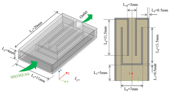
Figure 14.
Microcombustor with heat recirculating approach [103].
The use of flow recirculation zones is also interesting in some applications of micro-combustion within micro-thermophotovoltaic systems, as in the recent work of Li et al. [104] regarding the comparison between the performance of the traditional micro combustor and the a modified microcombustor with twisted tape inserted, as observed in Figure 15a. The results show that the inclusion of the twisted tape in the new micro-thermophotovoltaic systems reduces the radial thermal resistance and increases the gas residence time, when compared with the classical system. He et al. [105] presented other modification to the micro-thermophotovoltaic system using internal spiral fines, and showed that internal spiral fins can effectively improve the energy efficiency and energy output, but with high pressure loss. The optimal value for the ratio of the length of the fin and the outer diameter was suggested to be 5/2, while the optimal ratio between the internal spiral fin pitch distance and the outer diameter should be greater than 9.42/4. Cai et al. [3] presented a comprehensive review on the recent advances on stabilization of micro-thermophotovoltaic systems, exploring the thermal effects, pollutant emission, and energy conversion.
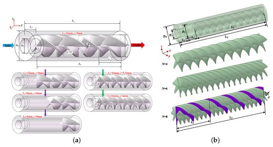
Figure 15.
Geometrical model of micro-thermophotovoltaic: (a) micro-combustor with twisted tape [104]; (b) micro-combustor with internal spiral fins [105].
In recent years, studies have explored microburners with nonlinear geometries. Wan et al. [106] numerically studied hydrogen/air mixture combustion in a microburner with wall cavities, as observed in Figure 16, varying cavity depth, and other reaction parameters. As the mixture velocity increased, the flame separated into two distinct zones, leading to significant fuel leakage from the reaction zone and a sharp decrease in the hydrogen conversion rate. They concluded that excessively deep cavities are detrimental when the burner is used as a heat source for thermoelectric or thermophotovoltaic devices, as flame separation results in more temperature peaks along the burner with lower intensities, reducing flame temperature. Yang et al. [107] conducted a similar study, focusing on burners with double cavities.
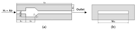
Figure 16.
Microcombustor with cavity schematic [106]: (a) longitudinal plane; (b) transverse plan.
Various studies have examined the flame dynamics in combustion chambers with diameters close to their extinction diameters. These studies often assume a negligible wall thickness in microburners, creating a significant difference in heat propagation rates between the fluid and walls. A constant temperature profile is typically used as the temperature boundary condition on the wall. Pizza et al. conducted numerous numerical studies on the dynamics of hydrogen/air premixed flames in heated meso channels [108], microchannels [57], and microtubes [56]. Different flame dynamics were observed, including FREI, mild combustion, swirling flames, and stable symmetrical flames. Later, Alipoor and Mazaheri [76] presented flame dynamics maps for hydrogen/air premixed flames based on three parameters: inlet velocity, equivalence ratio, and microchannel width, which are shown below in Figure 17.
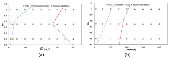
Figure 17.
Flame dynamics diagrams [76]. Effect of and for a channel width of: (a) 0.6 mm; (b) 0.8 mm.
Boyarko et al. [109] aimed to understand the physics and chemistry of combustion processes in microreactors for microspacecraft propulsion systems. These microspacecraft are designed to have a mass of less than 50 kg, with propulsion systems capable of delivering impulses of 1–10 mN. Micropropulsion systems exhibit distinct behaviors compared to larger-scale systems due to differences in flow rates and heat loss variations to the surroundings. The study analyzed flames in a microtube, chosen for its ease of being manufactured from catalytic materials and its simple geometry, suitable for simulations to validate the case under investigation. Experimentally, they explored the role of catalyst-coated tube surfaces in 0.4 mm and 0.8 mm diameter tubes, with a focus on rich hydrogen and oxygen mixtures.
Investigations in Wavy Wall Geometries
The literature on wavy wall geometries in microcombustion is notably limited. The initial research into this subject was led by Mansouri [110]. This study utilized numerical analysis to evaluate the impact of a newly devised micro-channel characterized by wavy walls on the performance of a micro-thermophotovoltaic system. This investigation proved crucial due to the substantial influence of burner geometry on the system’s power output. The study involved a two-dimensional numerical simulation using premixed CH4/air combustion, maintaining a constant velocity of and an equivalence ratio of across various wavy number configurations. The goal was to gain insights into flame behavior under varying kinetic mechanisms and wave-like designs.
Mansouri [111] later extended the study, examining how the equivalence ratio, inlet velocity, and burner height affect wavy burner geometry’s performance. The results showed an impressive 8.3% increase in conversion efficiency compared to flat burners, suggesting the adoption of undulating shapes in future micro-combustor designs and studies.
In their study, Han et al. [112] explored the impact of energy conversion improvement and NOx emissions in the context of thermophotovoltaic applications using ammonia/hydrogen mixtures. Among three distinct wavy combustor designs, it was observed that NOx emissions decreased notably in the wave-shaped design with smooth arcs. Furthermore, this particular design exhibited superior temperature uniformity at velocities exceeding 12 m/s.
In a recent study by Resende et al. [82], flame dynamics within a wave-shaped combustor featuring substantial divergence and convergence variations were investigated. The study employed a hydrogen/air mixture and revealed a pronounced interaction between fluid dynamics and chemical reactions. Specifically, the vortices within the convex regions were identified as acting to resist heat loss flux. Later, the study was extended (Resende et al. [83]) to investigate stable and pulsatory flame burst phenomena in an undulating geometry using premixed hydrogen and air with . Notably, this work introduced a linear temperature profile along the wall, allowing for an analysis of flow dynamics without imposing fixed flame locations. Two flame configurations were observed (stable for the lowest inlet velocity and PFB). The study emphasized the importance of the interaction between fluid dynamics and combustion, especially due to vortices formed by the burner’s nonlinear geometry.
Recently, Abbaspour and Alipoor [113] extended the previous work on convergent–divergent microtubes [102] by using a cosine wave-shaped combustor, and the results indicate that wavy walls facilitate the keeping and propagation of self-sustaining flames within the micro combustion chamber.
7. A Review of Micropropulsion
In this Section, we present a brief review of micropropulsion. The theoretical knowledge presented in the works of [114,115,116] forms the basis for our discussion here.
7.1. Overview on Micropropulsion Systems
Propulsion can be defined as [117]: “The action or process of drive something forward or onward by or as if by means of a force that imparts motion”. In other words, the propulsion system is a mechanical system which turns different forms of energy into kinetic energy.
The limitations of using conventional propulsion systems to deliver small and precise impulses for small satellites have necessitated the development of specific propulsion systems tailored to micro-scale applications [118,119]. In comparison to conventional propulsion systems, micropropulsion systems (MPS) exhibit two main characteristics (though, notably, a propulsion system that solely possesses the first characteristic outlined bellow, is commonly referred to as a micropropulsion system):
- (i)
- They possess the capability to generate relatively minor thrust with magnitudes ranging up to and impulse values of μNs up to mNs;
- (ii)
- They display a relatively low volume and weight profile.
MPS based on the use of propellants have traditionally been classified according to the state of the propellant, namely gas, solid, or liquid. However, recent advances in the development of propellantless technologies, such as the Solar Sail, have prompted the need for additional classification schemes. Figure 18 provides a concise summary of the classification schemes utilized.
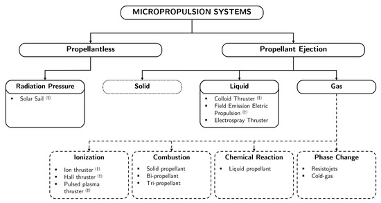
Figure 18.
Classification of micropropulsion concepts (based on [120]): the systems highlighted with (†) are manufactured with conventional methods whereas the ones without made using MEMS and silicon technologies.
As shown in Figure 18, another relevant categorization of MPS pertains to the manufacturing techniques employed, with some systems utilizing MEMS and silicon technologies (this research focuses specifically on such systems), while others utilize conventional methods.
7.2. Micropropulsion Systems Performance
MPS performance is commonly assessed under the framework of ideal rocket conditions. Nevertheless, it is crucial to acknowledge that these conditions rely on a set of assumptions that may not perfectly align with the realities of MPS. One such assumption is neglecting friction forces [116]. Hence, a cautious approach is required when applying these idealized models to micropropulsion scenarios. Therefore, the set of equations presented here (the indices correspond to those depicted in Figure 19) serves to provide insights into the ideal performance of micropropulsion systems. When analyzing the performance of the thruster, two key parameters are of major interest: specific impulse and thrust. These equations offer valuable information regarding the performance characteristics of such micropropulsion systems.
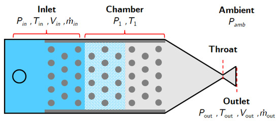
Figure 19.
Diagram of a MPS showing the variables and their indexes (adapted from [120]).
7.2.1. Thrust and Specific Impulse
In aircraft, thrust is normally explained through the application of Newton’s third law of action and reaction. A gas, or working fluid, is accelerated by the engine, and the reaction to this acceleration produces a force in the engine. The general derivation of the thrust equation shows that the amount of thrust generated depends on the mass flow rate through the engine and the gas exit velocity [121].
From Newton’s second law, force can be defined as the change in momentum of an object over time. Momentum is equal to the mass of the object times its velocity. When dealing with a gas, the thrust equation is given as:
where and are the mass flow rates at the outlet and inlet of the propulsion system, and are the respective average fluid velocities at the outlet and inlet of the propulsion system, and are the outlet and inlet pressures, and is the area of the outlet section.
In several cases, the outlet and inlet pressures of the propulsion system are equal to atmospheric pressure. In this case, the term becomes zero, and the equation can be simplified as:
It has been observed that the mass flow rate at the exit is equal to the sum of the mass flow rate at the inlet and the mass flow rate of fuel. By using the fuel-to-air equivalence ratio, , the following relation is obtained:
Let us introduce a new variable termed specific impulse , which serves as a measure of efficiency with respect to propellant consumption.
where the constant represents the gravitational acceleration on Earth at sea level. Despite being expressed in seconds, it does not indicate a measure of time; rather, it denotes the thrust per unit weight of propellant. For optimal propellant consumption efficiency, this value should be as high as possible.
Assuming constant velocity and pressure at the outlet and inlet, it becomes possible to simplify Equation (4). Through algebraic manipulations and by employing Equation (3), we arrive at Equation (5), wherein solely relies on the engine’s velocity difference.
The definition of this new variable brings several advantages to the analysis of propulsion systems. Firstly, the specific impulse is an indicator of the efficiency of the mechanism. Different engines will always have different values of specific impulse. An engine with a higher specific impulse will be more efficient since it produces more thrust for the same airflow. Secondly, as it is a specific property, the inlet mass flow rate can be omitted in all intermediate calculations, greatly simplifying the mathematical procedure. Thirdly, it is a variable that facilitates the design of the propulsion mechanism.
The incoming velocity is typically a known quantity, assuming that the profile is already fully developed and uniform across the inlet area. However, the exit velocity will vary across the outlet area. Therefore, it becomes necessary to calculate the average velocity (referred to as ) at the system’s exit. In mathematical terms, this value is defined as follows:
in other words, it is the integral of the magnitude of the velocity vector profile over the entire cross-sectional area at the outlet, divided by the cross-sectional outlet area.
7.2.2. Thrust Considering Chamber Pressure
One way to attain more precise impulse values is to simply not disregard the pressure differences between the combustion chamber and ambient pressure. Therefore, while the previous equations are simplified but valid, it is indispensable in the future to grasp the distinctions and advantages of using a more accurate and precise equation, such as [122]:
where is density, is the velocity component in an axial direction, u is a velocity vector, is the area of the fluid outlet, A is control surface, n is a unit vector normal to a plan is the pressure at the fluid outlet, and is the ambient pressure.
7.2.3. Thrust Key Indicators
In contemporary propulsion systems, multiple components such as turbines, compressors, and combustion chambers are commonly integrated. Typically, several compressors are employed in series to progressively increase the air pressure. Subsequently, the combustion chamber facilitates the reaction between fuel and air, followed by the installation of a turbine ahead of the propeller’s exit section. Propulsion is achieved through the difference between the inlet and outlet velocities, generating the desired thrust force.
Two highly relevant indicators in the realm of propulsion mechanisms emerge, although they are not addressed in this review. The first indicator is the Engine Pressure Ratio (EPR), defined as the ratio of the total pressure across the engine. As previously explained, modern engines consist of various components, and in this case, the EPR becomes the product of pressure ratios across all propulsion system components. Consequently, the EPR can be simplified and calculated as follows:
The second indicator is the Engine Temperature Ratio (ETR), which, analogously to the previous indicator, represents the ratio of the total temperature across various engine components. Similar to the previous case, given the complexity of modern engines, the ETR becomes the product of temperature ratios across the engine’s components. Hence, the ETR is calculated using the following expression:
7.3. Conventionally Manufactured Micropropulsion Systems
7.3.1. Pulsed Plasma Thruster
The PPT is an electromagnetic electric thruster that relies on a electromagnetic field to accelerate the plasma to produce thrust. It is based on the principle of the Lorentz force, which creates a force that accelerates the plasma to generate thrust. In other words, a high voltage discharge is generated between the cathode and the anode rod sleeve, which in turns heats the propellant (usually Teflon) making it decompose, which is then ionized to create a plasma. Specifically, the joint action of the magnetic pressure and the gas dynamic pressure in the thin layer of ionized gas accelerates the gas to produce thrust.
PPT operates in a pulsed manner due to the generation of sparks. As a result, continuous operation is not possible, hence the term “pulsed”. Figure 20a illustrates the working principle of the PPT, while Figure 20b showcases a working prototype developed by AIS [123].
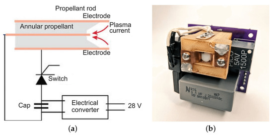
Figure 20.
Pulsed Plasma Thruster: (a) Working principle [124]; (b) prototype by AIS [123].
This system has garnered considerable interest among researchers owing to its straightforward design, cost-effectiveness, durability, and capacity for generating low-level outputs. Its track record of successful operation in space dates back to 1964 [125]. Recently, it has been used in CubeSat [126,127,128,129] and micro-satellite [130,131] missions successfully.
7.3.2. Field Emission Electric Propulsion
This type of devices uses a liquid propellant ejection system and must employ high-density substances to optimize thruster efficiency. As such, FEEP can be defined as an electrostatic electric propulsion system, that employs a high-voltage electrostatic field to accelerate charged ions for generating thrust. In Figure 21a the fundamental principles of a typical FEEP operation are illustrated, while in Figure 21b a working prototype developed by TU Dresden is presented [132].
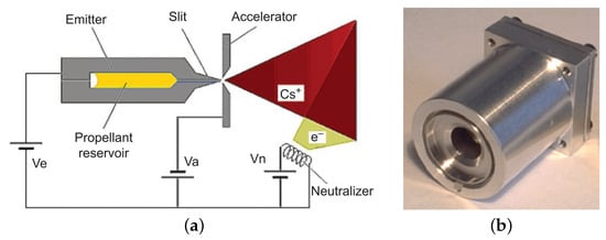
Figure 21.
Field emission eletric propulsion: (a) Working principle [133]; (b) prototype by TU Dresden [132].
FEEP consists of a transmitter with a propellant reservoir chamber, an accelerating electrode, and a neutralizer. It employs low-melting-point metals (e.g., cesium, indium) as propellants, stored as solids until liquefied by heating. Capillary action transports the liquid metal to the emitter outlet slit. With 8–15 kV applied between the emitter electrode and the accelerating electric field, metal ions overcome surface tension and gain acceleration, producing thrust [114]. Additionally, a positive voltage on the transmitter and a negative voltage on the accelerator create an electric field, enabling electron beams to discharge metal ions, minimizing pollution plume effects. Zhong et al. [134] studied the effect of the surface morphology of the emitting tip, using dynamic micro-electrochemical etching fabrication techniques to realize the micro-grooves processing of emitting tip surfaces at different depths by regulating roughening time and voltage frequency.
7.3.3. Other Relevant Micropropulsion System Technologies
Besides FEEP and PPT, there are other conventionally manufactured MPS options available, such as:
- Colloid Thruster: An electrostatic electric MPS similar to FEEP that uses high voltage and conductive liquids to accelerate charged particles, producing thrust. The thruster comprises charged particle emitters, extraction electrodes, an accelerating network, and a neutralizer to prevent ionic contamination on satellites. Different electrode potentials generate particle streams of varying polarities. The working principle of the colloid thruster [135] is represented in Figure 22a.
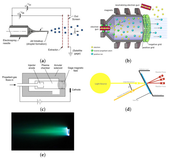 Figure 22. Working principle of: (a) colloid thruster [135]; (b) ion thruster [139]; (c) Hall thruster [135]; (d) Solar sail [144]; (e) discharge of the HMT thruster [140] using xenon.
 - Hall thruster and Ion Thruster: Devices that generate thrust by ejecting ions at high velocities. They can achieve high specific impulse, but typically produce low thrust levels. There are two main types: Hall thrusters and ion thrusters. Hall thrusters use the Hall effect to trap electrons, ionize the propellant, and then accelerate and exhaust it to create thrust. Ion thrusters, on the other hand, use charged grids to accelerate the ionized propellant [136,137,138]. This propulsion technology has already seen implementation in space missions and is capable of delivering thrust within the appropriate range for CubeSat missions. The working principle of the Ion thruster [139] and the Hall thruster [135] are represented in Figure 22b,c, respectively. Recently Dong et al. [140] proposed an advanced Watt class of Hall micro thrusters (HMT) for space gravitational wave detection. The research involved creating a circuit for thruster discharge and signal acquisition, using a Faraday probe to measure the plasma plume signal generated by the thruster. The discharge of the HMT thruster [140] using xenon is represented in Figure 22e.
- Solar sail: A spacecraft propulsion method that utilizes sunlight momentum to drive the craft forward [141]. It consists of a lightweight, reflective-coated sail with extreme thinness (down to 4.5 microns) and substantial size (hundreds of meters or kilometers) [142]. Photons from the Sun impart momentum to the sail, propelling the spacecraft and this continuous acceleration allows for high speeds over time. Solar sails have various advantages, including cost effectiveness, sustainability, applicability to small satellites, and the potential for long operating lifetimes [143]. This technology shows great promise for efficient and lightweight space travel. The working principle of the Solar sail [144] is represented in Figure 22).
- Laser Micropropulsion (LMP): The concept of laser propulsion was first introduced by Kantrowitz [145], presenting the advantages of being cost effective, with a high specific impulse, and an excellent thrust power ratio, and has gained significant recognition in the applications in micro/nano satellite propulsion. Nevertheless, the widespread adoption of LMP technology is limited by the proper selection of propellant. Recently, Rao et al. [146,147] presented an innovative LMP technology using metal-organic frameworks (MOFs) and also MOF-derived Carbon-encapsulated-Nano-Metal Composites (CNMC) as the propellant. The characteristic structure in CNMC overcomes the challenge of local hot zones caused by uneven physical mixing encountered in traditional LMP approaches. The ability to manipulate the metal content in MOFs allows for the optimization of laser propulsion performance, paving the way for further enhancements.
7.4. Micro-Electro-Mechanical Systems
The focus of this subsection is a comprehensive investigation of MEMS micropropulsion systems, specifically with regards to their suitability for implementation in nano- and picosatellites. As mentioned previously, the utilization of MEMS holds great potential for the development of highly compact spacecraft, owing to their ability to fabricate extremely small features and seamlessly integrate electronics [148]. More specifically, we delve into systems characterized by the incorporation of MEMS (Micro-Electro-Mechanical Systems) and silicon technologies specifically in the construction of the thruster component. It is noteworthy that some systems may incorporate MEMS elements, such as sensors, but these singular components do not categorically define the entire system as MEMS micropropulsion.
MEMS Manufacturing
Many of these systems operate within the micro to nanometer scales, and they fluidly combine mechanical and electrical components into a unified device. In the context of micropropulsion, the mechanical aspects encompass features like fluidic channels and structural components, while the electrical aspects involve components such as resistive heaters, sensors, and so on [149]. Nevertheless, defining precise boundaries between these mechanical and electrical components within MEMS can be challenging due to the intricate processes occurring within these devices.
The fabrication of these devices, as shown in Figure 23, typically encompasses a sequence of iterative procedures, commencing with a silicon wafer, and then involving these processes [120]:
- Deposition: This step entails the deposition of minute layers of materials onto the surface of the silicon wafer.
- Patterning: Patterning is employed to imprint a specific design onto the surface, thereby safeguarding certain regions while exposing others to shape the device’s features.
- Etching: Etching serves the purpose of material removal from the exposed areas, employing either isotropic or anisotropic techniques.

Figure 23.
Metal MEMS fabrication process [150].
Figure 23.
Metal MEMS fabrication process [150].

7.5. MEMS Categories
In summary, there are two major types of micropropulsion systems that utilize MEMS technology, with one of them further dividing into two subgroups. These are MEMS Electrical Thrusters (split into Electrothermal and Electrostatic) and MEMS Chemical Thrusters. Additionally, we have a system of microthrusters called Cold-gas, that are purely mechanical and do not use electrothermal, electrostatic, or chemical methods.
7.5.1. Electrothermal MEMS Electrical Thrusters
These systems operate through a dual process: first, by employing electrical resistance heaters to heat gas within the thrust chamber, and subsequently expelling the heated gas through a nozzle to generate thrust.
Resistojets are among the most prevalent electrothermal MEMS microthrusters. In contrast to certain early designs, like the one introduced by Bayt [151] (gas-fed Resistojets), which employed propellants in the gaseous phase, some of these systems now utilize propellants in liquid or solid states, resulting in phase changes as the gas undergoes heating.
Based on the specific phase-change characteristics exhibited by these devices, we can categorize them into two types of micro-resistojets, each associated with distinct flow regimes:
- Vaporizing Liquid Microthruster (VLM): They have been in development since the 1960s [152,153,154,155], and the design comprises an inlet channel for propellant feed, a chamber where a heating element vaporizes the propellant, and a convergent–divergent nozzle to propel the gases to supersonic speeds, as observed in Figure 24a). Several designs demonstrate significant potential, achieving a specific impulse () exceeding 100 s [156,157,158];
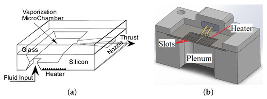 Figure 24. Working principle of: (a) VLM [166]; (b) LPM [120].
 - Low-Pressure Microresistojet (LPM, also referred to as the Free Molecule Micro-Resistojet): They operate in the transitional flow regime (0.1 < Kn ≤ 10) [120]. To model and simulate its operation, statistical methods based on gas kinetic theory are required [159,160]. These devices typically consist of an inlet section, a low-pressure plenum (typically below 1000 Pa), and a MEMS-manufactured heater chip with channels to accelerate the gas, as observed in Figure 24b). The design of these channels is critical for efficient heat transfer and overall thruster efficiency [161,162]. The choice of resistance type and manufacturing approach is also essential for the optimal conversion of electrical to thermal energy. Current designs show of around 7∼39 s [163,164,165].
Other electrothermal designs are the Solid Sublimation Microthruster, which operate by sublimating a solid propellant, which means they use electrical energy to heat the solid propellant, causing it to go directly from a solid to a gaseous state, with of around 50∼75 [167].
7.5.2. Electrostatic MEMS Electrical Thrusters
Electrostatic MEMS electrical thrusters function on two separate principles: field-effect ion engines (FET ion engines) and colloid thrusters. They operate similarly, with the primary distinction lying in the choice of propellant. While FET ion engines employ low melting point metallic propellants (such as cesium or indium), colloid thrusters utilize ionic liquids or mixtures [167].
In FET ion engines, multiple electrode layers on a silicon substrate create a strong electric field, ionizing liquid metal and expelling positively charged metal atoms for thrust. Electrons are discharged externally. This design offers low power consumption, high specific impulse (up to thousands of seconds), and precise low thrust control.
MEMS microcolloid thrusters operate similarly to field effect particle thrusters but use nonmetallic liquid propellants to accelerate tiny charged droplets. They have a higher operating voltage and thrust density than field effect ion engines but a lower specific impulse compared to electrothermal thrusters (schematic in Figure 25).
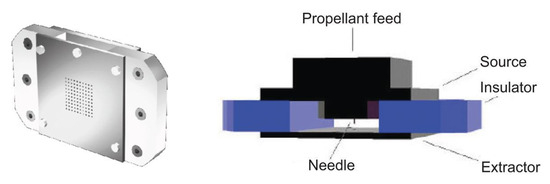
Figure 25.
Schematic of advanced microcolloid thruster by Stanford University [168].
A specific type of these systems is the Electrospray thrusters, which operate by emitting a particle spray through a Taylor cone effect, which is triggered by applying an electric potential to an ionic liquid in a capillary. This cone sharpens and releases particles, including single ions or droplets, when a threshold voltage is reached. Propellant options include ionic liquids, mixtures, or liquid metals, and an accelerator grid can be added after the extractor to boost particle exit velocity [169,170]. See Figure 26 for a schematic.

Figure 26.
Schematic of an electrospray thruster [120].
7.5.3. MEMS Chemical Thrusters
MEMS microchemical thrusters can employ either solid or liquid propellants, such as double-base solid nitrocellulose. While they offer higher thrust compared to electrothermal thrusters, their performance lags behind that of electrostatic and electromagnetic thrusters. The typical for MEMS microchemical thrusters falls in the range of 100 to 300 s. A common example of a MEMS microchemical thruster is a digital microarray. Utilizing MEMS (Micro-Electro-Mechanical Systems) technology and SOC (System-on-a-Chip) technology, these thrusters consolidate various components into a single chip. This integration includes the address driving circuit, ignition system, working fluid reservoir, combustion chamber, valves, and microminiature nozzles. A shematics of the working principle of both solid and liquid propellant microthrusters is presented in Figure 27.
Solid propellant microthrusters [171,172,173,174,175] comprise a chamber housing a limited propellant quantity, an igniter, often in the form of a heater, and a nozzle for gas acceleration following combustion. These systems are exceptionally compact because they do not require a feeding system or a pressurized container. Recently, Lee et al. [176,177] presented a new PCB micro-ignitor concept without using membranes, using a process based on the lab-on-PCB technique and stencil printing. This PCB micro-ignitor integrates an AP/PDMS solid propellant and stencil-printed heaters. Additionally, Lee et al. [176,177] presented a parametric study to obtain the proper heater dimensions that ensure consistent heat transfer between the heater and the solid propellant. Kan et al. [178] proposed a safety control function for the micro-igniter aiming at improve the output energy. In order to minimize the misaction caused by traditional micro-igniters due to false triggering, Kan et al. [178] proposed a MEMS safety device based on Lorentz force. Kan et al. [179] performed an experimental study of the effect of carbon nanomaterials (CNMs) on the ignition and thrust performance of various types of oxygenated salts/nanothermite mixtures. The authors used CNMs that included graphene–oxide (GO), reduced GO, and carbon nanotubes (CNTs), and demonstrated that non-metallic oxidizers is a good alternative energetic oxidants for thermite mixtures with high combustion performance. The CNMs used by Kan et al. [179] used a simple ultrasonic mixing method to integrate the CNMs into nanothermite compositions.
Liquid propellants microthrusters, using components such as hydrazine and hydrogen peroxide, decompose the propellants into hot gases when catalyzed, which are then accelerated through a nozzle to generate thrust. While hydrazine is a common choice for its medium-level performance, it poses safety challenges due to toxicity and flammability [180]. In contrast, hydrogen peroxide is a safer alternative but can slowly decompose when in contact with organic materials [181,182]. This decomposition risk may lead to propellant loss in CubeSats stored for extended periods before launch.

Figure 27.
Working principle of: (a) Liquid Propellant Microthruster [122]; (b) Solid Propellant Microthruster [183].
Figure 27.
Working principle of: (a) Liquid Propellant Microthruster [122]; (b) Solid Propellant Microthruster [183].

This review focuses on microcombustion in the field of micropropulsion, a critical component of nanosatellite propulsion systems. Chen et al. [184] developed a hydrogen-based micropropulsion system using catalytic microcombustion to provide power for microsatellites’ maneuvers. They experimentally and numerically studied this system’s performance, investigating parameters like fuel/air mixture flow rate, equivalence ratio, and nozzle contraction ratio. They used a platinum catalyst-coated tube with a 500 µm diameter and 1 cm length as the reactor, inserted into a quartz tube with various converging-diverging nozzle ratios. It explored different flame behaviors and intrinsic properties, including the temperature and mass concentration of key species (H2, OH, H2O).
7.5.4. Cold-Gas Microthrusters
This micropropulsion system employs pressurized gas as propellant, which can be stored in various phases (liquid, gaseous, or solid). They are a type of microthruster that operates based on a simple mechanical principle without the use of electrothermal, electrostatic, or chemical methods. The gas is accelerated through a nozzle to generate thrust, as observed in Figure 28. One challenge is managing leakage, as microscopic particle contamination can affect valve sealing and lead to propellant loss. These systems are well-developed for CubeSats due to their simplicity [120]. Some models even feature integrated control circuits for satellite interfacing [120]. Future advancements may include integrated sensors and control valves. Propellant can be stored as gas, liquid, or solid, with efficient ignition being crucial, and inert gases are commonly used for safety reasons, though using low-boiling-point liquids like butane may improve efficiency [120].
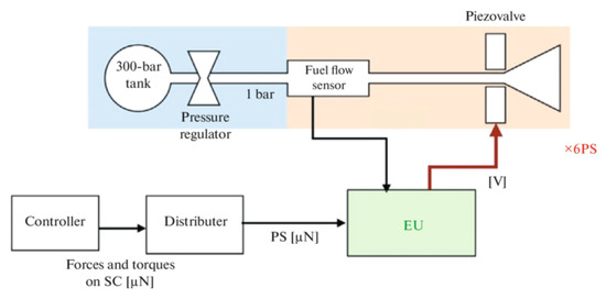
Figure 28.
Functional diagram of the circuit of a cold-gas microthruster [185].
8. Conclusions
This work presented a review intended to provide insights into micro-combustion and micro propulsion. Starting with the explorations of the different challenges of micro-combustion and the typical length and time scales involved in micro-combustion. Next we presented a review for the types of micro-flame dynamics, and in the final part of this review, we focused on micro-propulsion systems, their performance metrics, conventional manufacturing methods, and the advancements in Micro-Electro-Mechanical Systems manufacturing. This review is an invaluable resource for researchers and engineers navigating the complexities of micro-scale combustion and propulsion.
Funding
A. M. Afonso acknowledge FCT—Fundação para a Ciência e a Tecnologia for financial support through LA/P/0045/2020 (ALiCE), UIDB/00532/2020 and UIDP/00532/2020 (CEFT), funded by national funds through FCT/MCTES (PIDDAC). P. R. Resende acknowledges the funding by FAPESP through Project No. 2015/26842-3.
Conflicts of Interest
The authors declare no conflicts of interest.
References
- Ju, Y.; Maruta, K. Microscale combustion: Technology development and fundamental research. Prog. Energy Combust. Sci. 2011, 37, 669–715. [Google Scholar] [CrossRef]
- Nakamura, Y.; Gao, J.; Matsuoka, T. Progress in small-scale combustion. J. Therm. Sci. Technol. 2017, 12, JTST0001. [Google Scholar] [CrossRef][Green Version]
- Cai, L.; Jiaqiang, E.; Li, J.; Ding, J.; Luo, B. A comprehensive review on combustion stabilization technologies of micro/meso-scale combustors for micro thermophotovoltaic systems: Thermal, emission, and energy conversion. Fuel 2023, 335, 126660. [Google Scholar] [CrossRef]
- Jabar, D.; Al-Fahham, M. A review of combustion parameters affecting length and flame structure. AIP Conf. Proc. 2024, 3051, 020001. [Google Scholar]
- Nauman, M.; Pan, J.; Wang, Y.; Li, F.; Ojo, A.O.; Raza, A. A review of recent advancements in micro combustion techniques to enhance flame stability and fuel residence time. Int. J. Hydrogen Energy 2023, 49, 1165–1193. [Google Scholar] [CrossRef]
- Merriam-Webster. Combustion. Available online: https://www.merriam-webster.com/dictionary/combustion (accessed on 28 March 2023).
- Fernandez-Pello, A.C. Micropower generation using combustion: Issues and approaches. Proc. Combust. Inst. 2002, 29, 883–899. [Google Scholar] [CrossRef]
- Thomas, G.; Oakley, G.; Bambrey, R. Fundamental studies of explosion arrester mitigation mechanisms. Process. Saf. Environ. Prot. 2020, 137, 15–33. [Google Scholar] [CrossRef]
- Davy, H., VII. Some researches on flame. Philos. Trans. R. Soc. Lond. 1817, 107, 45–76. [Google Scholar]
- Hossain, A.; Nakamura, Y. Thermal and chemical structures formed in the micro burner of miniaturized hydrogen-air jet flames. Proc. Combust. Inst. 2015, 35, 3413–3420. [Google Scholar] [CrossRef]
- Resende, P.R.; Ayoobi, M.; Afonso, A.M. Numerical investigations of micro-scale diffusion combustion: A brief review. Appl. Sci. 2019, 9, 3356. [Google Scholar] [CrossRef]
- Lee, L.N.; Kim, M.J.; Hwang, W.J. Potential of augmented reality and virtual reality technologies to promote wellbeing in older adults. Appl. Sci. 2019, 9, 3556. [Google Scholar] [CrossRef]
- Glassman, I.; Yetter, R. Flame phenomena in premixed combustible gases. In Combustion, 4th ed.; Academic Press: Cambridge, MA, USA, 2008; pp. 153–162. [Google Scholar]
- Li, Q.; Wang, J.; Meng, L.; Li, J.; Guo, Z. CFD study on stability limits of hydrogen/air premixed flames in planar micro-combustors with catalytic walls. Appl. Therm. Eng. 2017, 121, 325–335. [Google Scholar] [CrossRef]
- Kang, Z.; Shi, Z.; Ye, J.; Tian, X.; Huang, Z.; Wang, H.; Wei, D.; Peng, Q.; Tu, Y. A Review of Micro Power System and Micro Combustion: Present Situation, Techniques and Prospects. Energies 2023, 16, 3201. [Google Scholar] [CrossRef]
- Yun, T.M.; Kottke, P.A.; Anderson, D.M.; Fedorov, A.G. Experimental investigation of hydrogen production by variable volume membrane batch reactors with modulated liquid fuel introduction. Int. J. Hydrogen Energy 2015, 40, 2601–2612. [Google Scholar] [CrossRef]
- Wang, Y. Introduction to Micro-Scale Combustion: University Lecture at Pennsylvania State University. Available online: https://yang.gatech.edu/projects/Meso%20and%20Micro%20Scale%20Propulsion...(Yanxing)/files/micro-combustion%20(for%20webpage%20).pdf (accessed on 19 May 2023).
- Lee, M.J.; Cho, S.M.; Choi, B.I.; Kim, N.I. Scale and material effects on flame characteristics in small heat recirculation combustors of a counter-current channel type. Appl. Therm. Eng. 2010, 30, 2227–2235. [Google Scholar] [CrossRef]
- Tu, Y.; Liu, H.; Yang, W. Flame characteristics of CH4/H2 on a jet-in-hot-coflow burner diluted by N2, CO2, and H2O. Energy Fuels 2017, 31, 3270–3280. [Google Scholar] [CrossRef]
- Mohan, S.; Matalon, M. Diffusion flames and diffusion flame-streets in three dimensional micro-channels. Combust. Flame 2017, 177, 155–170. [Google Scholar] [CrossRef]
- Feldmeier, S.; Schwarz, M.; Wopienka, E.; Pfeifer, C. Categorization of small-scale biomass combustion appliances by characteristic numbers. Renew. Energy 2021, 163, 2128–2136. [Google Scholar] [CrossRef]
- Li, Y.H.; Chen, G.B.; Cheng, T.S.; Yeh, Y.L.; Chao, Y.C. Combustion characteristics of a small-scale combustor with a percolated platinum emitter tube for thermophotovoltaics. Energy 2013, 61, 150–157. [Google Scholar] [CrossRef]
- Kaisare, N.S.; Deshmukh, S.R.; Vlachos, D.G. Stability and performance of catalytic microreactors: Simulations of propane catalytic combustion on Pt. Chem. Eng. Sci. 2008, 63, 1098–1116. [Google Scholar] [CrossRef]
- Bagheri, G.; Hosseini, S.E.; Wahid, M.A. Effects of bluff body shape on the flame stability in premixed micro-combustion of hydrogen–air mixture. Appl. Therm. Eng. 2014, 67, 266–272. [Google Scholar] [CrossRef]
- Akhtar, S.; Khan, M.N.; Kurnia, J.C.; Shamim, T. Investigation of energy conversion and flame stability in a curved micro-combustor for thermo-photovoltaic (TPV) applications. Appl. Energy 2017, 192, 134–145. [Google Scholar] [CrossRef]
- Cao, Z.; Lyu, Y.; Peng, J.; Qiu, P.; Liu, L.; Yang, C.; Yu, Y.; Chang, G.; Yan, B.; Sun, S.; et al. Experimental study of flame evolution, frequency and oscillation characteristics of steam diluted micro-mixing hydrogen flame. Fuel 2021, 301, 121078. [Google Scholar] [CrossRef]
- Aggarwal, S.K. Extinction of laminar partially premixed flames. Prog. Energy Combust. Sci. 2009, 35, 528–570. [Google Scholar] [CrossRef]
- Fu, K.; Knobloch, A.J.; Martinez, F.C.; Walther, D.C.; Fernandez-Pello, C.; Pisano, A.P.; Liepmann, D.; Miyaska, K.; Maruta, K. Design and experimental results of small-scale rotary engines. In Proceedings of the ASME International Mechanical Engineering Congress and Exposition. American Society of Mechanical Engineers, New York, NY, USA, 11–16 November 2001; Volume 35524, pp. 295–301. [Google Scholar]
- Shanbhogue, S.; Sanusi, Y.; Taamallah, S.; Habib, M.; Mokheimer, E.; Ghoniem, A. Flame macrostructures, combustion instability and extinction strain scaling in swirl-stabilized premixed CH4/H2 combustion. Combust. Flame 2016, 163, 494–507. [Google Scholar] [CrossRef]
- Eckart, S.; Yu, C.; Maas, U.; Krause, H. Experimental and numerical investigations on extinction strain rates in non-premixed counterflow methane and propane flames in an oxygen reduced environment. Fuel 2021, 298, 120781. [Google Scholar] [CrossRef]
- Spalding, D.B. A theory of inflammability limits and flame-quenching. Proc. R. Soc. Lond. Ser. A Math. Phys. Sci. 1957, 240, 83–100. [Google Scholar]
- Maruta, K.; Yoshida, M.; Ju, Y.; Niioka, T. Experimental study on methane-air premixed flame extinction at small stretch rates in microgravity. In Proceedings of the Symposium (International) on Combustion, Napoli, Italy, 28 July 1996–2 August 1996; Elsevier: Amsterdam, The Netherlands, 1996; Volume 26-1, pp. 1283–1289. [Google Scholar]
- Ju, Y.; Maruta, K.; Niioka, T. Combustion Limits. Appl. Mech. Rev. 2001, 54, 257–277. [Google Scholar] [CrossRef]
- Lewis, B.; Von Elbe, G. Combustion, Flames and Explosions of Gases; Elsevier: Amsterdam, The Netherlands, 2012. [Google Scholar]
- Daou, J.; Matalon, M. Influence of conductive heat-losses on the propagation of premixed flames in channels. Combust. Flame 2002, 128, 321–339. [Google Scholar] [CrossRef]
- Ferguson, C.R.; Keck, J.C. On laminar flame quenching and its application to spark ignition engines. Combust. Flame 1977, 28, 197–205. [Google Scholar] [CrossRef]
- Law, C.K. Combustion Physics; Cambridge University Press: Cambridge, UK, 2010. [Google Scholar]
- Williams, F.A. Combustion Theory; Benjamin-Cummings Publishing Company: San Francisco, CA, USA, 1985. [Google Scholar]
- Bockhorn, H.; Habisreuther, P.; Hettel, M. Numerical Modelling of Technical Combustion: 100 Volumes of ‘Notes on Numerical Fluid Mechanics’: 40 Years of Numerical Fluid Mechanics and Aerodynamics in Retrospect; Springer: Berlin/Heidelberg, Germany, 2009; pp. 325–340. [Google Scholar] [CrossRef]
- Turns, S.R. Introduction to Combustion; McGraw-Hill Companies: New York, NY, USA, 1996; Volume 287. [Google Scholar]
- Lieuwen, T.C. Unsteady Combustor Physics; Cambridge University Press: Cambridge, UK, 2012. [Google Scholar] [CrossRef]
- Jerzak, W.; Kuźnia, M. Experimental study of impact of swirl number as well as oxygen and carbon dioxide content in natural gas combustion air on flame flashback and blow-off. J. Nat. Gas Sci. Eng. 2016, 29, 46–54. [Google Scholar] [CrossRef]
- Thibaut, D.; Candel, S. Numerical Study of Unsteady Turbulent Premixed Combustion: Application to Flashback Simulation. Combust. Flame 1998, 113, 53–65. [Google Scholar] [CrossRef]
- Fruzza, F.; Lamioni, R.; Tognotti, L.; Galletti, C. Flashback of H2-enriched premixed flames in perforated burners: Numerical prediction of critical velocity. Int. J. Hydrogen Energy 2023, 48, 31790–31801. [Google Scholar] [CrossRef]
- Fruzza, F.; Lamioni, R.; Mariotti, A.; Salvetti, M.V.; Galletti, C. Flashback propensity due to hydrogen blending in natural gas: Sensitivity to operating and geometrical parameters. Fuel 2024, 362, 130838. [Google Scholar] [CrossRef]
- Cai, S.; Yang, W.; Wan, J. Combustion and thermal performances of methane-air premixed flame in a novel preheated micro combustor with a flame holder. Int. J. Therm. Sci. 2024, 197, 108813. [Google Scholar] [CrossRef]
- Margolis, S.B. Chaotic Combustion of Solids and High-Density Fluids near Points of Strong Resonance. Proc. Math. Phys. Sci. 1991, 433, 131–150. [Google Scholar]
- Weng, Y.; Unni, V.R.; Sujith, R.; Saha, A. Synchronization framework for modeling transition to thermoacoustic instability in laminar combustors. Nonlinear Dyn. 2020, 100, 3295–3306. [Google Scholar] [CrossRef]
- Kabiraj, L.; Saurabh, A.; Wahi, P.; Sujith, R. Experimental study of thermoacoustic instability in ducted premixed flames: Periodic, quasi-periodic and chaotic oscillations. In Proceedings of the n3l-Int’l Summer School and Workshop on Non-Normal and Nonlinear Effects in Aero-and Thermoacoustics, Munich, Germany, 17–21 May 2010; p. 12. [Google Scholar]
- Maruta, K.; Muso, K.; Takeda, K.; Niioka, T. Reaction zone structure in flameless combustion. Proc. Combust. Inst. 2000, 28, 2117–2123. [Google Scholar] [CrossRef]
- Cavaliere, A.; De Joannon, M. Mild combustion. Prog. Energy Combust. Sci. 2004, 30, 329–366. [Google Scholar] [CrossRef]
- Wünning, J.; Wünning, J. Flameless oxidation to reduce thermal NO-formation. Prog. Energy Combust. Sci. 1997, 23, 81–94. [Google Scholar] [CrossRef]
- Katsuki, M.; Hasegawa, T. The science and technology of combustion in highly preheated air. Symp. Int. Combust. 1998, 27, 3135–3146. [Google Scholar] [CrossRef]
- Niioka, T. Fundamentals and applications of high-temperature air combustion. In Proceedings of the 5th ASME/JSME Thermal Engineering Joint Conference, San Diego, CA, USA, 15–19 March 1999; pp. 1–6. [Google Scholar]
- Maruta, K.; Kataoka, T.; Kim, N.I.; Minaev, S.; Fursenko, R. Characteristics of combustion in a narrow channel with a temperature gradient. Proc. Combust. Inst. 2005, 30, 2429–2436. [Google Scholar] [CrossRef]
- Pizza, G.; Frouzakis, C.E.; Mantzaras, J.; Tomboulides, A.G.; Boulouchos, K. Three-dimensional simulations of premixed hydrogen/air flames in microtubes. J. Fluid Mech. 2010, 658, 463–491. [Google Scholar] [CrossRef]
- Pizza, G.; Frouzakis, C.E.; Mantzaras, J.; Tomboulides, A.G.; Boulouchos, K. Dynamics of premixed hydrogen/air flames in microchannels. Combust. Flame 2008, 152, 433–450. [Google Scholar] [CrossRef]
- Tsuboi, Y.; Yokomori, T.; Maruta, K. Study on ignition and weak flame in heated meso-scale channel. In Proceedings of the ASME International Mechanical Engineering Congress and Exposition, Proceedings (IMECE), Seattle, WA, USA, 11–15 November 2007; pp. 155–158. [Google Scholar] [CrossRef]
- Di Stazio, A.; Chauveau, C.; Dayma, G.; Dagaut, P. Combustion in micro-channels with a controlled temperature gradient. Exp. Therm. Fluid Sci. 2016, 73, 79–86. [Google Scholar] [CrossRef]
- Li, J.; Chou, S.; Yang, W.; Li, Z. A numerical study on premixed micro-combustion of CH4–air mixture: Effects of combustor size, geometry and boundary conditions on flame temperature. Chem. Eng. J. 2009, 150, 213–222. [Google Scholar] [CrossRef]
- Kim, N.I.; Maruta, K. A numerical study on propagation of premixed flames in small tubes. Combust. Flame 2006, 146, 283–301. [Google Scholar] [CrossRef]
- Norton, D.G.; Vlachos, D.G. Combustion characteristics and flame stability at the microscale: A CFD study of premixed methane/air mixtures. Chem. Eng. Sci. 2003, 58, 4871–4882. [Google Scholar] [CrossRef]
- Lamioni, R.; Lapenna, P.E.; Berger, L.; Kleinheinz, K.; Attili, A.; Pitsch, H.; Creta, F. Pressure-induced hydrodynamic instability in premixed methane-air slot flames. Combust. Sci. Technol. 2020, 192, 1998–2009. [Google Scholar] [CrossRef]
- Kurdyumov, V.; Fernandez-Tarrazo, E. Lewis number effect on the propagation of premixed laminar flames in narrow open ducts. Combust. Flame 2002, 128, 382–394. [Google Scholar] [CrossRef]
- Kurdyumov, V.N.; Pizza, G.; Frouzakis, C.E.; Mantzaras, J. Dynamics of premixed flames in a narrow channel with a step-wise wall temperature. Combust. Flame 2009, 156, 2190–2200. [Google Scholar] [CrossRef]
- Dogwiler, U.; Mantzaras, J.; Benz, P.; Kaeppeli, B.; Bombach, R.; Arnold, A. Homogeneous ignition of methane-air mixtures over platinum: Comparison of measurements and detailed numerical predictions. In Proceedings of the Symposium (International) on Combustion, Boulder, CO, USA, 2–7 August 1998; Elsevier: Amsterdam, The Netherlands, 1998; Volume 27-2, pp. 2275–2282. [Google Scholar]
- Tsai, C.H. The asymmetric behavior of steady laminar flame propagation in ducts. Combust. Sci. Technol. 2008, 180, 533–545. [Google Scholar] [CrossRef]
- Alipoor, A.; Mazaheri, K. Studying the repetitive extinction-ignition dynamics for lean premixed hydrogen-air combustion in a heated microchannel. Energy 2014, 73, 367–379. [Google Scholar] [CrossRef]
- Lapointe, S.; Druzgalski, C.L.; McNenly, M.J. Numerical study of a micro flow reactor at engine pressures: Flames with repetitive extinction and ignition and simulations with a reduced chemical model. Combust. Flame 2018, 197, 102–110. [Google Scholar] [CrossRef]
- Richecoeur, F.; Kyritsis, D.C. Experimental study of flame stabilization in low Reynolds and Dean number flows in curved mesoscale ducts. Proc. Combust. Inst. 2005, 30, 2419–2427. [Google Scholar] [CrossRef]
- Baigmohammadi, M.; Tabejamaat, S.; Farsiani, Y. Experimental study of the effects of geometrical parameters, Reynolds number, and equivalence ratio on methane–oxygen premixed flame dynamics in non-adiabatic cylinderical meso-scale reactors with the backward facing step. Chem. Eng. Sci. 2015, 132, 215–233. [Google Scholar] [CrossRef]
- Minaev, S.; Maruta, K.; Fursenko, R. Nonlinear dynamics of flame in a narrow channel with a temperature gradient. Combust. Theory Model. 2007, 11, 187–203. [Google Scholar] [CrossRef]
- Jackson, T.; Buckmaster, J.; Lu, Z.; Kyritsis, D.; Massa, L. Flames in narrow circular tubes. Proc. Combust. Inst. 2007, 31, 955–962. [Google Scholar] [CrossRef]
- Miyata, E.; Fukushima, N.; Naka, Y.; Shimura, M.; Tanahashi, M.; Miyauchi, T. Direct numerical simulation of micro combustion in a narrow circular channel with a detailed kinetic mechanism. Proc. Combust. Inst. 2015, 35, 3421–3427. [Google Scholar] [CrossRef]
- Alipoor, A.; Mazaheri, K. Combustion characteristics and flame bifurcation in repetitive extinction-ignition dynamics for premixed hydrogen-air combustion in a heated micro channel. Energy 2016, 109, 650–663. [Google Scholar] [CrossRef]
- Alipoor, A.; Mazaheri, K. Maps of flame dynamics for premixed lean hydrogen-air combustion in a heated microchannel. Energy 2020, 194, 116852. [Google Scholar] [CrossRef]
- Biswas, S. Physics of Turbulent Jet Ignition: Mechanisms and Dynamics of Ultra-Lean Combustion; Springer: Berlin/Heidelberg, Germany, 2018. [Google Scholar]
- Nakamura, H.; Fan, A.; Minaev, S.; Sereshchenko, E.; Fursenko, R.; Tsuboi, Y.; Maruta, K. Bifurcations and negative propagation speeds of methane/air premixed flames with repetitive extinction and ignition in a heated microchannel. Combust. Flame 2012, 159, 1631–1643. [Google Scholar] [CrossRef]
- Tsuboi, Y.; Yokomori, T.; Maruta, K. Lower limit of weak flame in a heated channel. Proc. Combust. Inst. 2009, 32, 3075–3081. [Google Scholar] [CrossRef]
- Yamamoto, A.; Oshibe, H.; Nakamura, H.; Tezuka, T.; Hasegawa, S.; Maruta, K. Stabilized three-stage oxidation of gaseous n-heptane/air mixture in a micro flow reactor with a controlled temperature profile. Proc. Combust. Inst. 2011, 33, 3259–3266. [Google Scholar] [CrossRef]
- de Macedo, J.M.R.C. Estudos Numéricos em Micropropulsão. Master’s Thesis, Universidade do Porto, Porto, Portugal, 2021. [Google Scholar]
- Resende, P.R.; Morais, L.C.; Pinho, C.; Afonso, A.M. Combustion characteristics of premixed hydrogen/air in an undulate microchannel. Energies 2022, 15, 626. [Google Scholar] [CrossRef]
- Resende, P.R.; Ferrás, L.L.; Afonso, A.M. Flame dynamics of hydrogen/air mixture in a wavy micro-channel. Int. J. Hydrog. Energy 2023, 48, 13682–13698. [Google Scholar] [CrossRef]
- Li, J.; Chou, S.; Li, Z.; Yang, W. A comparative study of H2-air premixed flame in micro combustors with different physical and boundary conditions. Combust. Theory Model. 2008, 12, 325–347. [Google Scholar] [CrossRef]
- Ronney, P.D. Analysis of non-adiabatic heat-recirculating combustors. Combust. Flame 2003, 135, 421–439. [Google Scholar] [CrossRef]
- Kim, N.I.; Kato, S.; Kataoka, T.; Yokomori, T.; Maruyama, S.; Fujimori, T.; Maruta, K. Flame stabilization and emission of small Swiss-roll combustors as heaters. Combust. Flame 2005, 141, 229–240. [Google Scholar] [CrossRef]
- Kuo, C.; Ronney, P. Numerical modeling of non-adiabatic heat-recirculating combustors. Proc. Combust. Inst. 2007, 31, 3277–3284. [Google Scholar] [CrossRef]
- Kunte, A.; Raghu, A.K.; Kaisare, N.S. A spiral microreactor for improved stability and performance for catalytic combustion of propane. Chem. Eng. Sci. 2018, 187, 87–97. [Google Scholar] [CrossRef]
- Yedala, N.; Raghu, A.K.; Kaisare, N.S. A 3D CFD study of homogeneous-catalytic combustion of hydrogen in a spiral microreactor. Combust. Flame 2019, 206, 441–450. [Google Scholar] [CrossRef]
- Pizza, G.; Mantzaras, J.; Frouzakis, C.E.; Tomboulides, A.G.; Boulouchos, K. Suppression of combustion instabilities of premixed hydrogen/air flames in microchannels using heterogeneous reactions. Proc. Combust. Inst. 2009, 32, 3051–3058. [Google Scholar] [CrossRef]
- Pizza, G.; Mantzaras, J.; Frouzakis, C.E. Flame dynamics in catalytic and non-catalytic mesoscale microreactors. Catal. Today 2010, 155, 123–130. [Google Scholar] [CrossRef]
- Zhou, J.; Wang, Y.; Yang, W.; Liu, J.; Wang, Z.; Cen, K. Combustion of hydrogen–air in catalytic micro-combustors made of different material. Int. J. Hydrogen Energy 2009, 34, 3535–3545. [Google Scholar] [CrossRef]
- Yang, W.M.; Chou, S.; Shu, C.; Li, Z.; Xue, H. Combustion in micro-cylindrical combustors with and without a backward facing step. Appl. Therm. Eng. 2002, 22, 1777–1787. [Google Scholar] [CrossRef]
- Li, J.; Chou, S.; Huang, G.; Yang, W.; Li, Z. Study on premixed combustion in cylindrical micro combustors: Transient flame behavior and wall heat flux. Exp. Therm. Fluid Sci. 2009, 33, 764–773. [Google Scholar] [CrossRef]
- Khandelwal, B.; Deshpande, A.A.; Kumar, S. Experimental studies on flame stabilization in a three step rearward facing configuration based micro channel combustor. Appl. Therm. Eng. 2013, 58, 363–368. [Google Scholar] [CrossRef]
- Faramarzpour, H.; Mazaheri, K.; Alipoor, A. Effect of backward facing step on radiation efficiency in a micro combustor. Int. J. Therm. Sci. 2018, 132, 129–136. [Google Scholar] [CrossRef]
- Fan, A.; Wan, J.; Liu, Y.; Pi, B.; Yao, H.; Liu, W. Effect of bluff body shape on the blow-off limit of hydrogen/air flame in a planar micro-combustor. Appl. Therm. Eng. 2014, 62, 13–19. [Google Scholar] [CrossRef]
- Yang, W.; Deng, C.; Zhou, J.; Liu, J.; Wang, Y.; Cen, K. Experimental and numerical investigations of hydrogen–air premixed combustion in a converging–diverging micro tube. Int. J. Hydrogen Energy 2014, 39, 3469–3476. [Google Scholar] [CrossRef]
- Biswas, S.; Zhang, P.; Wang, H.; Qiao, L. Propagation and extinction behavior of methane/air premixed flames through straight and converging-diverging microchannels. Appl. Therm. Eng. 2019, 148, 1395–1406. [Google Scholar] [CrossRef]
- Rao, S.S.; Raju, V. Effect of Deflector on the Combustion Characteristics of a Micro-Combustor With a Controlled Centrally Slotted Bluff Body. J. Energy Resour. Technol. 2024, 146, 022303-1. [Google Scholar]
- Zhang, C.; Yan, Y.; Shen, K.; Xue, Z.; You, J.; He, Z. Comparative analysis of combustion stability and flow performance in micro combustor based on the synergistic action of slotted blunt body and front-baffle. Appl. Therm. Eng. 2024, 237, 121802. [Google Scholar] [CrossRef]
- Abbaspour, P.; Alipoor, A. Numerical study of combustion characteristics and oscillating behaviors of hydrogen–air combustion in converging–diverging microtubes. Int. J. Heat Mass Transf. 2020, 159, 120127. [Google Scholar] [CrossRef]
- Zhao, H.; Zhao, D.; Becker, S. Thermal performances investigation on an ammonia-fuelled heat-recirculating micro-combustor with reduced chemical mechanism. Appl. Therm. Eng. 2024, 236, 121685. [Google Scholar] [CrossRef]
- Li, J.; Jiaqiang, E.; Ding, J.; Cai, L.; Luo, B. Effect analysis on combustion performance enhancement of the hydrogen-fueled micro-cylindrical combustors with twisted tapes for micro-thermophotovoltaic applications. Int. J. Hydrogen Energy 2024, 49, 725–743. [Google Scholar] [CrossRef]
- He, Z.; Yan, Y.; Zhao, T.; Feng, S.; Li, X.; Zhang, L.; Zhang, Z. Heat transfer enhancement and exergy efficiency improvement of a micro combustor with internal spiral fins for thermophotovoltaic systems. Appl. Therm. Eng. 2021, 189, 116723. [Google Scholar] [CrossRef]
- Wan, J.; Yang, W.; Fan, A.; Liu, Y.; Yao, H.; Liu, W.; Du, Y.; Zhao, D. A numerical investigation on combustion characteristics of H2/air mixture in a micro-combustor with wall cavities. Int. J. Hydrogen Energy 2014, 39, 8138–8146. [Google Scholar] [CrossRef]
- Yang, W.; Xiang, Y.; Fan, A.; Yao, H. Effect of the cavity depth on the combustion efficiency of lean H2/air flames in a micro combustor with dual cavities. Int. J. Hydrogen Energy 2017, 42, 14312–14320. [Google Scholar] [CrossRef]
- Pizza, G.; Frouzakis, C.E.; Mantzaras, J.; Tomboulides, A.G.; Boulouchos, K. Dynamics of premixed hydrogen/air flames in mesoscale channels. Combust. Flame 2008, 155, 2–20. [Google Scholar] [CrossRef]
- Boyarko, G.A.; Sung, C.J.; Schneider, S.J. Catalyzed combustion of hydrogen–oxygen in platinum tubes for micro-propulsion applications. Proc. Combust. Inst. 2005, 30, 2481–2488. [Google Scholar] [CrossRef]
- Mansouri, Z. Combustion in wavy micro-channels for thermo-photovoltaic applications–Part I: Effects of wavy wall geometry, wall temperature profile and reaction mechanism. Energy Convers. Manag. 2019, 198, 111155. [Google Scholar] [CrossRef]
- Mansouri, Z. A novel wavy micro-combustor for micro-thermophotovoltaic applications. Chem. Eng. Process.-Process Intensif. 2021, 163, 108371. [Google Scholar] [CrossRef]
- Han, L.; Li, J.; Zhao, D.; Xi, Y.; Gu, X.; Wang, N. Effect analysis on energy conversion enhancement and NOx emission reduction of ammonia/hydrogen fuelled wavy micro-combustor for micro-thermophotovoltaic application. Fuel 2021, 289, 119755. [Google Scholar] [CrossRef]
- Abbaspour, P.; Alipoor, A. Numerical study of wavy-wall effects on premixed H2/air flammability limits, propagation modes, and thermal performance of micro combustion chambers. Appl. Energy 2024, 359, 122727. [Google Scholar] [CrossRef]
- You, Z. Chapter 8—Micropropulsion. In Space Microsystems and Micro/Nano Satellites; Micro and Nano Technologies; Butterworth-Heinemann: Oxford, UK, 2018; pp. 295–339. [Google Scholar] [CrossRef]
- Micci, M.; Ketsdever, A. Micropropulsion for Small Spacecraft; American Institute of Aeronautics and Astronautics: Reston, VA, USA, 2000. [Google Scholar]
- Sutton, G.; Biblarz, O. Rocket Propulsion Elements; A Wiley Interscience Publication, Wiley: Hoboken, NJ, USA, 2001. [Google Scholar]
- Merriam-Webster. Propulsion. 2011. Available online: https://www.merriam-webster.com/dictionary/propulsion (accessed on 28 April 2023).
- Rossi, C.; Rouhani, M.D.; Estève, D. Prediction of the performance of a Si-micromachined microthruster by computing the subsonic gas flow inside the thruster. Sens. Actuators A Phys. 2000, 87, 96–104. [Google Scholar] [CrossRef]
- Youngner, D.; Thai Lu, S.; Choueiri, E.; Neidert, J.; Black, R., III; Graham, K.; Fahey, D.; Lucus, R.; Zhu, X. MEMS mega-pixel micro-thruster arrays for small satellite stationkeeping. In Proceedings of the Small Satellite Conference, Logan, UT, USA, 21–24 August 2000. [Google Scholar]
- de Athayde Costa e Silva, M. MEMS Micropropulsion: Design, Modeling and Control of Vaporizing Liquid Microthrusters. Ph.D. Thesis, Delft University of Technology, Delft, The Netherlands, 2018. [Google Scholar] [CrossRef]
- NASA Glenn Research Center. Aeronautics: Aircraft Specifications and Performance. Available online: https://www.grc.nasa.gov/www/k-12/airplane/specimp.html (accessed on 21 July 2023).
- Huh, J.; Park, K.S. Effect of Structural Materials on Monopropellant Thruster Propulsion Performance in Micro Scale. Aerospace 2023, 10, 362. [Google Scholar] [CrossRef]
- Bretti, M. Ais-EPPT1 Pulsed Plasma Thruster. 2020. Available online: https://appliedionsystems.com/portfolio/ais-eppt1-pulsed-plasma-thruster/ (accessed on 10 May 2023).
- Spanjers, G. New Satellite Propulsion System Has Mass Below 100 Grams (0.22 Pounds); Technical Report; Air Force Research Lab Edwards AFB CA Space and Missile Propulsion Division: Kern County, CA, USA, 2001. [Google Scholar]
- Burton, R.L.; Turchi, P. Pulsed plasma thruster. J. Propuls. Power 1998, 14, 716–735. [Google Scholar] [CrossRef]
- Ciaralli, S.; Coletti, M.; Gabriel, S. Performance and lifetime testing of a pulsed plasma thruster for Cubesat applications. Aerosp. Sci. Technol. 2015, 47, 291–298. [Google Scholar] [CrossRef]
- Ciaralli, S.; Coletti, M.; Gabriel, S. Results of the qualification test campaign of a Pulsed Plasma Thruster for Cubesat Propulsion (PPTCUP). Acta Astronaut. 2016, 121, 314–322. [Google Scholar] [CrossRef]
- Coletti, M.; Marques, R.I.; Gabriel, S. Design of a two-stage Pulsed Plasma Thruster for cubesat application. In Proceedings of the 31st IEPC, IEPC-2009-244, Ann Arbor, MI, USA, 20–24 September 2009. [Google Scholar]
- Coletti, M.; Guarducci, F.; Gabriel, S. A micro Pulsed Plasma Thruster for Cubesat application: Design and preliminary experimental results. Acta Astronaut. 2011, 69, 200–208. [Google Scholar] [CrossRef]
- Tanaka, M.; Kisaki, S.; Ikeda, T.; Tahara, H. Research and development of pulsed plasma thruster systems for nano-satellites at Osaka Institute of Technology. In Proceedings of the 2012 IEEE Vehicle Power and Propulsion Conference, Seoul, Republic of Korea, 9–12 October 2012; pp. 517–522. [Google Scholar]
- Fujita, R.; Tahara, H. Development of electrothermal pulsed plasma thruster systems onboard osaka Institute of technology PROITERES nano-satellites. In Proceedings of the 50th AIAA/ASME/SAE/ASEE Joint Propulsion Conference, Cleveland, OH, USA, 28–30 July 2014; p. 3610. [Google Scholar]
- Bock, D.; Tajmar, M. Highly miniaturized FEEP propulsion system (NanoFEEP) for attitude and orbit control of CubeSats. Acta Astronaut. 2018, 144, 422–428. [Google Scholar] [CrossRef]
- Galilei, G. Advanced GG Phase a Study. Available online: http://eotvos.dm.unipi.it/ggweb/phaseA/ (accessed on 22 May 2023).
- Zhong, Y.; Liu, J.; Li, Z.; Wang, Y.; Li, W.; Zhang, H.; Zou, S.; Cai, B.; Gong, Y.; Tu, L.; et al. Study of microchannel structures for measuring emission conductance of indium field emission electric propulsion micro-thrusters. Measurement 2024, 224, 113809. [Google Scholar] [CrossRef]
- Leach, R.; Neal, K. Discussion of micro-newton thruster requirements for a drag-free control system. In Proceedings of the Small Satellite Conference, Logan, UT, USA, 12–15 August 2002. Session VIII: Advanced Technologies & Subsystems, Components & Sensors II. [Google Scholar]
- Mitterauer, J. Micropropulsion for small spacecraft: A new challenge for field effect electric propulsion and microstructured liquid metal ion sources. Surf. Interface Anal. 2004, 36, 380–386. [Google Scholar] [CrossRef]
- Tajmar, M.; Scharlemann, C. Development of electric and chemical microthrusters. Int. J. Aerosp. Eng. 2011, 2011, 361215. [Google Scholar] [CrossRef]
- Rüdenauer, F. Field emission devices for space applications. Surf. Interface Anal. 2007, 39, 116–122. [Google Scholar] [CrossRef]
- Räisänen, O. A Diagram of an Electrostatic Ion Thruster. 2012. Available online: https://en.wikipedia.org/wiki/Gridded_ion_thruster#/media/File:Electrostatic_ion_thruster-en.svg (accessed on 6 May 2023).
- Dong, L.; Lu, S.; Guo, N.; Liang, S.; Long, J.; Luo, W.; Xu, L. Study of the thrust response characteristics of Hall Micro Thruster. Results Phys. 2024, 57, 107338. [Google Scholar] [CrossRef]
- The National Aeronautics and Space Administration. Solar Sail Fact Sheet. 2005. Available online: https://www.nasa.gov/pdf/134645main_solar_sail_fs.pdf (accessed on 27 May 2023).
- The European Space Agency. Solar Sails. Available online: https://www.esa.int/Education/Solar_sails (accessed on 22 May 2023).
- Leipold, M.; Eiden, M.; Garner, C.; Herbeck, L.; Kassing, D.; Niederstadt, T.; Krüger, T.; Pagel, G.; Rezazad, M.; Rozemeijer, H.; et al. Solar sail technology development and demonstration. Acta Astronaut. 2003, 52, 317–326. [Google Scholar] [CrossRef]
- Miller, R. Solar Sails: The Math Behind Solar Sails. 2018. Available online: http://ffden-2.phys.uaf.edu/webproj/212_spring_2015/Robert_Miller/physics.html (accessed on 6 May 2023).
- Kantrowitz, A. Propulsion to orbit by ground based lasers. Aeronaut. Astronaut. 1972, 10, 74–76. [Google Scholar]
- Rao, S.; Xu, Y.; Yuan, J.; Liu, F.; Wang, S.; Jiang, H.; Cheng, G.J. MOFs for Ultrahigh Efficiency Pulsed Laser Micropropulsion. Adv. Mater. 2024, 36, 2306228. [Google Scholar] [CrossRef]
- Rao, S.; Yi, W.; Yuan, J.; Wang, S.; Jiang, H.; Cheng, G.J. Advancing laser micropropulsion: High performance with MOF-derived carbon-encapsulated-nano-metal composites. Matter 2024. [Google Scholar] [CrossRef]
- National Research Council. Microelectromechanical Systems: Advanced Materials and Fabrication Methods; National Academies Press: Washington, DC, USA, 1998. [Google Scholar]
- Müller, J.; Marrese, C.; Polk, J.; Yang, E.H.; Green, A.; White, V.; Bame, D.; Chakraborty, I.; Vargo, S.; Reinicke, R. An overview of MEMS-based micropropulsion developments at JPL. In Proceedings of the 3rd International Symposium of the International Academy of Astronautics (IAA) for Small Satellites for Earth Observation, Berlin, Germany, 2–6 April 2001. [Google Scholar]
- Butler, E.; Folk, C.; Cohen, A.; Vasilyev, N.; Chen, R.; del Nido, P.; Dupont, P. Metal MEMS Tools for Beating-heart Tissue Approximation. IEEE Int. Conf. Robot. Autom. 2011, 2011, 411–416. [Google Scholar] [CrossRef] [PubMed]
- Bayt, R.L. Analysis, Fabrication and Testing of a MEMS-Based Micropropulsion System; Technical Report; Aerospace Computational Design Laboratory, Department of Aeronautics: Cambridge, MA, USA, 1999. [Google Scholar]
- Bennett, S.; Huss, W.; John, R.; Tuchman, A. Experimental propulsion performance of a low power pulsed resistojet. In Proceedings of the 2nd Aerospace Sciences Meeting, New York, NY, USA, 25–27 January 1965; p. 97. [Google Scholar]
- Page, R.J.; Halbach, C.R.; Short, R.A. 3-KW concentric tubular resistojet performance. J. Spacecr. Rocket. 1966, 3, 1669–1674. [Google Scholar] [CrossRef]
- Pugmire, T.K.; Shaw, R.; Enos, G.R. Applied resistojet technology. J. Spacecr. Rocket. 1971, 8, 63–68. [Google Scholar] [CrossRef]
- Page, R.; Short, R. Design of high-performance resistojets for advanced spacecraft. In Proceedings of the 9th Aerospace Sciences Meeting, New York, NY, USA, 25–27 January 1971; p. 195. [Google Scholar]
- Kundu, P.; Bhattacharyya, T.K.; Das, S. Design, fabrication and performance evaluation of a vaporizing liquid microthruster. J. Micromech. Microeng. 2012, 22, 025016. [Google Scholar] [CrossRef]
- Cen, J.; Xu, J. Performance evaluation and flow visualization of a MEMS based vaporizing liquid micro-thruster. Acta Astronaut. 2010, 67, 468–482. [Google Scholar] [CrossRef]
- Silva, M.A.; Guerrieri, D.C.; van Zeijl, H.; Cervone, A.; Gill, E. Vaporizing liquid microthrusters with integrated heaters and temperature measurement. Sens. Actuators A Phys. 2017, 265, 261–274. [Google Scholar] [CrossRef]
- Ahmed, Z.; Gimelshein, S.F.; Ketsdever, A.D. Numerical analysis of free-molecule microresistojet performance. J. Propuls. Power 2006, 22, 749–756. [Google Scholar] [CrossRef]
- Ketsdever, A.; Wadsworth, D.; Vargo, S.; Muntz, E. The free molecule micro-resistojet-An interesting alternative to nozzle expansion. In Proceedings of the 34th AIAA/ASME/SAE/ASEE Joint Propulsion Conference and Exhibit, Cleveland, OH, USA, 13–15 July 1998; p. 3918. [Google Scholar]
- Guerrieri, D.C.; Cervone, A.; Gill, E. Analysis of nonisothermal rarefied gas flow in diverging microchannels for low-pressure microresistojets. J. Heat Transf. 2016, 138, 112403. [Google Scholar] [CrossRef]
- Guerrieri, D.C.; Silva, M.A.; Cervone, A.; Gill, E. Selection and characterization of green propellants for micro-resistojets. J. Heat Transf. 2017, 139, 102001. [Google Scholar] [CrossRef]
- Cervone, A.; Mancas, A.; Zandbergen, B. Conceptual design of a low-pressure micro-resistojet based on a sublimating solid propellant. Acta Astronaut. 2015, 108, 30–39. [Google Scholar] [CrossRef]
- Guerrieri, D.C.; Silva, M.A.; Van Zeijl, H.; Cervone, A.; Gill, E. Fabrication and characterization of low pressure micro-resistojets with integrated heater and temperature measurement. J. Micromech. Microeng. 2017, 27, 125005. [Google Scholar] [CrossRef]
- Guerrieri, D.C.; Silva, M.A.; Cervone, A.; Gill, E. An analytical model for characterizing the thrust performance of a Low-Pressure Micro-Resistojet. Acta Astronaut. 2018, 152, 719–726. [Google Scholar] [CrossRef]
- Mukerjee, E.; Wallace, A.; Yan, K.; Howard, D.; Smith, R.; Collins, S. Vaporizing liquid microthruster. Sens. Actuators A Phys. 2000, 83, 231–236. [Google Scholar] [CrossRef]
- You, Z. Space Microsystems and Micro/Nano Satellites; Butterworth-Heinemann: Oxford, UK, 2017. [Google Scholar]
- Pranajaya, F. Progress on Colloid Micro-Thruster Research and Flight Testing; Space Systems Development Laboratory, Department of Aeronautics and Astronautics, Stanford University: Stanford, CA, USA, 1999. [Google Scholar]
- Berg, S.P.; Rovey, J.; Prince, B.; Miller, S.; Bemish, R. Electrospray of an energetic ionic liquid monopropellant for multi-mode micropropulsion applications. In Proceedings of the 51st AIAA/SAE/ASEE Joint Propulsion Conference, Orlando, FL, USA, 27–29 July 2015; p. 4011. [Google Scholar]
- Berg, S.P.; Rovey, J. Decomposition of a double salt ionic liquid monopropellant on heated metallic surfaces. In Proceedings of the 52nd AIAA/SAE/ASEE Joint Propulsion Conference, Salt Lake City, UT, USA, 25–27 July 2016; p. 4578. [Google Scholar]
- Lewis, D.H., Jr.; Janson, S.W.; Cohen, R.B.; Antonsson, E.K. Digital micropropulsion. Sens. Actuators A Phys. 2000, 80, 143–154. [Google Scholar] [CrossRef]
- Rossi, C.; Do Conto, T.; Esteve, D.; Larangot, B. Design, fabrication and modelling of MEMS-based microthrusters for space application. Smart Mater. Struct. 2001, 10, 1156. [Google Scholar] [CrossRef]
- Rossi, C.; Orieux, S.; Larangot, B.; Do Conto, T.; Esteve, D. Design, fabrication and modeling of solid propellant microrocket-application to micropropulsion. Sens. Actuators A Phys. 2002, 99, 125–133. [Google Scholar] [CrossRef]
- Rossi, C.; Larangot, B.; Lagrange, D.; Chaalane, A. Final characterizations of MEMS-based pyrotechnical microthrusters. Sens. Actuators A Phys. 2005, 121, 508–514. [Google Scholar] [CrossRef]
- Seo, D.; Lee, J.; Kwon, S. The development of the micro-solid propellant thruster array with improved repeatability. J. Micromech. Microeng. 2012, 22, 094004. [Google Scholar] [CrossRef]
- Lee, J.; Jo, H.; Kim, S.; Lee, E.; Son, Y.; Lee, A. Lab-on-PCB for space propulsion: Integrated membraneless micro-ignitor for MEMS solid propellant thruster. Sens. Actuators A Phys. 2023, 363, 114696. [Google Scholar] [CrossRef]
- Lee, J.; Kim, S.; Jo, H.; Lee, E.; Lee, A. Design and fabrication of a scalable solid-propellant micro-thruster array using lab-on-PCB technology. Sens. Actuators A Phys. 2023, 363, 114738. [Google Scholar] [CrossRef]
- Kan, W.; Liu, W.; Lou, W.; Feng, H.; Chu, E.; Wang, J.; Ren, W. High-Safety Energetic Micro-Igniter for Micro-Thrust System. Sens. Actuators A Phys. 2024, 368, 115056. [Google Scholar] [CrossRef]
- Fahd, A.; Baranovsky, A.; Dubois, C.; Chaouki, J.; Elbasuney, S.; Shokry, S. Thrust characteristics of nano-carbon/Al/oxygenated salt nanothermites for micro-energetic applications. Def. Technol. 2023, 30, 55–69. [Google Scholar] [CrossRef]
- Patel, K.D.; Bartsch, M.S.; McCrink, M.H.; Olsen, J.S.; Mosier, B.P.; Crocker, R.W. Electrokinetic pumping of liquid propellants for small satellite microthruster applications. Sens. Actuators B Chem. 2008, 132, 461–470. [Google Scholar] [CrossRef]
- Hitt, D.L.; Zakrzwski, C.M.; Thomas, M.A. MEMS-based satellite micropropulsion via catalyzed hydrogen peroxide decomposition. Smart Mater. Struct. 2001, 10, 1163. [Google Scholar] [CrossRef]
- Kundu, P.; Sinha, A.K.; Bhattacharyya, T.K.; Das, S. MnO2 Nanowire Embedded Hydrogen Peroxide Monopropellant MEMS Thruster. J. Microelectromech. Syst. 2012, 22, 406–417. [Google Scholar] [CrossRef]
- Xu, J.; Zhang, J.; Li, F.; Liu, S.; Ye, Y.; Shen, R. A review on solid propellant micro-thruster array based on MEMS technology. FirePhysChem 2023. [Google Scholar] [CrossRef]
- Chen, C.P.; Chao, Y.C.; Wu, C.Y.; Lee, J.C.; Chen, G.B. Development of a catalytic hydrogen micro-propulsion system. Combust. Sci. Technol. 2006, 178, 2039–2060. [Google Scholar] [CrossRef]
- Armano, M.; Audley, H.; Baird, J.; Binetruy, P.; Born, M.; Bortoluzzi, D.; Castelli, E.; Cavalleri, A.; Cesarini, A.; Cruise, A.M.; et al. LISA Pathfinder micronewton cold gas thrusters: In-flight characterization. Phys. Rev. D 2019, 99, 122003. [Google Scholar] [CrossRef]


Disclaimer/Publisher’s Note: The statements, opinions and data contained in all publications are solely those of the individual author(s) and contributor(s) and not of MDPI and/or the editor(s). MDPI and/or the editor(s) disclaim responsibility for any injury to people or property resulting from any ideas, methods, instructions or products referred to in the content. |
© 2024 by the authors. Licensee MDPI, Basel, Switzerland. This article is an open access article distributed under the terms and conditions of the Creative Commons Attribution (CC BY) license (https://creativecommons.org/licenses/by/4.0/).