Abstract
Diesel engines are known for their excellent efficiency and are therefore used in a variety of applications. However, they are also one of the main sources of hazardous emissions such as nitrogen oxides (NOx) and smoke. Water-in-Diesel Emulsion (WiDE) is an alternative fuel that can possibly reduce some of the pollutant emissions without compromising engine performance. The surfactant formulation for WiDE usually follows the one used in water-in-oil (w/o) emulsions, where low hydrophilic–lipophilic balance (HLB) emulsifiers are preferred for better solubility in the diesel phase and stabilization at storage temperatures. However, by using a hydrophilic blend with a non-ionic surfactant, it is possible to develop an optimized formulation at higher fuel temperatures, which occur during an engine’s operating condition, achieving possibly higher benefits. Across the different speeds, the results for the emulsion show 7.57% mean improvement in specific fuel consumption (SFC), 19.14% mean improvement in thermal efficiency (TE), 5.54% mean reduction in carbon dioxide (CO2), 20.50% mean reduction in nitric oxide (NO) and 75.19% mean reduction in smoke levels. However, carbon monoxide (CO) and hydrocarbons (HC) emissions were higher, with a mean increase of 81.09% and 93.83%, respectively.
1. Introduction
ICEs significantly contribute to the consumption of fossil fuels responsible for the high concentrations of greenhouse gases in the atmosphere. In the landscape of these machines, the diesel engine has established itself as one of the most efficient energy conversion devices ever produced [1]. Despite this improved efficiency leading to a better fuel economy [2], it is accompanied by an increase in certain exhaust emissions, especially nitrogen oxides (NOx) and smoke [3]. Even so, the engine prevails as a dominant category across a diverse range of applications, where power generation, land-based transportation, agriculture, military operations, and maritime activities are included [4].
The upcoming European Emissions Standards (Euro 7) are leading to an accelerated development of alternative technologies with a primary emphasis on achieving reductions in emissions. To mitigate this problem, several possible solutions are available that can be separated into two groups: upgrading the technology used in the current engines, and changing to alternative fuels and power sources. The latter solution prevails as the most cost-efficient one [5].
Water-in-Diesel Emulsion (WiDE), falling within the latter category, marks a notable stride in technology, serving as an alternative fuel for seamless integration into diesel engines, which can potentially offer the dual benefit of enhanced combustion efficiency and emissions reduction. The versatility of WiDE potentially functioning as a drop-in fuel not only streamlines its integration but also mitigates the requirement for costly engine modifications. This inherent feature can ensure a smooth transition and minimize the need for costly maintenance, contributing to efficiency and cost-effectiveness in engine operations [6].
An emulsion is commonly described as a dispersion consisting of two or more immiscible phases, held together and mixed by chemical processes and/or mechanical shear [7,8]. To secure the stability of these blends, surfactants are often used to enhance it. The primary role of these amphiphilic molecules is to lower the interfacial tension between the different liquids and diminish the attraction between molecules of the same liquid [9,10]. This leads to changes in the free energy at the interface, boosting stability [11]. Low hydrophilic–lipophilic balance (HLB) surfactants are usually preferred for water-in-oil (w/o) emulsions [12,13]. Combining them with higher HLB surfactants often enhances stability [11,14]. Combinations of Tween 80 and Span 80 are the most common choices when selecting a hydrophilic and lipophilic emulsifier, respectively [10]. Surfactants should easily burn with no soot, free of sulfur and nitrogen, while having no impact on the physiochemical properties of the fuel, hence why non-ionic surfactants are preferred [12]. Their ability to not dissociate into ions prevents the worsening of exhaust emissions by substances added to the fuel [15].
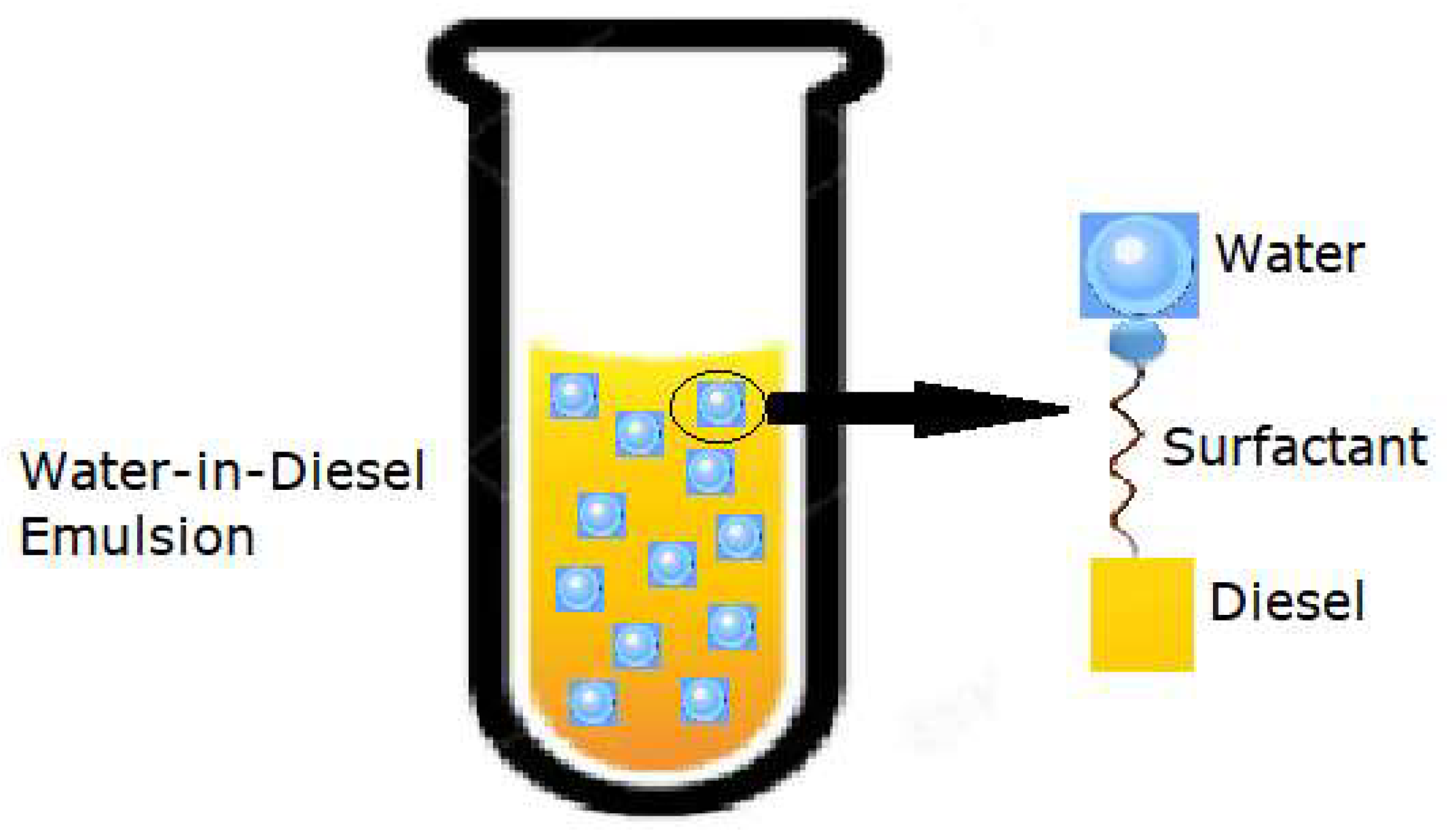
Emulsions may exhibit different forms of stability. Macroemulsions are distinguished from the other types due to their very low stability properties. Kinetically stable solutions are commonly referred to as nanoemulsions and are stable for a limited time (the dispersed droplets are held in suspension due to Brownian motion). Microemulsions are thermodynamically stable, remaining in their lowest energy state, achieving chemical equilibrium with the environment, and therefore exhibiting a long shelf-life [16,17]. Two-phase emulsions are usually divided into w/o and oil-in-water, depending on the composition of each phase [8]. WiDE are classified as w/o emulsions where diesel is the continuous phase and water is the dispersed phase. They are generally formed by a hydrocarbon, water, and one or more surfactants as the emulsifier agent, as shown in Figure 1. The surfactant’s hydrophilic head interacts with water and its hydrophobic tail associates with diesel.

Figure 1.
Dispersed water droplets in a continuous diesel phase (adapted from [18]).
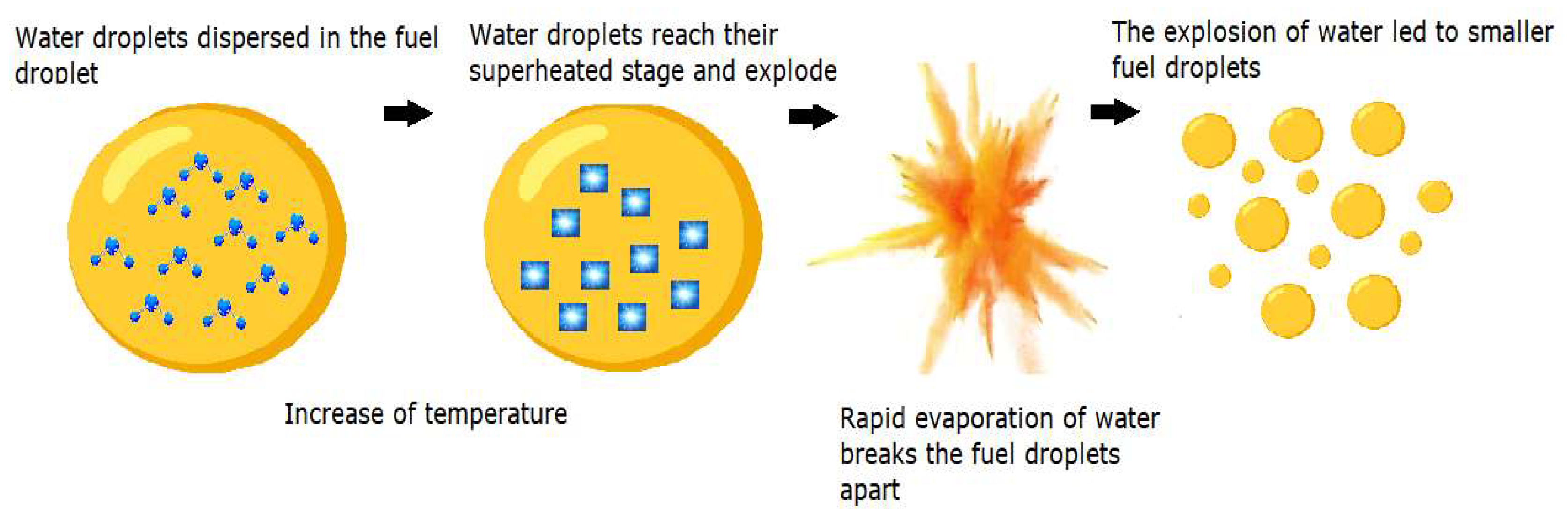
The enhanced efficiency of these emulsions in combustion can be attributed to the synergistic events of puffing and micro-explosion within the emulsion droplets [19]. When sprayed into a high-temperature combustion chamber, the occurring convective and radiative heat transfer processes heat the surface of the fuel droplets. Due to differences in the volatility of the continuous and dispersed phases (diesel and water), a swift disintegration of the parent droplets occurs [14,20]. The vapor expansions of the more volatile water droplets break and split the fuel droplets apart, inducing a secondary atomization, in the aftermath of the primary process at the injector, finely fragmenting the fuel droplets into smaller particles [21]. During this phase, the previously mentioned dual events of puffing and micro-explosion come to the forefront. The first one is characterized by the partial ejection of dispersed water from an emulsion droplet. The latter corresponds to the complete disintegration of the parent droplet [22,23]. The effective fuel droplet size distribution is enhanced, improving the surface contact area of the fuel molecules with the surrounding air and ultimately leading to a better mixture formation, more optimized combustion, and fewer emissions [24,25,26]. An example of the micro-explosion phenomenon in a fuel droplet is shown in Figure 2.
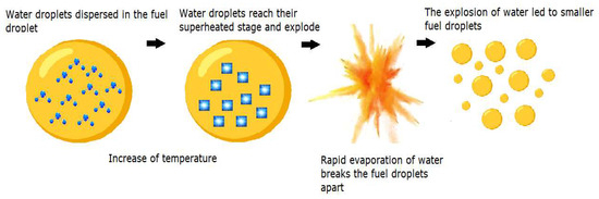
Figure 2.
Micro-explosion in a fuel droplet (adapted from [8]).
These occurrences show manifestations in the exhaust emissions following the combustion process. A reduced combustion chamber temperature due to the heat sink effect of the evaporation of water molecules, due to water’s elevated specific heat capacity and latent heat of vaporization [13], reduces the formation of thermal NOx, favored by the high temperatures which lead to the dissociation of nitrogen from atmospheric air and its association with oxygen [27]. This effect results in an extension of the ignition delay, allowing more fuel combustion in premixed mode [14]. A higher air/fuel ratio due to the presence of excess oxygen in the fuel can also help reduce fuel-rich zones in the heterogenous combustion inside the cylinder, decreasing smoke emissions [28].
Most studies regarding WiDE are performed using a hydrophobic surfactant formulation, which is ideal for emulsion stabilization at storage temperatures with specific non-ionic surfactants utilized. They are also consistent in the reduction in NOx and smoke levels, although the results for other exhaust gases and fuel efficiency differ widely [10,13,14,22,29]. However, with the increase in the fuel temperature due to fuel return to the tank during engine operation, such a formulation should not be ideal due to temperature changes. The HLB of some non-ionic surfactants is also found to decrease with temperature increases, suggesting that when choosing the surfactants at ambient temperature, this number should be higher [30]. By preparing a formulation in which the water droplets are more thoroughly dispersed and with a smaller radius, securing more stabilization at higher fuel temperatures, higher benefits are expected to be returned. On top of this, other polar solvents such as alcohols may be easily added to the emulsifiers, possibly improving some emulsion properties. A decreased kinematic viscosity difference between diesel fuel and the emulsion to be tested is also obtained due to prior heating before engine supply. This leads to the engine’s injection timing, typically optimized for diesel fuel, having a limited impact when using emulsified fuel due to its association with viscosity.
2. Materials and Methods
2.1. Emulsion Preparation
A wide variety of methods have been tested and used to develop WiDE fuels [31]. For this case, a low energy mixing method by using a magnetic stirrer for smaller samples and a mechanical agitator (mixing paddle attached to a drill) for higher volume samples was utilized. The three main components consist of diesel, water (distilled or deionized), and surfactants. For this work, EN590 diesel fuel, deionized water, and a combination of a non-ionic hydrophilic surfactant and a hydrophobic co-surfactant have been utilized. A temperature of 40 °C was selected to develop an optimal formulation. This temperature was selected based on the temperature of the fuel in the fuel tank of most diesel engines during normal operating conditions, where after the initial warming-up period, the heated fuel return gradually increases the fuel temperature in the fuel tank to these temperature values. Having the work of Fernandes as a reference [32], describing formulations for nano- and microemulsions using two surfactants and an alcohol, different trials were performed to obtain an optimized formulation consisting of 89% (m/m) diesel, 8% (m/m) deionized water, and 3% (m/m) of surfactant blend. Maintaining the diesel and water percentage constant, trial and error experiments were carried out to find the optimal surfactant to co-surfactant ratio that would produce a stable emulsion at the temperature of 40 °C. After several attempts, it was found that a ratio of 91% hydrophilic surfactant to 9% lipophilic co-surfactant was optimal for the stability of the emulsion at 40 °C. It was also found that an increase in the HLB value due to the increase in the hydrophilic surfactant percentage would increase the temperature at which the emulsion is most stable. Cocamide DEA and Span 80 were used as surfactants. Their molecular formulas and HLB values are shown in Table 1.

Table 1.
Chemical composition and hydrophilic–lipophilic balance (HLB) of the surfactants.
According to [33], the HLB of the mixture can be calculated by Equation (1):
where HLBC, HLBS, and ΦS correspond to the HLB values of Cocamide DEA, Span 80, and the mass ratio of Span 80 to the total mass of the surfactants in the mixture, respectively. This gives a HLB of 12.645 for this formulation, making it a hydrophilic blend of emulsifiers.
HLBMix = (1 − ΦS)HLBC + ΦSHLBS,
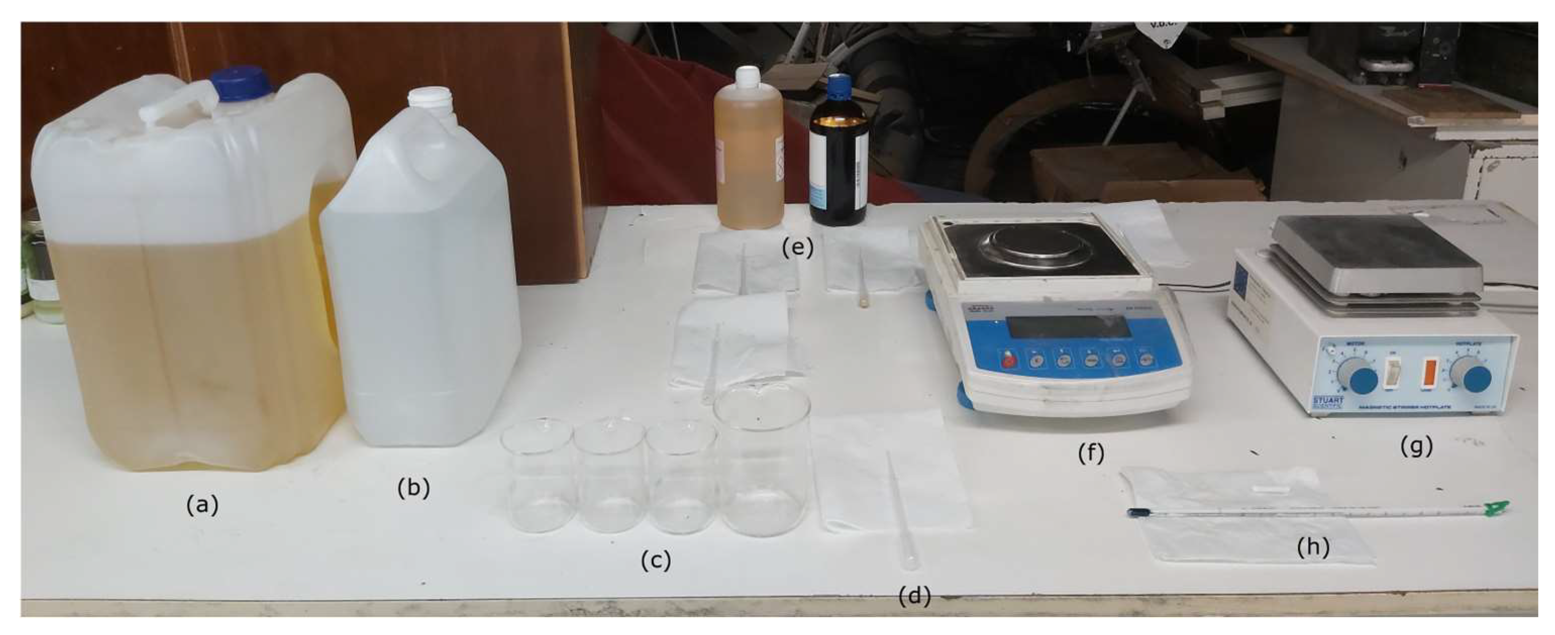
In addition to diesel, water, and surfactants, Figure 3 shows the remaining materials used in the experiments.

Figure 3.
(a) EN 590 Diesel fuel; (b) deionized water; (c) 100 mL and 200 mL beakers; (d) 3 mL plastic pipettes; (e) surfactant and co-surfactant; (f) Radwag AS 310/C/2 analytic balance; (g) Stuart Scientific SM3 magnetic stirrer; and (h) Enviro-Safe thermometer.
Samples of 50 g were prepared and posteriorly tested in a water bath to check their stability at 40 °C. The following protocol was used during the trials for emulsion preparation: place a beaker in the balance; add the corresponding weight of lipophilic surfactant; add the corresponding weight of hydrophilic surfactant; in two other beakers, weigh the corresponding amount of diesel and water; place the beaker containing the two surfactants in the magnetic stirrer; while stirring at 1000 to 1500 rpm, add diesel to the surfactants; with a pipette, gradually add the water, droplet by droplet for 5 min; for 2 more minutes, leave the beaker in the magnetic stirrer to homogenize the solution. The weighted ratio of surfactant to co-surfactant varied from 85 to 91% with increments of 2% between the trials. After each trial, the behavior of the sample was observed in a water bath at 40 °C and the best one was chosen by visual means. A flashlight was pointed to one side of the beaker and the light propagating through the solution on the opposite side was observed. This would be an indication that the dispersed water particle size was low enough (1 to 100 nm), with enough polydispersity, to make a stabilized emulsion at the specified temperature. In Figure 4 it is possible to see the obtained transparent emulsion consisting of 89% diesel, 8% water, and 3% surfactant formulation.
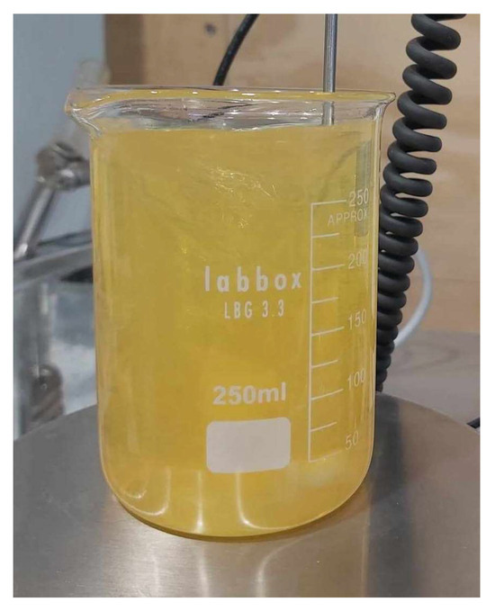
Figure 4.
The 8% Water-in-Diesel Emulsion (WiDE) at T = 40 °C.
Density, Viscosity and Heating Value
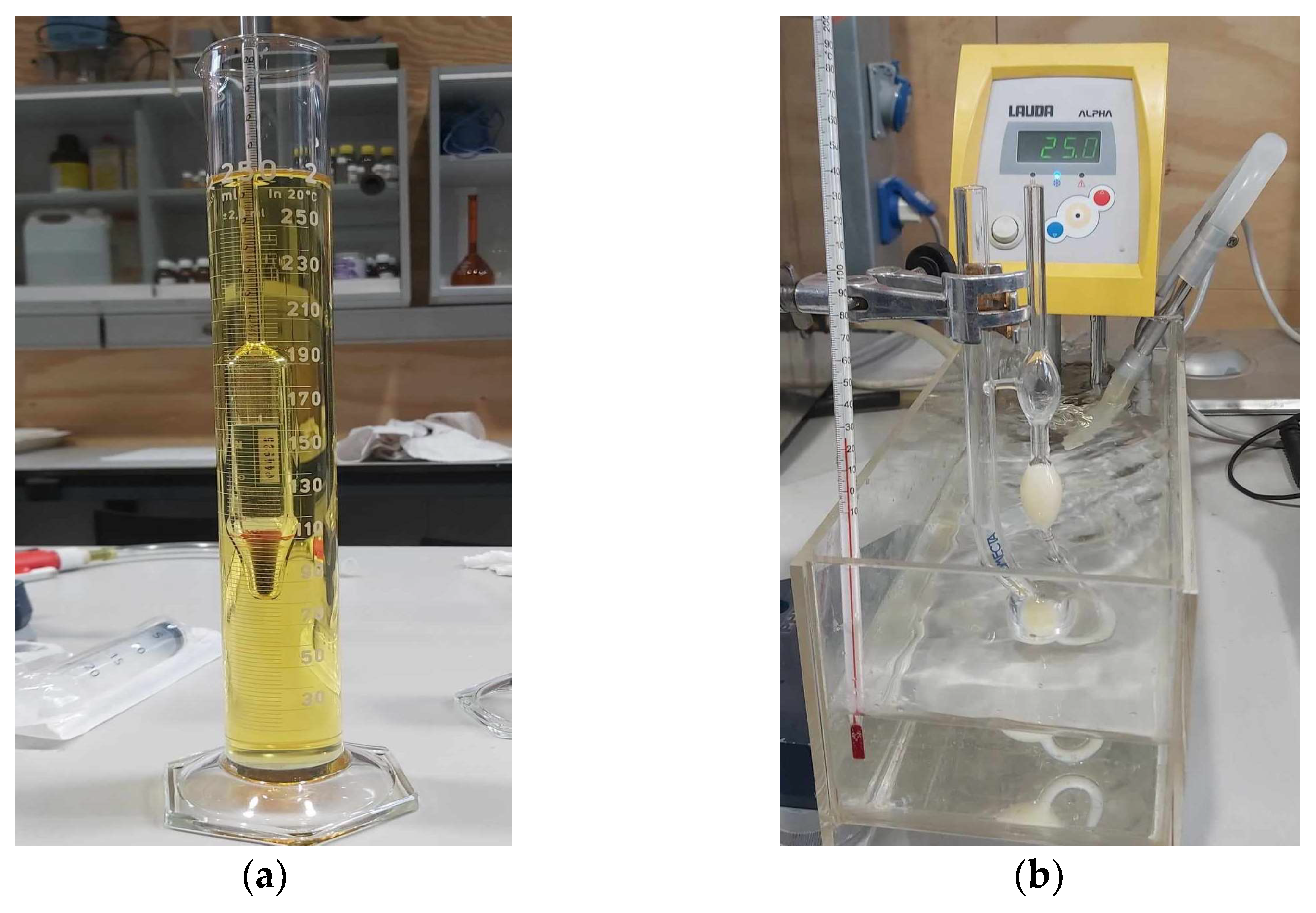
In a diesel engine, combustion is an unsteady process occurring simultaneously at many regions in a very non-homogenous mixture [34]. Following the injection phase, atomization, vaporization, mixing, self-ignition, and combustion occur. Numerous factors can affect the combustion process, with fuels exhibiting unique behaviors depending on their inherent properties. The spray, mixing, and energy release rate are affected by those properties. Figure 5 shows the equipment used for density and viscosity measurements. A thermostatic bath was used to induce temperature variation. Three measurements were carried out for each temperature and fuel combination.

Figure 5.
(a) Densimeter; (b) Cannon-Fenske viscometer in a 25 °C thermostatic bath.
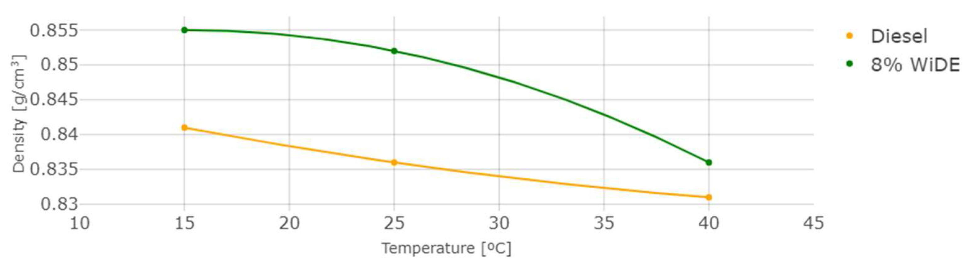
The measured density and kinematic viscosity of the two different fuels are shown in Figure 6 and Figure 7.

Figure 6.
Density at different temperatures.
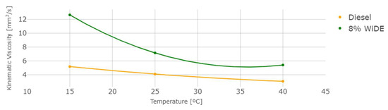
Figure 7.
Kinematic viscosity at different temperatures.
As temperature increases, density and viscosity decrease in both fuels. These values are higher for the emulsion fuel at all temperatures, which can be explained by the presence of water and surfactant in the blend leading to a denser and more viscous mixture. In general, an increase in the viscosity of a diesel fuel will result in a corresponding increase in the ignition delay. This is because a more viscous fuel will be more resistant to flow and will take longer to vaporize and mix with the oxygen in the combustion chamber. As a result, it will take longer for the fuel to ignite and start the combustion process.
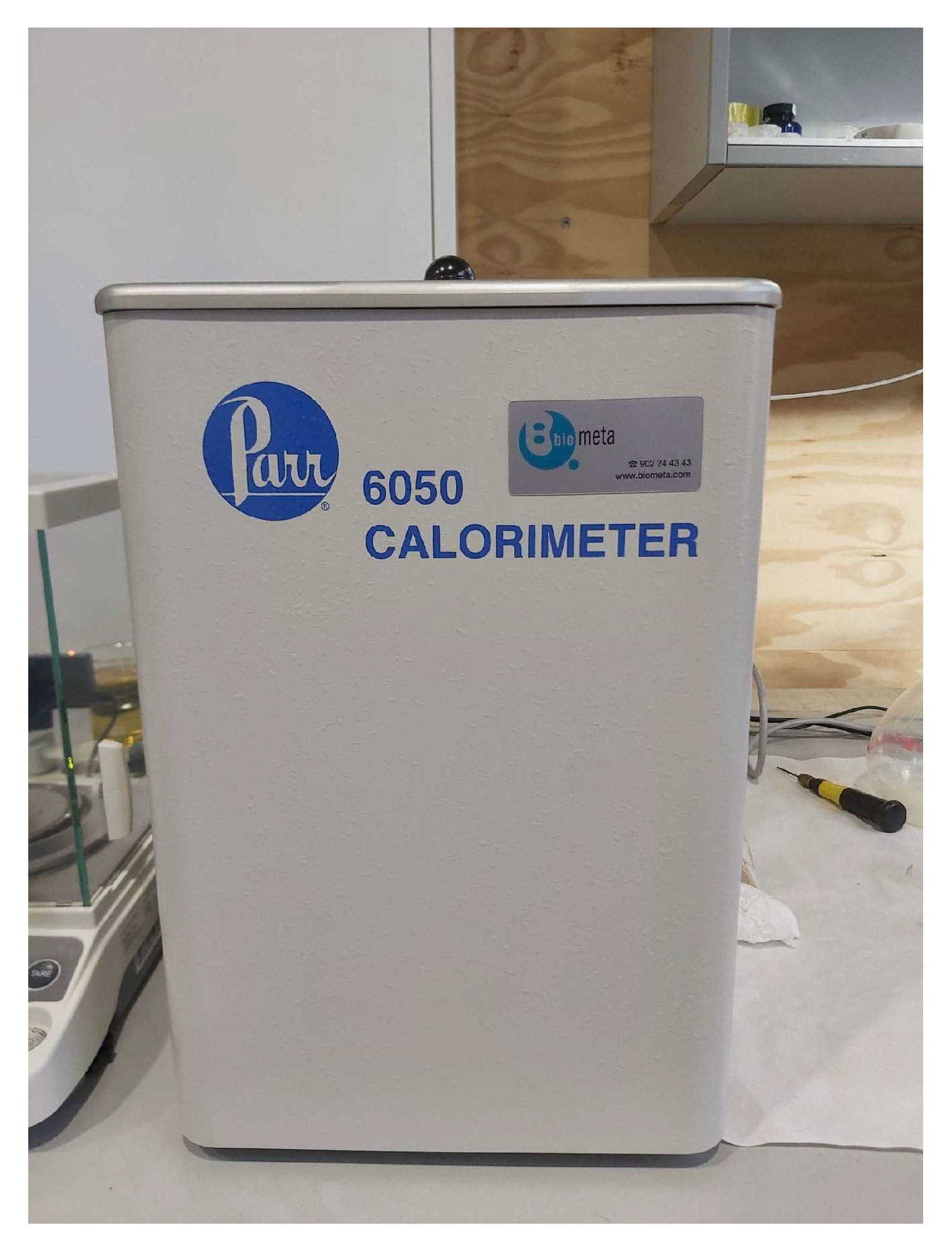
A bomb calorimeter was utilized, shown in Figure 8, to measure the amount of heat exchanged in the chemical reaction of both fuels.
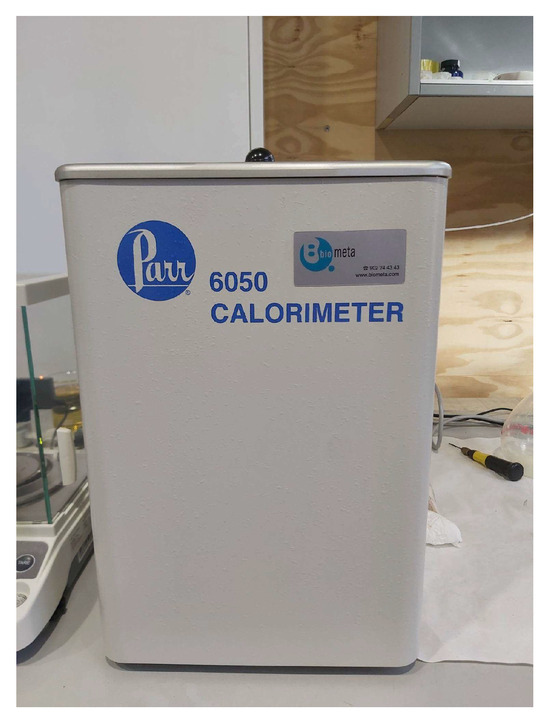
Figure 8.
Parr 6050 bomb calorimeter.
After performing the necessary calculations to convert the Higher Heating Value at constant volume (HHVv) given by the calorimeter to the Lower Heating Value at constant pressure (LHVp), representative of the diesel engine combustion cycle, where water vapor is assumed to remain in a gaseous state after combustion, and does not consider the recovery of its latent heat of vaporization [35], Table 2 was obtained, using densities values at 15 °C.
Table 2.
Heating values of the different fuels.
As expected, the heating value of the emulsion is lower than diesel since water does not contribute to the energy content of the fuel. However, it is possible to see that the surfactant blend significantly contributes to the increase in this value, since if only the diesel portion was considered as the unique energy contributing source, according to Equation (2), the HHV89 would be 40.4861 MJ/Kg:
where HHV89 is the HHVv in MJ/Kg of the emulsion, considering diesel as the only energy-contributing factor in the mixture.
HHV89 = 45.49 × 0.89,
2.2. Engine Testing
Figure 9 shows the engine in which the experiments were conducted. Table 3 shows its details. An eddy current dynamometer was used to supply load and to measure speed and torque values. Fuel consumption was measured with a balance by monitoring the difference in weight over time.
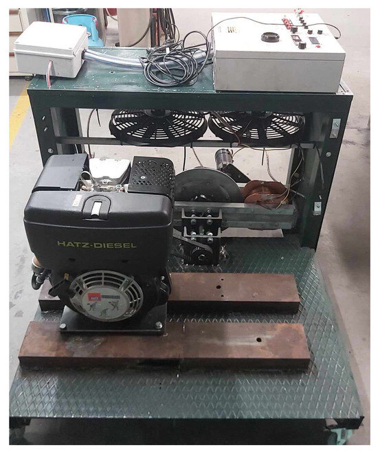
Figure 9.
Hatz 1B-40 diesel engine.
Table 3.
Hatz 1B-40 specifications.
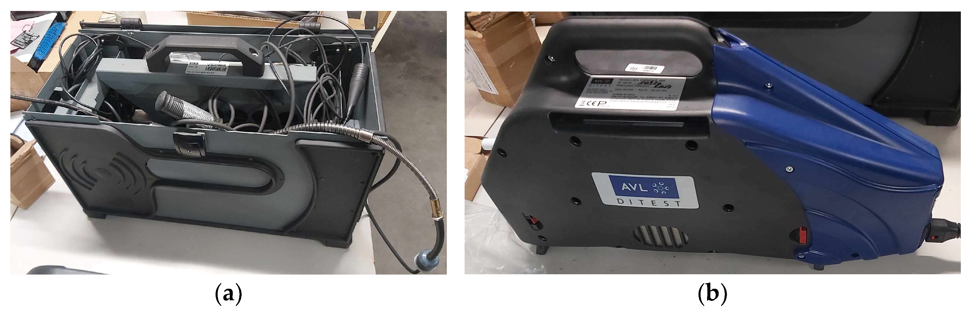
Figure 10 shows the exhaust gas analyzer and opacimeter used to measure emissions. Table 4 and Table 5 show the specifications of the equipment.
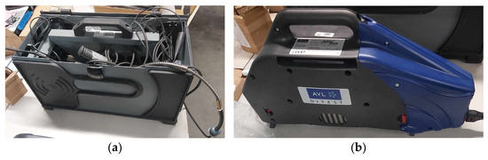
Figure 10.
(a) AVL DiTest gas 1000 model 2301 5-gas analyzer; (b) AVL DiSmoke 480 opacimeter.
Table 4.
AVL DiTest gas 1000 model 2301.
Table 5.
AVL DiSmoke 480.
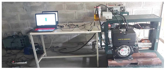
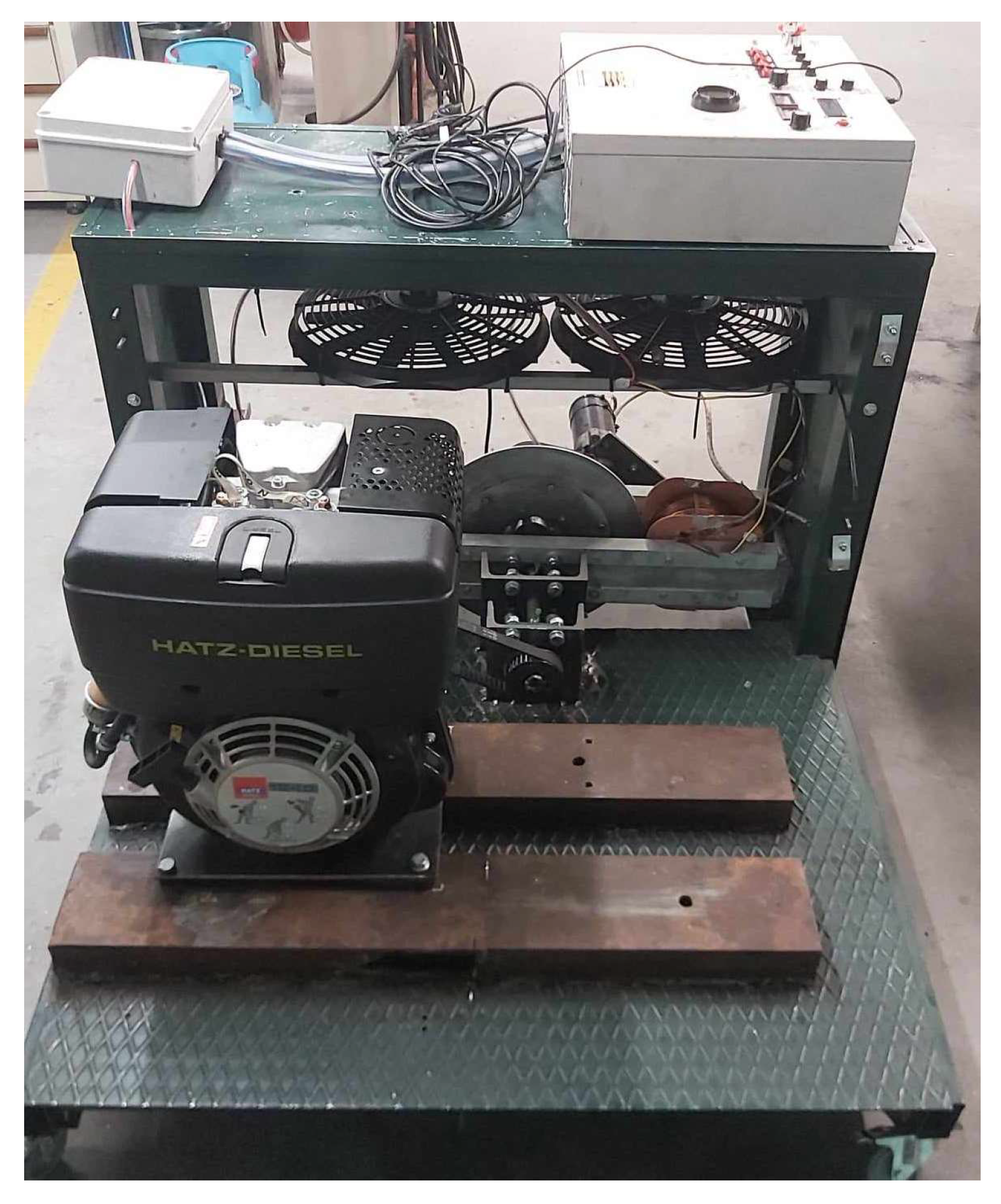
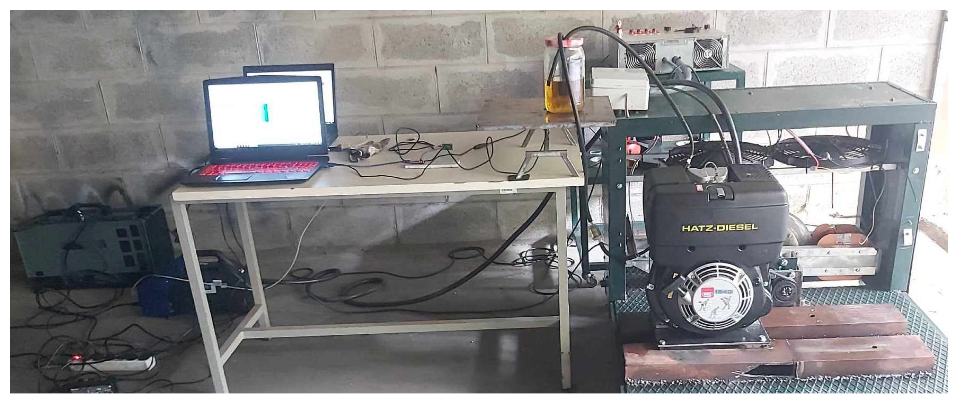
Figure 11.
Test-bench.
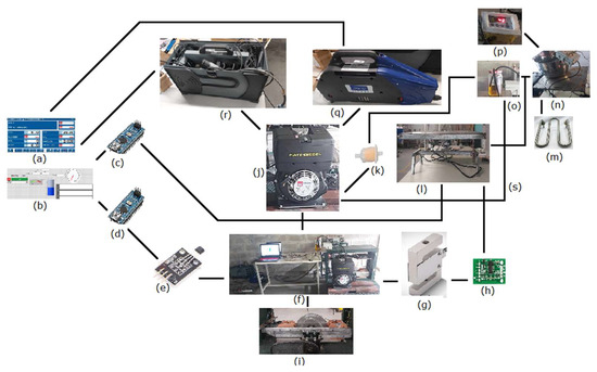
Figure 12.
Test-bench layout: (a) emission data acquisition; (b) performance data acquisition; (c) arduino 1; (d) arduino 2; (e) hall sensor (speed); (f) test-bench; (g) load cell for torque measurement; (h) HX711 load cell amplifier; (i) eddy current dynamometer; (j) diesel engine; (k) fuel filter; (l) load cell and fuel tank balance for fuel consumption measurement; (m) heating unit (variable resistor); (n) thermostatic bath for emulsion fuel tank; (o) diesel fuel tank; (p) fuel temperature sensor; (q) opacimeter; (r) gas analyzer; and (s) fuel return.
The engine was manually started and left running to undergo a warming-up phase. After reaching similar operating temperatures on both fuels, confirmed with an IR thermometer on the engine’s block, it was accelerated to 3000 rpm, and a constant load was applied simultaneously to both coils by managing the current and voltage in the dynamometer controller. This load corresponded to nearly 75% of the engine’s maximum torque, by applying current and voltage to energize the dynamometer coils (~1 A and ~18.75 V for each coil) leading to induced eddy currents in the rotating aluminum disk, producing a braking torque registered in the load cell. The gas analyzer and opacimeter probes were then inserted in the engine’s exhaust system, and after a stabilization period, results were recorded every 250 ms between 30 and 60 s for each condition, by utilizing LabVIEW 2019 19.0f2. software for both arduinos data and AVL DSS 2.0. software for exhaust gases data. After saving the results for the first operating condition, the engine speed was decreased to 2500 rpm by adjusting the accelerator pedal position accordingly. The same procedure was followed for 2000 rpm, 1500 rpm, and for both fuels. For the emulsion fuel, a thermostatic bath set to 40 °C with polyethylene glycol 400 as fluid was employed to maintain a uniform temperature, within which the formulation was previously optimized (Figure 12n). The data was imported from .csv to R 4.1.3. software to be evaluated, where various results were withdrawn. For each engine condition, the mean value of torque, speed, and each exhaust gas concentration was calculated from the data obtained. The fuel consumption was calculated by applying a linear regression on the weight loss of the fuel tank in the balance during a specific time. The slope of the equation corresponded to the fuel consumption in g/s.
3. Results and Discussion
After collecting the different results, R programming software was utilized for pre-processing and data analysis. Since the load applied in the dynamometer was constant, the braking torque exerted by the eddy currents induced on the aluminum disk has to be the same for a given speed, and independent of the fuels tested (Figure 13). The same happens for power which is proportional to the engine’s rotating speed (Figure 14). The engine’s performance (Figure 13, Figure 14, Figure 15 and Figure 16) and emissions (Figure 17, Figure 18, Figure 19, Figure 20, Figure 21 and Figure 22) plots are shown next. The applied load corresponds to 75% of the engine’s maximum considered load.
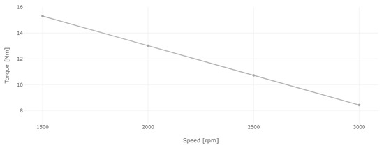
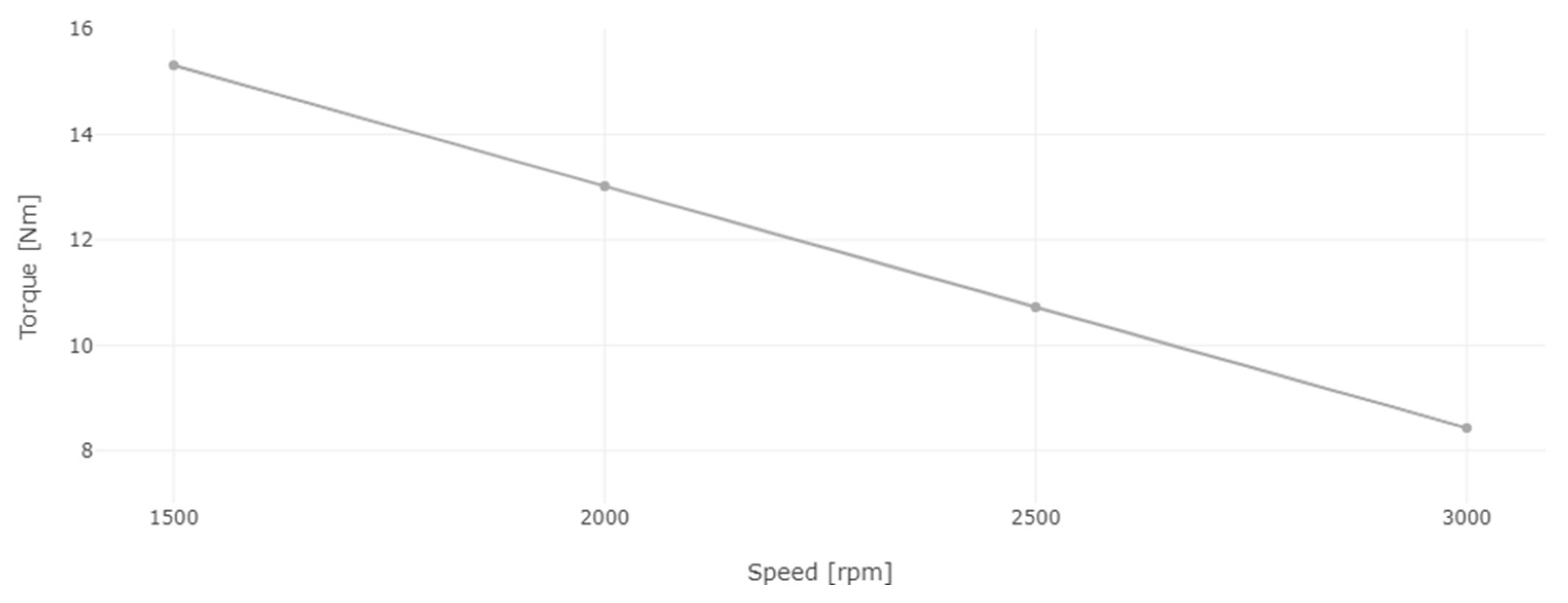
Figure 13.
Engine torque for diesel and 8% WiDE.

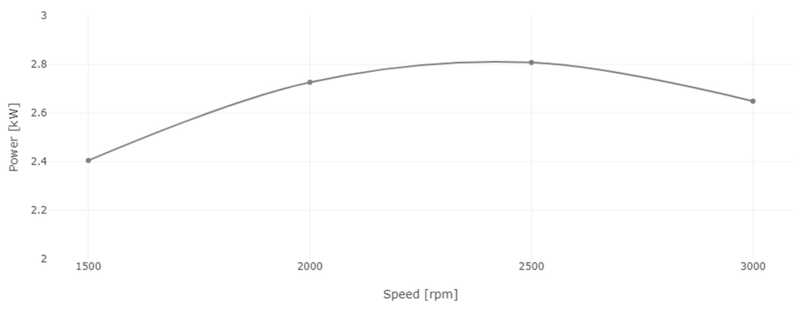
Figure 14.
Engine power for diesel and 8% WiDE.
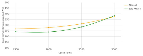
Figure 15.
Engine specific fuel consumption.
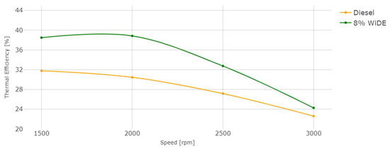
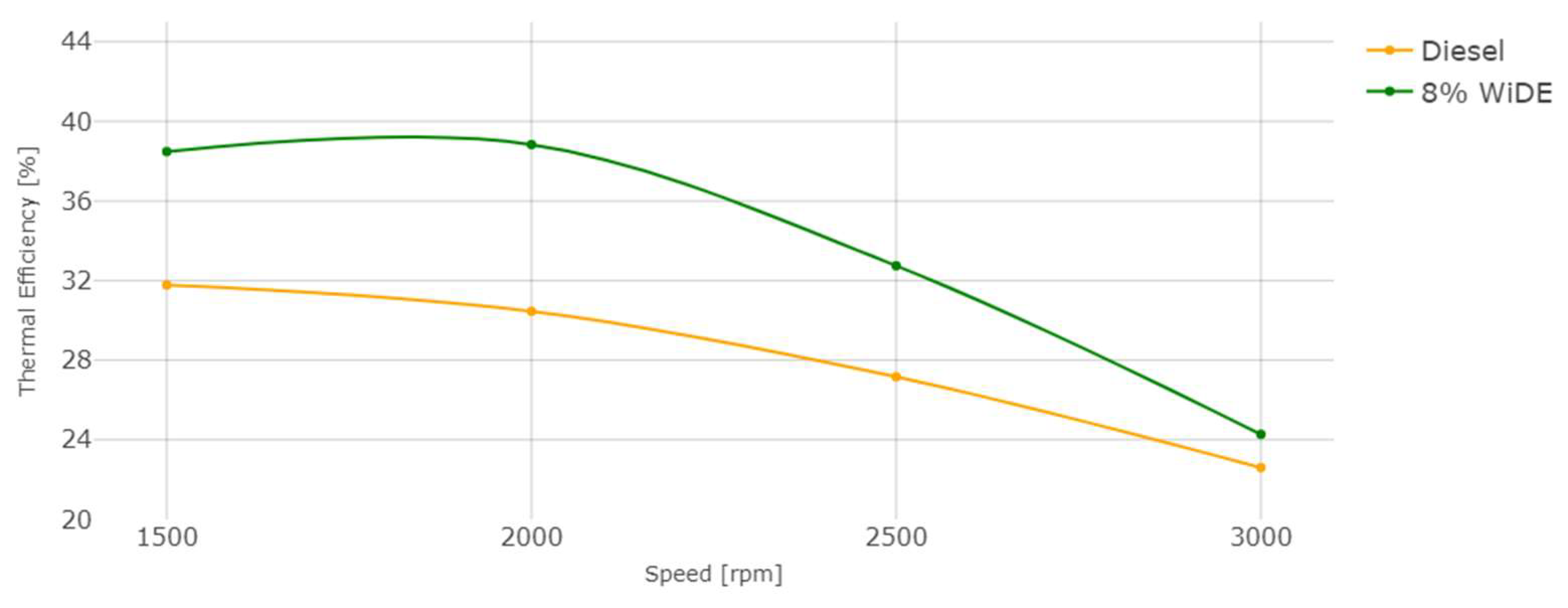
Figure 16.
Engine thermal efficiency.
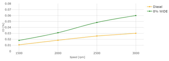
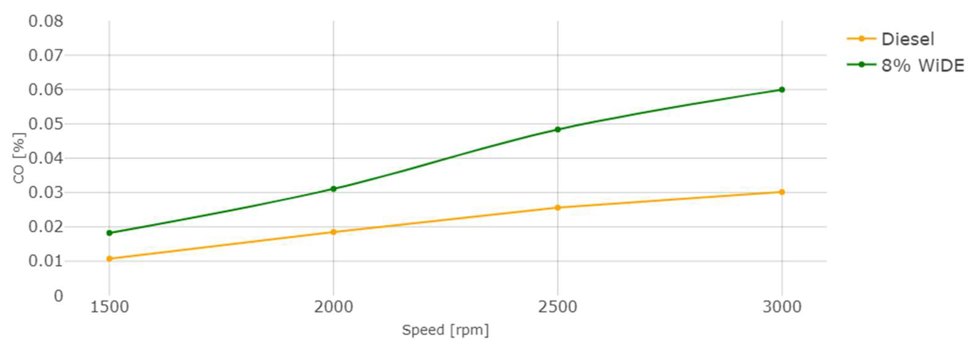
Figure 17.
Carbon monoxide (CO) emissions.

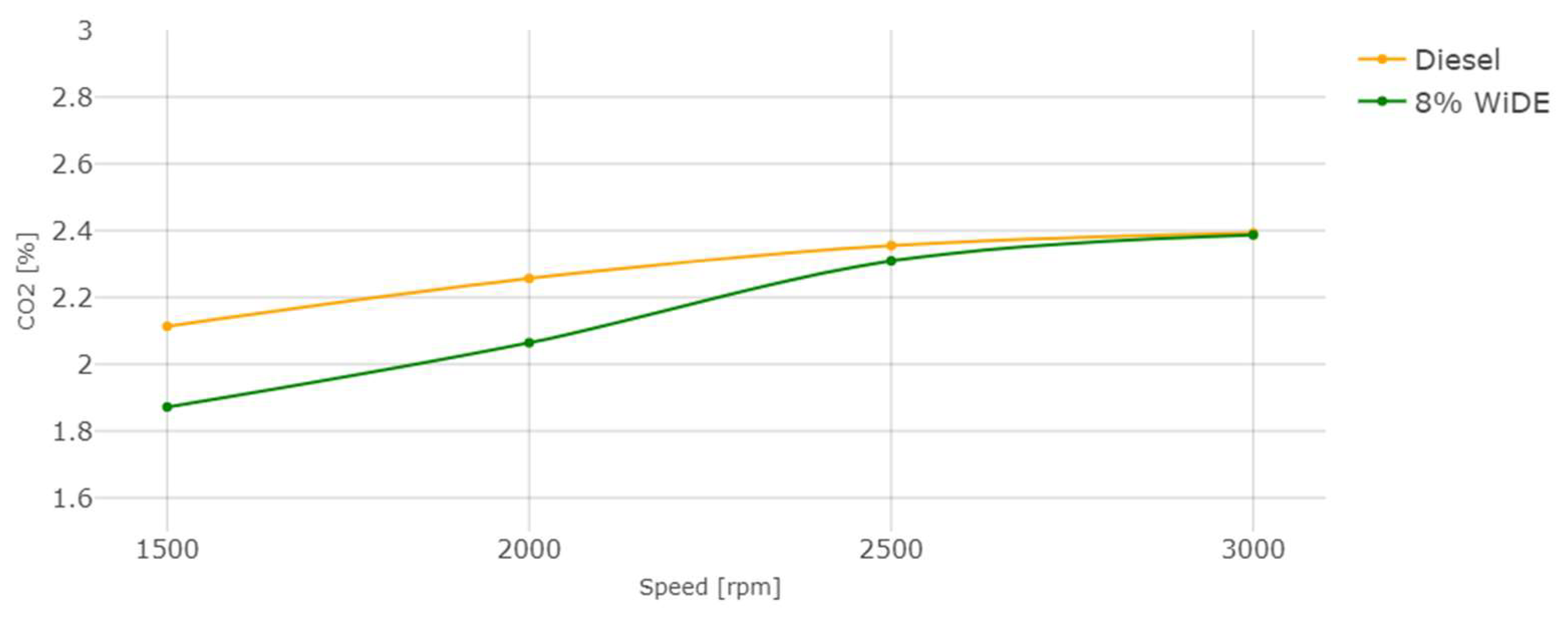
Figure 18.
Carbon dioxide (CO2) emissions.

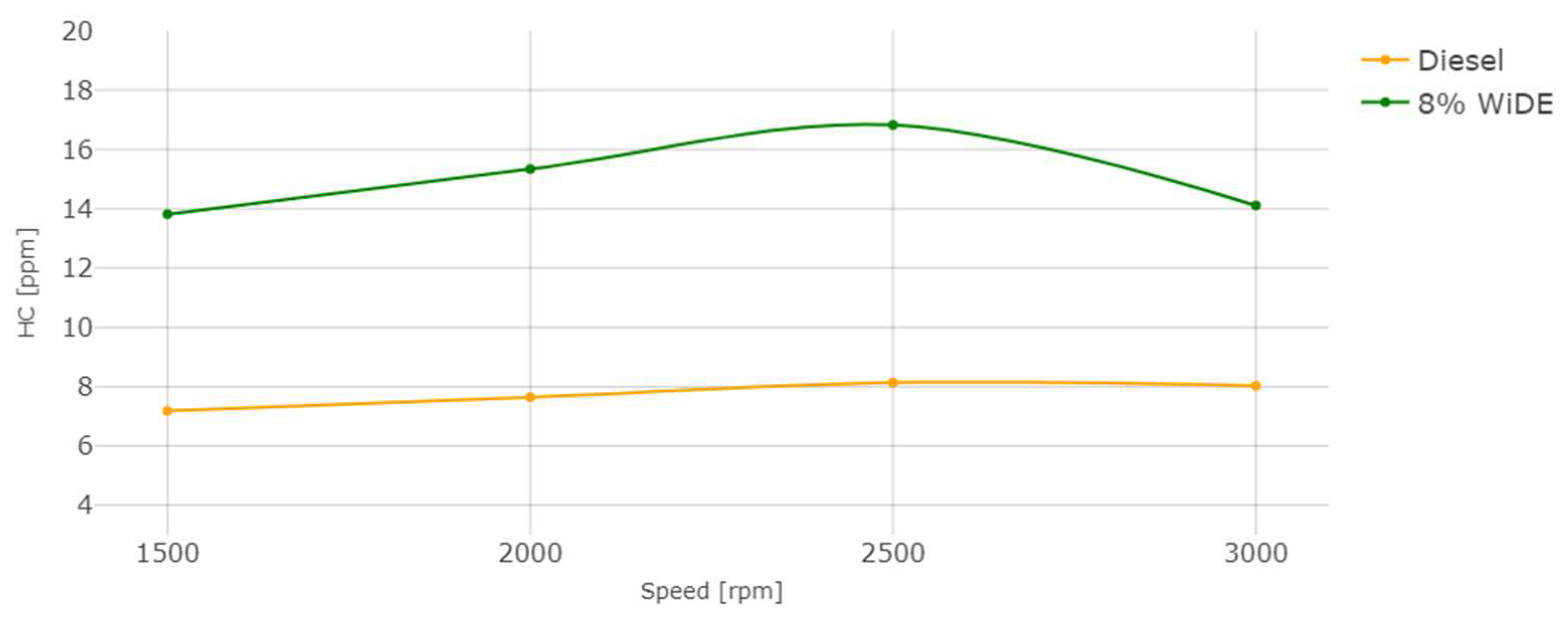
Figure 19.
Hydrocarbons (HC) emissions.
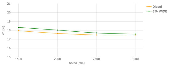
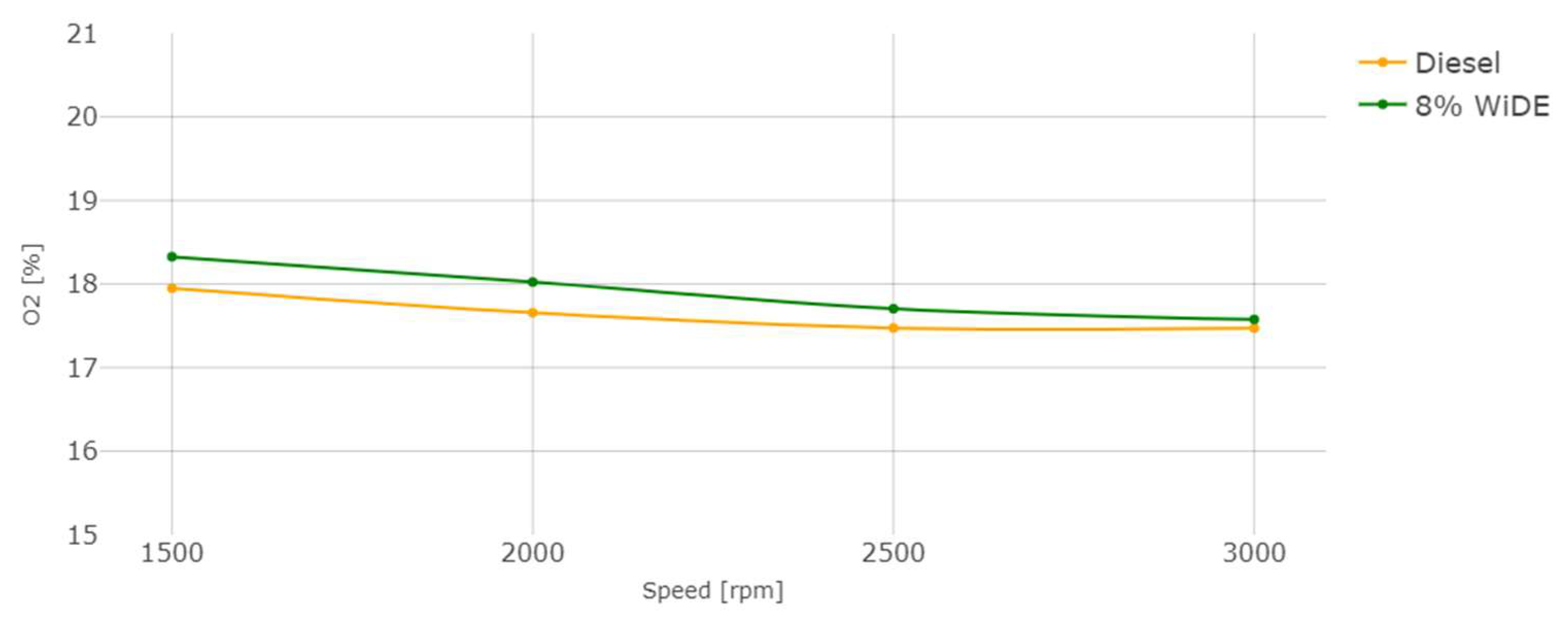
Figure 20.
Oxygen (O2) emissions.
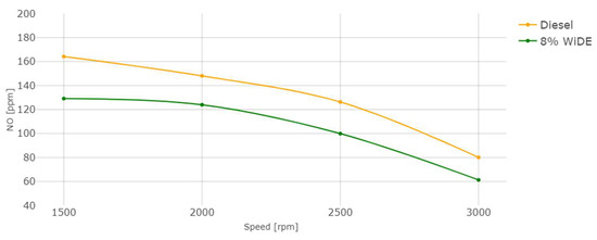
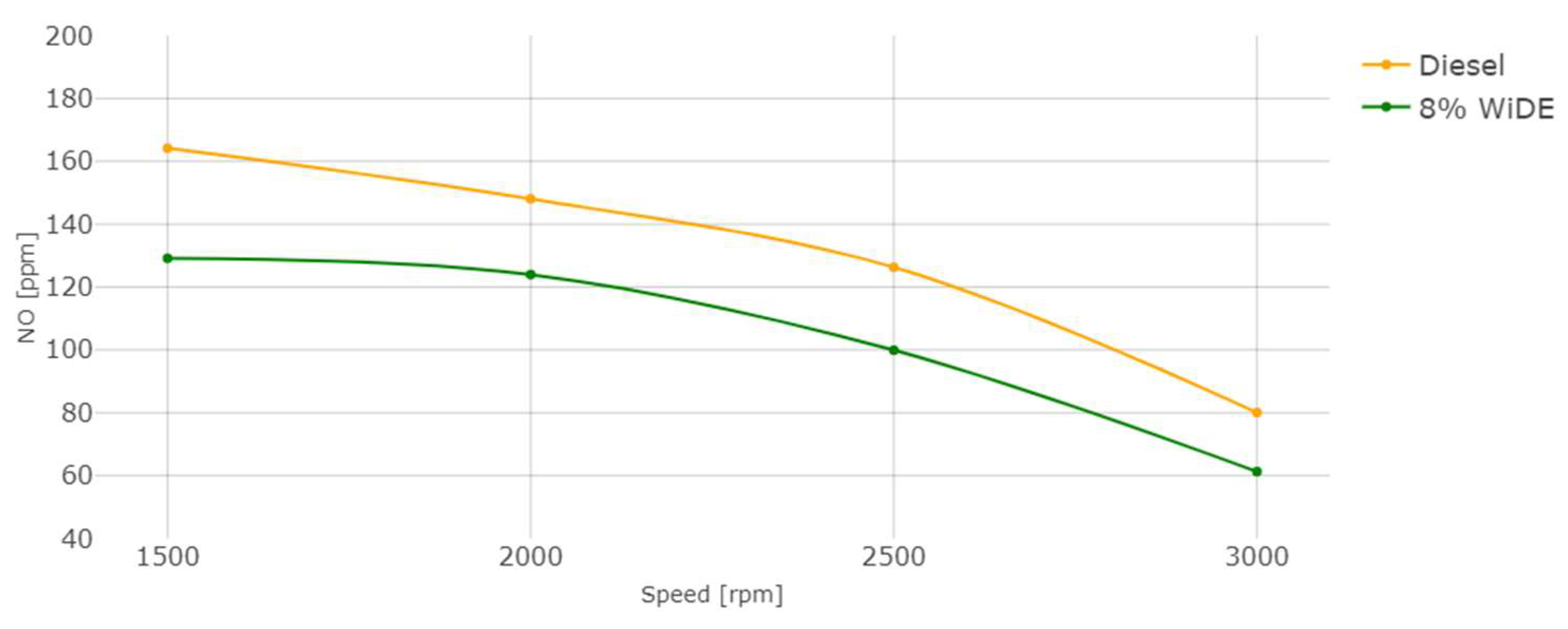
Figure 21.
Nitric oxide (NO) emissions.
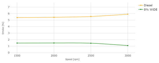
Figure 22.
Smoke emissions.
3.1. Performance
After setting a constant load on the dynamometer, the engine speed was varied by decreasing the position of the accelerator pedal. As seen in Figure 13, the engine torque increased linearly with the decrease in engine speed from 3000 rpm to 1500 rpm, which is characteristic of this electromagnetic brake, as the eddy currents on the dynamometer rotating disk are opposing the rotation of the engine. The slower the engine is running, the higher the force produced in the coils structure, where the load cell is placed due to the increased braking effect and thus, higher torque is obtained. If the engine speed was continuously decreased, it would reach a point where the engine would not be able to keep up with the applied load. The engine would stall, and the torque would rapidly decrease to zero due to a stationary disk.
Power and torque are directly proportional to each other. The power of the engine is calculated from torque and speed, and as seen in Figure 14, it increased from 1500 rpm, peaking at 2500 rpm, after which it started to decrease until 3000 rpm due to lower torque at this speed condition.
Regarding engine performance, the SFC of both fuels increases overall with an increase in speed, probably due to the decrease in torque with increasing engine speed. The SFC of the emulsified fuel is lower from 1500 rpm to 2500 rpm, and slightly higher at 3000 rpm. This can be a good indication of better combustion efficiency of the emulsified fuel because a lower mass flow rate is needed compared to diesel, to obtain the same engine power during steady engine operation at different speeds.
Thermal efficiency is inversional proportional to SFC and LHV, according to Equation (3):
where TE is thermal efficiency in %, SFC is specific fuel consumption in g/kWh, and LHV is the lower heating value of the fuel, in MJ/Kg. The LHV of the emulsion is lower and corresponds to 91.16% of diesel’s LHV. From 1500 rpm to 2500 rpm, the SFC of the emulsion is also lower, which leads to a big increase in the thermal efficiency over diesel. At 3000 rpm, even though the SFC of the emulsion is higher, its lower LHV is enough to maintain a slightly better thermal efficiency compared to diesel. It can also be seen that the overall thermal efficiency decreases with the increase in engine speed, similar to engine torque.
TE = 360,000/(SFC.LHV),
This increased efficiency can also be attributed to the occurrences of microexplosions and puffing in the emulsion droplets, increasing the force acting on the piston in the expansion stroke and reducing the amount of fuel injection needed to maintain the same torque at a constant speed, resulting in more complete combustion.
3.2. Emissions
CO emissions are a result of incomplete combustion. In accordance with most of the literature, a significant increase in CO emissions for the emulsion at all conditions was observed. For both fuels, an increase in engine speed leads to an increase in CO emissions. This can be attributed to the presence of excess carbon atoms from the surfactants that were not fully combusted (possibly due to lower combustion temperatures), leading to their presence in the exhaust manifold. Those increases may also be linked to the increased viscosity of the emulsified fuel compared to diesel and different spray characteristics after the injector. The higher cetane number of diesel fuel due to a shorter ignition delay may also be a reason for the reduced CO emissions and more complete combustion.
From Figure 18, it is possible to see that an increase in engine speed (decrease in engine torque) leads to a decrease in CO2 emissions. These emissions are significantly lower for the emulsified fuel at 1500 rpm and 2000 rpm, and not significantly lower at 2500 rpm and 3000 rpm. The values between the two fuels become more similar with the increase in engine speed. The lower carbon content of the emulsified fuel can be a reason for this decrease, since the higher carbon content of diesel may result in higher CO2 emissions, because there is more carbon available to oxidize and form CO2.
The HC emissions also occur due to incomplete combustion of the fuel, strongly influenced by the air/fuel ratio. In accordance with most of the literature, a significant increase in HC emissions at all conditions was observed. This can be attributed to the presence of excess carbon and hydrogen atoms from the surfactants that were not fully combusted, leading to their presence in the exhaust manifold. The occurrence of spray wall impingement from the increased spray penetration (due to microexplosions) or the lower combustion chamber temperatures can also be responsible for these higher emissions. Those increases may also be linked to the increased viscosity of the emulsified fuel compared to diesel and different spray characteristics after the injector.
As can be seen, O2 emissions between both fuels are very similar. They decrease with the increase in engine speed and are slightly higher for the emulsified fuel. The presence of water and the increased content of oxygen atoms, when compared to diesel fuel, may explain this occurrence, which can be found in oxygen-enriched fuels.
As seen in Figure 21, the increase in torque (decrease in engine speed) leads to an increase in NO emissions, due to the increase in the combustion temperature and possibly oxygen content (Figure 20). In accordance with the literature, a significant decrease in NO was also registered for the emulsion fuel at all engine speeds compared to diesel. The evaporation of water droplets leads to a decrease in the combustion chamber temperature and prevents the association of nitrogen and oxygen existing in the air, which is responsible for the formation of thermal NO, the main contributor to overall NO emissions. The heat sink effect of water is the main factor responsible for this outcome since the heat resulting from the combustion that would be lost through the cylinder walls is absorbed by the water molecules to change its physical state.
The reduction in smoke levels, similar to the literature, was the most significant benefit of utilizing the emulsified fuel, with similar percentages across all engine speeds. This can be explained by a reduction in the fuel-rich zones (characteristic of diesel engine combustion) due to the increased oxygen content present in the water phase, a higher mixing rate due to the secondary atomization, and a longer ignition delay due to the higher viscosity of the fuel, which may take longer to vaporize, mix and ignite, initiating the combustion process.
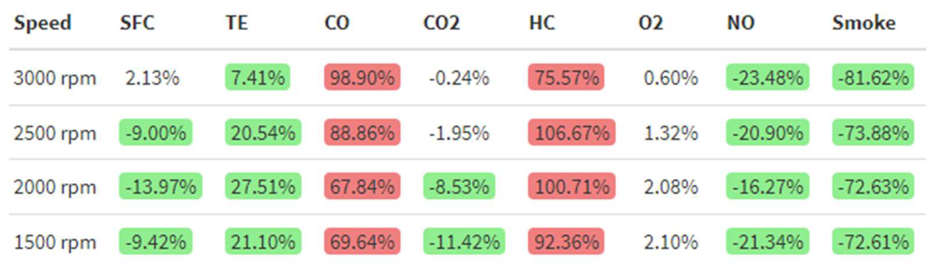
After obtaining the different plots, Figure 23 was obtained by applying Equation (4) to each parameter to calculate the percentage differences between the emulsion and diesel fuel:
where %Diff is the percentage difference of the emulsion over diesel, in %, WiDEp is the emulsified fuel parameter and Dieselp is the diesel fuel parameter. Red-colored cells represent a worsening above 5% of the parameter while using emulsified fuel over diesel, while green-colored ones represent an improvement. White-colored cells mean no significant changes using a 95% confidence interval were observed.
%Diff = 100(WiDEp − Dieselp)/Dieselp,
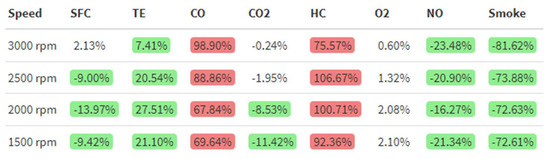
Figure 23.
Percentage differences between 8% WiDE and diesel.
4. Conclusions
This work showed that developing a hydrophilic formulation for WiDE to be optimized at the engine’s operating temperature and not for storage conditions can significantly improve its thermal efficiency and significantly reduce the emissions of CO2, NO, and smoke. On the downside, CO and HC emissions were found to be significantly higher when compared to base diesel fuel. Moreover, the higher HLB of the formulation allows for other polar solvents such as alcohols to be more easily added to the mixture, possibly allowing the enhancement of some fuel properties such as density and viscosity at the same temperature, which may have a positive effect on fuel atomization.
Author Contributions
Conceptualization, P.O. and F.B.; methodology, P.O. and F.B.; software, P.O.; validation, P.O. and F.B.; formal analysis, P.O.; investigation, P.O. and F.B.; resources, P.O. and F.B.; data curation, P.O.; writing—original draft preparation, P.O.; writing—review and editing, P.O. and F.B.; visualization, P.O. and F.B.; supervision, F.B.; project administration, F.B.; funding acquisition, P.O. and F.B. All authors have read and agreed to the published version of the manuscript.
Funding
This research was funded by FCT (Faculdade de Ciências e Tecnologia), grant number 2021.07535.BD and C-MAST (Center for Mechanical and Aerospace Technology) https://doi.org/10.54499/UIDB/00151/2020—Base (accessed on 9 March 2024) and https://doi.org/10.54499/UIDP/00151/2020—Programmatic (accessed on 9 March 2024).
Data Availability Statement
The raw data supporting the conclusions of this article will be made available by the authors on request.
Acknowledgments
We would like to thank the University of Castilla-La Mancha and C-MAST (Centre for Mechanical and Aerospace Technology) for providing the necessary space, materials, and equipment to develop the laboratory and experimental portion of this work, respectively.
Conflicts of Interest
The authors declare no conflicts of interest.
References
- Ağbulut, Ü.; Sarıdemir, S. A general view to converting fossil fuels to cleaner energy source by adding nanoparticles. Int. J. Ambient Energy 2021, 42, 1569–1574. [Google Scholar] [CrossRef]
- Mustayen, A.G.M.B.; Rasul, M.G.; Wang, X.; Negnevitsky, M.; Hamilton, J.M. Remote areas and islands power generation: A review on diesel engine performance and emission improvement techniques. Energy Convers. Manag. 2022, 260, 115614. [Google Scholar] [CrossRef]
- Mohd Tamam, M.Q.; Yahya, W.J.; Ithnin, A.M.; Abdullah, N.R.; Kadir, H.A.; Rahman, M.M.; Rahman, H.A.; Abu Mansor, M.R.; Noge, H. Performance and emission studies of a common rail turbocharged diesel electric generator fueled with emulsifier free water/diesel emulsion. Energy 2023, 268, 126704. [Google Scholar] [CrossRef]
- Vijay Kumar, M.; Babu, A.V.; Reddy, C.R.; Pandian, A.; Bajaj, M.; Zawbaa, H.M.; Kamel, S. Investigation of the combustion of exhaust gas recirculation in diesel engines with a particulate filter and selective catalytic reactor technologies for environmental gas reduction. Case Stud. Therm. Eng. 2022, 40, 102557. [Google Scholar] [CrossRef]
- Wijeyakulasuriya, S.; Kim, J.; Probst, D.; Srivastava, K.; Yang, P.; Scarcelli, R.; Senecal, P.K. Enabling Powertrain Technologies for Euro 7/VII Vehicles with Computational Fluid Dynamics. Transp. Eng. 2022, 9, 100127. [Google Scholar] [CrossRef]
- Woo, S.; Lee, K. Effect of injection strategy and water content on water emulsion fuel engine for low pollutant compression ignition engines. Fuel 2023, 343, 127809. [Google Scholar] [CrossRef]
- Marzuki, N.H.C.; Wahab, R.A.; Hamid, M.A. An overview of nanoemulsion: Concepts of development and cosmeceutical applications. Biotechnol. Biotechnol. Equip. 2019, 33, 779–797. [Google Scholar] [CrossRef]
- Vellaiyan, S. Recent advancements in water emulsion fuel to explore efficient and cleaner production from various biodiesels: A retrospective review. Renew. Sustain. Energy Rev. 2023, 187, 113704. [Google Scholar] [CrossRef]
- Kapadia, H.; Brahmbhatt, H.; Dabhi, Y.; Chourasia, S. Investigation of emulsion and effect on emission in CI engine by using diesel and bio-diesel fuel: A review. Egypt. J. Pet. 2019, 28, 323–337. [Google Scholar] [CrossRef]
- Jhalani, A.; Sharma, D.; Soni, S.L.; Sharma, P.K. Effects of process parameters on performance and emissions of a water-emulsified diesel-fueled compression ignition engine. Energy Sources Part A Recover. Util. Environ. Eff. 2023, 45, 4242–4254. [Google Scholar] [CrossRef]
- Jin, C.; Wei, J. The combined effect of water and nanoparticles on diesel engine powered by biodiesel and its blends with diesel: A review. Fuel 2023, 343, 127940. [Google Scholar] [CrossRef]
- Anil, M.D.; Hemadri, V.B.; Swamy, M. Experimental investigation on impact of water in diesel emulsion in a single-cylinder research diesel engine. Int. J. Ambient Energy 2023, 44, 399–412. [Google Scholar] [CrossRef]
- Gowrishankar, S.; Krishnasamy, A. Emulsification—A promising approach to improve performance and reduce exhaust emissions of a biodiesel fuelled light-duty diesel engine. Energy 2023, 263, 125782. [Google Scholar] [CrossRef]
- Mondal, P.K.; Mandal, B.K. A comparative study on the performance and emissions from a CI engine fuelled with water emulsified diesel prepared by mechanical homogenization and ultrasonic dispersion method. Energy Rep. 2019, 5, 639–648. [Google Scholar] [CrossRef]
- Woo, S.; Kim, W.; Lee, J.; Lee, K. Fuel properties of water emulsion fuel prepared using porous membrane method for low pollutant engine at various temperatures. Energy Rep. 2021, 7, 6638–6650. [Google Scholar] [CrossRef]
- Noor El-Din, M.R.; El-Hamouly, S.H.; Mohamed, H.M.; Mishrif, M.R.; Ragab, A.M. Water-in-diesel fuel nanoemulsions: Preparation, stability and physical properties. Egypt. J. Pet. 2013, 22, 517–530. [Google Scholar] [CrossRef]
- Deore, S.L.; Kale, S.N. Emulsion Micro Emulsion and Nano Emulsion: A Review. Syst. Rev. Pharm. 2017, 8, 39–47. [Google Scholar] [CrossRef]
- Patel, K.R.; Dhiman, V.D. A review on emission and performance of water diesel micro-emulsified mixture-diesel engine. Int. J. Environ. Sci. Technol. 2022, 19, 8027–8042. [Google Scholar] [CrossRef]
- Sazhin, S.S.; Rybdylova, O.; Crua, C.; Heikal, M.; Ismael, M.A.; Nissar, Z.; Aziz, A.R.B.A. A simple model for puffing/micro-explosions in water-fuel emulsion droplets. Int. J. Heat Mass Transf. 2019, 131, 815–821. [Google Scholar] [CrossRef]
- Wang, J.; Zhang, Q.; Wang, X.; Xu, J. Micro-explosion characteristics and mechanism of multi-component fuel droplet with high volatility differential. Fuel 2023, 333, 126370. [Google Scholar] [CrossRef]
- Islamova, A.; Tkachenko, P.; Shlegel, N.; Kuznetsov, G. Secondary Atomization of Fuel Oil and Fuel Oil/Water Emulsion through Droplet-Droplet Collisions and Impingement on a Solid Wall. Energies 2023, 16, 1008. [Google Scholar] [CrossRef]
- Shen, S.; Liu, H.; Liu, Y.; Liu, X.; Hu, H.; Hu, Z.; Wang, T. Dynamic details inside water-in-oil (W/O) emulsion droplet and its impact on droplet evaporation and micro-explosion. Fuel 2023, 338, 127254. [Google Scholar] [CrossRef]
- Rosli, M.A.F.; Aziz, A.R.A.; Ismael, M.A.; Elbashir, N.O.; Zainal, A.E.Z.; Baharom, M.; Mohammed, S.E. Experimental study of micro-explosion and puffing of gas-to-liquid (GTL) fuel blends by suspended droplet method. Energy 2021, 218, 119462. [Google Scholar] [CrossRef]
- Zhang, H.; Lu, Z.; Wang, T.; Che, Z. Mist formation during micro-explosion of emulsion droplets. Fuel 2022, 339, 127350. [Google Scholar] [CrossRef]
- Moussa, O.; Tarlet, D.; Massoli, P.; Bellettre, J. Investigation on the conditions leading to the micro-explosion of emulsified fuel droplet using two colors LIF method. Exp. Therm. Fluid Sci. 2020, 116, 110106. [Google Scholar] [CrossRef]
- Saha, D.; Roy, B. Influence of areca nut husk nano-additive on combustion, performance, and emission characteristics of compression ignition engine fuelled with plastic-grocery-bag derived oil-water-diesel emulsion. Energy 2023, 268, 126682. [Google Scholar] [CrossRef]
- Alves, L.; Holz, L.I.V.; Fernandes, C.; Ribeirinha, P.; Mendes, D.; Fagg, D.P.; Mendes, A. A comprehensive review of NOx and N2O mitigation from industrial streams. Renew. Sustain. Energy Rev. 2022, 155, 111916. [Google Scholar] [CrossRef]
- Rajpoot, A.S.; Saini, G.; Chelladurai, H.M.; Shukla, A.K.; Choudhary, T. Comparative combustion, emission, and performance analysis of a diesel engine using carbon nanotube (CNT) blended with three different generations of biodiesel. Environ. Sci. Pollut. Res. 2023, 30, 125328–125346. [Google Scholar] [CrossRef]
- Gautam, P.S.; Vishnoi, P.K.; Gupta, V.K. The effect of water emulsified diesel on combustion, performance and emission characteristics of diesel engine. Mater. Today Proc. 2022, 52, 1041–1047. [Google Scholar] [CrossRef]
- Deepak, B.; Mohamed Ibrahim, M. A critical review on emulsion fuel formulation and its applicability in compression ignition engine. Biofuels 2023, 1, 1–19. [Google Scholar] [CrossRef]
- Sartomo, A.; Santoso, B.; Ubaidillah; Muraza, O. Recent progress on mixing technology for water-emulsion fuel: A review. Energy Convers. Manag. 2020, 213, 112817. [Google Scholar] [CrossRef]
- Serôdio, J.C.F. Method, System, Apparatus and Formulations for Producing Oil-based Blends and Microemulsions and Nanoemulsions. WO2021090010A1, 14 May 2021. [Google Scholar]
- Preetika, R.; Mehta, P.S.; Kaisare, N.S.; Basavaraj, M.G. Kinetic stability of surfactant stabilized water-in-diesel emulsion fuels. Fuel 2019, 236, 1415–1422. [Google Scholar] [CrossRef]
- Pulkrabek, W.W. Engineering Fundamentals of the Internal Combustion Engine, 2nd ed.; Pearson: Platteville, WI, USA, 2003; p. 251. [Google Scholar]
- Arévalo-Ramírez, R.; Aros-Taglioni, J. Parametric analysis based on energy and exergy balances of a condensing boiler. J. Mech. Sci. Technol. 2023, 37, 1463–1471. [Google Scholar] [CrossRef]


Disclaimer/Publisher’s Note: The statements, opinions and data contained in all publications are solely those of the individual author(s) and contributor(s) and not of MDPI and/or the editor(s). MDPI and/or the editor(s) disclaim responsibility for any injury to people or property resulting from any ideas, methods, instructions or products referred to in the content. |
© 2024 by the authors. Licensee MDPI, Basel, Switzerland. This article is an open access article distributed under the terms and conditions of the Creative Commons Attribution (CC BY) license (https://creativecommons.org/licenses/by/4.0/).