Article

Small Disturbance Stability Analysis of Onshore Wind Power All-DC Power Generation System Based on Impedance Method

College of Electrical Engineering, Xinjiang University, Urumqi 830017, China
*
Author to whom correspondence should be addressed.
Energies 2024, 17(6), 1459; https://doi.org/10.3390/en17061459
Submission received: 13 February 2024 / Revised: 7 March 2024 / Accepted: 13 March 2024 / Published: 18 March 2024
(This article belongs to the Section A3: Wind, Wave and Tidal Energy)

Abstract

:
The Onshore Wind Power All-DC Generation System (OWDCG) is designed to integrate with renewable energy sources by modifying the grid structure. This adaptation supports the grid infrastructure and addresses the challenges of large-scale wind power AC collection and harmonic resonance during transmission. Crucially, small disturbance stability parameters are essential for ensuring the system’s stable operation. Unlike conventional power systems, the OWDCG exhibits strong coupling between subsystems, accentuating the small disturbance stability issue due to the dynamic nature of its converter control system. The impedance method facilitates the decomposition of such systems into subsystems, offering insights into the destabilization mechanism through the lens of negative impedance contribution. This approach is conducive to conducting small disturbance stabilization analyses. To tackle this issue, the initial step involves deriving the input and output equivalent impedance models of the subsystem, considering the topological structure, control features, and operational dynamics of the OWDCG. Subsequently, the impact of circuit and control parameters on the system’s impedance characteristics and small-disturbance stability is examined through Bode diagrams and Nyquist curves. This analysis identifies critical parameters for small-disturbance stability, guiding the stable operation and parameter optimization of the OWDCG. The analysis highlights that the main control strategies for stability are the Modular Multilevel Converter (MMC) DC voltage control and the inner-loop current control gain. Validation of the theoretical findings is achieved through simulation results using PSCAD/EMTDC.

1. Introduction

Efficient and reliable wind power collection and transmission technology is pivotal for the large-scale development and utilization of wind energy [1]. Presently, grid-connected wind power utilizes AC technology for energy collection, which introduces challenges such as harmonic resonance and overvoltage. These challenges necessitate multiple stages of rectification, inversion, and voltage boosting, adversely affecting the economic and stable operation of wind farms. An all-DC generation system for wind power collection and transmission could effectively mitigate these issues, thereby enhancing grid efficiency [2,3]. Furthermore, the integration of new energy sources into the grid traditionally relies on synchronous machines for stability and support. However, replacing synchronous machines means new energy sources are unable to provide the necessary grid support, leading to a loss of stability. To address this, it is proposed that the grid structure be modified to accommodate new energy sources, thus ensuring grid support and stability [3].
The majority of China’s terrestrial wind energy resources are situated in the northwest region. Western China’s large wind power bases are embedded within a fragile grid infrastructure, necessitating the development of a DC power grid that offers enhanced stability for the collection and long-distance transmission of wind power. Consequently, under the National Key Research and Development Program initiated by the Ministry of Science and Technology, the OWDCG has been proposed. This strategy aims to expedite the cost-effective harnessing of the extensive potential of onshore wind energy resources. It intends to support the establishment of clean energy bases in strategic locations such as the upper Yellow River, Jizhi Bay, Hexi Corridor, and Xinjiang, as delineated in China’s “14th Five-Year Plan”.
Reports indicate that onshore wind farms connected to the AC grid frequently experience oscillation events, posing significant threats to the stable operation of power systems with high renewable energy penetration. Several instances of oscillations have been documented globally, attributable to wind power collection systems. For example, in 2011, a DFIG wind farm in the Buffalo Ridge area of Canada experienced a sub-synchronous oscillation ranging from 9 to 13 Hz within its string compensation system [4]. In 2012, a large-scale DFIG wind farm in the Guanting region of North China encountered sub-synchronous oscillations at 6–8 Hz, attributed to series compensation devices [5]. Moreover, in 2015, a substantial wind farm in the northern Hami region of Xinjiang, China, consisting of PMSG, exhibited sub/super-synchronous oscillations between 20 and 80 Hz in a weak AC grid [5,6]. These incidents have led to widespread turbine malfunctions and disconnections, severely affecting the systems’ stable operation and resulting in significant economic losses [7,8].
The impedance analysis method, which elucidates the system destabilization mechanism through the lens of negative impedance contribution, has seen extensive application in the realm of wind power grid-connected systems, particularly concerning the small disturbance stabilization of the OWDCG. This method has facilitated the analysis of how various controller interactions affect the impedance of PMSG and led to the development of an optimization strategy for systematically designing the parameters of the voltage control loop, thus improving the system’s stability margin [9,10,11,12]. Additionally, the impedance-based approach has been applied to examine the dynamics among interconnected wind farms, LCC-HVDC systems, and weak power grids. This research also delves into the effects of grid strength and PLL parameters on the small-signal stability of DFIG within wind farms [13,14,15,16]. Furthermore, stability analyses have been conducted on the interactions between MMC-HVDC systems and offshore wind power plants, including the stability contributions of internal controllers based on impedance modeling [17,18]. The small-signal impedance of three-phase grid-tied inverters was analyzed in the synchronous reference (d-q) frame, incorporating feedback control and PLL control aspects. Investigations also extended to the stability of inverters connected to weak grids [19,20,21,22,23,24,25].
This research primarily addresses wind power AC grid-connected and flexible direct grid-connected systems. As the OWDCG is still in its nascent phase, lacking a standard system design and real-world implementations, it presents unique challenges. Its topology is distinctive, and the control strategies are complex and varied. Consequently, the dynamics of the system are unpredictable, and the mechanisms for small disturbance stabilization, along with the identification of dominant parameters, remain imprecise. These factors hinder the advancement and application of the OWDCG. This study proposes a feasible solution for the construction of large-scale wind power aggregation and transmission grids, specifically designed for the wind energy-abundant regions of northwestern China. The goal is to fortify the link between the power source and the grid, thereby improving the overall stability of the power system.
The key contributions of this study are outlined as follows:
(1)
It introduces a novel topology for the OWDCG, detailing the critical modules and control strategies associated with this new topology.
(2)
It presents a methodology for the stability analysis of OWDCG systems under small disturbances and identifies the key parameters influencing system stability.
The structure of this paper is organized as follows: Section 2 introduces the OWDCG topology and its control strategy, presents the development of the impedance model for the OWDCG and discusses the impact of variations in the circuit and control parameters on the impedance characteristics of subsystems, utilizing Bode plots for analysis. Section 3 elucidates the principal factors affecting system stability in the event of disturbances within the OWDCG, employing Nyquist curves and supported by time–domain simulations in PSCAD/EMTDC to validate this study’s significant findings. Section 4 discusses this study. Finally, Section 5 provides the conclusions of this paper.

2. Materials and Methods

2.1. System Topology and Control Strategy

2.1.1. System Topology

The topology of the OWDCG, as depicted in Figure 1, serves as the basis for examining the key parameters influencing the small disturbance stability of the OWDCG.
This topology is distinct from the conventional grid-connected configurations of both onshore and offshore wind power systems. It uniquely integrates PMSG, MSC (as depicted in Figure 2a), and DAB (illustrated in Figure 3a) to construct a DCWT, as illustrated in Figure 1.
The AC power generated by the PMSG is rectified by the MSC and then supplied to the Dual Active Bridge (DAB). The DAB serves as an alternative to the traditional wind turbine grid-connected inverter, channeling the MSC’s output power into the DC bus, elevating the MSC outlet voltage, and providing electrical isolation between the generator and the DC busbar. This setup simplifies the insulation requirements on the generator side. By adjusting its duty cycle, the DAB enables reverse energy flow, thereby offering voltage support essential for the wind turbine’s self-start mechanism. The power output from the Direct Current Wind Turbine (DCWT) is aggregated via the DC busbar, transmitted through the DC transmission line, and finally integrated into the AC busbar through the Modular Multilevel Converter (MMC). This streamlined configuration reduces the stages of energy conversion, significantly lowering the losses associated with traditional AC collection and low-voltage DC collection methods, and thus enhances the system’s conversion efficiency. The OWDCG employs DC technology for wind energy collection and grid connection through DC transmission. This approach effectively simplifies the power conversion process, increases power generation efficiency, and offers significant economic advantages in long-distance, high-capacity transmission projects, promising a vast potential for future wind power base collection and transmission systems. The small disturbance stability of the OWDCG hinges on the coordinated control among the MSC, DAB, and MMC. It is imperative to identify the dominant parameters affecting small disturbance stability by analyzing the control interactions within each module.

2.1.2. Key Module Topology and Control Strategy

The critical module topology and control schematic of the OWDCG are depicted in Figure 2, Figure 3 and Figure 4. The coordinated operation of the MSC, DAB, and Modular Multilevel Converter (MMC) is essential for maintaining the stable functioning of the system and ensuring seamless power transfer.
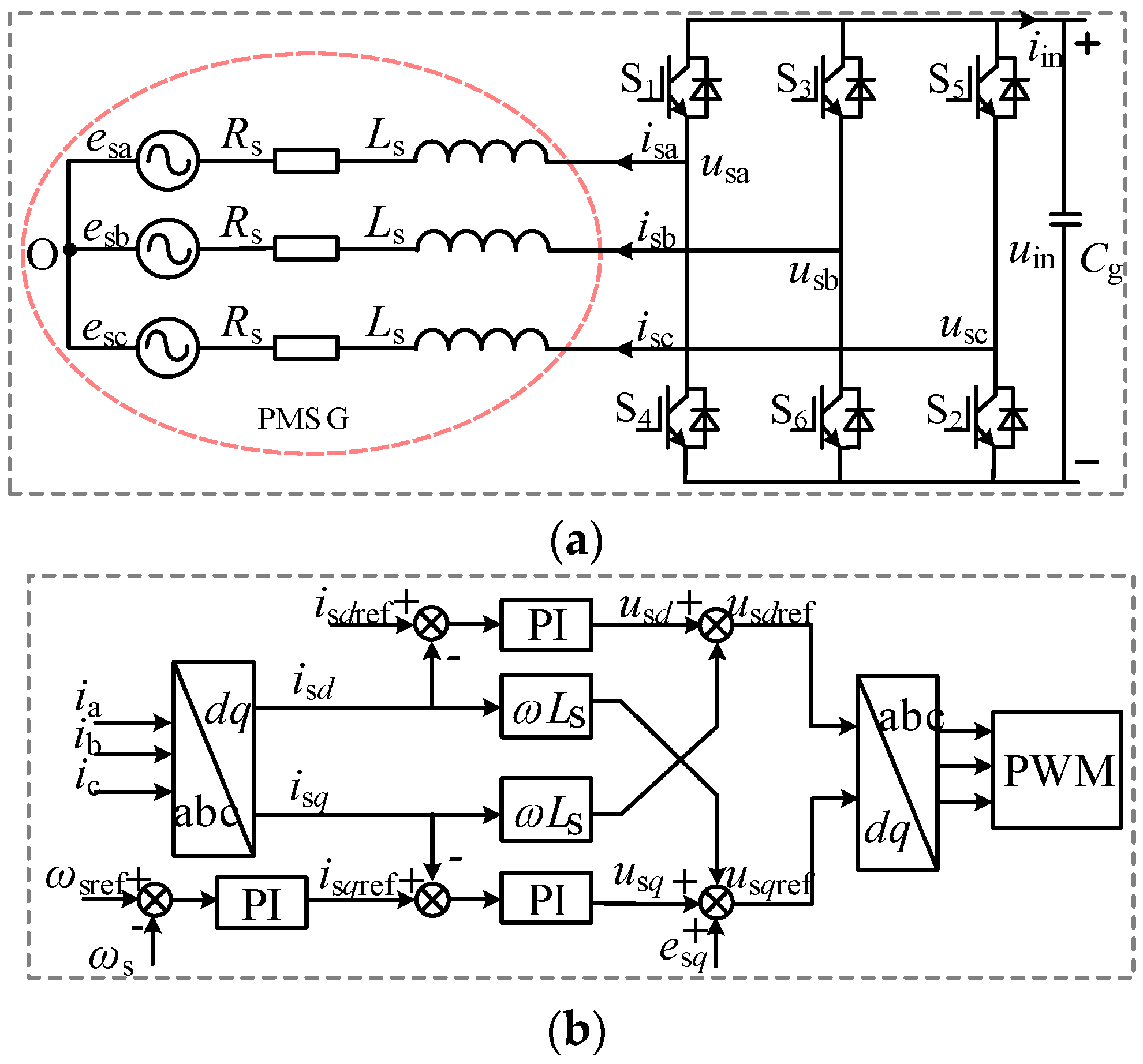
Figure 2a illustrates the topologies of the PMSG and the MSC. The symbols esx, isx, and usx(x = a, b, c) denote the rotor-induced electromotive force, stator current, and converter phase voltage of the PMSG, respectively; Rs represents the stator resistance; Ls denotes the equivalent inductance combining the stator inductor and the external series filter inductor; uin and iin refer to the MSC outlet voltage and current, respectively. The MSC employs a current vector control strategy, setting isd = 0 to regulate the active power output from the DCWT in real time. The difference between the reference rotational speed ωsref and the actual rotational speed ωs is processed by the PI regulator to generate isqref, and the inner-loop current is manipulated by the PI regulator to produce modulation signals usdref and usqref. These signals are modulated to the bridge-arm switching tubes through PWM modulation using the Park transformation, as shown in Figure 2b, to ensure the DCWT operates stably.
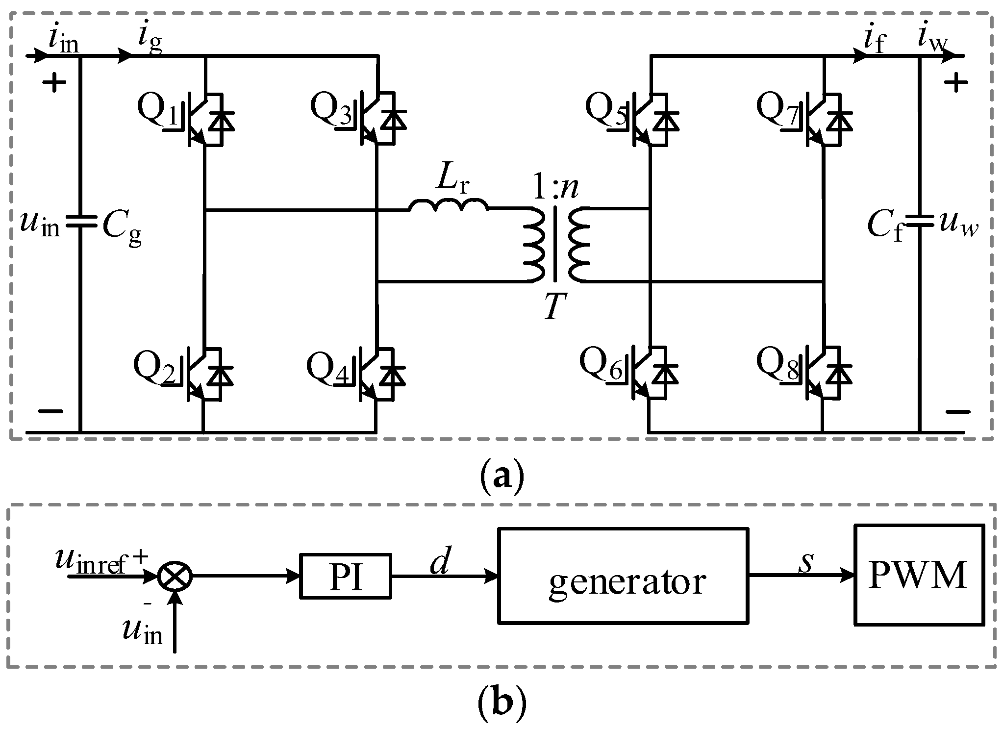
Figure 3 illustrates the topology and control block diagram of the DAB, where Cg and Cf represent the DC bus voltage stabilization capacitors on the input and output sides of the DAB, respectively. The currents on the input and output sides of the DAB’s bridge arm are denoted as ig and if, respectively, while uw and iw signify the outlet voltage and current of the Direct Current Wind Turbine (DCWT). The DAB controller adjusts the voltage command value uinref based on the deviation from the actual voltage uin, as determined by the PI controller’s output, which then alters the duty cycle (d). Modifying d facilitates PWM modulation of the bridge arm switching tube, thus stabilizing the DC bus voltage and enabling maximum power transfer, as depicted in Figure 3b.
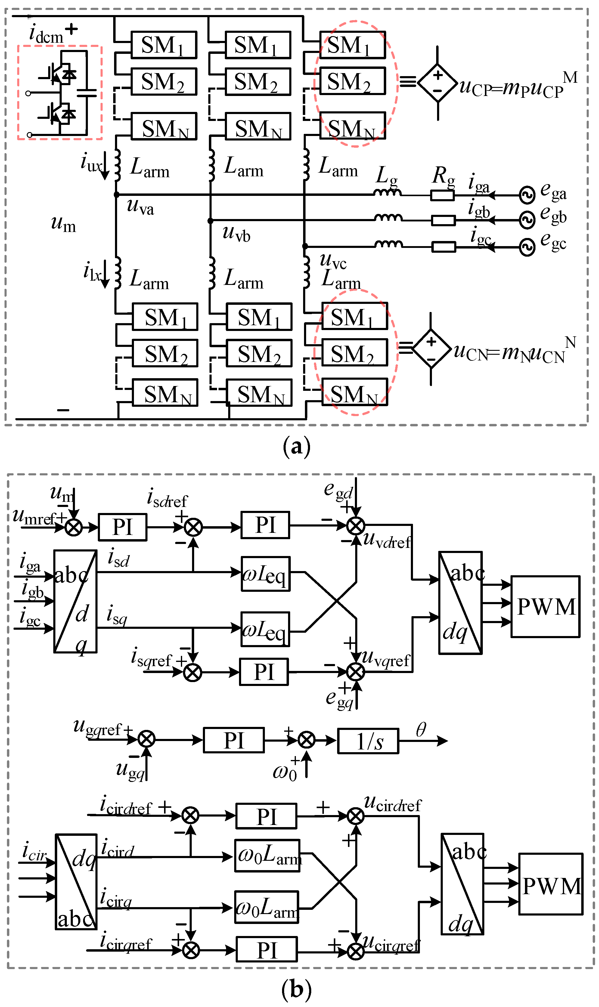
Figure 4a displays the topology of the Modular Multilevel Converter (MMC). The DC voltage and current are denoted as um and idcm, respectively. Rarm and Larm represent the resistance and inductance of the bridge arm, while Rg and Lg indicate the equivalent resistance and inductance on the AC side. The voltages across the upper and lower bridge arms are labeled as uCP and uCN, with mP and mN being the modulation signals for the upper and lower bridge arms, respectively. Furthermore, iux, ilx, igx, uvx, and egx(x = a, b, c) represent the currents through the upper and lower bridge arms, the MMC outlet AC current, and the AC system voltage, respectively.
The control block of the MMC is depicted in Figure 4b. The main controller relays the difference between the command voltage value umref and the actual voltage value um to the PI regulator. This process generates the inner-loop current command value. Subsequently, through PI control, it produces modulation voltage reference values uvdref and uvdref for implementing the PWM modulation of the bridge arm switching tubes. This mechanism ensures stabilization of the DC busbar voltage and efficient power transfer, regulates the system’s reactive power, and guarantees stable system operation. Additionally, the loop current controller, employing double closed-loop control, diminishes the bridge arm loop current component and mitigates fluctuations in the sub-module capacitor voltage.

2.2. Impedance Model

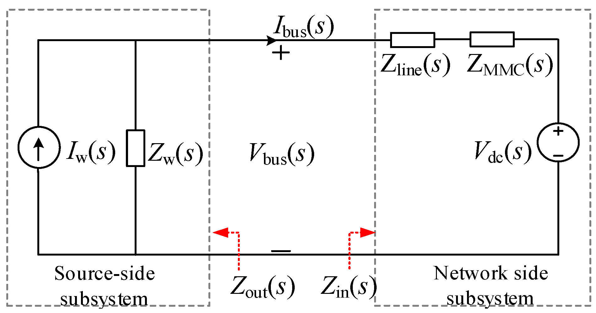
The impedance model serves as the cornerstone for analyzing the small-signal stability of a system, employing Thevenin’s and Norton’s theorems to model the system (as shown in Figure 1) from the outlet of the Direct Current Wind Turbine (DCWT) to the source and network subsystems (illustrated in Figure 5). In this model, ZMMC(s) represents the equivalent impedance of the Modular Multilevel Converter (MMC) and the port on the DC side of the AC system. Zline(s) denotes the impedance of the DC line, while Iw(s) and Vdc(s) symbolize the equivalent controlled DC source and voltage source, respectively. Vbus(s) and Ibus(s) refer to the voltage and current at the system’s Medium Voltage Direct Current (MVDC) bus. The input impedance of the network-side subsystem is given by Zin(s) = ZMMC(s) + Zline(s), and the output impedance of the source-side subsystem is Zout(s) = Zw(s). The expression for the system’s bus voltage, Vbus(s) (s), is derived as follows:
V bus ( s ) = ( V dc ( s ) + I w ( s ) Z in ( s ) ) / ( 1 + Z in ( s ) Z out ( s ) )
According to the Nyquist stability criterion, which leverages the impedance ratio approach as proposed by Middlebrook [5], the stability of the Medium Voltage Direct Current (MVDC) bus voltage hinges on the ratio between Zin(s) and Zout(s), provided that both the source and grid-side subsystems are in a stable state of operation. Thus, the transfer function Tm= Zin(s)/Zout(s) is established. The MVDC bus voltage remains stable if Tm conforms to the Nyquist stability criterion [8,9,10]. The characteristics of Zin(s) and Zout(s) for the subsystem are influenced by the circuit parameters and the parameters of each controller within the system. Building upon the impedance modeling concepts found in the literature [16,17,18,19], this analysis models the subsystem impedance and evaluates the impact of variations in circuit parameters and control parameters on the equivalent impedance characteristics of Zin(s) and Zout(s) ports of the subsystem. It further examines the effects that significantly influence the external impedance characteristics and identifies the predominant factors affecting system stability through analysis of Tm Nyquist curves and time–domain validation.

2.2.1. Source-Side Subsystem Output Impedance Model

The output impedance of the source-side subsystem is modeled by the impedance of the DCWT. Taking into account the dynamic characteristics of the main circuit and the controller within the DCWT, the dynamic equation for the DCWT axis system (see Appendix A Equation (A1)) is linearized to analyze the system’s response when subjected to a small disturbance:
s + ρ π R 2 C p v 3 2 J ω 0 2 + R ω J ω ^ + 3 n p ψ f 2 J i ^ s q = 0
where the letters with ^ denote the amount of small-signal disturbance of the corresponding physical quantity and the same below.
Linearizing the dynamic equation of the main circuit on the machine side of the DCWT (as presented in Appendix A Equation (A2) and depicted in Figure 2a) results in the following:
( s L s + R s ) i ^ s d = e ^ s d + n p L s i s q 0 ω ^ + n p L s ω 0 i ^ s q + u in 0 s ^ d + s d 0 u ^ in ( s L s + R s ) i ^ s q = e ^ s q n p L s i s d 0 ω ^ n p L s ω 0 i ^ s d + u in 0 s ^ q + s q 0 u ^ in
where esd, esq and isd, isq are the d,q-axis components of the stator voltage and current, respectively, and sd, sq are the steady-state values of the duty cycle at the d-axis and q-axis steady-state operating points. np is lar logarithm,ω is the rotational angular velocity of the rotor. And with zero is the steady state value of the variable.
The impedance model of the DCWT is related to its control strategy. Linearizing the dynamic equations (Appendix A Equation (A3)) of the MSC controller (Figure 2b) yields the following:
( i ^ s d ref i ^ s d ) G 1 + n p L s i s q 0 ω ^ + n p L s ω 0 i ^ s q = u in 0 s ^ d G 2 G 3 ω ^ sref + Q 1 ω ^ n p L s ω 0 i ^ s d G 3 i ^ s q = u in 0 s ^ q
where Gx = kpx + kix/s (x = 1, 2, 3), G1 is the d-axis current inner-loop PI parameter; G2 is the q-axis rotational speed outer-loop PI parameter; G3 is the q-current inner-loop PI parameter, and Q1 is the intermediate variable as seen in Appendix A Equation (A5).
Similarly, linearizing the DAB main circuit (Figure 3a) and the controller (Figure 3b) dynamic equations (Appendix A Equation (A4)) produces the following:
s C g u ^ in = 3 2 s d 0 i ^ sd + i sd 0 s ^ d + s q 0 i ^ sq + i sq 0 s ^ q i ^ g s C f u ^ w = i ^ f i ^ w
where D is the steady-state value of the duty cycle; fs is the switching frequency; G4 is the voltage outer-loop PI parameter.
Organize Equations (2)–(5) above into matrix form (Appendix A Equation (A6)):
A wt 1 B wt = X ^ wt / i ^ w
where the coefficient matrix is denoted as Awt, the state variable is denoted as Xwt, and the matrix of coefficients on the right-hand side of the equation is denoted as Bwt, such that Twti =A−1wtBwt. The DCWT output impedance can be written as follows:
Z out ( s ) = T wt 7

2.2.2. Network-Side Subsystem Input Impedance Model

Using the π-type equivalent model for the DC line, the equivalent impedance of the DC transmission line accounts for its minimal distributed capacitance on both ends. Consequently, the capacitance at both ends is incorporated into the capacitance at the interfaces of the DAB and the Modular Multilevel Converter (MMC), resulting in the equivalent impedance of the DC transmission line being calculated without considering the distributed capacitance on both sides:
Z l i n e ( s ) = R l i n e + s L l i n e
Drawing on the modeling ideas from the literature [21], the MMC impedance matrix is derived from Figure 4a,b (Appendix A Equation (A7)):
A MMC 1 B MMC = X ^ MMC / u ^ m
where the coefficient matrix is denoted as AMMC, the state variable is denoted as XMMC, and the coefficient matrix on the right-hand side of the equation is denoted as BMMC, so that TMMCi =A−1MMCBMMC, and the DC side impedance of MMC is obtained as follows:
Z MMC ( s ) = 1 / 3 T MMC 10
From (8) and (10), the following is obtained:
Z in ( s ) = Z MMC ( s ) + Z l i n e ( s )

2.2.3. Model Validation

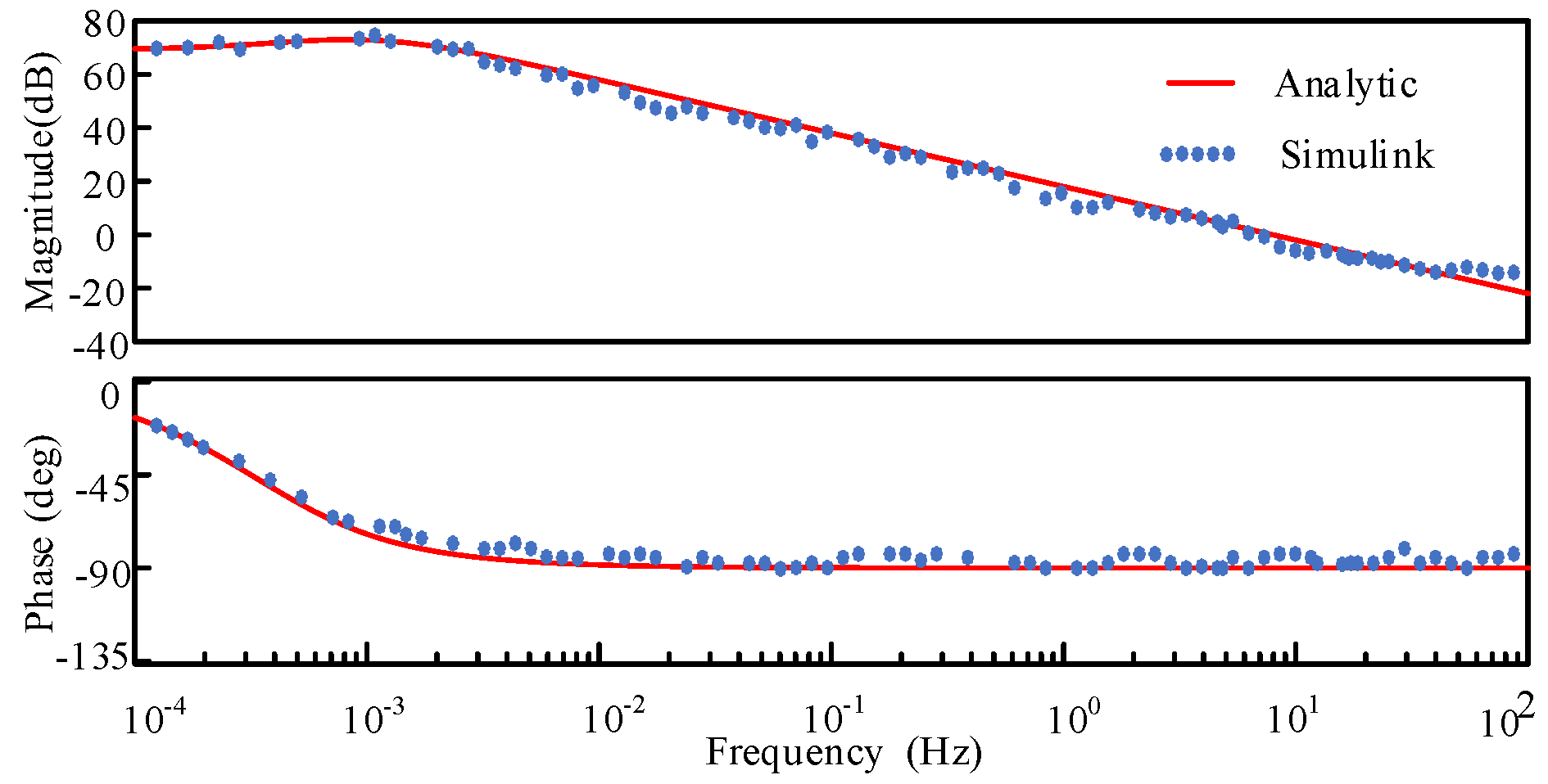
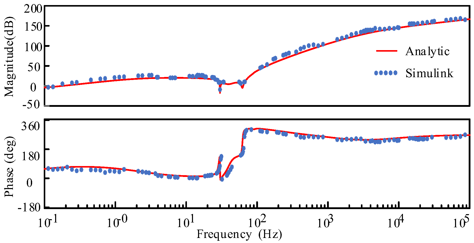
To validate the accuracy of the derived models for the subsystem input and output impedance, this study employs an electromagnetic transient simulation model of the system. A controlled current source is connected in parallel across the DC lines, serving as a perturbation signal (illustrated in Figure 6). By varying the frequencies of the current source, the voltage response signals at corresponding frequencies are measured. This approach enables the determination of the subsystem input and output impedances across different frequencies. The simulation parameters are detailed in Appendix C, within Table A1 and Table A2. The impedance curves derived theoretically, as presented in Bode plots, are in agreement with the impedances obtained from simulation measurements, as shown in Bird’s plots (Figure 7 and Figure 8).

2.3. Impedance Characterization

From the equations for the input and output impedance of the subsystem, it is evident that the stabilization of small disturbances within the system is predominantly influenced by the circuit parameters (Cg, Cf, Rline, Lline) and the gains of control parameters (K1, K2, K3, K4, Ku, Ki, Kcir, Kpll). By analyzing the impedance characteristics related to these system parameters and evaluating their impact on impedance, it is possible to identify the crucial parameters that dictate the system’s stability.

2.3.1. Effect of Circuit Parameters on Subsystem Impedance Characteristics

Figure 9 and Figure 10 present the Bode plots of the subsystem output impedance (Zout) under varying values of MSC and DCWT outlet capacitances (Cg and Cf), respectively. The analysis indicates that within a certain range, both the magnitude and phase of Zout diminish as Cf increases, adversely affecting system stability. Conversely, Cg exerts minimal influence on the Zout of the subsystem.
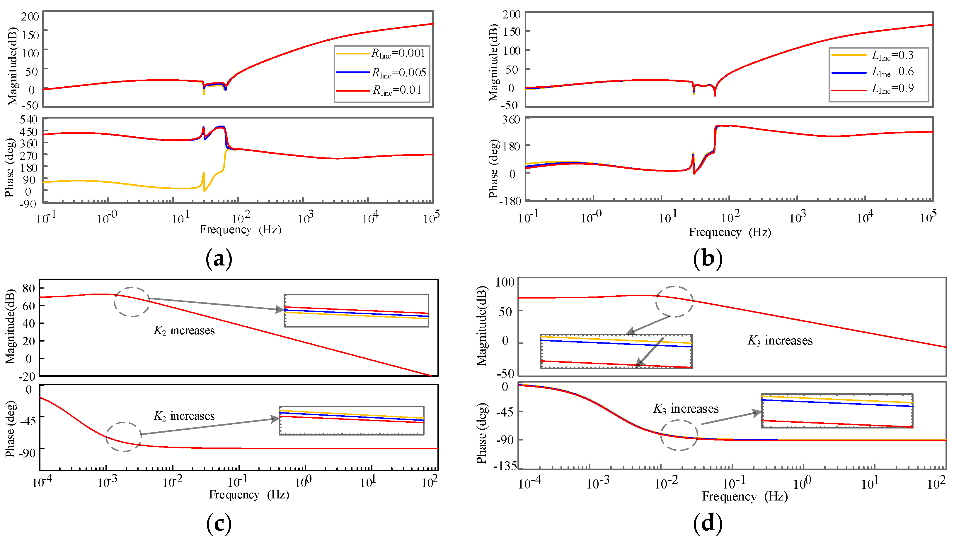
The parameters of DC transmission lines are typically fixed and cannot be easily modified, with their Rline and Lline values being directly proportional to the line’s length, as detailed in Appendix B. Figure A1a,b illustrates the Bode plots of the subsystem input impedance (Zin) when Rline and Lline of the DC transmission line are increased. The analysis indicates that the variations in Zin are minimal when Rline and Lline are increased, demonstrating that their influence on Zin is relatively insignificant.

2.3.2. Effect of Control Parameters on System Impedance Characteristics

To investigate the influence of DCWT control parameters on the output impedance characteristics of the subsystem, the formula incorporating the defined controller gain coefficients Kx (x = 1,2,3,4) is presented as follows:
H ( s ) = K x k p x + k i x / s
Similarly, to examine the impact of the MMC inverter’s control parameters on the input impedance characteristics of the subsystem, Ku, Ki, Kcir, and Kpll are designated as the DC voltage outer-loop gain, inner-loop current gain, circulating current control gain, and phase-locked loop control gain, respectively.
Figure 11, Figure 12 and Figure 13 display the Bode plots for the DAB subsystem output impedance (Zout) across a specified range of increases in the voltage control loop gain K4 and the Bode plot for input impedance (Zin) over a certain range of increases in Ku and Ki. The analysis reveals that as K4 is increased, the amplitude of Zout diminishes, suggesting that elevating K4 adversely affects system stability. Conversely, augmenting Ku and Ki leads to a gradual reduction in the amplitude of Zin, indicating that increasing Ku and Ki promotes system stability. Hence, it is crucial to select suitable K4, Ku, and Ki parameters to maintain the system’s stability margin.
Figure 14, along with Figure A1c,d in the Appendix B, presents the Bode plots for the Zout of the subsystem within the MSC control system, as the d-axis inner-loop control gain (K1), the speed control outer-loop gain (K2), and the q-axis inner-loop gain (K3) are increased. The analysis reveals that the changes in Zout are minimal when K1, K2, and K3 are incremented, suggesting that K1, K2, and K3 exert limited influence on Zout.
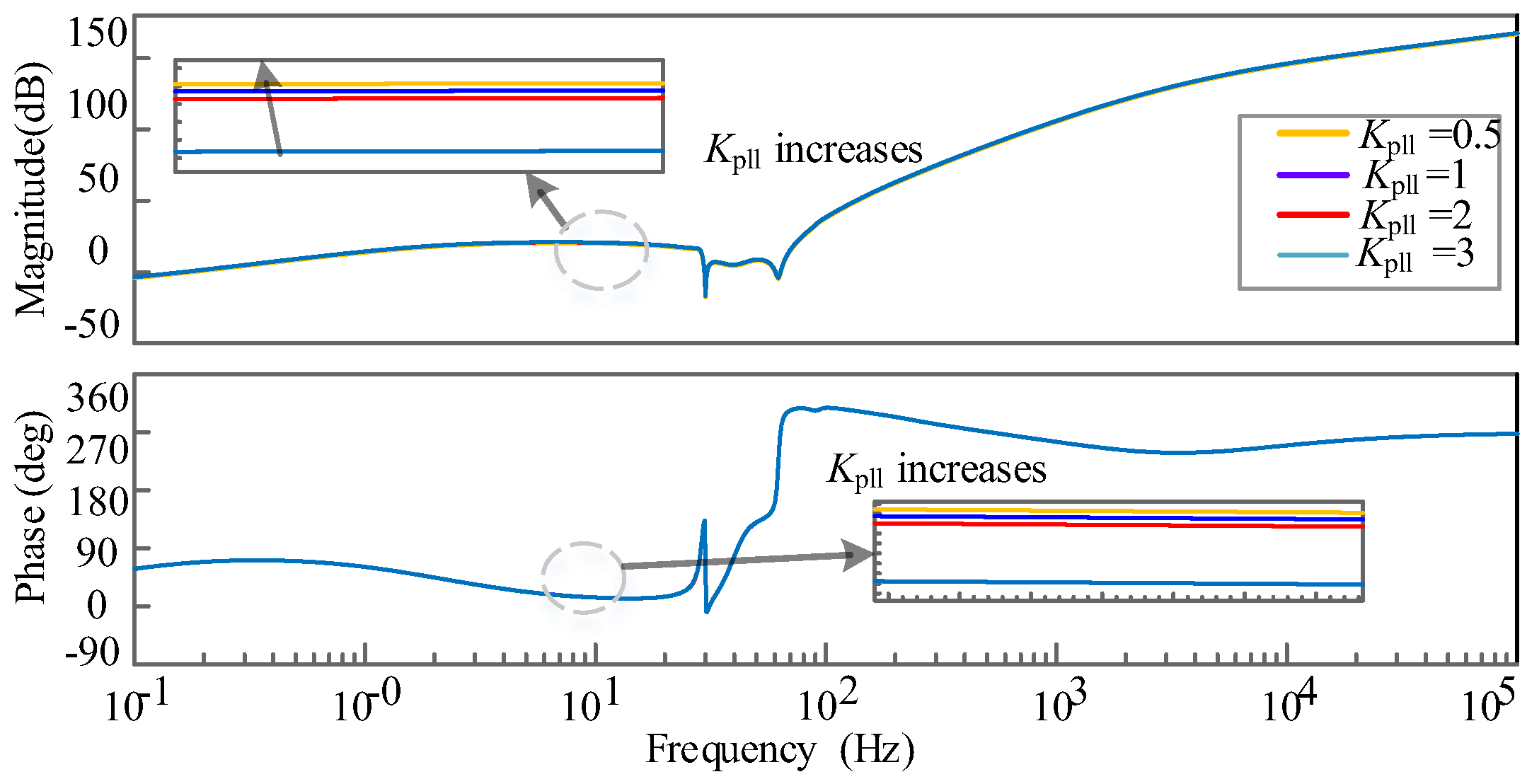
Similarly, Figure 15 and Figure 16 demonstrate that enhancing the Kcir and Kpll has a minimal impact on the amplitude of the Zin of the subsystem.

3. Results

After examining the influence of electrical and control parameters on the external characteristics of the system’s input and output impedances in previous sections, we pinpointed the factors that notably impact the external characteristics of subsystem impedance. This section employs Nyquist plots and time–domain validation to specifically ascertain the dominant parameters that affect system stability.
Figure 17 displays the Nyquist curve of Tm prior to parameter tuning alongside the time–domain simulation of the system. The analysis indicates that the Nyquist curve is well-distanced from the critical point (−1, j0), confirming that the system remains stable.
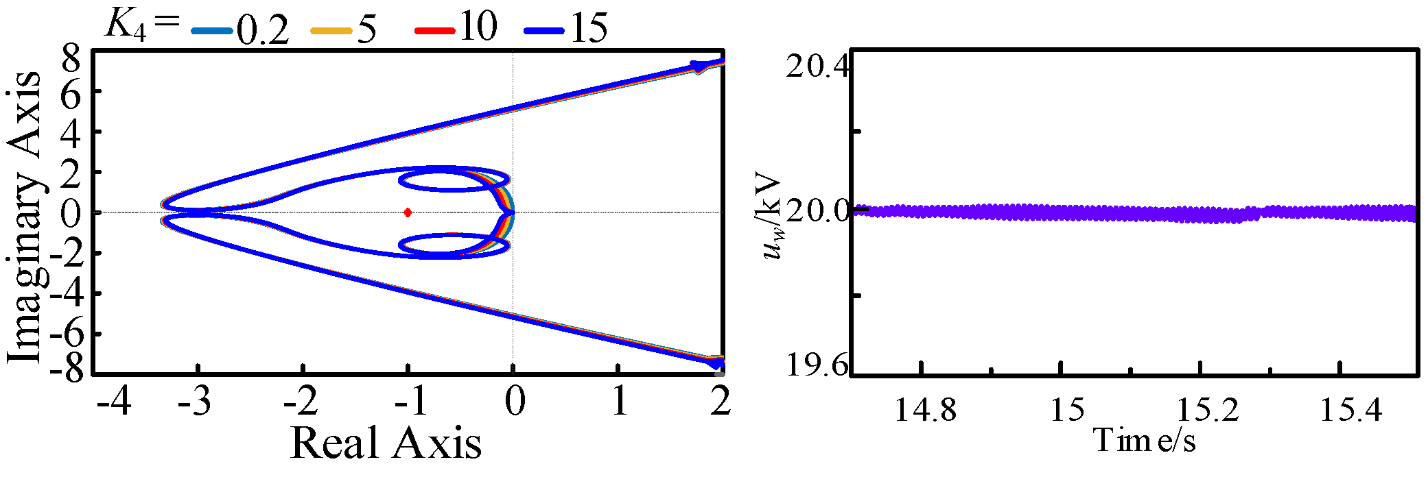
The analysis of Figure 18 and Figure 19 reveals that with an increase in Cf and K4, the Nyquist curve approaches the point (−1, j0), leading to a reduced stability margin of the system. This reduction is not favorable for system stabilization. However, increasing Cf and K4 will not destabilize the system.
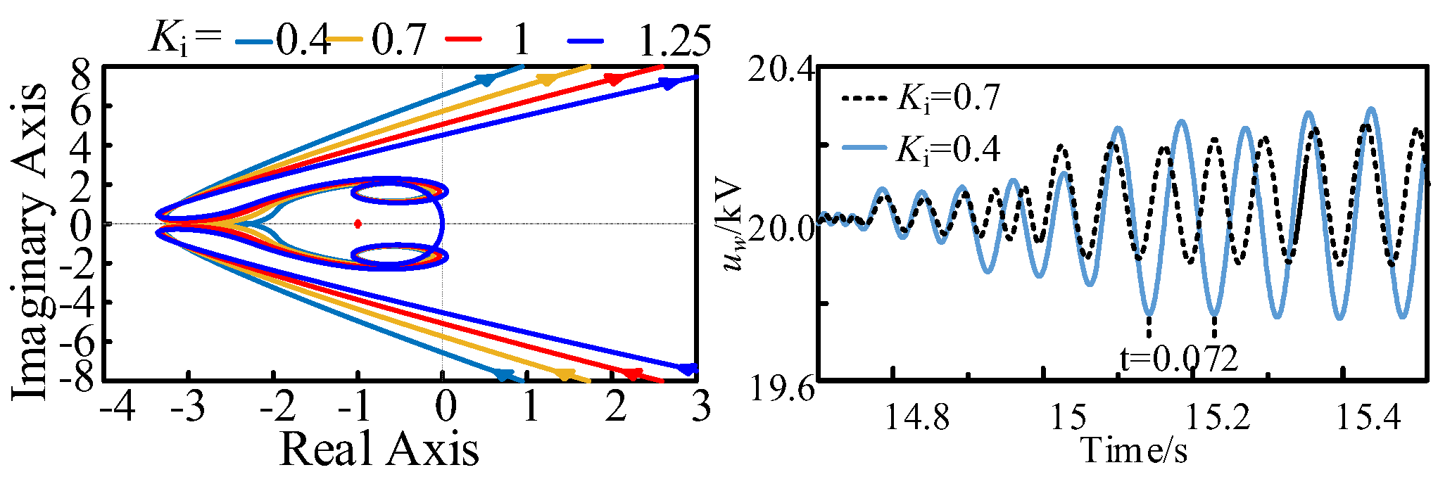
Analyzing Figure 20 and Figure 21 reveals that the system becomes destabilized when Ku = 0.5, 0.75, Ki = 0.7, 0.9 and stabilizes as Ku and Ki increase to Ku = 1, Ki = 1, with the Nyquist curve moving away from the point (−1, j0). Furthermore, as Ku, Ki continue to increase, the stability margin widens, which is beneficial for system stabilization.
Analyzing the impact of system circuit parameters and controller parameters on Tm alongside system time–domain simulations reveals that Cf, K4, Ku, and Ki significantly influence Tm. Increasing Ku, Ki transitions the system from an oscillatory destabilized state to a stable condition. Meanwhile, Cf and K4 do not lead to destabilization, indicating that Ku = 0.75, Ki = 0.7 are crucial factors in stabilizing small perturbations. Furthermore, when Ku = 0.75, Ki = 0.7, the system oscillates at a frequency of 13.89 Hz, with the oscillation amplitude increasing with Ku, signifying that Ku exerts the most significant influence on system stability, as demonstrated in Figure 22.

4. Discussion

(1)
In response to the pronounced mismatch between the source and the network following the integration of large-scale wind power access systems, this study proposes an effective solution for organizing large-scale wind power aggregation and transmission grids. This approach is specifically designed for implementation in the resource-rich regions with developed onshore wind energy in northwestern China. Its primary goal is to fortify the interconnection between the power source and the network, thus improving the operational stability of the power grid. By capitalizing on the inherent benefits of traditional AC aggregation and transmission, combined with AC aggregation and DC transmission within a unified DC network framework, this strategy significantly reduces the need for rectifier inverters, thereby decreasing power losses. Moreover, employing DC transmission across various frequency domain station areas for interconnection leads to a lower short-circuit capacity. Consequently, this method provides an effective solution to overcome challenges related to AC aggregation, such as issues with reactive power transmission and harmonic resonance.
(2)
Leveraging the impedance framework of the OWDCG system, this study aims to identify the primary factors leading to oscillatory instability under small disturbances, with a particular focus on the dynamics involving multi-inverter control coupling. To achieve this, a comprehensive analysis is conducted, encompassing impedance characterization and the identification of dominant parameters. The findings offer a theoretical foundation for improving the stability of the OWDCG in response to minor perturbations. Unlike the stability factor analysis related to conventional wind turbine AC convergence and transmission under small disturbances, this research underscores that the Modular Multilevel Converter (MMC) control parameters within the OWDCG architecture play a crucial role in influencing its oscillatory behavior.
(3)
The stability analysis of small perturbations in the OWDCG system and the identification of dominant factors discussed in this paper hold significant relevance for the design and optimization of controllers in practical engineering applications of fully integrated DC wind power generation systems. This analysis plays a pivotal role in ensuring the system’s safe and stable operation. It is important to note that this paper does not account for the impacts of more complex topologies and varied control strategies. Leveraging the findings from this study, future research could further investigate stability across multiple topologies and control strategies to pinpoint the dominant factors affecting system stability. Moreover, future studies might also examine the system’s stability characteristics across different power regions, thereby expanding our understanding of its operational dynamics.

5. Conclusions

In this paper, the subsystem equivalent impedance model of the OWDCG is established, the effects of the system circuit parameters and controller parameters on the subsystem input and output impedance and the system small perturbation stabilization are analyzed using Bode plots, Nyquist plots, and time–domain simulation, and the following conclusions are obtained:
(1)
Increasing the DCWT outlet capacitance Cf and DAB control gain K4 is detrimental to the system small disturbance stabilization, and increasing the MMC inverter DC voltage control loop gain Ku and current inner-loop gain Ki is beneficial to the system stabilization. Increasing the MSC controller gains K1K3, DC transmission line resistance Rline, inductance Lline, loop current control gain Kcir, and phase-locked loop control gain Kpll have less effect on the system’s small disturbance stabilization.
(2)
The degree of influence of different parameters on the impedance characteristics of subsystems and the small disturbance stability of the system is revealed; Ku and Ki are the dominant factors of the small disturbance stability, and Ku has the greatest influence on the optimal design of the system control parameters to provide a theoretical basis for the stable operation of the onshore wind power all-direct current power generation system, which has a guiding significance in engineering.
In this paper, the small perturbation stability analysis takes an OWDCG as an example; the OWDCG still has economic advantages in large-scale wind farms and will be combined with the technical specifications and requirements of large-scale wind farms for pooling and is sent out to analyze the dominant parameters of the small perturbation stability of the OWDCG with multiple DC wind turbines and different topological structures.

Author Contributions

Conceptualization, T.W.; methodology, T.W. and F.L.; formal analysis, T.W. and G.J.; writing—original draft preparation, T.W.; writing—review and editing, T.W.; supervision, C.Y.; funding acquisition, F.L. All authors have read and agreed to the published version of the manuscript.

Funding

This research was funded by the National Key Research and Development Program of China under Grant 2021YFB1507000.

Data Availability Statement

Data are unavailable due to privacy reasons.

Acknowledgments

I am very grateful to the National Key Research and Development Program of China for supporting me in writing this article and my research in this field. I will continue to perform in-depth research.

Conflicts of Interest

The authors declare no conflicts of interest.

Appendix A

Dynamic equations of the axial system:
J d ω d t = T M T e R w ω T M = 1 2 ρ S C p v 3 / ω T e = 3 2 n p ψ f i s q
PMSG and MSC main circuit dynamic equations:
e s d = R s i s d L s d i s d d t + ω s L s i s q + s d u in e s q = R s i s q L s d i s q d t ω s L s i s d + s q u in
MSC controller dynamic equations:
( i s d ref i s d ) G 1 + ω s L s i s q = u s d ( ( ω sref ω s ) G 2 i s q ) G 3 ω s L s i s d + ω s ψ f = u s q
DAB main circuit and controller dynamic equations:
C g d u in d t = 3 2 s d i s d + s q i s q i g C f d u w d t = i f i w i g = d ( 1 d ) u w 2 n f s L r ,   i f = d ( 1 d ) u in 2 n f s L r
Intermediate variables:
Q 1 = ( n p G 2 G 3 n p L s i s d 0 + n p ψ f )
s + ρ π R 2 C p v 3 2 J ω 0 2 + R ω J 0 3 n p ψ f 2 J 0 0 0 0 n p i s q 0 s + R s L s n p ω 0 u in 0 L s 0 s d 0 L s 0 n p ψ f L s n p ω 0 s + R s L s 0 u in 0 L s s q 0 L s 0 n p i s q 0 L s G 1 n p ω 0 L s u in 0 0 0 0 n p G 2 G 3 + n p ψ f n p ω 0 L s G 3 0 u in 0 0 0 3 s d 0 2 3 s q 0 2 0 3 s q 0 2 s C g 1 2 D G 4 u w 0 2 n f s L r D 1 D 2 n f s L r 0 0 0 0 0 D 1 D 1 2 D G 4 u in 0 2 n f s L r s C f A wt w ^ i ^ s d i ^ s q s ^ d s ^ q u ^ i n u ^ w X wt = 0 0 0 0 0 0 1 B wt i ^ w
G ucp21 0 0 G ucp1 0 0 G idiff21 G idiff22 G i 1 G i 2 G idiff01 G idiff02 0 0 0 0 0 0 0 G ucp22 0 G ucp2 G ucp01 G ucp02 G idiff23 G idiff24 G i 3 0 G idiff03 0 0 0 0 0 0 G m 21 G ucp23 G ucp24 G ucp3 G ucp4 G ucp03 G ucp04 0 0 G i 4 0 0 G idiff04 G uv1 0 G m 1 0 0 0 0 G ucp25 G ucp26 0 G ucp5 G ucp6 0 G ucp05 G ucp06 0 G idiff25 G idff26 G iuv G i 5 G i 6 0 G idiff05 G idff06 G uv2 0 0 G muv G m 3 0 G m 2uv 0 G m 22 A MMC u ^ CP2 M u ^ CP M u ^ CP0 M i ^ diff2 i ^ g i ^ diff0 u ^ v m ^ m ^ 2 X ^ MMC = 0 0 0 0 0 G idiff07 0 G mudc   0 B MMC u ^ m

Appendix B

Figure A1. (a) Input impedance of the subsystem when Rline changes; (b) input impedance of the subsystem when Lline changes; (c) output impedance of the subsystem when K2 changes; (d) output impedance of the subsystem when K3 changes.
Energies 17 01459 g0a1

Appendix C

Table A1. DC wind power turbine parameters.
ModuleParametersValue
Wind power turbineWind power turbine radius R/m58
Air density p/kg·m−31.225
Self-damping factor Rm0.002
D-PMSGPolar logarithm np49
Stator equivalent resistor Rs/Ω0.001
Stator equivalent inductance Ls/mH12.8
Rotor magnetic chain Ψf/Wb0.0417
DC sideMSC outlet capacitance Cg/mF12
MSC control systemRotation speed reference Rref/p.u.0.8
Stator current d-axis reference isdref0
Rotation speed outer-loop factor (kp2, ki2)0.4, 0.4
q-axis current inner-loop factor (kp3, ki3)1, 0.2
d-axis current inner-loop factor (kp1, ki1)1, 0.2
MSDCT control systemVoltage outer-loop factor (kp4, ki4)0.1, 0.075
DCWT outletDCWT outlet capacitance Cf/mF20
Table A2. MMC inverter parameters.
ModuleParametersValue
InverterSubmodule number20
Bridge resistance Rarm0
Bridge inductance Larm/mH20
Bridge capacitance Carm/mF15
Voltage control systemDCWT outlet voltage reference uwref/p.u.1
q-axis current inner-loop reference iqref/p.u.0
Voltage outer-loop factor (kpu, kiu)0.5, 3
Current inner-loop factor (kpi, kii)30, 300
Circulation suppress controlq-axis circulation inner-loop reference0
d-axis circulation inner-loop reference0
q-axis circulation inner-loop factor (kpcir, kicir)1, 2400
d-axis circulation inner-loop factor (kpcir, kicir)1, 2400
Phase-locked loop controlPhase-locked loop factor (kpllp, kplli)0.1, 100

References

  1. Jiang, L.; Chi, Y.; Qin, H.; Pei, Z.; Li, Q.; Liu, M.; Bai, J.; Wang, W.; Feng, S.; Kong, W.; et al. Wind Energy in China. IEEE Power Energy Mag. 2011, 9, 36–46. [Google Scholar] [CrossRef]
  2. An, F.; Zhao, B.; Cui, B.; Bai, R. Multi-functional DC collector for future ALL-DC offshore wind power system: Concept, scheme, and implement. IEEE Trans. Ind. Electron. 2022, 69, 8134–8145. [Google Scholar] [CrossRef]
  3. Liu, W.; Ge, R.; Li, H.; Ge, J. Impact of Large-Scale Wind Power Integration on Small Signal Stability Based on Stability Region Boundary. Sustainability 2014, 6, 7921–7944. [Google Scholar] [CrossRef]
  4. Liu, H.; Xie, X.; Li, Y.; Liu, H.; Hu, Y. A small-signal impedance method for analyzing the SSR of series-compensated DFIG-based wind farms. In Proceedings of the 2015 IEEE Power & Energy Society General Meeting, Denver, CO, USA, 26–30 July 2015; pp. 1–5. [Google Scholar] [CrossRef]
  5. Salehi, F.; Matsuo, I.B.M.; Brahman, A.; Tabrizi, M.A.; Lee, W.J. Sub-Synchronous Control Interaction Detection: A Real-Time Application. IEEE Trans. Power Deliv. 2020, 35, 106–116. [Google Scholar] [CrossRef]
  6. Adams, J.; Carter, C.; Huang, S.-H. ERCOT experience with Sub-synchronous Control Interaction and proposed remediation. In Proceedings of the PES T&D 2012, Orlando, FL, USA, 7–10 May 2012; pp. 1–5. [Google Scholar] [CrossRef]
  7. Song, Y.; Blaabjerg, F. Analysis of the Behavior of Undamped and Unstable High-Frequency Resonance in a DFIG System. IEEE Trans. Power Electron. 2017, 32, 9105–9116. [Google Scholar] [CrossRef]
  8. Song, Y.; Wang, X.; Blaabjerg, F. Impedance-Based High-Frequency Resonance Analysis of DFIG System in Weak Grids. IEEE Trans. Power Electron. 2017, 32, 3536–3548. [Google Scholar] [CrossRef]
  9. Song, Y.; Blaabjerg, F. Overview of DFIG-Based Wind Power System Resonances Under Weak Networks. IEEE Trans. Power Electron. 2017, 32, 4370–4394. [Google Scholar] [CrossRef]
  10. Xu, Y.; Nian, H.; Hu, B.; Sun, D. Impedance Modeling and Stability Analysis of VSG Controlled Type-IV Wind Turbine System. IEEE Trans. Energy Convers. 2021, 36, 3438–3448. [Google Scholar] [CrossRef]
  11. Dong, W.; Du, W.; Xie, X.; Wang, H.F. An Approximate Aggregated Impedance Model of a Grid-Connected Wind Farm for the Study of Small-Signal Stability. IEEE Trans. Power Syst. 2022, 37, 3847–3861. [Google Scholar] [CrossRef]
  12. Li, M.; Zhang, X.; Guo, Z.; Wang, J.; Wang, Y.; Lib, F.; Zhao, W. The Control Strategy for the Grid-Connected Inverter Through Impedance Reshaping in q-Axis and its Stability Analysis Under a Weak Grid. IEEE J. Emerg. Sel. Top. Power Electron. 2021, 9, 3229–3242. [Google Scholar] [CrossRef]
  13. Nian, H.; Hu, B.; Xu, Y.; Wu, C.; Chen, L.; Blaabjerg, F. Analysis and Reshaping on Impedance Characteristic of DFIG System based on Symmetrical PLL. IEEE Trans. Power Electron. 2020, 35, 11720–11730. [Google Scholar] [CrossRef]
  14. Liu, J.; Yao, W.; Wen, J.; Fang, J.; Jiang, L.; He, H.; Cheng, S. Impact of Power Grid Strength and PLL Parameters on Stability of Grid-Connected DFIG Wind Farm. IEEE Trans. Sustain. Energy 2020, 11, 545–557. [Google Scholar] [CrossRef]
  15. Ma, R.; Han, Y.; Pan, W. Variable-Gain Super-Twisting Sliding Mode Damping Control of Series-Compensated DFIG-Based Wind Power System for SSCI Mitigation. Energies 2021, 14, 382. [Google Scholar] [CrossRef]
  16. Wu, H.; Wang, X. Passivity-Based Dual-Loop Vector Voltage and Current Control for Grid-Forming VSCs. IEEE Trans. Power Electron. 2021, 36, 8647–8652. [Google Scholar] [CrossRef]
  17. Ji, K.; Pang, H.; Liu, S.; Tang, G. Impedance Analysis Considering Unstable Subsystem Poles for MMC-HVDC-based Wind Farm Integration System. CSEE J. Power Energy Syst. 2022, 8, 634–639. [Google Scholar] [CrossRef]
  18. Ji, K.; Tang, G.; Pang, H.; Yang, J. Impedance Modeling and Analysis of MMC-HVDC for Offshore Wind Farm Integration. IEEE Trans. Power Deliv. 2020, 35, 1488–1501. [Google Scholar] [CrossRef]
  19. Wen, B.; Boroyevich, D.; Burgos, R.; Mattavelli, P.; Shen, Z. Analysis of D-Q Small-Signal Impedance of Grid-Tied Inverters. IEEE Trans. Power Electron. 2016, 31, 675–687. [Google Scholar] [CrossRef]
  20. Wang, C.; Pan, D.; Wang, X.; He, Y.; Zhang, H.; Ruan, X.; Chen, X. A General Graphical Method for Filter-Based Active Damping: Evaluation, Exploration, and Design. IEEE J. Emerg. Sel. Top. Power Electron. 2023, 11, 2683–2696. [Google Scholar] [CrossRef]
  21. Lin, Z.; Ruan, X.; Zhang, H.; Wu, L. A Generalized Real-Time Computation Method with Dual-Sampling Mode to Eliminate the Computation Delay in Digitally Controlled Inverters. IEEE Trans. Power Electron. 2022, 37, 5186–5195. [Google Scholar] [CrossRef]
  22. Hans, F.; Schumacher, W.; Chou, S.-F.; Wang, X. Passivation of Current-Controlled Grid-Connected VSCs Using Passivity Indices. IEEE Trans. Ind. Electron. 2019, 66, 8971–8980. [Google Scholar] [CrossRef]
  23. Ma, H.T.; Brogan, P.B.; Jensen, K.H.; Nelson, R.J. Sub-Synchronous Control Interaction studies between full-converter wind turbines and series-compensated AC transmission lines. In Proceedings of the 2012 IEEE Power and Energy Society General Meeting, San Diego, CA, USA, 22–26 July 2012; pp. 1–5. [Google Scholar] [CrossRef]
  24. Mohammadpour, H.A.; Islam, M.M.; Coats, D.; Santi, E.; Shin, Y.-J. Sub-synchronous resonance mitigation in wind farms using a gate-controlled series capacitor. In Proceedings of the 2013 4th IEEE International Symposium on Power Electronics for Distributed Generation Systems (PEDG), Rogers, AR, USA, 8–11 July 2013; pp. 1–6. [Google Scholar] [CrossRef]
  25. Lyu, J.; Cai, X.; Molinas, M. Optimal Design of Controller Parameters for Improving the Stability of MMC-HVDC for Wind Farm Integration. IEEE J. Emerg. Sel. Top. Power Electron. 2018, 6, 40–53. [Google Scholar] [CrossRef]
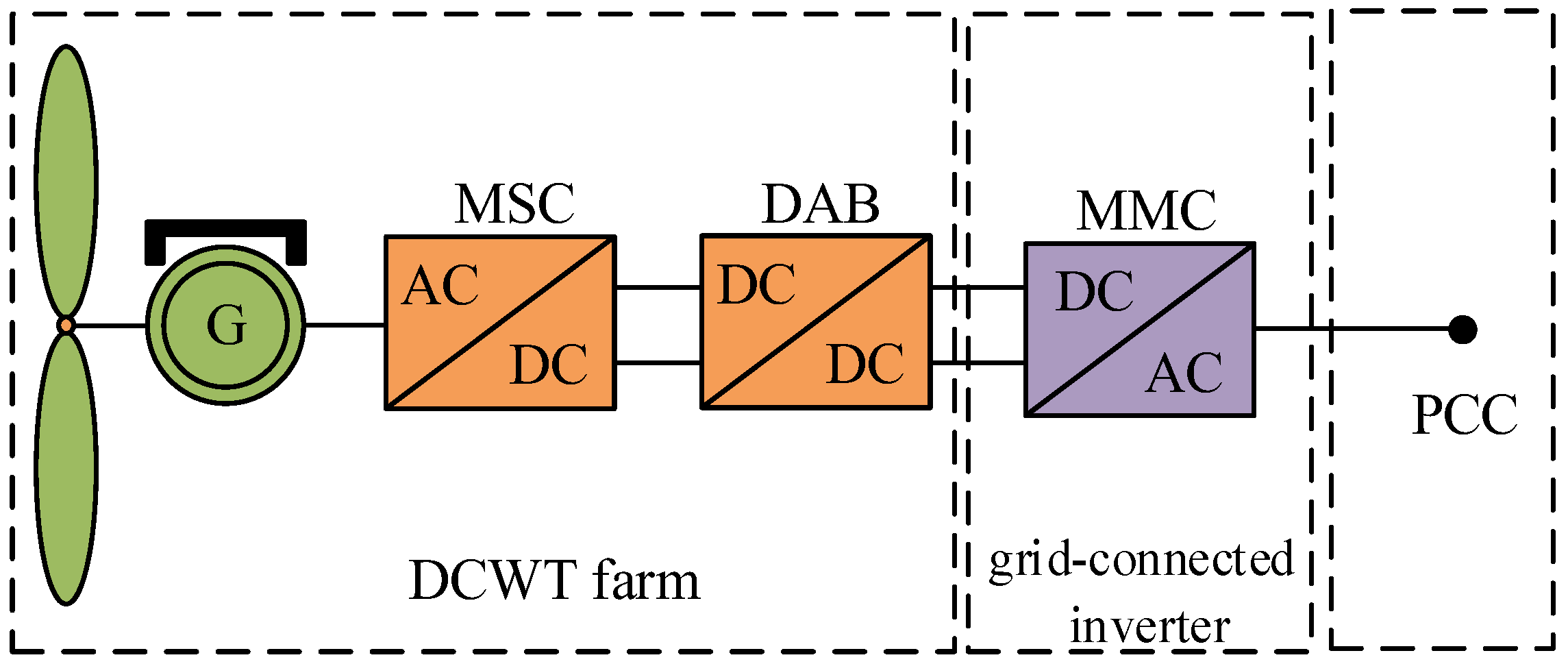
Figure 1. Topology of OWDCG.
Energies 17 01459 g001
Figure 2. Topology and control block of PSMG and MSC. (a) PMSG and MSC topologies; (b) Block diagram of the MSC control system.
Energies 17 01459 g002
Figure 3. Topology and control block of PSMG and MSC. (a) DAB topology map; (b) Block diagram of the DAB control system.
Energies 17 01459 g003
Figure 4. Topology and control block of MMC. (a) MMC topology diagram; (b) Block of the MMC control system.
Energies 17 01459 g004
Figure 5. Impedance equivalent circuit of OWDCG.
Energies 17 01459 g005
Figure 6. Impedance measurement of current source disturbance injection method.
Energies 17 01459 g006
Figure 7. Bode diagram and theoretical bode diagram of the subsystem output impedance measurement.
Energies 17 01459 g007
Figure 8. Bode diagram and theoretical bode diagram of the subsystem input impedance measurement.
Energies 17 01459 g008
Figure 9. Output impedance of the subsystem when Cg takes different values.
Energies 17 01459 g009
Figure 10. Output impedance of the subsystem when Cf takes different values.
Energies 17 01459 g010
Figure 11. The output impedance of the subsystem when K4 changes.
Energies 17 01459 g011
Figure 12. Input impedance of the subsystem when Ku changes.
Energies 17 01459 g012
Figure 13. Input impedance of the subsystem when Ki changes.
Energies 17 01459 g013
Figure 14. The input impedance of the subsystem when K1 changes.
Energies 17 01459 g014
Figure 15. Input impedance of the subsystem when Kcir changes.
Energies 17 01459 g015
Figure 16. Input impedance of subsystem when Kpll changes.
Energies 17 01459 g016
Figure 17. The Nyquist curve of Tm and system time–domain simulation.
Energies 17 01459 g017
Figure 18. The Nyquist curve of Tm as Cf increases and system time–domain simulation.
Energies 17 01459 g018
Figure 19. Nyquist curve of Tm as K4 changes and system time–domain simulation.
Energies 17 01459 g019
Figure 20. The Nyquist curve of Tm as Ku changes and system time–domain simulation.
Energies 17 01459 g020
Figure 21. The Nyquist curve of Tm as Ki changes and system time–domain simulation.
Energies 17 01459 g021
Figure 22. System time–domain simulation as Ki, Ku increase.
Energies 17 01459 g022
Disclaimer/Publisher’s Note: The statements, opinions and data contained in all publications are solely those of the individual author(s) and contributor(s) and not of MDPI and/or the editor(s). MDPI and/or the editor(s) disclaim responsibility for any injury to people or property resulting from any ideas, methods, instructions or products referred to in the content.