Review

Interrelationship of Electric Double Layer Theory and Microfluidic Microbial Fuel Cells: A Review of Theoretical Foundations and Implications for Performance

by
Mumuni Amadu
and
Adango Miadonye
*
School of Science and Technology, Cape Breton University, Sydney, NS B1M 1A2, Canada
*
Author to whom correspondence should be addressed.
Energies 2024, 17(6), 1472; https://doi.org/10.3390/en17061472
Submission received: 2 January 2024 / Revised: 20 February 2024 / Accepted: 27 February 2024 / Published: 19 March 2024
(This article belongs to the Section A: Sustainable Energy)

Abstract

:
Microbial fuel cells and their related microfluidic systems have emerged as promising greener energy alternatives for the exploitation of avenues related to combined power and wastewater treatment operations. Moreover, the potential for their application in biosensing technology is large. However, while the fundamental principles of science that govern the design and operation of microbial fuel cells (MFCs) and microfluidic microbial fuel cells (MMFCs) are similar to those found in colloid science, the literature shows that current research lacks sufficient reference to the electrostatic and electrokinetic aspects, focusing mostly on aspects related to the architecture, design, anodes, microbial growth and metabolism, and electron transfer mechanisms. In this regard, research is yet to consider MFCs and MMFCs in the context of electrostatic and electrokinetic aspects. In this extensive review, we show, for the first time, the interrelationship of MFCs and MMFCs with electric double layer theory. Consequently, we show how the analytical solution to the mean field Poisson–Boltzmann theory relates to these systems. Moreover, we show the interrelationship between MFC and MMFCs’ performance and the electric double layer and the associated electrostatic and electrokinetic phenomena. This extensive review will likely motivate research in this direction.

1. Introduction

Miniaturization technology has paved the way for the integration of sensors that can monitor and translate observed conditions, such as light levels, acceleration, pressure, or temperature, into a signal at the micro level. The signal can then be transmitted and processed through a system or stored as data [1]. Motivated by this technology, MFCs can be classified by their device size as macro, meso, and micro [2]. In this regard, a microfluidic microbial fuel cell (MFC) is defined as a miniaturized MFC with a total cell volume in the range of 1–200 μL [3]. For such systems, a membraneless microfluidic microbial fuel cell, evolving from a microfluidic microbial fuel cell (MMFC), utilizes colaminar flow to separate anolyte and catholyte streams based on a chosen electrode system. The colaminar flow [4] of the two streams inside the microfluidic channel is the impetus for the enhanced diffusion and transfer of protons from the anode to the cathode. In the microfluidic literature, several studies have been conducted to advance knowledge of its design, construction, and performance. For instance, Ye et al. (2013) [4] have demonstrated that the membraneless MMFC (MMMFC) performance initially increases and then decreases with an increasing influent chemical oxygen demand concentration and anolyte flow rate, while reporting a peak power density of ±618 mWm−2. The highest-performing membraneless microfluidic microbial fuel cell (MFC) to date has been presented by Amirdehi et al. (2020) [5]. The system consists of a strictly anaerobic environment and robust graphite electrodes with optimized placement that prevents cross-contamination between electrode compartments [5]. Uria et al. (2017) [6] found that direct electron transfer MFCs showed the best performance, while concluding that biofilms are the major contributors to current production in such systems. The work of Rizvandi and Yesilyurt (2019) [7] considers aspects of hydrodynamics based on the classical Navier–Stokes equation, mass transfer formulations based on Fick’s law [8], and the kinetics of oxidation at the anode.
The literature shows that there are at least 20 different membranes or separators that have been proposed and evaluated for MFCs, based on concepts ranging from salt bridges to advanced synthetic polymer-based membranes [9]. In this regard, Ramirez-Nava et al. (2021) [10] have carried out a critical review of the state-of-the-art membranes and separators used in MFCs, covering such areas as membrane functions in MFCs, the most used membranes, membranes’ cost and efficiency, and membraneless MFCs. For MMMFCs, which use an anolyte and catholyte in the microfluidic channel to enhance the performance, the existence of the electric double layer is important, where pH-dependent surface charging is applicable. In this regard, the electric double layer is a region existing at the interface between an aqueous medium and a solid surface that is assumed to consist of two oppositely charged layers, such as a layer of negative ions adsorbed on colloidal particles that attracts a layer of positive ions in the surrounding electrolytic solution. Moreover, organic matter on which electroactive bacteria rely on for metabolism in such systems can be found in wastewater fuel carriers. Therefore, the hydrodynamics of these channels will be controlled by the electric double layer. To the best of our knowledge, no extensive review has so far been devoted to the relationship between the electric double layer and the hydrodynamics of MFCs. Herein, we have reviewed extensively the theoretical foundations of the electric double layer, and we have shown their interrelationships with MFCs. Saline wastewaters are generated by various industries, including the chemical, pharmaceutical, agricultural, and aquacultural industries [11,12,13,14]. Therefore, for the application of saline wastewater fuel carriers in MFC systems, the use of the Debye–Huckle approximation [11] of the mean field Poisson–Boltzmann equation is possible. Our theoretical review is based on the analytical solution of the linearized approximation of the Poisson–Boltzmann equation [15,16,17,18]. To account for the electroviscous effect in the hydrodynamics associated with the electric double layer, the analytical solution to the classical Navier–Stokes equation with the electric body force is also considered. Moreover, considering the role of fibrous microfluidic systems in microfluidic devices, we have extended the analytical solution to the case wherein the anolyte and catholyte channels of an MMMFC are fibrous. We have also discussed the relationship between the theoretical foundation and MMMFC performance related to the total flow rate, the pH of wastewater fuel carriers, and the electrostatics based on surface charge density and potential models. Consequently, the significance of our extensive review work lies in the intimate relationship between MFCs and the fundamental theory underlying the electric double layer theory as found in the colloidal sciences [19,20,21]. Moreover, with this intimate relationship, it can be hypothesized that, considering the environmental chemistry of organically loaded aqueous solutions, such as wastewater that is characterized by a specific pH and salinity, the hydrodynamics of MMFCs will be governed by the electric double layer as found in unrelated microfluid systems. Our review sheds light on this interrelationship.

2. Review Background

2.1. Microbial Fuel Cells

2.1.1. Architecture

A microbial fuel cell (MFC) is a type of biochemical system wherein electroactive bacteria, acting as a biocatalyst, convert the chemical energy stored in organic matter into electrical energy [22,23]. The bioelectrochemical processes involve the microbial oxidation of organic matter (electron donor) in an anodic chamber and electron acceptance in a cathodic chamber [24]. In this process, the anode stream can contain various types of waste (like food waste, soil and sediments, household waste, agricultural waste streams, and municipal wastewater streams) that can be used as a substrate [25,26]. Figure 1 shows a typical schematic of a microbial fuel cell, while Figure 2 shows the feasibility of a microbial fuel cell using mammalian urine as an energy stream for the bioelectrochemical process. In Figure 1, the protons released from microbial metabolic processes are transferred to the electron acceptor via a proton exchange membrane, while electrons are conducted through the anodic conductor to the cathode through an external circuit.
Akin to conventional chemical fuel cells, the anode and cathode electrodes are fundamental components of MFCs. For their successful integration into the system, biocompatibility, electron conductivity, porosity, low-cost design, recyclability, and scalability are the fundamental requirements. Moreover, a high specific surface area, corrosion resistance, and high mechanical strength are additional requirements [29].
The literature shows that the suitability of several electrode materials has been tested to date [29,30,31,32]. In line with the objective of achieving cost-effectiveness and sustainability in microbial fuel cell design and energy production, nickel, stainless steel, brass, and graphite have been used to explore energy production in double-chamber microbial fuel cells (Hamed et al., 2020) [32]. The mentioned study reported the differences in performance for each electrode material, with nickel and graphite giving the highest efficiency. In these systems, yeast and glucose were used as the microbes and substrate, respectively. Moreover, carbon cloth, carbon paper, carbon felt, and purpose-built advanced materials, such as dimensional carbon-based and metal–carbon composite materials, have also been reported [29].

2.1.2. Membraneless Microfluidic Microbial Fuel Cells (MMMFCs)

In medicine, the miniaturization of medical devices offers several benefits to the patient, as miniaturized devices facilitate less invasive procedural techniques and, therefore, reduced trauma during medical procedures involving surgery and other minor procedures. For instance, miniaturization provides the opportunity for the design and testing of swallowable cameras [16]. In material science engineering, miniaturized sensors play a significant role in the domain of nanotechnology, where size-controlled nanomaterials have become suitable for sensing, providing excellent properties, such as superior electrochemical, photonic, and magnetic qualities [33]. Methyl salicylate (MeSal) is an organic compound known to be produced in crops under stressful growing conditions, which can be indicative of early plant diseases [34,35,36]. Its presence has been conventionally detected based on methods that require bulky and costly equipment, notably gas chromatography or mass spectrometry [37]. Currently, the most promising concepts used in MeSal determination include sensors based on electrochemical and conductometric principles [38]. Therefore, miniaturized devices are potential candidates for sensors, and the application of microfluidic devices is attractive due to their possible link to electrochemistry. Consequently, given the urgent need for miniaturization in microelectronic technology for use in areas related to sensors, medical implants, and other lab-on-chip devices, MMFCs have emerged as attractive solutions [39,40].
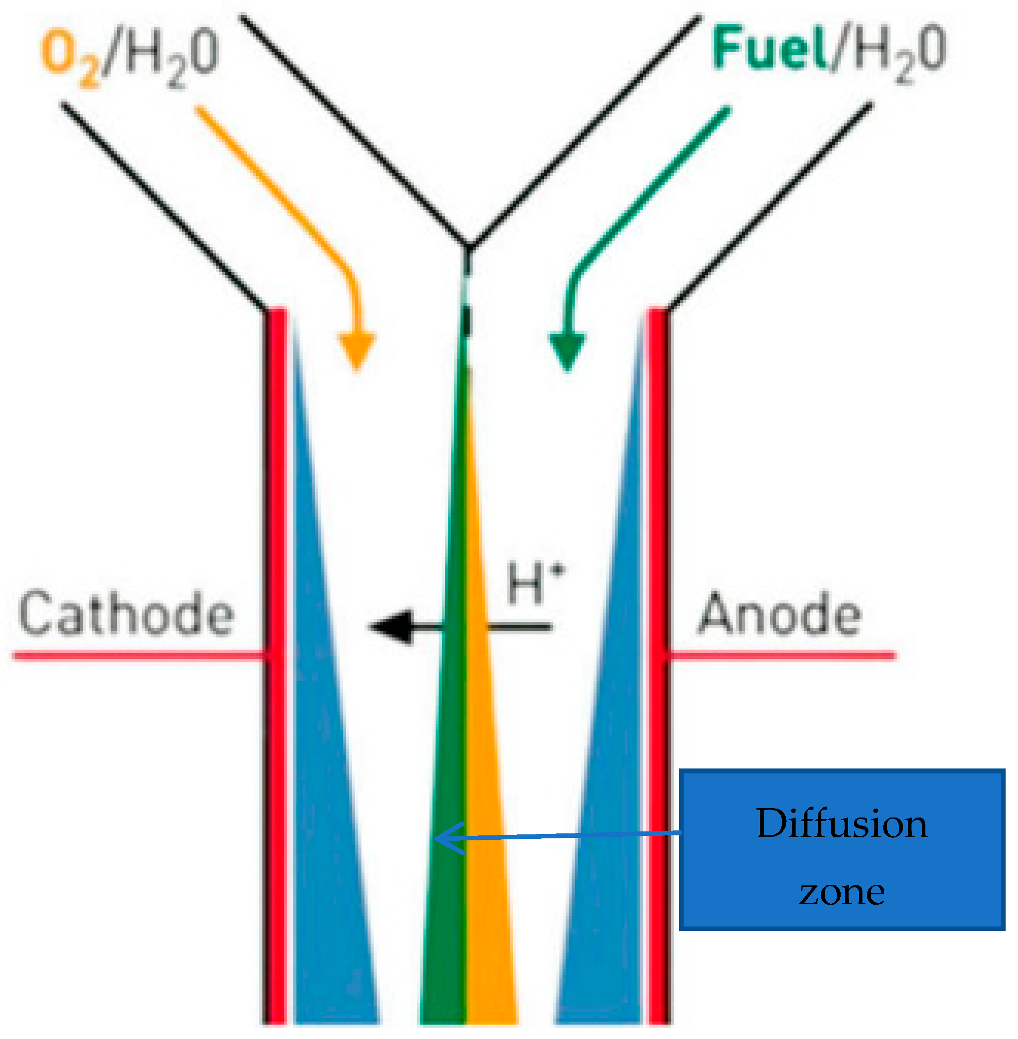
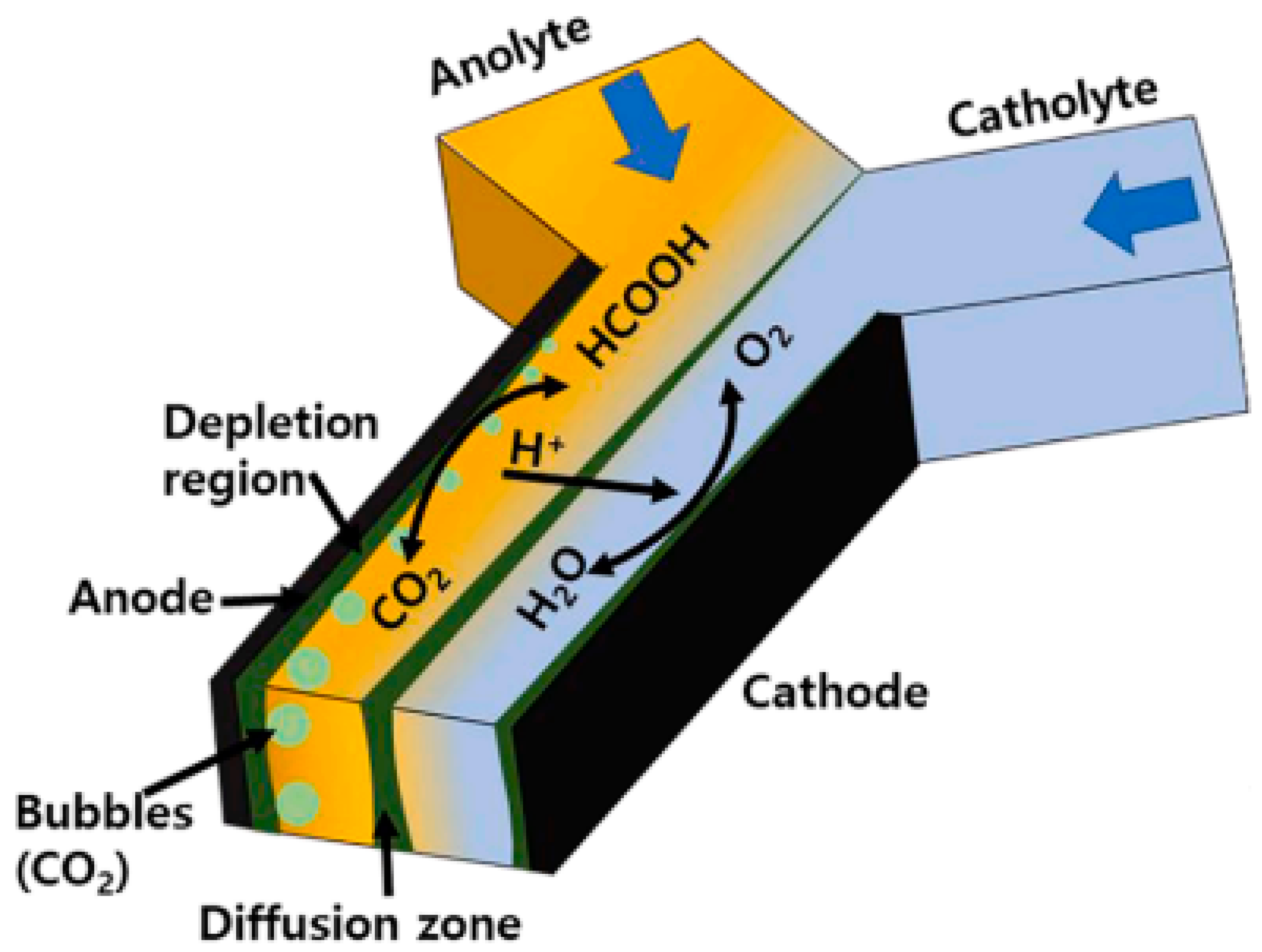
Membranes, used as separators in MFCs, are the primary requirement for optimal electrochemical and microbiological performance in such systems [9]. However, membrane drying, fuel crossover, fuel cell flooding, and anode catalyst poisoning are some of the problems associated with membrane-aided MFCs, which have been identified using electrochemical impedance spectroscopy (EIS) [41]. In addition, in fuel cells, there are two types of power loss: one is dominated by the electrical resistance between the electrodes, which is called leak resistance, and the other is dominated by mass diffusion between the anode and cathode, called crossover, which occurs via membranes. To optimize the performance, a microfluidic microbial fuel cell was designed to maximize the surface-to-volume ratios and minimize the internal resistance, leading to improved use via greener energy options. Therefore, microfluidic microbial fuel cells have emerged as attractive options [39,42,43,44]. Such devices are characterized by the laminar flow of fuel and oxidant streams, which eradicates the use of membranes for proton diffusion. These membraneless microfluidic devices have found uses in wastewater treatment [45] and electricity generation [46], and the modeling of a membraneless single-chamber microbial fuel cell with molasses as an energy source has been described by Sirinutsomboon [47]. Wang and Su (2013) [48] have also reported a membraneless microfluidic microbial fuel cell for the rapid detection of the electrochemical activity of microorganisms. They demonstrated experimentally that a membraneless MMFC was capable of identifying the electric potential resulting from the imbalanced compositions between two streams and from the electrochemical activity of microbial biofilms. Figure 3 shows a Y-shaped version of this.

2.1.3. Microbial Cell Metabolism Reactions

In MFCs, organic substrates, such as acetate and glucose, are oxidized to produce electrons, which travel through an external circuit to generate power. The bioelectrochemical process produces an electromotive force (EMF) that can be theoretically represented as [50]
E e m f = E c a t h o d e E a n a d e η
In Equation (1),   E e m f is the emf, E c a t h o d e is the half-cell potential of the cathode, E a n a d e is the half-cell potential of the anode, and η is the loss term involving dominant losses, activation losses, and mass transfer losses.
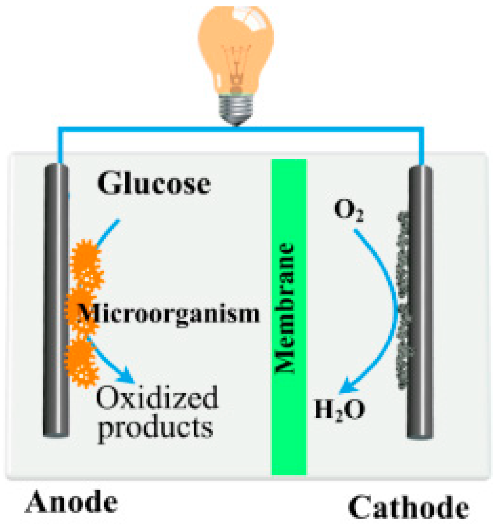
Using glucose (see Figure 4), the oxidation and reduction reactions occur, which can be described by the following reaction [51]:
Anode reaction
C 6 H 12 O 6 + 6 H 2 6 C O 2 + 24 H + + 24 e
Cathode reaction
6 O 2 + 24 H + + 24 e 12 H 2 O
The Nernst equation for a half-cell reaction gives
E h a l f c e l l = E 0 R T n F l n Q
In Equation (4), E 0 is the standard half-cell potential, R is the universal gas constant, T is the absolute temperature, Q is the equilibrium constant, and l n is the natural logarithm. Consequently, the thermodynamic feasibility of the bioelectrochemical generation of power can be calculated as [52]
G = n F E e m f
In Equation (5), G  is the change in free energy following the bioelectrochemical reaction, n is the number or electrons transferred, and F is Faraday’s constant. E e m f is defined in Equation (1).
Consequently, bioelectrochemical power generation will be feasible subject to Equation (5).

2.1.4. Electron Transfer Reaction

A bioelectrochemical system is highly integral and coordinated, where microbes and electrodes work in concert to generate an electric current. In biotechnology-based synthesis, extracellular electron transfer in microorganisms has been extensively exploited, where microbes can catalyze both anodic and cathodic biochemical reactions [53]. In microbial fuel cell technology, electron transfer from the anode to the cathode is critical to the realization of biologically mediated electrical power generation, and several mechanisms of such electron transfer have been reported, involving two major genera of bacteria known for their abilities, namely Geobacter and Shewanella [54,55,56]. The extracellular transport of electrons to electrodes takes place in three different ways as follows.
Extracellular electron transfer (EET) is a mechanism through which microorganisms obtain energy for growth and maintenance from their surroundings/substrate and transfer the resulting metabolically generated electrons to the anode to generate electrical power [57]. The transfer mechanism can either be direct, via conductive pili or nanowires, or mediated transfer that involves either naturally secreted redox mediators like flavins and pyocyanins or artificially added mediators like methylene blue and neutral red [58,59]. Most importantly, the electron transfer efficiency is controlled by the redox potential and microbial oxidative metabolism responsible for electron generation [60,61,62]. Direct electron transfer is associated with the Shewanella and Geobacter species, where electrons are directly transferred to the electrode surface; the transfer is possible because of the outer membrane cytochrome (C-type), which enhances the electron transfer from NADH [63]. This mechanism involves a few genera of bacteria, such as Shewanella and Pseudomonas. These electrogenic bacteria secrete some chemical species, such as flavins, called shuttle molecules, to enhance the electron transfer from the outer membrane of the bacteria to the electrodes [64,65]. In electron transfer via nanowires, Geobacter genera and, very recently, Shewanella have demonstrated their abilities to use their conductive appendages in an electron transfer mechanism outside the cell [66,67,68]. These microbial structures involve cellular outgrowth, known as nanowires, with reported conductivity that is much higher than that of synthetic metallic nanostructures [69,70].

2.1.5. Kinetics

Assuming that the cathode has a layer of polytetrafluoroethylene (PTFE), which is permeable to oxygen but not water, Fick’s law of diffusion governs oxygen diffusion as [71]
t O 2 P T F E = D O 2 , P T F E y 2 O 2 P T F E
In Equation (5), O 2 P T F E is the concentration of oxygen in the PTFE layer [mmol dm−3], D O 2 , P T F E is the diffusion coefficient of oxygen in the layer [μm2 min−1], and y is the diffusion distance in PTFE [μm].
The rate at which oxygen is reduced at the anode is assumed to follow the Monod and Butler–Volmer equation as [71,72]
r O 2 = k O 2 O 2 c a t / l i q K O 2 + O 2 c a t / l i q e x p 1 α c a t γ e / O 2 F R T E c a t E c a t 0
In Equation (7), r O 2 is the rate of oxygen reduction per area [mmol dm−2], k O 2 is the rate of oxygen reduction per area [mmol dm−2 min−1], O 2 c a t / l i q is the concentration of oxygen at the cathode–liquid interface [mmol dm−3], α c a t is the electron transfer coefficient of the anode [-], γ e / O 2 is the electron transfer equivalence of oxygen [mmol electron mmol-oxygen−1], F is Faraday’s constant [Cmol−1], R is the universal gas constant [Jmol−1K−1],  T is the absolute temperature [K], E c a t is the cathode voltage [V], and E c a t 0 is the standard cathode voltage [V].
The reduction is assumed to occur at the cathode–liquid interface.
Using the Nernst equation, the cathode voltage is calculated as [73]
E c a t = E c a t 0 R T γ e / O 2 F l n 1 O 2 c a t / l i q H + c a t / l i q 4
In Equation (8), H + c a t / l i q 4 is the concentration of hydrogen ions at the cathode–liquid interface.

2.2. Fibrous Microfluidic Systems

Current State of Research

Microfluidic technologies are based on processing and manipulating small amounts of fluids in channels with dimensions of tens to hundreds of micrometers [74]. In the design of microfluidic systems, poly(dimethylsiloxane) (PDMS) has been widely used. However, considering that it is highly hydrophobic, limitations and difficulties arise in flow startup among parallel microchannels, which can lead to permanent idleness and partially filled channels. In such systems, capillary pressure arising from bubbles, similar to the Jamin effect and spanning the cross-section of the microchannel, is the major force for flow blockage. The threshold flow rate necessary for uniform flow initiation in parallel microchannels can be determined by balancing the maximum capillary pressure and the hydrodynamic pressure drop [75,76]. At the micro and nano scales, fluids behave differently due to the different major forces present, and the material selection, design, and process have the potential to work together to impact the microfluidic behavior. Consequently, flow control in microchannels has been achieved by systematically integrating systems in the design, material selection, and operational conditions [77]. To mitigate the hydrodynamic problem, filling microchannels with porous fibrous matrices has been found to increase the hydrodynamic pressure drop and thus allow uniform flow startup, using appropriately low threshold flow rates. Moreover, Wen and Yang’s (2010) research work has provided an effective method of ensuring uniform flow initiation, using fibrous matrices in microchannels [76].
Freshwater resources directly available to humans account for only 2.7% of the global water resources, with the remainder accounting for salty or brackish water bodies. The problem is aggravated by the fact that freshwater resources are extremely uneven, causing serious shortages in many countries and regions [78,79,80]. The unitization of solar energy for the evaporation of seawater or sewage to improve the water quality has been proven to be an environmentally friendly and sustainable water treatment technology. However, there are still many challenges for efficient solar vapor generation, which include a lack of free floating, low water transfer rates, low energy efficiency, serious salt precipitation, and a short service life (Mei et al., 2020) [81]. In this regard, Mei et al. (2020) [81] employed photothermal conversion nanofibrous aerogels with vertically aligned microchannels, which, due to the orderly framework structure and good hydrophilicity, showed excellent underwater compressive fatigue durability and a higher water transfer rate. Moreover, the surface temperature of the system could be raised from 28 to 94 °C in air, after being solar irradiated for 30 s.
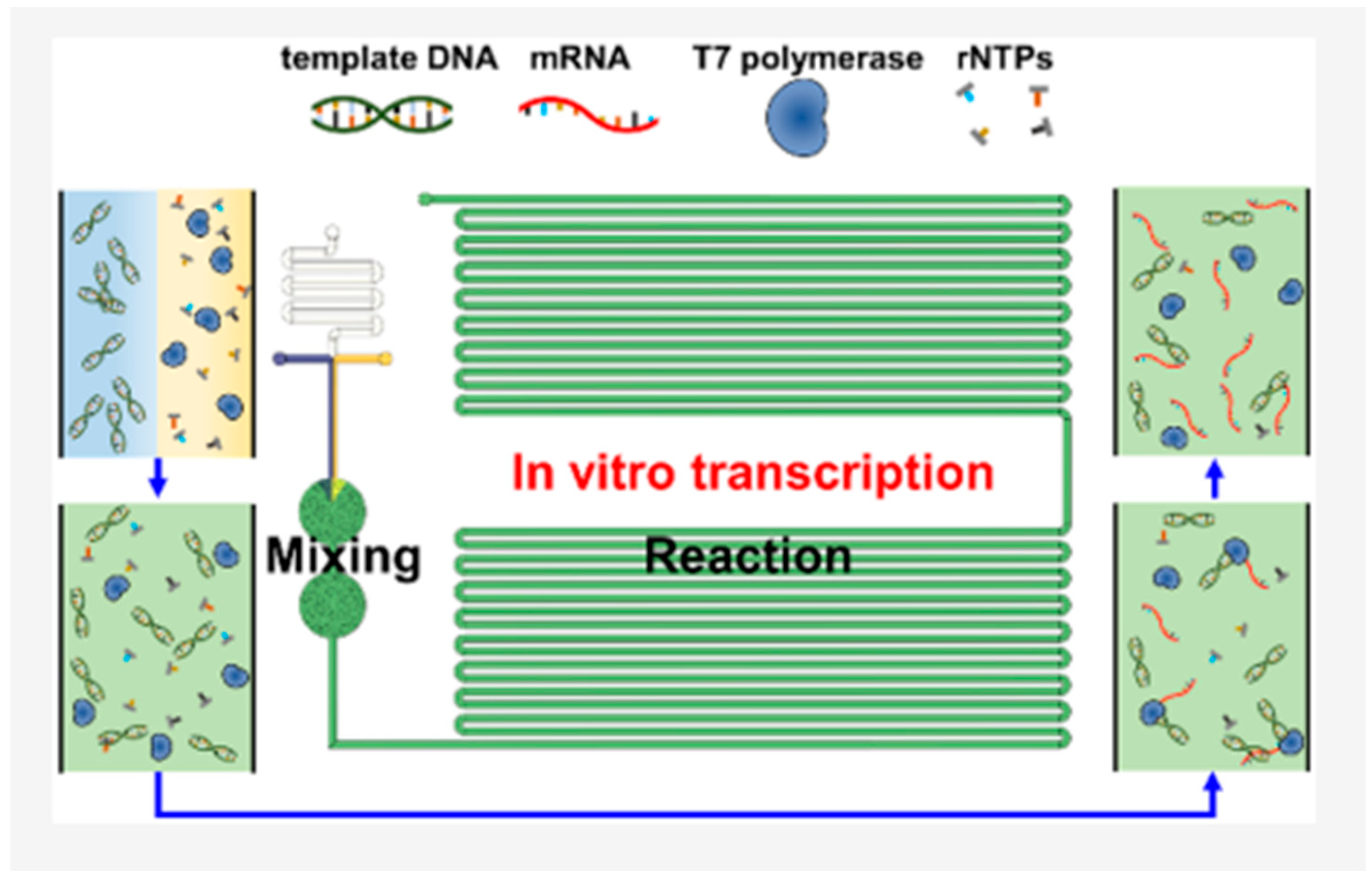
Microfluidic mixing techniques are versatile and facile alternatives to improve the reproducible production of pharmaceutics on one hand and to mimic a complex cellular microenvironment on the other in biological systems [36]. In such systems, mixing can be active and passive based on the operational mechanism, where external forces can be utilized to perform the active mixing of fluids in the microdomain. Moreover, the mixing of fluids in such microfluidic systems can be difficult because of the lamina-dominated flow regime, causing diffusive mixing to predominate [82]. Microfluidic platforms have been explored to manipulate cells and particles in biological systems for the distribution of chemical and biological species. In DNA research [83], numerous biochemical assays in multiplex systems and microarrays require the reagents/samples to be carried in contact with the functionalized surface for proper wells. In addition, based on this platform, chemical species can be separated physically from a multispecies mixture to analyze each component of the mixer, and the individual species can be purified (Vicente et al., 2020) [84]. In the research work of Choi et al. (2023) [85], a new type of microfluidic bioreactor with fibrous micromixers for ingredient mixing and a long macrochannel for the in vitro transcription reaction was successfully fabricated for the continuous production of mRNA. The diameter of the fibrous microchannels in the micromixers was tuned by using an electrospun microfibrous disc with different microfiber diameters. The research work demonstrated that the continuous reaction in the microfluidic bioreactor with efficient mixing performance could serve as a powerful platform for various microfluidic reactions, with mixing efficiency of 95% (see Figure 5).
The advent of microstructure fibers with μ-channels brings the possibility of in-fiber-integrated microfluidic devices, and microstructure fibers with μ-channels provide the possibility of creating new online monitoring systems. In this regard, Zhang et al. (2022) [86] have developed a novel compact in-fiber detection platform, which has been combined with a μ-channel in a new type of microstructure fiber, a side-hole fiber, for in-fiber detection. The optical component of the proposed in-fiber detection device is composed of a simple cross-axial open-cavity Fabry–Perot interferometer. The proposed device demonstrates the benefits of a simple structure, easy fabrication without additional sensitive materials, and potential application in breath sensing or lab-in-fiber technology.
In the field of fluorescence sensing, fibrous microchannel systems have been found to be beneficial. Thus, Irawan et al. (2006) [87] have reported a compact and practical fluorescence sensor based on an in-fiber microchannel. Their device consisted of a blue LED, a multimode silica fiber, and a mini-PMT, these being used as a source of excitation, a light guide, and a fluorescence detector, respectively. The experimental results showed that the sensor had high sensitivity, with the capability to detect 0.005 µg L−1 of fluorescein in the required solution, while the experimental results were reproducible. Their experimental results also demonstrated that the silica fiber sensor had better sensitivity than a polymethyl methacrylate (PMMA) fiber sensor.
From the extensive review of Section 2.1, there is no literature that specifically links the electric double layer theory to microbial/microfluidic microbial fuel cells. The following sections will fill this knowledge gap.

2.3. Evolution of the Electric Double Layer in Microfluidic Channels—Site Dissociation Model

We consider a microfluidic channel with pH-dependent surface-ionizable groups [88,89] and a definite point of zero charge pH. Under these conditions, the site dissociation reactions can be represented as [90]
M O H M O + H +
M O H + H + S O H 2 +
In Equations (9) and (10), M O H  is a surface-ionizable species,   M O is a deprotonated surface-ionizable species,   S O H 2 + is a protonated surface-ionizable species, and H + is a surface hydrogen ion.
Equations (9) and (10) describe surface-ionizable dissociation above and below the point of zero charge pH, respectively.
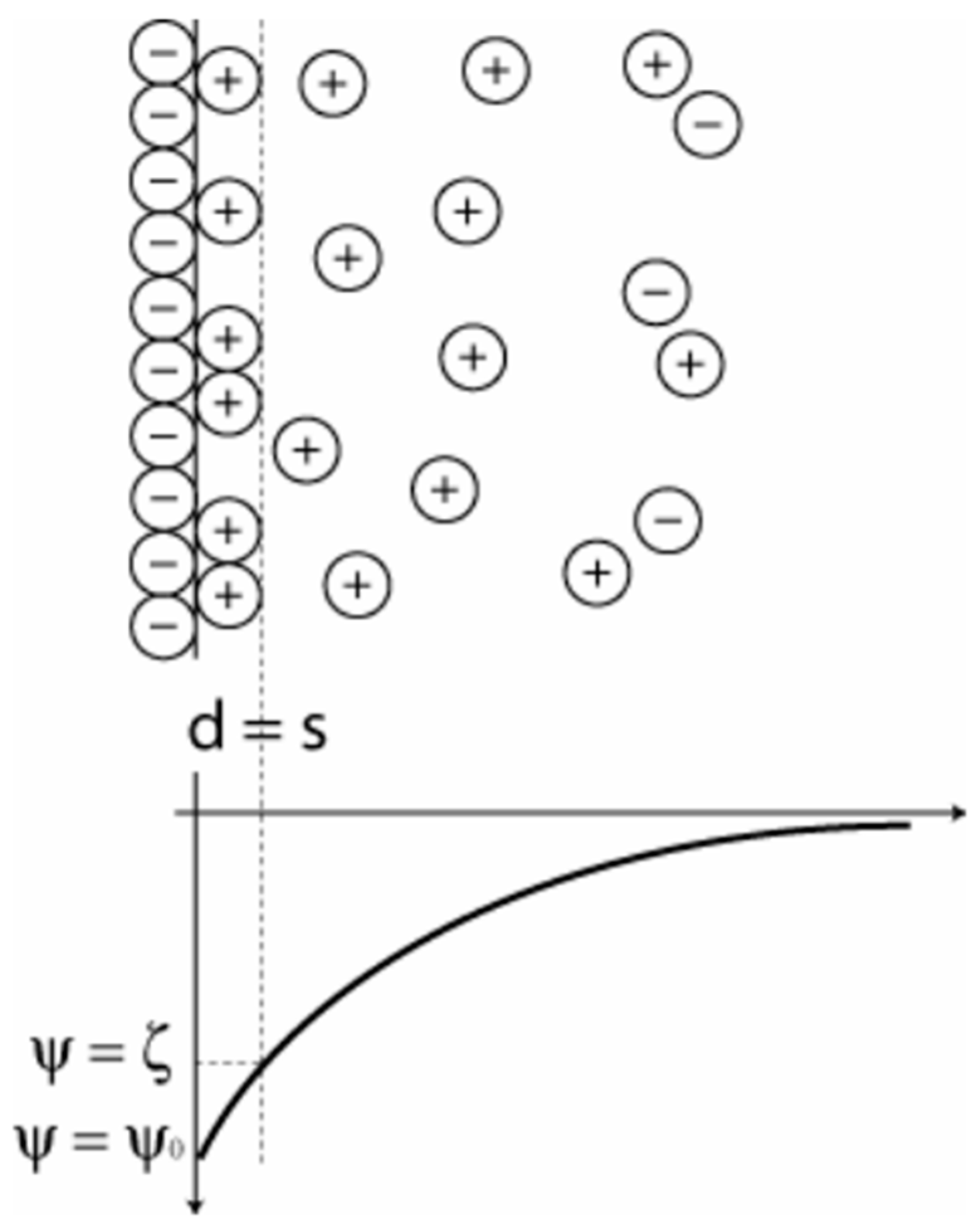
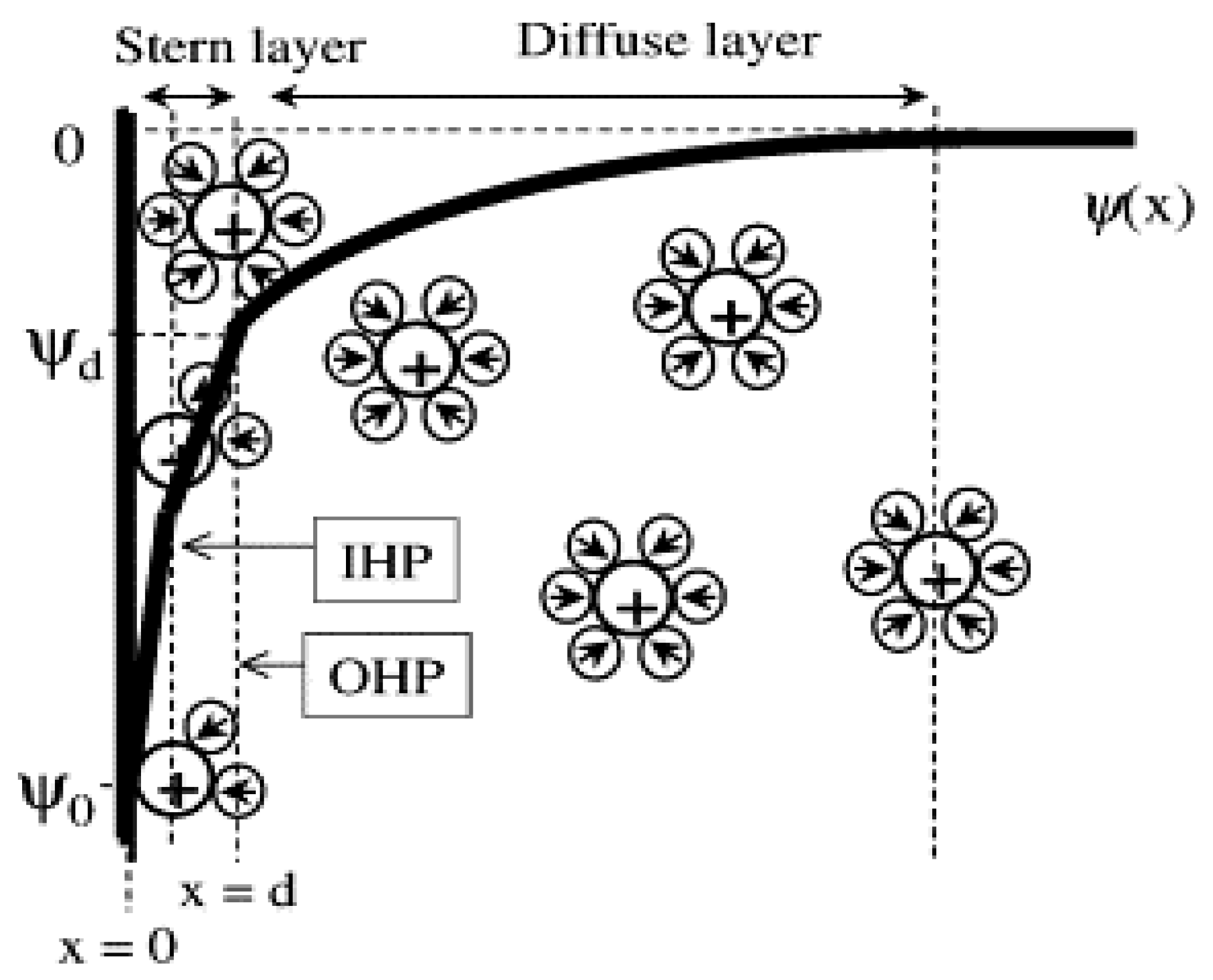
Following the dissociation reactions described by Equations (9) and (10), counter-ions in the electrolyte solution adsorb on the ionized surfaces, with co-ions being attracted to the counter-ion layer. Under these conditions, an electric double layer evolves, having a diffuse layer (see Figure 6). For such a system, to calculate the surface potential and surface charge density, the mean field theory of Poisson–Boltzmann approximation [91,92,93] provides a theoretical approach to determining the potential distribution within the electric double layer.
For a microfluidic channel with an electric-double-layer-dependent surface charge density, the electroviscous effect is prominent, and the solution of the classical Navier–Stokes equation with an electric body force provides the theoretical foundation for the calculation of the effective flow rate under different operational and design conditions of microfluidic systems, which is needed to understand the performance of MMMFCs. This aspect will be considered in the appropriate section.

2.4. Electric Double Layer of Microbial Systems

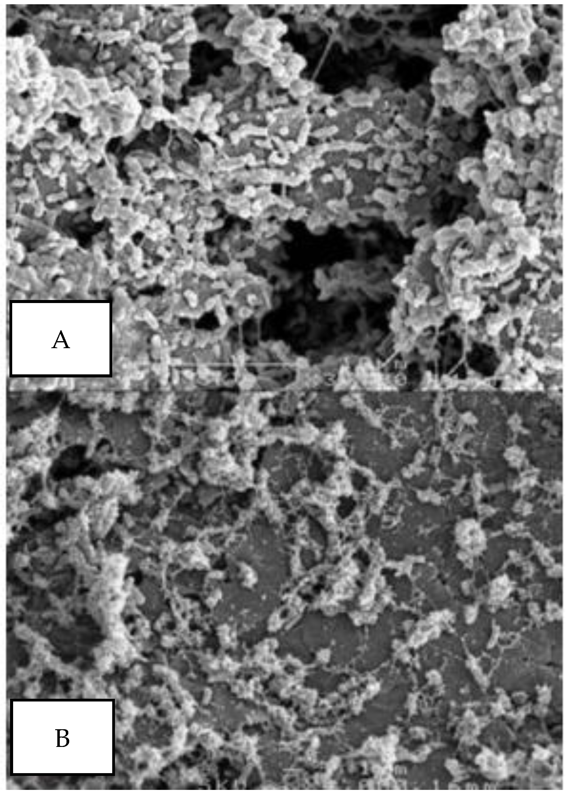
The existence of a bioelectrochemical power system depends on the presence of microbial biofilms on anodes (Read et al., 2010) [95]. Figure 7 shows scanning electron microscope images of P. aeruginosa biofilms at 72 h (3000×) and 144 h (3000×) in a continuous mode. Structurally, the biofilms consist of extracellular polysaccharide and microbial cells, where the latter account for 50–90% of the total organic carbon, forming the primary matrix material [96].
Dextran is a microbial exocellular polysaccharide consisting of crucial α-1,6 interconnected D-gluco-pyranose groups with a small number of α-1,2-, α-1,3-, or α-1,4-linked side chains (Figure 8).
In addition to polysaccharides, the surface functional group chemistry of intact Gram-positive and Gram-negative bacterial cells has been investigated as a function of the solution pH, growth phase, and growth media based on attenuated total reflectance Fourier transform infrared (ATR-FTIR) spectroscopy, where the functional groups of the cell wall hydroxyl, carboxyl, phosphoryl, and amide groups have been identified [98]. Each of these functional groups exhibits pH-dependent ionization [99,100].
Consequently, bacterial cell surfaces carry a net negative charge under most physiological conditions, with a few notable exceptions [101,102], implying the existence of an electric double layer on microbial cells. Accordingly, Table 1 summarizes the information on the ionization of ionizable functional groups, as well as their molecular relationships.
The surface of a bacterial cell with carboxyl and amine base groups with number densities per unit area N1 and N2, respectively, and Ka1 and Ka2, respectively, have a fixed surface charge density [104]. For a typical electric double layer characteristic of a microbial system, Figure 9 shows a schematic of the distribution of ions and the associated potential near a charged microbial surface, based on the Stern–Grahame model [105].
Based the model of Figure 9, the amount of specifically adsorbed charge per unit area in solution per unit area can be expressed using the Langmuir isotherm as [105,106]
σ a d s = z e C N a d s e x p Δ a d s G / k B T + C e x p Δ a d s G / k B T
where
Δ a d s G = z e ψ + Δ s p e c G
In Equations (11) and (12), z e ψ denotes the electrostatic interaction energy and Δ s p e c G is the Gibbs energy of a specific interaction; N a d s is the number of adsorption sites per unit area; and C and z represent the bulk electrolyte concentration and the valence of specifically adsorbing ions, respectively.
Consequently, the application of the mean field approximation of the Poisson–Boltzmann equation in the analytical solution of the potential distribution in the electric double layer of a microbial system is permissible [107], and its possible effect on microbial cell performance deserves attention.

2.5. Interrelationship of the Electric Double Layer and Microfluidic Systems

2.5.1. Electrostatics and Hydrodynamics

Different flow channels can be assumed for microfluidic systems, such as circular systems [108] and rectangular systems [109,110]. In this paper, we assume a cylindrical microfluidic system, on the surface of which an electric double layer evolves from the absorption/dissociative reactions of the surface-ionizable functional groups of rock minerals in contact with an electrolytic solution [11,111]. The potential distribution of such a system obeys the Poisson–Boltzmann equation (PBE) [112,113,114]. In the cylindrical domain, it reads as follows [115]:
1 r d d r r d ψ d r = Κ 2 s i n h ψ
In Equation (13), r is the radial distance [m], ψ is the potential [V], and Κ is the reciprocal of the Debye length scale [m−1] given as (Silva et al., 2022) [116]
λ D = N A e 2 ϵ 0 ϵ r k B T i n c i z i 2
in which λ D is the Debye length [nm], c i is the bulk electrolyte concentration of an ionic species [molm−3], z  is the ion valence [-], e is the electronic charge [C], ϵ 0 is the permittivity of free space [Fm−1], ϵ r is the relative permittivity [-], k B is the Boltzmann constant [JK−1], N A is Avogadro’s number [mol−1], and T is the absolute temperature.
From Equation (13), it is possible to solve for the potential distribution as a function of the distance from the solid–electrolyte solution interface and, therefore, for that on the surface. Generally, the higher the surface potential/surface charge density, the higher the zeta potential, which translates to lower salinity [117,118]. Moreover, when the electrostatic free energy, calculated as the product of the electronic charge, surface potential, and valence number, compared to the Boltzmann thermal energy is very small, Equation (13) can be used to conform to the Debye–Hackle approximation as [119]
1 r d d r r d ψ d r = λ 2 ψ
Equation (15) is the linearized form of the PBE [106,116].
The boundary conditions for the analytical solution are the following:
ψ = ψ s   at   r = R
d ψ d r = 0   at   r = 0
Assuming a cylindrical channel, the solution to Equation (15), based on the appropriate boundary condition, is given as [120,121]
ψ r = ψ s I 0 Κ r I 0 Κ R
in which, ψ s is the surface potential [V], I 0 is the zero-order modified Bessel function, R is the radius of the cylinder, and Κ = λ D 1 is the reciprocal of the Debye length scale [m−1].
Equation (18) is the theoretical foundation for subsequent development regarding the surface charge density–potential relationship for the electrokinetic system, and attention will be given to this in the appropriate section.

2.5.2. Electrokinetics of the Flow Regime

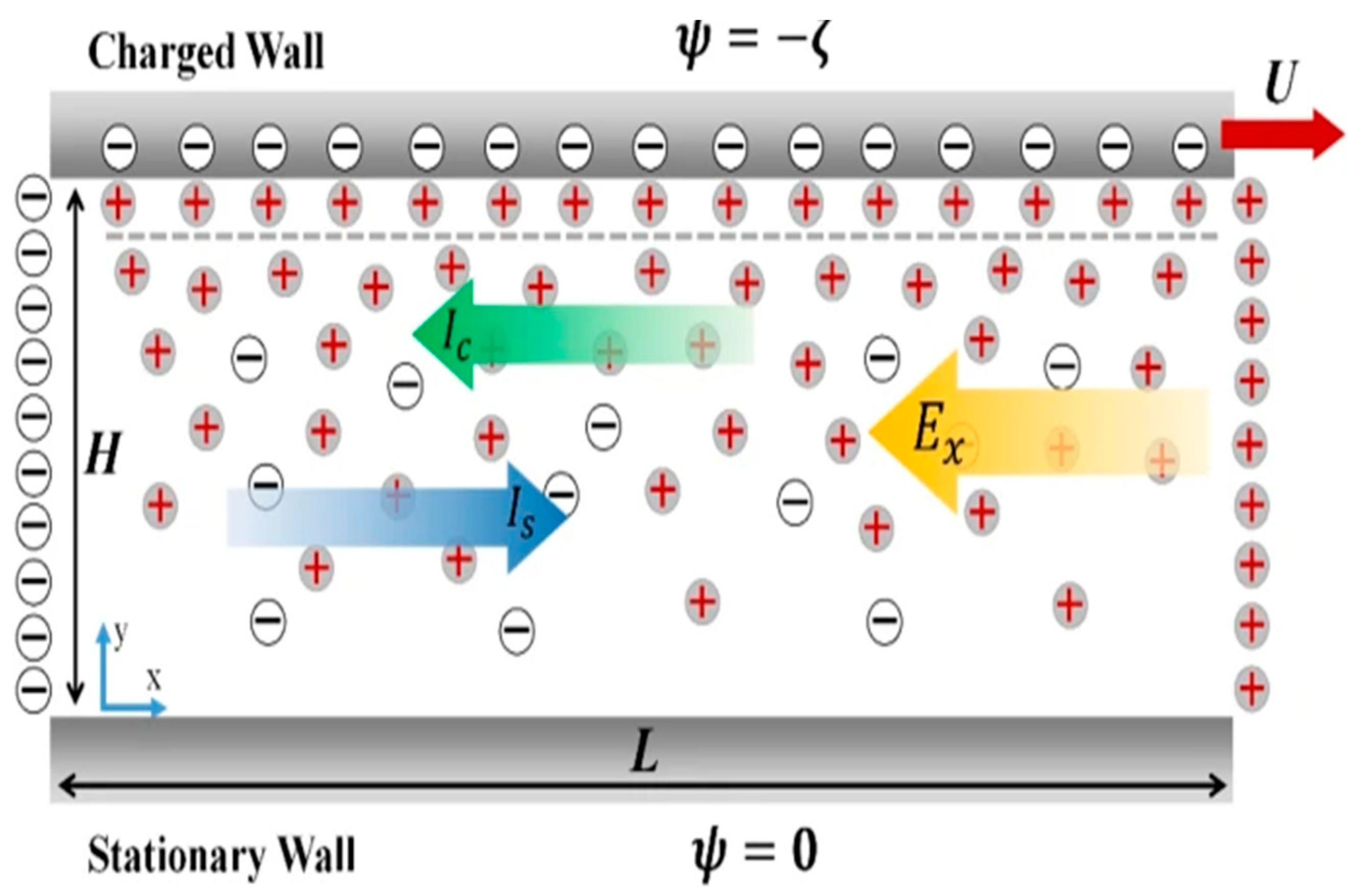
The phenomena of the streaming potential and streaming current occur due to the charge displacement in the EDL caused by an external driving force displacing the liquid phase tangentially against the solid at the solid–liquid interface [121]. Consequently, the counter-ions in the diffusive part of the EDL are carried downstream in response to a pressure gradient. The resulting streaming current results from the pressure-driven flow direction of the electrolyte solution. The process generates a streaming potential φ, corresponding to the streaming current. The flow-induced streaming potential causes the counter-ions in the mobile part of the EDL to move in the direction opposite to the streaming current, causing the opposite-directional flow of ions to generate a conduction current in the Stern layer. The net effect is a reduced flow rate in the direction of the pressure drop, referred to as the electroviscous effect [122,123]. The accumulation of ions sets up an electric field Ez with the streaming potential difference φ. This field causes the conduction current to flow back in the opposite direction. At a steady state, the net current should be zero [124,125]. The following Figure 10 summarizes the schematics of the hydrodynamic regime in the presence of the electric double layer.
Following the effect of the streaming-current-induced potential difference in the flow regime, the classical Navier–Stokes equation for flow in a cylindrical geometry reads [126]
1 r d d r r d u d r = 1 η d P d L ρ e E L
where
E L = d φ s d L
In Equation (19), ϕ s is the streaming potential [V] and L is the distance in the flow direction.
ρ e = ϵ 2 ψ = ϵ Κ 2 ψ s I 0 Κ r I 0 Κ R
The substitution of Equations (20) and (21) into Equation (19) gives the modified Navier–Stokes equation for the electrokinetic effect as
1 r d d r r d u d r = 1 η d P d L + ϵ Κ 2 ψ s η I 0 Κ r I 0 Κ R d φ s d L
The boundary conditions are the following:
u L r = 0   at   r = R
d u L r d r = 0   at   r = 0
The solution gives
u L r = R 2 r 2 4 η Δ P L ϵ ψ s η 1 I 0 Κ r I 0 Κ R Δ φ s L
The streaming potential is given as [126]
Δ ϕ s = π R c 2 ϵ φ s η 1 1 2 Κ R I 1 Κ R I 0 Κ R Δ P L R ~ π R c 2 ϵ 2 Κ 2 ψ s 2 η 1 2 Κ R I 1 Κ R I 0 Κ R I 1 2 Κ R I 0 2 Κ R
E L = d φ s d L = Δ P L π R c 2 ϵ φ s η 1 1 2 Κ R I 1 Κ R I 0 Κ R L R ~ π R c 2 ϵ 2 Κ 2 ψ s 2 η 1 2 Κ R I 1 Κ R I 0 Κ R I 1 2 Κ R I 0 2 Κ R
Substitution into the velocity profile of Equation (25) gives
u L r = R 2 r 2 4 η Δ P L ϵ ψ s η 1 I 0 Κ r I 0 Κ R Δ P L π R c 2 ϵ φ s η 1 1 2 Κ R I 1 Κ R c I 0 Κ R c L R ~ π R c 2 ϵ 2 Κ 2 ψ s 2 η 1 2 Κ R I 1 Κ R c I 0 Κ R c I 1 2 Κ R c I 0 2 Κ R c
Equation (28) can be written as
u L r = R 2 r 2 4 η Δ P L 1 I 0 Κ r I 0 Κ R A
in which
A = ϵ ψ s η Δ P L π R c 2 ϵ φ s η 1 1 2 Κ R I 1 Κ R c I 0 Κ R c L R ~ π R c 2 ϵ 2 Κ 2 ψ s 2 η 1 2 Κ R I 1 Κ R c I 0 Κ R c I 1 2 Κ R c I 0 2 Κ R c
The total flow rate through the microfluidic channel is given as [127]
q = r m f + r m c 2 π r u L r d r
The substitution of the radial velocity dependence from Equation (29) into Equation (31) gives the total flow rate as
q = r m f + r m c 2 π r u L r d r = r m f + r m c 2 π r R 2 r 2 4 η Δ P L 1 I 0 Κ r I 0 Κ R A d r
The interrelationship of this equation with microfluidic microbial fuel cell performance will be discussed in the appropriate section.

2.6. Influence of Electrokinetics on Viscosity

2.6.1. Primary Electroviscous Effect

The electric double layer has been known to affect the viscosity, and its combined effect in the presence of the zeta potential and pH on the apparent viscosity of non-Brownian suspensions has been reported [128]. Consequently, the effect consists of the primary electroviscous effect (PEE) stemming from the distortion of the electric double layer under a shear field [129,130] and the secondary electroviscous effect (SEE) resulting from the overlap of the electric double layer [131]. The most recent analysis of the PEE, covering a wide range of κa and zeta potential values, was developed by Watterson and White, and the derivation was presented as [132]
P ζ , Κ a 3 k B T 10 π μ 0 e 2 i = 1 N n i α z i 2 λ i i N n i α z i 2 L Κ a e ζ k B T 2
In Equation (33), P ζ , Κ a is the primary electroviscous effect as a function of the zeta potential ( ζ ) and the dimensionless electrokinetic radius ( Κ a ), is the permittivity of the electrolyte solution [Fm−1], k B is the Boltzmann constant [JK−1], T is the thermodynamic temperature [K], and n i α is the bulk concentration of an ionic species i [m−3].
λ i is the conductance of the ith ionic species [mSm2mol−1] defined as
λ i = N A e 2 | z i | Λ i 0
where Λ i 0 is the limiting conductance of the ith ionic species [mSm2mol−1], N A is Avogadro’s number [mol−1], e  is the electronic charge [C], and | z i | is the absolute value of ionic valence [-].
L Κ a = 10 π 3 Z Κ a 1 + Κ a
Z Κ a is a function of the dimensionless electrokinetic radius ( Κ a ) as
Z Κ a 200 π Κ a 1 + 11 Κ a 3200 π
For high-salinity systems with thin electric double layers,
Z Κ a 3 2 π Κ a 4
In Equations (35) to (37), a is the radius of a colloidal spherical particle [133] with its associated electric double layer and electrokinetic effect. For microfluidic systems, these equations can be written by substituting the radius of the channel for a. The implication is that, with the existence of the EDL in microfluidic systems, viscosity modifications in accordance with the primary and secondary electroviscous effect are imminent. The following section is devoted the theoretical aspects in the literature.

2.6.2. Apparent Viscosity

The implication of Section 2.6.1 is that both the PEE and SEE phenomena will cause a viscosity increase in microfluidic systems, as found in emulsion systems [134,135]. The apparent viscosity μa is the combined result of the electroviscous effect and boundary slip on fluidic flow. To characterize the influence of the electroviscous effect on fluidic flow, the apparent viscosity μa is quantified for a slit flow as follows [136].
μ a = d p d x h 3 3 1 0 h u d y
In Equation (36), μ a is the apparent viscosity [Pa·s], d p d x is the pressure gradient [Pa·sm−1], h is the width of the slit [m], u is the analytical solution for the velocity profile, and y is the distance measured relative to the channel wall [m].
Equation (38) can be written for a cylindrical microchannel using the velocity profile in Equation (29) as
μ a = d p d x R C 3 3 1 0 R C u r d r = d p d x R C 3 3 1 0 R C Δ P L 1 I 0 Κ r I 0 Κ R A d r
In such systems, analytical derivations exist for the surface potential and surface charge density. The following section will be devoted to their theoretical review.

2.6.3. Potential and Surface Charge Density Relationships

The surface charge density for the cylindrical surface is given as [137]
d ψ d r = 4 π σ ϵ r ϵ 0   at   r = R   which gives :
The generalized approach to differentiating the modified Bessel function of any order is given as [138]
d d r I n x I n Κ R = 0 Κ r I n x + I n + 1 x = I n + 1 x
Therefore, from Equation (40),
d ψ d r = ψ s I 0 Κ R e f f I 1 Κ r
Combining Equations (41) and (42) gives the surface charge density–potential relationship as
σ = ϵ r ϵ 0 4 π ψ s I 0 Κ R I 1 Κ R
where the surface potential ψ s is given as
ψ s = 4 π σ ϵ r ϵ 0 Κ I 1 Κ R I 0 Κ R
The surface potential can be written in terms of the Nernst equation as [139,140,141]
ψ s = 3.301 k B T e p H p z c p H
in which p H p z c is the point of zero charge pH k B is the Boltzmann constant [JK−1], T is the absolute temperature, e is the electronic charge [C], and p H is the negative base 10 logarithm of the hydrogen ion concentration of the electrolyte solution in contact with the solid surface.
Consequently, the pH-dependent surface charge density can be written as
σ = ϵ r ϵ 0 4 π 1 I 0 Κ R I 1 Κ R 3.301 k B T e p H p z c p H
Combining Equations (45) and (46), the pH-dependent surface potential reads
ψ s = 4 π ϵ r ϵ 0 Κ I 1 Κ R I 0 Κ R ϵ r ϵ 0 4 π 1 I 0 Κ R I 1 Κ R 3.301 k B T e p H p z c p H
In Equation (43), ϵ r is the relative permittivity of the electrolyte solution [-], and ϵ 0 is the permittivity in vacuo [Fm−1].

2.6.4. Fibrous Microfluidic Systems

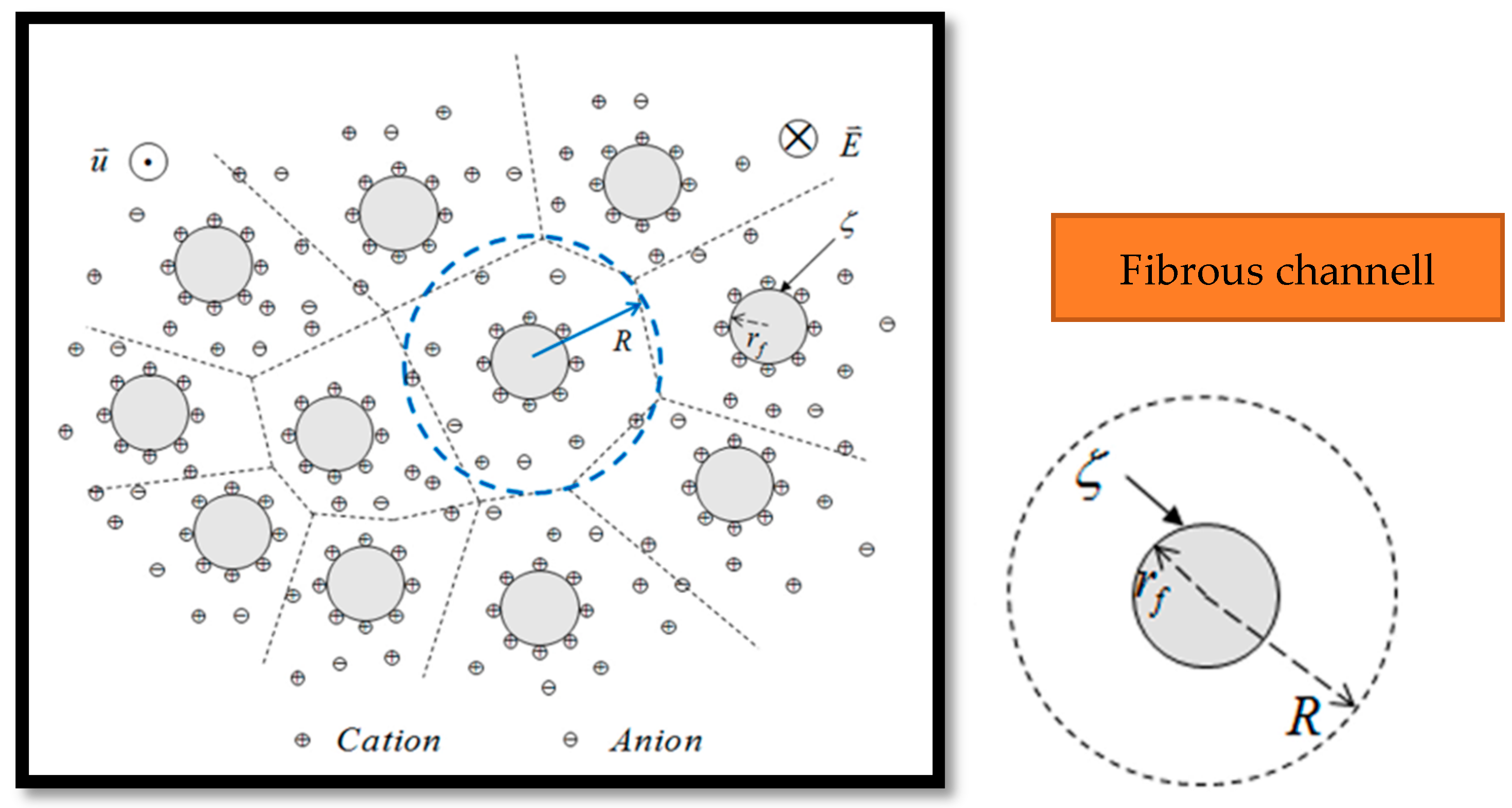
In line with the potential of fibrous microfluidic systems (see Section 2.2), we consider a fibrous microfluidic system with fibers containing pH-dependent ionizable groups. See Figure 11.
Assuming a cylindrical system with a given porosity, the analytical solution for the linearized Poisson–Boltzmann equation based on the mean field approximation is given as [68]
ψ = ζ K 1 Κ R I 0 Κ r + I 1 Κ R K 0 Κ r K 1 Κ R I 0 Κ r f + I 1 Κ R K 0 Κ r f
In Equation (42), r f is the radius of the fiber [m] and R is the radius of a circular cell in the fibrous bundle [m].
Equation (46) is derived based on the following boundary conditions [142]:
ψ   a t   r = r f = ζ
ψ r   a t   r = R = 0
The velocity profile is given as [142]
u = 1 χ 2 μ d p d x K 1 χ R I 0 χ r + K 1 χ R K 0 χ r K 1 χ R I 0 χ r f + I 1 χ R K 0 χ r f 1
where
χ = ρ e μ λ = ϵ Κ 2 ζ μ λ
ρ e is the net charge density given as
ρ e = ϵ Κ 2 ψ
In Equation (52), λ is the electrical conductivity of the electrolyte solution.
Based on Equation (51), the flow rate through a circular unit cell of the fiber bundle can be derived from elementary calculus as [142]
q = r f R 2 π r u d r = 2 π χ 2 μ d p d x K 1 χ R I 0 χ r + K 1 χ R K 0 χ r K 1 χ R I 0 χ r f + I 1 χ R K 0 χ r f R 2 r f 2 2
Therefore, for a bundle of a microfluidic system with N circular such cells, the total flow rate is can be given, based on Equation (54), as
q T = N t o t a l 2 π χ 2 μ d p d x K 1 χ R I 0 χ r + K 1 χ R K 0 χ r K 1 χ R I 0 χ r f + I 1 χ R K 0 χ r f R 2 r f 2 2
In Equation (55), q T is the total flow rate of a microfluidic fibrous channel consisting of N t o t a l total cellular cells in the bundle.

2.7. Implications for Performance of Microfluidic Microbial Fuel Cells

The performance of MMMFCs is governed by various parameters found in the mathematical models presented earlier, and the following sections will be devoted to discussing the interrelationship of the EDL and these parameters associated with the performance.

2.7.1. Electric Double Layer Effect

Electrostatic interactions are one of the key characteristics of bacterial cell walls [143]. Consequently, like metal oxides and clay nanoparticles particles, it is possible to obtain a speciation model for the surface sites of bacterial cell wall surfaces responsible for an electrical double layer. In this regard, the surfaces of Gram-positive bacteria, for example, contain peptidoglycan, whose molecules are rich in three types of reactive ionizable surface groups, identified as carboxylic acid (>COOH), amine (>NH+), and phosphate (>PO), where >denotes a functional group attached to the cell wall [103]. These pH-dependent ionizable surface groups can undergo protonation and deprotonation with definite ionization constants as [103]
< C O O H 0 > C O O + H +
< N H 3 + > N H 2 0 + H +
< P O 4 > P O 4 H 0
Therefore, considering Equations (56) to (58), the ionized surface species C O O , N H 3 + , and P O 4 will attract positive ions, negative ions, and positive ions, respectively, when in contact with aqueous solutions in an MFC environment (see Figure 12).
This electrostatic interaction process will lead to the attraction of counter-ions, which will automatically lead to the formation of the diffuse layer that is characteristic of the EDL. The following section will discuss its effect on MFC performance.

2.7.2. Relationship with MFC Performance

Electrostatic phenomena, such as double layer repulsion between overlapping electric double layers, the stability of colloidal systems enhanced by electrostatic repulsion, and the adsorption of oppositely charged ions/species onto charged substrates, are fundamental to the electric double layer theory [144]. Moreover, the closely related wettability phenomenon is governed by electrostatic and van der Waals intermolecular forces that are well modeled by the Frumkin–Derjaguin equation [145]. In addition, apart from the temperature, salinity is a fundamental state variable of the electric double layer system by virtue of its effect on the dielectric permittivity, which appears in models of the surface potential and surface density [146]. These three fundamental characteristics of the electric double layer provide an impetus for its linkage to some literature-based observations of MFC performance, which is the focus of our extensive review work. It is known that increased salinity enhances MFC performance regarding the power output due to increased conductivity, which decreases the internal resistance of the system, thereby enhancing proton transfer [147]. However, regarding salinity, two research works have reported optimum salinities that show a substantial difference. In this regard, while Lefebvre et al. (2012) [147] report optimum salinity of 20 gL−1, Tremouli et al. (2017) [148] report an optimum value of 4.1 gL−1. Such a striking difference in the optimum salinty values suggests that the type of bacteria used as a biocatalyst is the cause of such observations. Consequently, the salinity effect deserves to be treated with caution regarding a general conclusion about salinity in the context of the present review. Moreover, the inoculum types clearly affect the internal resistance (Rin) and power production of MFCs, where a pure culture inoculum (such as G. sulfurreducens) shows the lowest internal resistance with the highest Coulombic efficiency and energy conversion efficiency, while mixed culture inocula from soil with high concentrations of nonelectrogenic biocatalysts show the highest resistance [149]. Moreover, Shirkoh et al. (2022) [150] have demonstrated experimentally that Shewanella oneidensis requires less activation energy to extract electrons from substrate oxidation than E. coli, implying that the metabolic pathways of S. oneidensis may be smoother than those of E. coli and there is a reduced loss of nanowires compared to mobile electron shuttles.
In recent times, carbon-based anodic materials have been used in MFCs [151]. In wastewater recycling technology using MFCs, the anode is one of the most important parts. Recently, different types of anode materials have been developed to enhance the removal rate of pollutants, in addition to increasing the efficiency of energy production. In such systems, carbon-based materials have been employed as the most preferred anode material [152] due to the corrosion potential of traditional metal-based anodes [153]. Various analytical techniques involving electrochemical characterizations and infrared spectroscopy reveal that the surfaces of carbon-based materials have C=O, OH, and O-C=O functional groups [154]. In contact with a substrate/fuel-loaded wastewater/aqueous media, a surface charge develops on such anodes due to the ionization of the functional groups. Under the pH conditions typical of such systems, negative charges develop. Bacterial polysaccharides are known to be distinct due to their higher purity, hydrophilic nature, and finer three-dimensional fibrous structure, primarily providing protection, support, and energy for microbes [155]. For instance, the existence of a microbial biofilm at the interface between a hydrophobic organic substrate and aqueous medium that enables it to metabolize the substrate for energy and growth is a perfect model in this regard [156]. Meanwhile, bacterial cell surfaces possess a net negative electrostatic charge due to the presence of ionized phosphoryl and carboxylate substituents on the outer cell envelope macromolecules exposed to the extracellular environment. Therefore, considering the surfaces of microbes and that of the anode, the development of the EDL is prominent, as has been reported in the literature [157]. Therefore, in the context of the present review, which links MFCs to the EDL, there is an important electrostatic effect on MFC performance due to the electrostatic repulsion between the biofilm and the surface of the anode, reducing the biofilm attachment efficiency and electron transfer, which constitutes the MFS power. Interestingly, this inference is supported in the literature, where the negative surface charge of biochar has been shown to prevent a biofilm from adhering to anodic materials [158]. The impolication is that, in the context of the present paper, the effect of the EDL is to reduce the MFC power due to the negative regulating effect of the electrostatic repulsion [159] for carbon-based anodes.

2.7.3. pH Effect

The existence of the electric double layer on microfluidic channels and on microbial surfaces is due to the pH-dependent protonation and deprotonation reactions of surface functional groups. Consequently, it is not uncommon for the surface charge densities of substrates or bacterial cell surfaces to be pH-regulated [160,161,162,163]. From Section 2.6.3 the pH-dependent surface charge is given as
σ = ϵ r ϵ 0 4 π 1 I 0 Κ R I 1 Κ R 3.301 k B T e p H p z c p H
The implication for Equation (40) is that as the pH increases, the surface charge density becomes increasingly negative. Therefore, from Equation (44), it stands to reason that there exists an optimum pH for MFC/MMFC operation. Consequently, Banerjee et al. (2023) [164] have reported that the best performance of the MFC occurs when the pH of the aqueous solution at the anode is 8, in the presence of a chemical oxygen demand (COD) of 632 mg/L, with the maximum power density and microbial electrochemical efficiency being 138 mW/m2 and 71%, respectively. In the literature, the surface charge density has been linked to the number density of ionizable surface groups, where direct proportionality is applicable [165]. Consequently, the higher the number density of ionizable surface groups in microbial fuel cell/microfluidic systems, the higher the surface charge density.

2.7.4. Effect of Surface Chemistry

The surface chemistry of a substrate reflects its crystal property, which has an influence on its isoelectric/point of zero charge pH [166]. Above the point of zero charge pH ( p H p z c )/isolectric point, a substrate develops a net negative charge [167]. Moreover, from Equation (40), the higher the point of zero charge pH ( p H p z c ), the lower the surface charge density at a given solution pH. In MFCs, the removal of organic substances by MFCs is accomplished through a biological process called biodegradation, and the most important factors that affect the performance of MFCs are the electroactive microbial communities [168]. Based on Equation (40), the implication for performance is that the higher the point of zero charge pH of electrogenic bacteria, the lower the surface charge density at a given pH, and the more efficient the performance. On the other hand, the research work of Bakonyi et al. (2018) [168] shows that different electrogenic microbes have different substrate degradation and electron transfer capabilities. Their findings, therefore, support Equation (40), apparently due the fact that different electrogenic bacteria can have different point of zero charge pH values.

2.8. Implications of Hydrodynamics and Electrokinetics on MMFC Performance

2.8.1. Impact of Flow Rate on MMFCs

In reaction engineering related to chemical engineering unit operations, the effect of the volume flow rate on the reactor performance and pressure drop has been reported [169,170,171]. Considering a microfluidic microbial fuel cell (see Figure 12), the volume of the anolyte containing the fuel for microbial respiration will depend on several factors. These are identified in Equation (54), which is the analytical solution to Equation (30), using the Maple software version 15. From the given pressure gradient, the radius of the microfluidic channel, the dimensionless electrokinetic radius, and the dynamic viscosity, the solution leads to the following flow rate equation:
q = 22 π r 2 π r m c η Δ P 1 4 r m c 2 1 12 r m c 3 L 1 2 π r 2 2 π r m c I 1 r m c Κ I 1 r m c Κ
The theoretical graph of the modified Bessel function of the first kind of order 1 shows a monotonic increase with these arguments. Considering the denominator of Equation (54), increasing the dimensionless electrokinetic radius will increase the flow rate. Theoretically, there are two options by which to achieve this scenario. From Figure 13, one is to increase the channel radius, assuming a cylindrical anolyte flow conduit, and the other is to increase the thickness of the Debye length scale [172], which corresponds to having low salinity.

2.8.2. Impact of Flow Rate on MMFCs

Three decades ago, the drive towards the miniaturization of analytical devices led to the invention of microfluidic science, specifically for analyte separation; since then, extensive research has led to the facile development of novel tools in this area [174,175]. Microfluidic technology has been immensely powerful in manipulating flow devices, but restrictions exist, which limit to the accomplishment of simple structures, such as nonrectangular cross-sectional geometries, among others. Consequently, a microfluidic fabrication method based on a fiber format that enables the construction of microchannels with highly tunable cross-sectional geometries using a broad range of materials has been researched, paving the way for the realization of degrees of freedom in the design and function of microfluidic systems [176]. In this regard, Figure 14 shows the possibility of integrating a cylindrical microfluidic channel into a membraneless microfluidic microbial fuel cell. The implication is that, for a membraneless microfluidic system with fibrous anolyte and catholyte channels (see Figure 13), the parameter χ (see Equation (46), which is a function of the zeta potential ( ζ ) , the square of the inverse Debye length scale ( Κ 2 ), the viscosity ( μ ) , the dielectric permittivity of the solution ( ϵ ) , and the Debye length scale ( λ ) will regulate the flow rate in the anolyte chamber. In addition to the parameters listed, the geometrical aspect is an important factor.
Assuming a constant value of the χ parameter and pressure drop, the smaller the fiber radius, the larger the value of the second term in the parentheses of Equation (49), leading to a lower flow rate and vice versa.
In the context of the electric double layer theory, the Debye length scale or the reciprocal of the Debye length scale and zeta potential are interrelated, assuming a microfluidic microbial fuel cell for wastewater treatment, where the salinity is generally above neutral [177]. Moreover, for a microfluidic microbial fuel cell with a material that has a point of zero charge pH below a neutral pH, the surface will develop a net negative charge [178]. The higher the salinity, the lower the zeta potential. Consequently, with regard to the flow rate equation for a fibrous microfluidic system (see Equation (49)), higher salinity translates to a lower flow rate.
The materials used for microfluidic channels have specific electrokinetic properties, such as the point of zero charge pH and the number density of surface-ionizable groups. For instance, amorphous silica has a lower surface charge density of surface-ionizable groups [179] compared to crystalline silica. The number density of silanol controls the zeta potential and surface charge density at a given pH [174], in addition to having an effect on the proton conductivity of polymer-surface-functionalized silica nanoparticles [180]. Normally, higher the number density of surface-ionizable groups, the higher the zeta potential at a given pH. Therefore, in the context of the electric double layer’s relationship with MMFCs, Equation (28) shows that the velocity distribution is negatively impacted by the surface potential. The implication is that, for a microfluidic device material with a higher surface charge density, the electric double layer is more pronounced at a given velocity, where the surface potential is higher. This theoretical interpretation can guide the optimal design of MMFCs by emphasizing the choice of materials with fewer surface-ionizable groups to provide an optimal surface potential. Such a design could ensure the optimal flow velocity of organically loaded aqueous fluids to the anode (see Figure 3) for microbial metabolism to generate electrons for optimal power. Another way to optimally operate a microbial fuel cell that uses a fuel stream with a higher pH values is to reduce the pH value to values closer to the point of zero charge pH. At this point, the surface charge density and potential will be closer to zero.

2.8.3. Integrating MFs and MFCs

In the energy industry, experience shows that the integration of different energy components can lead to synergistic effects. For instance, the potential to realize a synergy by integrating electric batteries with well-known fluctuating renewable energy resources has been reported [181], Microbial fuel cells and microfluidic microbial fuel cells are conceptually two similar energy systems from the point of view of the related fundamental principles, but they are structurally different. Considering the critical role that energy plays in our society, and the need for greener energy alternatives to meet the global greenhouse gas emission reduction quotas, energy systems must be efficient in both design and fuel consumption [182,183], and the integration of MFC and MFMC systems can lead to such efficiency. Such integration could permit the sustainment of high levels of nutrient utilization, the minimization of nutrient consumption, and the reduction of the response times in electricity generation, considering the fast mass transport through pressure-driven flow in the case of MFCs and the rapid diffusion of nutrients within the anode in the case of MFMCs. In the research work of Jiang et al. [184], such integration provided an energy system with a volume power density of 745 μW/cm3 and a surface power density of 89.4 μW/cm2, based on Shewanella oneidensis, an electrogenic bacterium. Moreover, an improvement in MMFC energy systems through integration with electrophoretically deposited carbon nanotube flow-over electrodes has been discussed in the literature [185], which could further support the proposed integration of these two microbial fuel cell systems for enhanced efficiency.

2.8.4. Summary and Conclusions

In the field of combined power generation and wastewater engineering, microbial fuel cell technology [186] has emerged as an eco-friendly approach to generating electricity while purifying wastewater simultaneously, achieving, for instance, up to 50% chemical oxygen demand removal and power densities ranging from 420 to 460 mW/m2 [187]. Consequently, the technology is one route to embracing the future of the anticipated bio-enabled economy [188], while representing a state-of the-art and revolutionary technology for efficient energy recovery [189]. On the other hand, microfluidic technology has emerged as a versatile tool for the manipulation of fluid flows [190], while, at the same time, providing a formidable platform for the design of sensors for a broad spectrum of industrial uses, with the healthcare sector being no exception [191]. In recent times, extensive research in the area of integrated microfluidic and microbial fuel cell technology has been conducted. However, such research, to our knowledge, has focused more on aspects other than the theoretical foundations related to the electric double layer theory. For instance, research on microbial consortia and biofilm growth has been conducted [192]. Extensive research has also been performed regarding membrane design [193,194], as well as research on electron transfer mechanisms [153,154]. Moreover, the fundamental principles of the design and operation of microbial fuel cells rely on established theoretical foundations applicable to closely related disciplines, such as colloidal systems, where the electric double layer theory is central to the analysis of colloidal stability. Consequently, the close examination of microbial fuel cells/microfluidic microbial fuel cells in the context of such theoretical foundations is long overdue, and our review paper fills this knowledge gap. In this regard, the significance of our extensive review work can be summarized and concluded as follows.
  • The current review paper is extensive and, above all, it fills the knowledge gap relating to the lack of literature that focuses on the theoretical aspects of microfluidic microbial fuel cells reflecting the fundamental theory of the electrical double layer.
  • The electric double layer theory, as found in colloidal science relating to stability, is also directly applicable to microfluidic systems related to microbial fuel cells.
  • The potential distribution and the associated electrokinetic flow in streaming potential systems are also applicable to microfluidic fuel cell systems.
  • The effect of the streaming potential difference under a pressure gradient flow in electrokinetic systems, relating to the transverse velocity profile, and the electroviscous phenomenon in microfluidic channels are directly applicable to microfluidic microbial fuel cell systems.
  • The current review paper clearly establishes a link between the analytical solution of the mean field Poisson–Boltzmann equation and the concept of microfluidic microbial fuel cells, and it will inspire research in this direction.
  • The effect of the electric double layer of bacteria is reduced biofilm attachment due to electrostatic repulsion between the negatively charged bacterial cell wall surface and that of carbon-based anodes.

Author Contributions

A.M. and M.A. proposed the review work as part of their plans to broaden their research in alternative energy. A.M. guided the selection of the literature. A.M. and M.A. jointly wrote the Introduction. M.A. wrote the manuscript. A.M. edited all sections of the manuscript and made invaluable suggestions. A.M. submitted the manuscript as the corresponding author. All authors have read and agreed to the published version of the manuscript.

Funding

This research received no external funding.

Acknowledgments

We wish to acknowledge the support of the Office of Graduate Studies and Research of Cape Breton University for their support. The Cape Breton University Library Department is also greatly acknowledged for the timely availability of relevant literature resources.

Conflicts of Interest

The authors declare no conflicts of interest.

References

  1. Hess, K. Miniaturization Technologies; Office of Technology Assessment: Washington, DC, USA, 1991. [Google Scholar]
  2. Yang, Y.; Ye, D.; Li, J.; Zhu, X.; Liao, Q.; Zhang, B. Microfluidic microbial fuel cells: From membrane to membrane free membrane to membrane free. J. Power Sources 2016, 324, 113–125. [Google Scholar] [CrossRef]
  3. Ren, H.; Lee, H.-S.; Chae, J. Microfluid. Nanofluid 2012, 13, 353–381. [Google Scholar] [CrossRef]
  4. Ye, D.; Yang, Y.; Li, J.; Zhu, X.; Liao, Q.; Deng, B.; Chen, R. Performance of a microfluidic microbial fuel cell based on graphite electrodes. Int. J. Hydrogen Energy 2013, 38, 15710–15715. [Google Scholar] [CrossRef]
  5. Amirdehi, M.A.; Khodaparastasgarabad, N.; Landari, H.; Zarabadi, M.P.; Miled, A.; Greener, J. A High-Performance Membraneless Microfluidic Microbial Fuel Cell for Stable, Long-Term Benchtop Operation under Strong Flow. ChemElectroChem 2020, 7, 2227–2235. [Google Scholar] [CrossRef]
  6. Uria, N.; Ferrera, I.; Mas, J. Electrochemical performance and microbial community profiles in microbial fuel cells in relation to electron transfer mechanisms. BMC Microbiol. 2017, 17, 208. [Google Scholar] [CrossRef] [PubMed]
  7. Rizvandi, O.B.; Yesilyurt, S. Modeling and performance analysis of branched microfluidic fuel cells with high utilization. Electrochim. Acta 2019, 318, 169–180. [Google Scholar] [CrossRef]
  8. Bird, R.; Stewart, W.; Lightfoot, E. Transport Phenomena, 2nd ed.; John Wiley & Sons: New York, NY, USA, 2002; Volume 63, p. 21. [Google Scholar]
  9. Ramirez-Nava, J.; Martínez-Castrejón, M.; García-Mesino, R.L.; López-Díaz, J.A.; Talavera-Mendoza, O.; Sarmiento-Villagrana, A.; Rojano, F.; Hernández-Flores, G. The Implications of Membranes Used as Separators in Microbial Fuel Cells. Membranes 2021, 11, 738. [Google Scholar] [CrossRef] [PubMed]
  10. Vishnevskayaa, M.V.; Parunovaa, Y.M.; Reshetilovb, A.N.; Plekhanovab, Y.V.; Tarasovb, S.E.; Vasilov, R.G. On the Stable Operation of a Membraneless Microbial Fuel Cell for More Than One Hundred Days. Nanobiotechnol. Rep. 2023, 18, 28–32. [Google Scholar] [CrossRef]
  11. Das, S.; Hardt, S. Electric-double-layer potential distribution in multiple-layer immiscible electrolytes. Phys. Rev. E 2011, 84, 022502. [Google Scholar] [CrossRef] [PubMed]
  12. Rawat, C.D.; Phian, S.; Gupta, R.; Verma, H.; Kumar, M.; Kaur, J.; Rawat, V.S. Chapter 11—Microbial bioprocesses in remediation of contaminated environments and resource recovery. In Microbial Bioprocesses: Applications and Perspectives: Progress in Biochemistry and Biotechnology; Elsevier: Amsterdam, The Netherlands, 2023; pp. 225–274. [Google Scholar]
  13. Clark, D.P.; Pazdernik, N.J. Chapter 12—Environmental Biotechnology; Elsevier: Amsterdam, The Netherlands, 2016; pp. 393–418. [Google Scholar]
  14. Haripriya, M.; Bharathi, K.I.; Nivetha, V.; Sudharsan, M.S.; Punniavan, S.; Hari, S.; Ramadoss, G. Chapter 4—Mammals’ Dung and Urine for Fuel Production; Elsevier: Amsterdam, The Netherlands, 2023; pp. 91–111. [Google Scholar]
  15. Hamed, M.S.; Majdi, H.S.; Hasan, B.O. Effect of Electrode Material and Hydrodynamics on the Produced Current in Double Chamber Microbial Fuel Cells. ACS Omega 2020, 5, 10339–10348. [Google Scholar] [CrossRef]
  16. TE. Miniaturization in Medical Devices. 2023. Available online: https://www.te.com/usa-en/trends/connected-life-health-tech/miniaturization-in-medical-devices.html#:~:text=Miniaturization%20offers%20many%20benefits%20to,example%20is%20the%20swallowable%20camera (accessed on 1 January 2024).
  17. Applications. In Comprehensive Materials Processing; Elsevier: Amsterdam, The Netherlands, 2014; Volume 13, pp. 245–306.
  18. Deng, C.; Zhang, X.; Zhang, J.; Qian, J.; Zhu, W. Rapid Determination of Salicylic Acid in Plant Materials by Gas Chromatography-Mass Spectrometry. Chromatographia 2003, 58, 225–229. [Google Scholar] [CrossRef]
  19. Baranwal, J.; Barse, B.; Gatto, G.; Broncova, G.; Kumar, A. Electrochemical Sensors and Their Applications: A Review. Chemosensors 2022, 10, 363. [Google Scholar] [CrossRef]
  20. Canut, J.-M.L.; Abouatallah, R.; Harrington, D. Detection of Membrane Drying, Fuel Cell Flooding, and Anode Catalyst Poisoning on PEMFC Stacks by Electrochemical Impedance Spectroscopy. J. Electrochem. 2006, 153, A857. [Google Scholar] [CrossRef]
  21. Vishnevska, M.; Gazizova, D.; Victorenko, A.; Konova, I. Membraneless microbial biofuel cell for municipal waste water treatment. IOP Conf. Series Earth Environ. Sci. 2019, 337, 012002. [Google Scholar] [CrossRef]
  22. Zhuwei, D.; Qinghai, L.; Meng, T.; Shaohua, L.; Haoran, L. Electricity Generation Using Membrane-less Microbial Fuel Cell during Wastewater Treatment. Chin. J. Chem. Eng. 2008, 15, 772–777. [Google Scholar]
  23. Sirinutsomboon, B. Modeling of a membraneless single-chamber microbial fuel cell. Int. J. Energy Environ. Eng. 2014, 5, 93. [Google Scholar] [CrossRef]
  24. Sharma, M.; Agarwal, S.; Agarwal Malik, R.; Kumar, G.; Pal, D.B.; Mandal, M.; Sarkar, A.; Bantun, F.; Haque, S.; Singh, P.; et al. Recent advances in microbial engineering approaches for wastewater treatment: A review. Bioengineered 2023, 14, 143–165. [Google Scholar] [CrossRef] [PubMed]
  25. Hanapi, I.H.; Kamarudin, S.K.; Zainoodin, A.M.; Zakaria, Z. Optimization of Multiple Reactants in a Membrane-Less Direct Methanol Fuel Cell (DMFC). Micromachines 2023, 14, 1247. [Google Scholar] [CrossRef] [PubMed]
  26. Hoogers, G. Fuel Cell Technology Handbook; CRC Press: Boca Raton, FL, USA, 2014. [Google Scholar]
  27. Srikantha, S.; Kumarb, M.; Singhc, M.P.; Das, B.P. Bioelectro Chemical Systems: A Sustainable and Potential Platform for Treating Waste. In Proceedings of the International Conference on Solid Waste Management, Procedia Environmental Sciences, Bangalore, India, 24–27 November 2015; Volume 35, pp. 853–859. [Google Scholar]
  28. Zhao, G.; Ma, F.; Wei, L.; Chua, H.; Chang, C.C.; Zhang, X.J. Electricity generation from cattle dung using microbial fuel cell technology during anaerobic acidogenesis and the development of microbial populations. Waste Manag. 2012, 32, 1651–1658. [Google Scholar] [CrossRef] [PubMed]
  29. Kalathil, S.; Patil, S.A.; Pant, D. Microbial Fuel Cells: Electrode Materials. In Ncyclopedia of Interfacial Chemistry: Surface Science and Electrochemistryedition: 1 Chapter: Microbial Fuel Cells: Electrode Materials; Klaus Wandelt, P.V., Ed.; Elsevier: Amsterdam, The Netherlands, 2017. [Google Scholar]
  30. Aiyer, K.S. How does electron transfer occur in microbial fuel cells? World J. Microbiol. Biotechnol. 2020, 36, 19. [Google Scholar] [CrossRef] [PubMed]
  31. Fernandes, T.M.; Morgado, L.; Turner, D.L.; Salgueiro, C.A. Protein Engineering of Electron Transfer Components from Electroactive Geobacter Bacteria. Antioxidants 2021, 10, 844. [Google Scholar] [CrossRef]
  32. Huang, X.; Duan, C.; Duan, W.; Sun, F.; Cui, H.; Zhang, S.; Chen, X. Role of electrode materials on performance and microbial characteristics in the constructed wetland coupled microbial fuel cell (CW-MFC): A review. J. Clean. Prod. 2021, 301, 126951. [Google Scholar] [CrossRef]
  33. Roy, R.; Miller, J. Miniaturization of image sensors: The role of innovations in complementary technologies in overcoming technological trade-offs associated with product innovation. J. Eng. Technol. Manag. 2017, 44, 58–69. [Google Scholar] [CrossRef]
  34. Wen, Y.; Yang, S.-T. Effects of fibrous matrix on flow startup and control in parallel PDMS microchannels with a common inlet. Microfluid. Nanofluidics 2010, 9, 375–384. [Google Scholar] [CrossRef]
  35. Stone, H.; Stroock, A.; Ajdari, A. Engineering flows in small devices: Microfluidics toward a lab-on-a-chip. Ann. Rev. Fluid Mech. 2004, 36, 381–411. [Google Scholar] [CrossRef]
  36. Adams, F.; Zimmermann, C.M.; Luciani, P.; Merkel, O.M. Chapter 9—Microfluidics for nanopharmaceutical and medical applications. In Microfluidics for Cellular Applications: Micro and Nano Technologies; Elsevier: Amsterdam, The Netherlands, 2023; pp. 343–408. [Google Scholar]
  37. Barrientos, M.O.; Batista, A.D.; Rocha, F.R. Rocha Fast and environmentally friendly determination of salicylic acid in plant materials by sequential injection chromatography. Anal. Methods 2016, 8, 6398–6403. [Google Scholar] [CrossRef]
  38. Bobacka, J. Electrochemical sensors for real-world applications. J. Solid State Electrochem. 2020, 24, 2039–2040. [Google Scholar] [CrossRef]
  39. Choi, I.; Ahn, G.-Y.; Kim, E.S.; Hwang, S.H.; Park, H.-J.; Yoon, S.; Lee, J.; Cho, Y.; Nam, J.-H. Microfluidic Bioreactor with Fibrous Micromixers for In Vitro mRNA Transcription. Nano Lett. 2023, 17, 7897–7905. [Google Scholar] [CrossRef]
  40. Zhang, X.; Zhang, X.; Zhanga, Y.; Peng, W. In-fibre micro-channel: Its potential for in-fibre detection. Analyst 2022, 147, 828–833. [Google Scholar] [CrossRef] [PubMed]
  41. Xiao, F.; Chen, T.; Gan, Z.; Zhang, R. The influence of external operating conditions on membrane drying faults of proton-exchange membrane fuel cells. Energy 2023, 285, 128787. [Google Scholar] [CrossRef]
  42. Barr, S.A.; Panagiotopoulos, A.Z. Interactions between Charged Surfaces with Ionizable Sites. Langmuir 2011, 27, 8761–8766. [Google Scholar] [CrossRef] [PubMed]
  43. Minsley, B.J. Modeling and Inversion of Self-Potential Data; Massachusetts Institute of Technology: Cambridge, MA, USA, 2007. [Google Scholar]
  44. Read, S.T.; Dutta, P.; Bond, P.L.; Rabaey, K. Initial development and structure of biofilms on microbial fuel cell anodes. BMC Microbiol. 2010, 10, 98. [Google Scholar] [CrossRef] [PubMed]
  45. Roy, H.; Rahman, T.U.; Tasnim, N.; Arju, J.; Rafid, M.M.; Islam, M.R.; Pervez, M.N.; Cai, Y.; Naddeo, V.; Islam, M.S. Microbial Fuel Cell Construction Features and Application for Sustainable Wastewater Treatment. Membranes 2023, 13, 490. [Google Scholar] [CrossRef] [PubMed]
  46. Tan, S.M.; Ong, S.A.; Ho, L.N.; Wong, Y.S.; Thung, W.E.; Teoh, T.P. The reaction of wastewater treatment and power generation of single chamber microbial fuel cell against substrate concentration and anode distributions. J. Environ. Health Sci. Eng. 2020, 18, 793–807. [Google Scholar] [CrossRef] [PubMed]
  47. Ueki, T. Cytochromes in Extracellular Electron Transfer in Geobacter. Appl. Environ. Microbiol. 2021, 87, e03109-20. [Google Scholar] [CrossRef] [PubMed]
  48. Wang, H.-Y.; Su, J.-Y. Membraneless microfluidic microbial fuel cell for rapid detection of electrochemical activity of microorganism. Bioresour. Technol. 2013, 145, 271–274. [Google Scholar] [CrossRef] [PubMed]
  49. Santoro, C.; Babanova, S.; Atanassov, P.; Li, B.; Ieropoulos, I.; Cristiani, P. High Power Generation by a Membraneless Single Chamber Microbial Fuel Cell (SCMFC) Using Enzymatic Bilirubin Oxidase (BOx) Air-Breathing Cathode. J. Electrochem. Soc. 2023, 160, H720. [Google Scholar] [CrossRef]
  50. Mo, T.; Li, Y.; Luo, Y. Advantages and Technological Progress of Hydrogen Fuel Cell Vehicles. World Electr. Veh. J. 2023, 14, 162. [Google Scholar] [CrossRef]
  51. Liu, T. Glucose Fuel Cells and Membranes: A Brief Overview and Literature Analysis. Sustainability 2022, 14, 8376. [Google Scholar] [CrossRef]
  52. Worrell, J.H. Inorganic chemistry an industrial and environmental perspective. J. Chem. Educ. 1997, 74, 1399. [Google Scholar] [CrossRef]
  53. Choi, O.; Sang, B.-I. Extracellular electron transfer from cathode to microbes: Application for biofuel production. Biotechnol. Biofuels 2016, 9, 11. [Google Scholar] [CrossRef] [PubMed]
  54. Keh, H.J.; Tseng, H.C. Transient Electrokinetic Flow in Fine Capillaries. J. Colloid Interface Sci. 2001, 242, 450–459. [Google Scholar] [CrossRef]
  55. Silva, G.M.; Liang, X.; Kontogeorgis, G.M. Investigation of the Limits of the Linearized Poisson–Boltzmann Equation. J. Phys. Chem. B 2022, 126, 4112–4131. [Google Scholar] [CrossRef] [PubMed]
  56. Humphreys, D.A.L.N.; Thomas, J.H.; Williams, P.A. The chemical stability of mendipite, diaboleite, chloroxiphite, and cumeng6ite, and their relationships to other secondary lead(II) minerals. Mineral. Mag. 1980, 43, 901–904. [Google Scholar] [CrossRef]
  57. Nawaz, A.; Hafeez, A.; Abbas, S.Z.; Haq, I.U.; Mukhtar, H.; Rafatullah, M. A state of the art review on electron transfer mechanisms, characteristics, applications and recent advancements in microbial fuel cells technology. Green Chem. Lett. Rev. 2020, 13, 365–381. [Google Scholar] [CrossRef]
  58. Chun, M.-S.; Lee, T.S.; Choi, N.W. Microfluidic analysis of electrokinetic streaming potential induced by microflows of monovalent electrolyte solution. J. Micromech. Microeng. 2005, 15, 710–719. [Google Scholar] [CrossRef]
  59. Liang, M.; Yang, S.; Pang, M.; Wang, Z.; Xiao, B. A study for the longitudinal permeability of fibrous porous media with consideration of electroviscous effects. Mater. Today Commun. 2022, 31, 103485. [Google Scholar] [CrossRef]
  60. Srinivasan, S.; Van den Akker, H.E.; Shardt, O. The effect of electric double layers, zeta potential and pH on apparent viscosity of non-Brownian suspensions. Transp. Phenom. Fluid Mech. 2023, 69, e18171. [Google Scholar] [CrossRef]
  61. Chan, F.S.; Goring, D.A.I. The concentration dependence of the reduced viscosity for a spherical, non-expanding macroion. Polymere 1967, 215, 42–45. [Google Scholar] [CrossRef]
  62. Watterson, I.G.; White, L.R. Primary electroviscous effect in suspensions of charged spherical particles. J. Chem. Soc. Faraday Trans. 1981, 2, 1115–1128. [Google Scholar] [CrossRef]
  63. Zhou, E.; Lekbach, Y.; Gu, T.; Xu, D. Bioenergetics and extracellular electron transfer in microbial fuel cells and microbial corrosion. Curr. Opin. Electrochem. 2022, 31, 100830. [Google Scholar] [CrossRef]
  64. Jing, D.; Pan, Y.; Wang, X. The non-monotonic overlapping EDL-induced electroviscous effect with surface charge-dependent slip and its size dependence. Int. J. Heat Mass Transf. 2017, 113, 32–39. [Google Scholar] [CrossRef]
  65. Keh, H.J.; Wu, J.H. Electrokinetic Flow in Fine Capillaries Caused by Gradients of Electrolyte Concentration. Langmuir 2001, 17, 4216–4222. [Google Scholar] [CrossRef]
  66. Bessel-Functions. Bessel Functions. 2023. Available online: http://flyingv.ucsd.edu/krstic/teaching/287/bess.pdf (accessed on 28 December 2023).
  67. Wu, Y.; Keh, H. Electrokinetic Flow and Electric Current in a Fibrous Porous Medium. J. Phys. Chem. B 2012, 116, 3578–3586. [Google Scholar] [CrossRef] [PubMed]
  68. Sherratt, A.; Ghazimoradi, M.; Montesano, J.; Straatman, A.G.; DeGroot, C.T.; Henning, F. A model for permeability in fibre-reinforced plastics. Trans. Can. Soc. Mech. Eng. 2023, 47, 521–531. [Google Scholar] [CrossRef]
  69. Liang, H.; Han, J.; Yang, X.; Qiao, Z.; Yin, T. Performance improvement of microbial fuel cells through assembling anodes modified with nanoscale materials. Nanomater. Nanotechnol. 2022, 12, 1–14. [Google Scholar] [CrossRef]
  70. Neethu, B.; Khandelwal, A.; Ghangrekar, M.; Ihjas, K.; Swaminathan, J. Chapter 21—Microbial fuel cells—Challenges for commercialization and how they can be addressed. In Advances in Green and Sustainable Chemistry-Scaling Up of Microbial Electrochemical Systems: From Reality to Scalability; Elsevier: Amsterdam, The Netherlands, 2022; pp. 393–418. [Google Scholar]
  71. Ezziat, L.; Alae, E.; Ibnsouda, S.; Abed, S.E. Challenges of Microbial Fuel Cell Architecture on Heavy Metal Recovery and Removal from Wastewater. Front. Energy Res. 2019, 7, 1. [Google Scholar] [CrossRef]
  72. Do, M.; Ngo, H.; Guo, W.; Liu, Y.; Chang, S.; Nguyen, D.; Nghiem, L.; Ni, B. Challenges in the application of microbial fuel cells to wastewater treatment and energy production: A mini review. Sci. Total Environ. 2018, 639, 910–920. [Google Scholar] [CrossRef] [PubMed]
  73. Logan, B.; Hamelers, B.; Rozendal, R.; Schro, U.K.J.; Freguia, S.; Aelterman, P.; Verstraete, W.; Rabaey, K. Microbial fuel cells: Methodology. Environ. Sci. Technol. 2006, 40, 5181–5192. [Google Scholar] [CrossRef]
  74. Whitesides, G. The origins and the future of microfluidics. Nature 2006, 442, 368–373. [Google Scholar] [CrossRef]
  75. Liu, S.; Dou, X.; Zeng, Q.; Liu, J. Critical parameters of the Jamin effect in a capillary tube with a contracted cross section. J. Pet. Sci. Eng. 2021, 196, 107635. [Google Scholar] [CrossRef]
  76. Barker, S.L.; Ross, D.; Tarlov, M.J.; Gaitan, M.; Locascio, L.E. Control of Flow Direction in Microfluidic Devices with Polyelectrolyte Multilayers. Anal. Chem. 2000, 72, 5925–5929. [Google Scholar] [CrossRef]
  77. Petra, S. Dittrich and Andreaz Manz, Lab-on-a chip: Microfluidics drug delivery. Nature 2006, 5, 210–218. [Google Scholar]
  78. Lin, S.; Zheng, M.; Luo, J.; Wang, Z.L. Effects of Surface Functional Groups on Electron Transfer at Liquid–Solid Interfacial Contact Electrification. ACS Nano 2020, 14, 10733–10741. [Google Scholar] [CrossRef]
  79. Deng, S.; Xu, R.; Li, M.; Li, L.; Wang, Z.L.; Zhang, Q. nfluences of surface charges and gap width between p-type and n-type semiconductors on charge pumping. Nano Energy 2020, 78, 105287. [Google Scholar] [CrossRef]
  80. Banerjee, A.; Calay, R.K.; Das, S. Effect of pH, COD, and HRT on the Performance of Microbial Fuel Cell Using Synthetic Dairy Wastewater. Water 2023, 15, 3472. [Google Scholar] [CrossRef]
  81. Mei, T.; Chen, J.; Zhao, Q.; Wang, D. Nanofibrous Aerogels with Vertically Aligned Microchannels forEfficient Solar Steam Generation. ACS Appl. Mater. Interfaces 2020, 12, 42686–42695. [Google Scholar] [CrossRef] [PubMed]
  82. Malhotra, B.D.; Ali, M.A. Chapter 9—Microfluidic Biosensor:Micro and Nano Technologies. In Nanomaterials for Biosensors; Elsevier: Amsterdam, The Netherlands, 2018; pp. 263–293. [Google Scholar]
  83. Easley, C.J.; Karlinsey, J.M.; Bienvenue, J.M.; Landers, d.J.P. A fully integrated microfluidic genetic analysis system with sample-in–answer-out capability. Proc. Natl. Acad. Sci. USA 2006, 103, 19272–19277. [Google Scholar] [CrossRef]
  84. Vicente; Plazl, I.; Ventura, S.P.M.; Žnidaršič-Plazl, P. Separation and purification of biomacromolecules based on microfluidics. Green Chem. 2020, 22, 4391–4410. [Google Scholar] [CrossRef]
  85. Preetam, S.; Nahak, B.K.; Patra, S.; Toncu, D.C.; Park, S.; Syväjärvi, M.; Orive, G.; Tiwari, A. Emergence of microfluidics for next generation biomedical devices. Biosens. Bioelectron. X 2022, 10, 100106. [Google Scholar] [CrossRef]
  86. Xu, Y.; Lu, P.; Chen, L.; Bao, X. Recent Developments in Micro-Structured Fiber Optic Sensors. Fibers 2017, 5, 3. [Google Scholar] [CrossRef]
  87. Irawan, R.; Tay, C.M.; Tjinb, S.C.; Fu, C.Y. Compact fluorescence detection using in-fiber microchannels—Its potential for lab-on-a-chip applications. Lab. Chip. 2006, 6, 1095–1098. [Google Scholar] [CrossRef] [PubMed]
  88. Ravinder, K.; Lakhveer, S.; Zularisam, A.W.; Hai, F.I. Microbial fuel cell is emerging as a versatile technology: A review on its possible applications, challenges and strategies to improve the performances. Energy Res. 2017, 42, 369–394. [Google Scholar]
  89. Obileke, K.; Onyeaka, H.; Meyer, E.L.; Nwokolo, N. Microbial fuel cells, a renewable energy technology for bio-electricity generation: A mini-review. Electrochem. Commun. 2021, 125, 107003. [Google Scholar] [CrossRef]
  90. Wu, J.; Bratko, D.; Prausnitz, J.M. Interaction between like-charged colloidal spheres in electrolyte solutions. Proc. Natl. Acad Sci. USA 1998, 95, 15169–15172. [Google Scholar] [CrossRef]
  91. Debroy, R.N.; Sharma, D.; Shah, M.P.; Nat, S. Microbial fuel cell: A state-of-the-art and revolutionizing technology for efficient energy recovery. Clean. Circ. Bioecon. 2023, 5, 100050. [Google Scholar]
  92. Vanapalli, S.A.; Duits, M.H.G.; Mugele, F. Microfluidics as a functional tool for cell mechanics. Biomicrofluidics 2009, 3, 012006. [Google Scholar] [CrossRef]
  93. Gharib, G.; Bütün, İ.; Muganlı, Z.; Kozalak, G.; Namlı, İ.; Sarraf, S.S.; Ahmadi, V.E.; Toyran, E.; Wijnen, A.J.V. Biomedical Applications of Microfluidic Devices: A Review. Biosensors 2022, 12, 1023. [Google Scholar] [CrossRef]
  94. Rahimnejad, M.; Bakeri, G.; Najafpour, G.; Ghasemi, M.; Oh, S.-E. A review on the effect of proton exchange membranes in microbial fuel cells. Biofuel Res. J. 2014, 1, 7–15. [Google Scholar] [CrossRef]
  95. Chouhan, R.S.; Gandhi, S.; Verma, S.K.; Jerman, I.; Baker, S.; Štrok, M. Recent advancements in the development of Two-Dimensional nanostructured based anode materials for stable power density in microbial fuel cells. Renew. Sustain. Energy Rev. 2023, 188, 113813. [Google Scholar] [CrossRef]
  96. Flemming, H.-C.; Griegbe, J.W.; Mayer, C. Physico-chemical properties of biofilms. In Biofilms: Recent Advances in Their Study and Control; Evans, L.V., Ed.; Harwood Academic Publishers: Amsterdam, The Netherlands, 2000; pp. 19–34. [Google Scholar]
  97. Polysaccharide Nanoparticles: Preparation and Biomedical Applications-Micro and Nano Technologies; Elsevier: Amsterdam, The Netherlands, 2022; pp. 1–31.
  98. Jiang, W.; Saxena, A.; Song, B.; Ward, B.B.; Beveridge, T.J.; Myneni, S.C.B. Elucidation of functional groups on gram-positive and gram-negative bacterial surfaces using infrared spectroscopy. Langmuir 2004, 20, 11433–11442. [Google Scholar] [CrossRef]
  99. Fang, F.; Yang, M.-M.; Wang, H.; Yan, P.; Chen, Y.-P.; Guo, J.-S. Effect of high salinity in wastewater on surface properties of anammox granular sludge. Chemosphere 2018, 210, 366–375. [Google Scholar] [CrossRef] [PubMed]
  100. Tsekov, R. A novel protocol for linearization of the Poisson-Boltzmann equation. Ann. Univ. Sofia Fac. Chem. Pharm. 2014, 106, 59–64. [Google Scholar]
  101. Wang, C.Y.; Kuo, C.-Y.; Chang, C.C. Analytic extensions of the Debye–Hückel approximation to the Poisson–Boltzmann equation. J. Eng. Math. 2011, 70, 333–342. [Google Scholar] [CrossRef]
  102. Amadu, M.; Miadonye, A. Applicability of the linearized Poisson–Boltzmann theory to contact angle problems and application to the carbon dioxide–brine–solid systems. Sci. Rep. 2022, 12, 5710. [Google Scholar] [CrossRef] [PubMed]
  103. Poortinga, T.; Bos, R.; Norde, W.; Busscher, H.J. Electric double layer interactions in bacterial adhesion to surfaces. Surf. Sci. Rep. 2002, 47, 1–32. [Google Scholar] [CrossRef]
  104. Healy, T.W.; White, L.R. Ionizable surface group models of aqueous interfaces. Adv. Colloid Interface Sci. 1978, 9, 303–345. [Google Scholar] [CrossRef]
  105. Lee, S.Y.; Sankaran, R.; Chew, K.W.; Tan, C.H.; Krishnamoorthy, R.; Chu, D.-T.; Show, P.-L. Waste to bioenergy: A review on the recent conversion technologies. BMC Energy 2019, 1, 4. [Google Scholar] [CrossRef]
  106. Mustakeem. Electrode materials for microbial fuel cells: Nanomaterial approach. Mater. Renew. Sustain. Energy 2015, 4, 22. [Google Scholar] [CrossRef]
  107. van Loosdrecht, M.C.; Lyklema, J.; Norde, W.; Zehnder, A.J. Bacterial Adhesion: A Physicochemical Approach. Microbial. Ecology 1989, 17, 1–15. [Google Scholar] [CrossRef]
  108. Fiddes, L.K.; Raz, N.; Srigunapalan, S.; Tumarkan, E.; Simmons, C.A.; Wheeler, A.R.; Kumacheva, E. A circular cross-section PDMS microfluidics system for replication of cardiovascular flow conditions. Biomaterials 2010, 31, 3459–3464. [Google Scholar] [CrossRef]
  109. Asawakarn, S.; Pimpin, A.; Jeamsaksiri, W.; Sripumkhai, W.; Jitsamai, W.; Taweethavonsawat, P.; Piyaviriyakul, P. Application of a novel rectangular filtering microfluidic device for microfilarial detection. Front. Vet. Sci. 2023, 9, 1048131. [Google Scholar] [CrossRef]
  110. Ng, P.F.; Lee, K.I.; Yang, M.; Fei, B. Fabrication of 3D PDMS Microchannels of Adjustable Cross-Sections via Versatile Gel Templates. Polymers 2019, 11, 64. [Google Scholar] [CrossRef] [PubMed]
  111. Parkhey, P.; Sahu, R. Microfluidic microbial fuel cells: Recent advancements and future prospects. Int. J. Hydrogen Energy 2021, 46, 3105–3123. [Google Scholar] [CrossRef]
  112. He, R.; Liu, H.; Niu, Y.; Zhang, H.; Genin, G.M.; Xu, F. Flexible Miniaturized Sensor Technologies for Long-Term Physiological Monitoring. npj Flex. Electron. 2022, 6, 20. [Google Scholar] [CrossRef]
  113. Zhu, X.; Zhang, T.; Yu, C.; Yang, Y.; Ye, D.; Chen, R.; Liao, Q. Filter paper membrane based microfluidic fuel cells: Toward next-generation miniaturized and low cost power supply. Int. J. Hydrogen Energy 2022, 47, 15065–15073. [Google Scholar] [CrossRef]
  114. Nguyen, D.D.; Pham, T.Q.D.; Tanveer, M.; Khan, H.; Park, J.W.; Park, C.W.; Kim, G.M. Deep learning–based optimization of a microfluidic membraneless fuel cell for maximum power density via data-driven three-dimensional multiphysics simulation. Bioresour. Technol. 2022, 348, 126794. [Google Scholar] [CrossRef] [PubMed]
  115. Hu, L.; Harrison, J.D.; Masliyah, J.H. Numerical Model of Electrokinetic Flow for Capillary Electrophoresis. J. Colloid Interface Sci. 1999, 215, 300–312. [Google Scholar] [CrossRef]
  116. Hsu, J.P.; Tseng, M.T. Solution to linearized Poisson–Boltzmann equation with mixed boundary condition. J. Chem. Phys. 1996, 104, 242–247. [Google Scholar] [CrossRef]
  117. Sacco, N.J.; Bonetto, C.M.; Cortón, E. Isolation and Characterization of a Novel Electrogenic Bacterium, Dietzia sp. RNV-4. PLoS ONE 2017, 12, e0169955. [Google Scholar] [CrossRef]
  118. Kiseleva, L.; Briliute; Khilyas, V.; Simpson, D.J.W.; Fedorovich; Cohen; Goryanin, I. Magnet-Facilitated Selection of Electrogenic Bacteria from Marine Sediment. BioMed Res. Int. 2015, 2015, 582471. [Google Scholar] [CrossRef] [PubMed]
  119. Bridges, T.F.; Turner, R.; Rumsey, M.S. Rumseya geochemical study of the lead oxychloride mineral assemblage of the Mendip Hills, Somerset, UK using a stability field model. J. Russell Soc. 2012, 15, 18–28. [Google Scholar]
  120. Costa, N.L.; Clarke, T.A.; Philipp, L.A.; Gescher, J.; Louro, R.O.; Paquete, C.M. Electron transfer process in microbial electrochemical technologies: The role of cell-surface exposed conductive proteins. Bioresour. Technol. 2018, 255, 308–317. [Google Scholar] [CrossRef] [PubMed]
  121. Thanh, L.D.; Sprik, R. Streaming Potential Measurements on the Binary Mixture Triethylamine-Water Near the Demixing Phase Transition. Int. J. Geophys. 2019, 2019, 6067201. [Google Scholar] [CrossRef]
  122. Keskin, T.; Gungormusler, M.; Bayar, B.; Abubackar, H.N. Chapter 17—Biohydrogen production by biological water-gas shift reaction and bioelectrochemical systems. In Bioenergy Engineering: Fundamentals, Methods, Modelling, and Applications; Elsevier: Amsterdam, The Netherlands, 2023; pp. 353–380. [Google Scholar]
  123. Bhunia, P.; Dutta, K. Chapter 16—Biochemistry and Electrochemistry at the Electrodes of Microbial Fuel Cells. In Progress and Recent Trends in Microbial Fuel Cells; Elsevier: Amsterdam, The Netherlands, 2018; pp. 327–345. [Google Scholar]
  124. Malvankar, N.S.; Lovley, D.R. Microbial Nanowires for Bioenergy Applications; Elsevier: Amsterdam, The Netherlands, 2014; pp. 88–95. [Google Scholar]
  125. Reguera, G.; McCarthy, K.D.; Mehta, T.; Nicoll, J.S.; Tuominen, M.T.; Lovley, D.R. Extracellular electron transfer via microbial nanowires. Nature 2005, 435, 1098–1101. [Google Scholar] [CrossRef] [PubMed]
  126. Bian, X.; Li, F.; Jian, Y. The Streaming Potential of Fluid through a Microchannel with Modulated Charged Surfaces. Micromachines 2022, 13, 66. [Google Scholar] [CrossRef]
  127. Lai, B.; Wang, Z.; Wang, H.; Bai, J.; Li, W.; Ming, P. Prediction of the permeability of fibrous porous structures under the full flow regimes. Phys. Fluids 2022, 34, 082117. [Google Scholar] [CrossRef]
  128. Romero, C.P.; Jeldres, R.I.; Quezada, G.R.; Concha, F.; Toledo, P.G. Zeta potential and viscosity of colloidal silica suspensions: Effect of seawater salts, pH, flocculant, and shear rate. Colloids Surf. A Physicochem. Eng. Asp. 2018, 538, 210–218. [Google Scholar] [CrossRef]
  129. Torres, C.I.; Marcus, A.K.; Lee, H.-S.; Parameswaran, P.; Krajmalnik-Brown, R.; Rittmann, B.E. A kinetic perspective on extracellular electron transfer by anode-respiring bacteria. FEMS Microbiol. Rev. 2010, 34, 3–17. [Google Scholar] [CrossRef] [PubMed]
  130. Lia, X.; Pu, C.; Chen, X.; Huang, F.; Zheng, H. Study on frequency optimization and mechanism of ultrasonic waves assisting water flooding in low-permeability reservoirs. Ultrason. Sonochem. 2021, 70, 105291. [Google Scholar] [CrossRef]
  131. Bird, L.J.; Kundu, B.B.; Tschirhart, T.; Corts, A.D.; Su, L.; Gralnick, J.A.; Ajo-Franklin, C.M.; Glaven, S.M. Engineering Wired Life: Synthetic Biology for Electroactive Bacteria. ACS Synth. Biol. 2021, 10, 2808–2823. [Google Scholar] [CrossRef] [PubMed]
  132. Ohshima, H. Primary Electroviscous Effect in a Moderately Concentrated Suspension of Charged Spherical Colloidal Particles. Langmuir 2007, 23, 12061–12066. [Google Scholar] [CrossRef] [PubMed]
  133. Booth, F. The electroviscous effect for suspensions of solid spherical particles. Proc. R. Soc. A Math. Phys. Eng. Sci. 1950, 203, 533–551. [Google Scholar]
  134. Afsaneh, H.; Mohammadi, R. Microfluidic platforms for the manipulation of cells and particles. Talanta Open 2022, 5, 100092. [Google Scholar] [CrossRef]
  135. Tang, H.; Zhao, Y.; Yang, X.; Liu, D.; Shan, S.; Cui, F.; Xing, B. Understanding the pH-dependent adsorption of ionizable compounds on graphene oxide using molecular dynamics simulations. Environ. Sci. Nano 2017, 4, 1935–1943. [Google Scholar] [CrossRef]
  136. Li, C.; Liu, Z.; Qiao, N.; Feng, Z.; Tian, Z.Q. The electroviscous effect in nanochannels with overlapping electric double layers considering the height size effect on surface charge. Electrochim. Acta 2022, 419, 140421. [Google Scholar] [CrossRef]
  137. Keh, H.J.; Ma, H.C. Diffusioosmosis of Electrolyte Solutions in a Fine Capillary Tub. Langmuir 2007, 23, 2879–2886. [Google Scholar] [CrossRef] [PubMed]
  138. Jennifer Niedziela, Bessel Functions and Their Applications. Available online: http://sces.physics.utk.edu (accessed on 20 December 2023).
  139. Su, M.; Xu, Z.; Wang, Y. Poisson–Boltzmann theory with non-linear ion correlations. J. Phys. Condens. Matter 2019, 31, 355101. [Google Scholar] [CrossRef]
  140. Forsman, J. A simple correlation-corrected Poisson-Boltzmann theory. J. Phys. Chem. Part B 2004, 108, 9236–9245. [Google Scholar] [CrossRef]
  141. Kozak, M.W.; Davis, E.J. Electrokinetic phenomena in fibrous porous media. J. Colloid Interface Sci. 1986, 112, 403–411. [Google Scholar] [CrossRef]
  142. Tamayol, A.; Bahrami, M. Transverse Permeability of Fibrous Porous Media. In Proceedings of the 3rd International Conference on Porous Media and its Applications in Science and Engineering ICPM3, Montecatini, Italy, 20–25 June 2010. [Google Scholar]
  143. Marlière, C.; Dhahri, S.B. An in vivo study of electrical charge distribution on the bacterial cell wall by atomic force microscopy in vibrating force mode. Nano 2015, 19, 8843–8857. [Google Scholar] [CrossRef]
  144. Park, S.-J.; Seo, M.-K. Chapter 1—Intermolecular Force. In Interface Science and Technology; Elsevier: Amsterdam, The Netherlands, 2011; Volume 18, pp. 1–57. [Google Scholar]
  145. Rusanov, A.I. On the Thermodynamics of Thin Films. The Frumkin–Derjaguin Equation. Colloid J. 2020, 82, 62–68. [Google Scholar] [CrossRef]
  146. Gillespie, D.; Petsev, D.N.; Swol, F.V. Electric Double Layers with Surface Charge Regulation Using Density Functional Theory. Entropy 2020, 22, 132. [Google Scholar] [CrossRef] [PubMed]
  147. Lefebvre, O.; Tan, Z.; Kharkwal, S.; Ng, H.Y. Effect of increasing anodic NaCl concentration on microbial fuel cell performance. Bioresour. Technol. 2012, 112, 336–340. [Google Scholar] [CrossRef] [PubMed]
  148. Tremouli, A.; Martinos, M.; Lyberatos, G. The Effects of Salinity, pH and Temperature on the Performance of a Microbial Fuel Cell. Waste Biomass Valoriza. 2016, 8, 2037–2043. [Google Scholar] [CrossRef]
  149. Jiang, D.; Li, B.; Jia, W.; Lei, Y. Effect of Inoculum Types on Bacterial Adhesion and Power Production in Microbial Fuel Cells. Appl. Biochem. Biotechnol. 2009, 160, 182–196. [Google Scholar] [CrossRef] [PubMed]
  150. Shirkosh, M.; Hojjat, Y.; Mardanpour, M.M. Boosting microfluidic microbial fuel cells performance via investigating electron transfer mechanisms, metal-based electrodes, and magnetic field effect. Sci. Rep. 2022, 12, 7417. [Google Scholar] [CrossRef]
  151. Dubey, R.; Guruviah, V. Review of carbon-based electrode materials for supercapacitor energy storage. Ionics 2019, 25, 1419–1445. [Google Scholar] [CrossRef]
  152. Modi, A.A.; Singh, S.; Verma, N. In situ nitrogen-doping of nickel nanoparticle-dispersed carbon nano-fiber-based electrodes: Its positive effects on the performance of a microbial fuel cell. Electrochim. Acta. 2016, 190, 620–627. [Google Scholar] [CrossRef]
  153. Yaqoob, A.A.; Ibrahim, M.N.M.; Guerrero-Barajas, C. Modern trend of anodes in microbial fuel cells (MFCs): An overview. Environ. Technol. Innov. 2021, 23, 101579. [Google Scholar] [CrossRef]
  154. Abbas, S.; Mehboob, S.; Shin, H.-J.; Rizvi, S.B.H.; Kim, J.; Henkensmeier, D.; Ha, H.Y. Tunable surface chem-istry of carbon electrodes and the role of surface functionalities towards vanadium redox reactions. Appl. Surf. Sci. 2023, 628, 1–11. [Google Scholar] [CrossRef]
  155. Khan, R.; Shah, M.D.; Shah, L.; Lee, P.-C.; Khan, I. Bacterial polysaccharides—A big source for prebiotics and therapeutics. Front. Nutr. 2022, 9, 1031935. [Google Scholar] [CrossRef]
  156. Grimaud, R. Biofilm Development at Interfaces between Hydrophobic Organic Compounds and Water. In Handbook of Hydrocarbon and Lipid Microbiology; Springer: Berlin/Heidelberg, Germany, 2010; pp. 1491–1499. [Google Scholar]
  157. Katsikogianni, M.; Missirlis, Y.F. Concise Review of Mechanisms of Bacterial Adhesion to Biomaterials and of Techniques used in Estimating BacteriaMaterial Interactions. Eur. Cells Mater. 2004, 8, 37–57. [Google Scholar] [CrossRef]
  158. Zhao, S.; Wang, X.; Wang, Q.; Sumpradit, T.; Khan, A.; Zhou, J.; Salama, E.-S.; Li, X.; Qu, J. Application of bio-char in microbial fuel cells: Characteristic performances, electron-transfer mechanism, and environmental and economic assessments. Ecotoxicol. Environ. Saf. 2023, 267, 115643. [Google Scholar] [CrossRef] [PubMed]
  159. Renner, L.D.; Weibel, D.B. Physicochemical regulation of biofilm formation. MRS Bull. 2011, 36, 347–355. [Google Scholar] [CrossRef] [PubMed]
  160. Zhao, C.; Yang, C. Electrokinetics of non-Newtonian fluids: A review. Adv. Colloid Interface Sci. 2013, 201–202, 94–108. [Google Scholar] [CrossRef] [PubMed]
  161. Chan, F.; Blachford, J.; Goring, D. The secondary electroviscous effect in a charged spherical colloid. J. Colloid Interface Sci. 1966, 22, 378–385. [Google Scholar] [CrossRef]
  162. Li, J.; Cheng, Y.; Chen, X.; Zheng, S. Impact of electroviscous effect on viscosity in developing highly concentrated protein formulations: Lessons from non-protein charged colloids. Int. J. Pharm. X 2018, 1, 100002. [Google Scholar] [CrossRef] [PubMed]
  163. Ohshima, H. Surface Charge Density/Surface Potential Relationship for a Cylindrical Particle in an Electrolyte Solution. J. Colloid Interface Sci. 1998, 200, 291–297. [Google Scholar] [CrossRef]
  164. De La Cruz-Noriega, M.; Benites, S.M.; Rojas-Flores, S.; Otiniano, N.M.; Sabogal Vargas, A.M.; Alfaro, R.; Cabanillas-Chirinos, L.; Rojas-Villacorta, W.; Nazario-Naveda, R.; Delfín-Narciso, D. Use of Wastewater and Electrogenic Bacteria to Generate Eco-Friendly Electricity through Microbial Fuel Cells. Sustainability 2023, 15, 10640. [Google Scholar] [CrossRef]
  165. Chan, Y.D.; Perram, J.; White, L.; Healy, T.W. Regulation of Surface Potential at Amphoteric Surfaces during Particle-Particle Interaction. J. Chem. Soc. Faraday Trans. 1 Phys. Chem. Condens. Phases 1975, 71, 1046–1056. [Google Scholar] [CrossRef]
  166. Sverjensky, D.A. Zero-point-of-charge prediction from crystal chemistry and solvation theory. Geochim. Et Cosmochim. Acta 1994, 58, 3123–3129. [Google Scholar] [CrossRef]
  167. Karna, R.M.; Noerpel, M.; Luxton, T.; Scheckel, K. Point of Zero Charge: Role in Pyromorphite Formation and Bioaccessibility of Lead and Arsenic in Phosphate-Amended Soils. Soil Syst. 2008, 2, 22. [Google Scholar] [CrossRef]
  168. Bakonyi, P.; Koók, L.; Keller, E.; Bélafi-Bakó, K.; Rózsenberszki, T.; Saratale, G.; Nguyen, D.; Banu, J.; Nemestóthy, N. Development of Bioelectrochemical Systems Using Various Biogas Fermenter Effluents as Inocula and Municipal Waste Liquor as Inocula and Municipal Waste Liquor as Adapting Substrate. Bioresour. Technol. 2018, 259, 75–82. [Google Scholar] [CrossRef]
  169. Umar, M.F.; Abbas, S.Z.; Ibrahim, M.N.M.; Ismail, N.; Rafatullah, M. Insights into Advancements and Electrons Transfer Mechanisms of Electrogens in Benthic Microbial Fuel Cells. Membranes 2020, 10, 205. [Google Scholar] [CrossRef] [PubMed]
  170. Wang, M.; Kang, Q. Electrochemomechanical energy conversion efficiency in silica nanochannels. Microfluid. Nano. 2010, 9, 181–190. [Google Scholar] [CrossRef]
  171. Sugimoto, T.; Adachi, Y.; Kobayashi, M. Heteroaggregation rate coefficients between oppositely charged particles in a mixing flow: Effect of surface charge density and salt concentration. Asp. Colloids Surf. A Physicochem. Eng. 2022, 632, 127795. [Google Scholar] [CrossRef]
  172. Guerrero-García, I.; González-Tovar, E.; Chávez-Páez, M.; Kłos, J.; Lamperski, S. Quantifying the thickness of the electrical double layer neutralizing a planar electrode: The capacitive compactness. Phys. Chem. Chem. Phys 2018, 20, 262–275. [Google Scholar] [CrossRef] [PubMed]
  173. Tanveer, M.; Ambreen, T.; Khan, H.; Kim, G.M.; Park, C.W. Paper-based microfluidic fuel cells and their applications: A prospective review. Energy Convers. Manag. 2022, 264, 115732. [Google Scholar] [CrossRef]
  174. Barisik, M.; Atalay, S.; Beskok, A.; Qian, S. Size Dependent Surface Charge Properties of Silica Nanoparticles. J. Phys. Chem. C 2014, 118, 1836–1842. [Google Scholar] [CrossRef]
  175. Etelka, T. pH-dependent surface charging of metal oxides. Chem. Eng. Bp. 2009, 53, 77–86. [Google Scholar]
  176. Yuan, R.; Leeb, J.; Su, H.-W.; Levyc, E.; Khudiyevc, T.; Voldman, J.; Fink, Y. Microfluidics in structured multimaterial fibers. Proc. Natl. Acad. Sci. USA 2018, 115, E10830–E10838. [Google Scholar] [CrossRef]
  177. Popa, M.; Timofti, M.; Voiculescu, M.; Dragan, S.; Trif, C.; Georgescu, L.P. Study of Physico-Chemical Characteristics of Wastewater in an Urban Agglomeration in Romania. Sci. World J. 2012, 2012, 549028. [Google Scholar] [CrossRef]
  178. Di Liberto, G.; Maleki, F.; Pacchioni, G. pH Dependence of MgO, TiO2, and γ-Al2O3 Surface Chemistry from First Principles. J. Phys. Chem. C 2022, 126, 10216–10223. [Google Scholar] [CrossRef]
  179. Zhuravlev, L.T. The surface chemistry of amorphous silica. Zhuravlev model. Colloids Surf. A Physicochem. Eng. Asp. 2000, 173, 1–38. [Google Scholar] [CrossRef]
  180. Koseki, T.A.K.T.T.N.K.; Sato, R.; Nagano, S.; Masuhara, A. Effect of Surface Silanol Density on the Proton Con-ductivity of Polymer-Surface-Functionalized Silica Nanoparticles. ACS Sustain. Chem. Eng. 2021, 9, 10093–10099. [Google Scholar] [CrossRef]
  181. Badami, M.; Fambri, G. Optimising energy flows and synergies between energy networks. Energy 2019, 173, 400–412. [Google Scholar] [CrossRef]
  182. Appunn, K. Higher Greenhouse Gas Reduction Quota for Transport Fuels Applies in Germany. 2022. Available online: https://www.cleanenergywire.org/news/higher-greenhouse-gas-reduction-quota-transport-fuels-applies-germany (accessed on 10 January 2024).
  183. Swedish-Energy-Agency. Greenhouse Gas Reduction Mandate. 2023. Available online: https://www.energimyndigheten.se/en/sustainability/sustainable-fuels/greenhouse-gas-reduction-mandate/ (accessed on 20 December 2023).
  184. Jiang, H.; Md Azahar, A.; Xu, Z.; Halverson, L.J.; Dong, L. Integrated Microfluidic Flow through Microbial Fuel Cells. Sci. Rep. 2017, 7, srep41208. [Google Scholar] [CrossRef] [PubMed]
  185. Cho, H.-M.; Ha, H.; Ahn, Y. Co-laminar Microfluidic Microbial Fuel Cell Integrated with Electrophoretically Deposited Carbon Nanotube Flow-Over Electrode. ACS Sustain. Chem. Eng. 2022, 10, 1839–1846. [Google Scholar] [CrossRef]
  186. Vishwanathan, A.S. Microbial fuel cells: A comprehensive review for beginners. Biotech 2021, 11, 248. [Google Scholar] [CrossRef] [PubMed]
  187. Zamri, M.L.A.; Makhtar, S.M.Z.; Sobri, M.F.M.; Makhtar, M.M.Z. Microbial Fuel Cell as New Renewable Energy for Simultaneous Waste Bioremediation and Energy Recovery. IOP Conf. Ser. Earth Environ. Sci. 2022, 1135, 012035. [Google Scholar] [CrossRef]
  188. Unuofn, J.O.; Iwarere, S.A.; Daramola, M.M.O. Environmental Science and Pollution Researc. Environ. Health News 2023, 30, 90547–90573. [Google Scholar]
  189. Capodaglio, A.G.; Molognoni, D.; Dallago, E.; Liberale, A.; Cella, R.; Longoni, P.; Pantaleoni, L. Microbial Fuel Cells for Direct Electrical Energy Recovery from Urban Wastewaters. Sci. World J. 2013, 2013, 634738. [Google Scholar] [CrossRef] [PubMed]
  190. Behrens, S.H.; Borkovec, M. Electrostatic Interaction of Colloidal Surfaces with Variable Charge. J. Phys. Chem. B 1999, 103, 2918–2928. [Google Scholar] [CrossRef]
  191. Patel, D.K.; Espinal, M.M.; Patil, T.V.; Ganguly, K.; Dutta, S.D.; Luthfikasari, R.; Lim, K.T. Microfluidics and Lab-on-a-Chip for Biomedical Applications. In Nanorobotics and Nanodiagnostics in Integrative Biology and Biomedicine; Springer International Publishing: Cham, Switzerland, 2022; pp. 263–283. [Google Scholar]
  192. Duncker, K.E.; Holmes, Z.A.; You, L. Engineered Microbial Consortia: Strategies and Applications. Microb. Cell Factories 2021, 20, 1–13. [Google Scholar] [CrossRef] [PubMed]
  193. Shabani, M.; Younesi, H.; Pontié, M.; Rahimpour, A.; Rahimnejad, M.; Zinatizadeh, A.A. A critical review on recent proton exchange membranes applied in microbial fuel cells for renewable energy recovery. J. Clean. Prod. 2020, 264, 121446. [Google Scholar] [CrossRef]
  194. Akter, T.; Shaha, M.; Mamun, M.A.; Khan, M.A.S.; Hashem, A. The Role of the Proton Exchange Membrane (PEM) in Microbial Fuel Cell Performance; IOP: Bristol, UK, 2022; pp. 7-1–7-31. [Google Scholar]
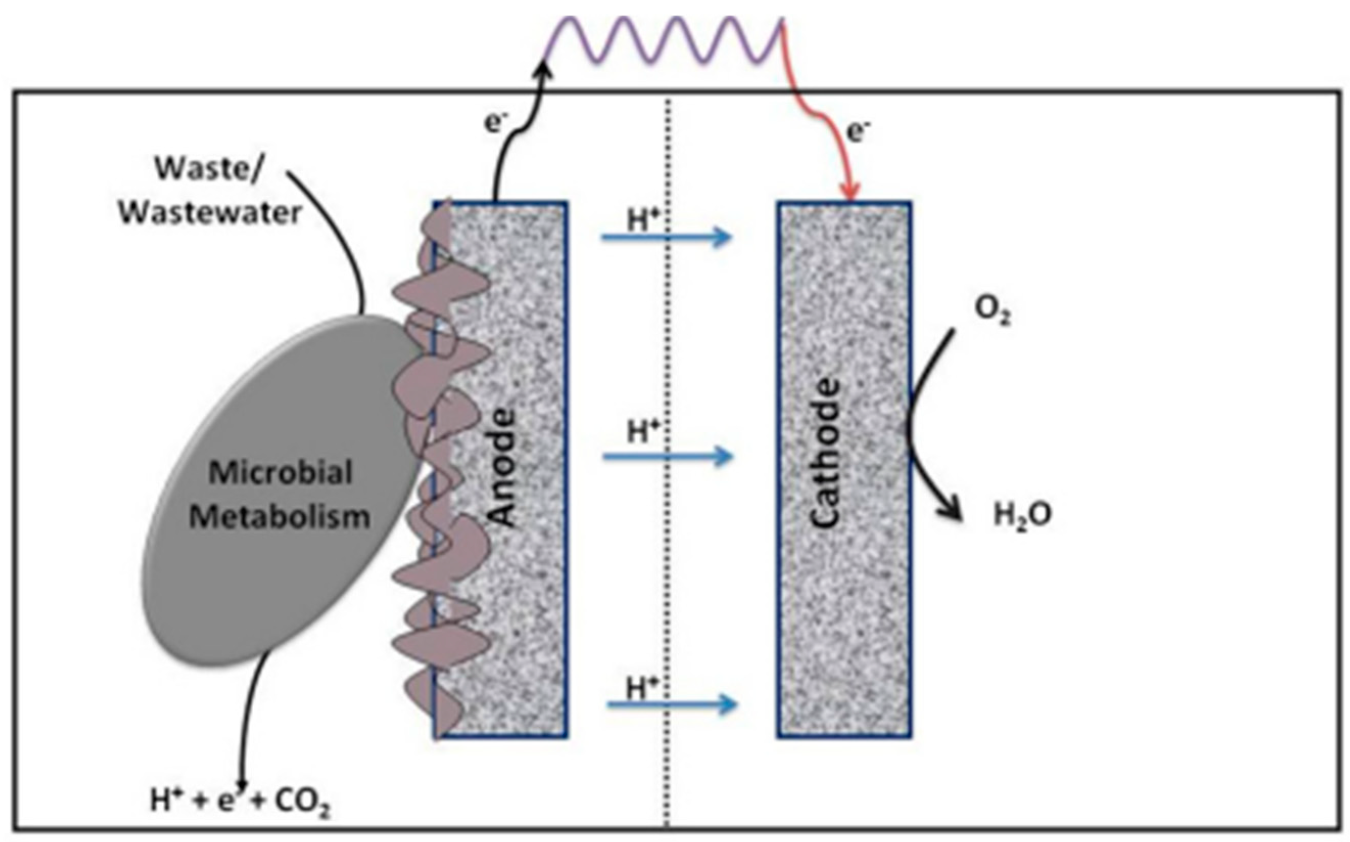
Figure 1. A generalized schematic of a microbial fuel cell showing electron release from substrate metabolism at the anode and external electron transfer [27].
Energies 17 01472 g001
Figure 2. Schematic of a microbial fuel cell with mammalian urine as the fuel stream [28].
Energies 17 01472 g002
Figure 3. Schematic of a Y-shaped MMMFC [49].
Energies 17 01472 g003
Figure 4. Schematic of microbial fuel cell with glucose substrate as a substrate [51].
Energies 17 01472 g004
Figure 5. Schematic of a microfluidic mixing system [85].
Energies 17 01472 g005
Figure 6. Schematic of the electric double layer [94].
Energies 17 01472 g006
Figure 7. Scanning electron microscope images of P. aeruginosa biofilms at (A) 72 h (3000×) and (B) 144 h (3000×) in continuous mode (Read et al., 2010) [95].
Energies 17 01472 g007
Figure 8. Structure of microbial polysaccharide [97].
Energies 17 01472 g008
Figure 9. Distribution of ions and potential associated with the electric double layer of bacteria [105]. IHP: inner Helmholtz plane; OHP: outer Helmholtz plane; ψ D : diffuse layer potential; ψ 0 : surface potential., →: Thickness of Stern and diffuse layers.
Energies 17 01472 g009
Figure 10. Schematics of the electrokinetic system. ψ is surface the potential. ζ is zeta the potential. U is the flow velocity. H is the width of the flow channel.
Energies 17 01472 g010
Figure 11. Schematic of a fibrous channel with embedded cells [68].
Energies 17 01472 g011
Figure 12. Schematic of electric double layer formation associated with bacterial cell wall (A), Geobacter cell (B). −: Deprotonated ionizable surface species of bacteria; +: Positively charged ions in aqueous solution containing organic substrates for microbial metabolism.
Energies 17 01472 g012
Figure 13. Schematic representation of the working principle of membraneless microfluidic fuel cell [173].
Energies 17 01472 g013
Figure 14. Schematic of a fibrous microfluidic channel [176].
Energies 17 01472 g014
Table 1. Ionizable surface groups in various molecular species that may be present on bacterial cell surfaces, minus the base 10 logarithm of the dissociation constants in [103].
Surface ReactionFunctional GroupNumber Density
COOH⇔–COO+H+Polysaccharide2.8
Protein, peptidoglycanBetween 4.0 and 5.0
–NH3+⇔–NH2+H+Protein, peptidoglycanBetween 9.0 and 9.8
–HPO4⇔–PO4+H+Teichoic acids2.1
–H2PO4⇔–HPO4+H+Phospholipids2.1
–HPO4⇔–PO42−+H+Phospholipids7.2
Disclaimer/Publisher’s Note: The statements, opinions and data contained in all publications are solely those of the individual author(s) and contributor(s) and not of MDPI and/or the editor(s). MDPI and/or the editor(s) disclaim responsibility for any injury to people or property resulting from any ideas, methods, instructions or products referred to in the content.