Article

Experimental Assessment of Suitability of Darrieus and Savonius Turbines for Obtaining Wind Energy from Passing Vehicles

by
Wiesław Łyskawiński
,
Krzysztof Kowalski
and
Rafał M. Wojciechowski
*
Institute of Electrical Engineering and Electronics, Faculty of Control, Robotics and Electrical Engineering, Poznan University of Technology, 60-965 Poznan, Poland
*
Author to whom correspondence should be addressed.
Energies 2024, 17(7), 1558; https://doi.org/10.3390/en17071558
Submission received: 10 February 2024 / Revised: 15 March 2024 / Accepted: 19 March 2024 / Published: 25 March 2024

Abstract

:
The article deals with the results of a comparative analysis carried out on the construction of wind turbines applied in energy generation systems using the wind of passing vehicles. The structures of turbines with horizontal and vertical axes of rotation were considered. Vertical axis wind turbines (VAWTs) have been observed to operate in various wind directions, including highly turbulent winds. Therefore, for further experimental research, VAWTs have been selected, i.e., Darrieus and Savonius turbines and their modifications. For the purpose of experimental research, the authors developed and implemented their own laboratory setup. This setup enabled the measurement of quantities such as torque, power, and power coefficient and allowed for the determination of the start-up parameters of the investigated turbines. Moreover, as part of the research, wind speed was also measured in field conditions at a distance of 1 m from the expressway. The wind speed obtained from passing vehicles did not exceed 9 m/s. For this reason, the tests of the considered turbines using the experimental setup were performed for wind speeds in the range of 5.8–8.6 m/s. The investigations were conducted based on the obtained results, and it was concluded that the helical Savonius turbine possessed the highest efficiency (0.2047 from a wind speed of 5.8 m/s) in generating energy from the wind produced by vehicles traveling on roads.

1. Introduction

In recent years, there has been a significant increase in interest in obtaining energy from renewable sources. Among the many important considerations in this regard, the most important is economic. With the right wind energy harvesting system, a significant amount of renewable electricity can be generated with zero carbon footprint. Extremely interesting are the possibilities of obtaining such energy continuously, regardless of the strength of the wind. This is made possible, among other things, by turbines driven by wind from passing vehicles [1]. The more than 2.5 billion cars on the roads around the world produce a gust of air that can be converted into electricity using small and efficient wind turbines. To harvest this energy, it is proposed that wind turbines be placed on roadsides, in the middle of divided highways, or above roadways (Figure 1).
A group of turbines placed along roadways can generate large amounts of energy, which can be used to power streetlights [2,3], illuminate signs as well as other services, or generate profits from energy sales. Due to the proximity of traffic, appropriate safety measures such as road barriers and warning signs should be used at the installation sites of such turbines. A traffic study should also be conducted to determine the viability of the wind turbine project and select the optimal solution. Moving vehicles produce intermittent and uncontrolled wind gusts depending on the volume of traffic. At night, vehicle traffic is much lower, and the demand for electricity, if only for roadway lighting, is increased. The design of such wind turbines must therefore consider energy storage and a system for efficient distribution of the energy generated. These types of wind turbines can be installed in remote locations (non-urbanized areas), forcing the construction of infrastructure to transmit electricity to the site.
Figure 1. Examples of system obtaining renewable electricity from gusts from passing cars: (a) ENLIL [4] and (b) Alpha 311 [5] turbines mounted on lampposts along highways; (c) turbines proposed by Arizona State University [6].
Energies 17 01558 g001
Very rarely, horizontal axis wind turbines (HAWTs) placed on wind stands are used to obtain energy from wind generated by moving cars. Vertical axis wind turbines (VAWTs) are much more frequently used, such as the multi-blade Banka turbine or various modifications of Savonius and Darrius turbines. Very often, energy obtained from wind is collected in energy storage facilities and then used to power road infrastructure facilities (e.g., streetlamps) along highways.
In [7], the authors conducted simulations (using a two-dimensional (2D) computational fluid dynamics model (CFD model)) of the operation of a Banka wind turbine placed on a roadside and driven by the wind gusts generated by passing cars. These authors also examined the influence of the vehicle’s speed and the distance between the vehicles and the turbine on the value of the energy generated by the VAWT. The results obtained in the study [7] indicated a decrease in the efficiency of the VAWT with an increase in the vehicle speed and an increase in the distance between the turbine and the cars. However, it should be noted that the applied 2D model significantly limits the analysis of occurring phenomena to a 2D representation, which may lead to significant calculation errors. In another work [8], Lapointe and Gopalan simulated the operating states of mini wind turbines placed above a highway using a 2D CFD model. In this work, the authors analysed phenomena occurring on a plane perpendicular to the surface. These studies were related to the analysis of a commercial helical HAWT model operating in a road lane with heavy traffic. However, the simplifications used in the work (analysis of phenomena in a two-dimensional approach) and the vehicle movement variants considered seem to differ significantly from real situations. The authors of the next paper [9] studied the amount of power generated by HAWTs mounted on overhead shafts. In this work, a dynamic analysis of air movement was carried out to obtain information regarding the optimal values for the height of turbine installation above the highway for passenger cars and trucks independently. The use of three-dimensional CFD simulation models to assess the performance of VAWTs placed in the middle lane of a highway was carried out in another publication [10]. The considerations included wind gusts generated by passenger cars and buses. Interactions occurring between moving vehicles and a wind turbine were considered in five typical variants. In turn, in [11], the results of the optimization of the Banka turbine proposed for obtaining energy from wind on a highway are presented. Among others, the following were examined: the influence of design parameters, i.e., number of blades, angle of attack curvature, and thickness and length of the blade, on the energy efficiency of the VAWT. Based on simulation calculations performed in Ansys Fluent, at a constant wind speed of 4 m/s, the optimal values of the turbine’s design parameters were determined, enabling a significant increase in their efficiency. The paper [12] deals with the results of experimental tests of a three-bladed helical VAWT designed to obtain energy from the wind of cars driving on highways. Based on the test results, it was found that the maximum value of energy generated from the wind of passing cars was obtained when the turbine was placed at a height of 1.5 m above the road. In this paper, it was also recorded that the efficiency of the turbine used was 34.6%. The authors of the next publication [13] analysed the operating states of a three-blade Darrieus wind turbine located next to a highway, using a 2D CFD model. The turbine’s performance was tested when it was acted upon by two vehicles moving in the same direction and in opposite directions, and also by one vehicle. Higher efficiency of the considered turbine was found on one-way highways compared to two-way highways. It has been noted that this condition might be due to the mutual damping of air vortices generated by vehicles moving in opposite directions. The publication [14] presented the results of three-dimensional CFD simulations and compared the operation of three different VAWTs (Darrius, Savonius, and Banka) that were placed near moving vehicles. In the based tests, the highest efficiency was obtained for the Banka turbine. Finally, in the paper [15], tests were carried out for the two types of blades used in the Savonius turbine. The influence of the height and number of blades on the power factor of the considered turbines was analysed. Simulation calculations were performed for a wind speed range of 10–20 m/s, assuming the use of these turbines on expressways. The maximum power factor equal to 0.363 was obtained for a wind speed of 15 m/s and a turbine with four rectangular blades with a height of 1.55 m. However, the wind speed range adopted in these studies seems to be too high for systems operating in the roadside strip. However, most of the cited works here considered the operation of wind turbines in roadside conditions at wind speeds in the range of 4–6 m/s [11,12]. In turn, based on the data collected in [16], it was noted that the average increase in wind speed for light vehicles and heavy goods vehicles at a wind speed of 6 m/s was 1.8 m/s and 2.4 m/s, respectively.
Wind power plants usually use permanent magnet or electromagnetically excited synchronous generators or dual-fed induction generators to convert the mechanical energy obtained from wind turbines into electricity [17]. Innovative designs like a dual-state brushless generator with dual supply are also proposed. There are no brushes or slip rings in this type of generator, which increases its reliability and lowers its operating costs compared to dual-supply induction generators [18]. In addition to this, power converters with control systems that allow for the optimization of the generated electricity are of significance [19]. However, in order to extract as much energy as possible from wind power, it is important to select the right wind turbine for a specific application. For this reason, the authors of this article decided to select and study the wind turbines best suited for harvesting the renewable wind energy generated by moving vehicles.

2. Materials and Methods

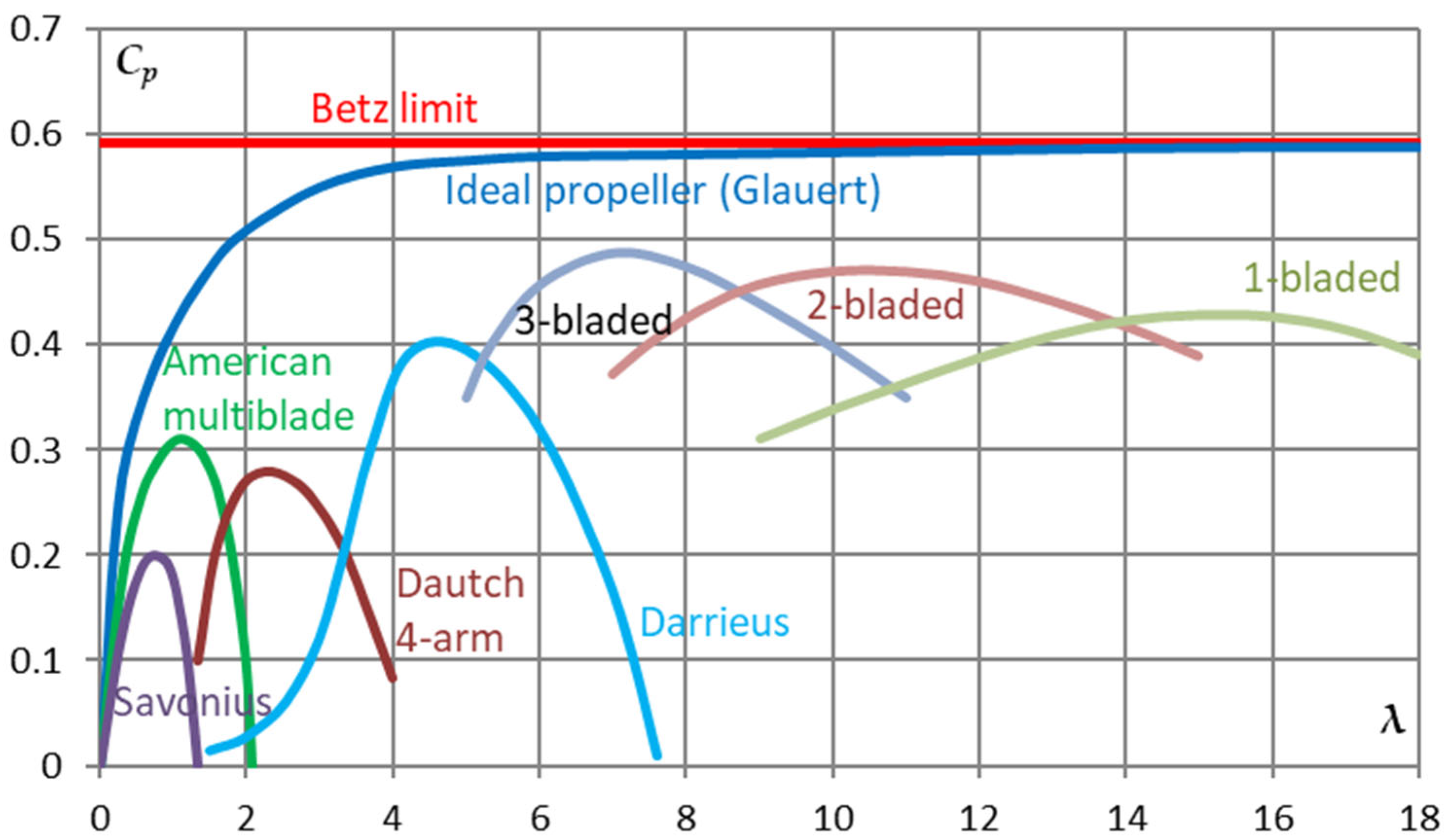
2.1. Wind Turbine Parameters

There are many wind turbine designs, with two primary solutions: horizontal axis wind turbines (HAWTs) and vertical axis wind turbines (VAWTs). One of the basic parameters characterizing a wind turbine is its power coefficient Cp:
C p = P t / P w ,
Defined as the ratio of turbine power Pt:
P t = ρ 4   A v 1 2 v 2 2 v 1 + v 2 ,
to the total wind-generated power Pw:
P w = 1 2   ρ A v 1 3 ,
with the following variables: air density (ρ), area (A) of the wind stream under consideration, and wind speed in front of the turbine (v1) and behind the turbine (v2).
After substituting (2) and (3) into relation (1), the following is obtained:
C p = 1 2 1 v 2 v 1 2 1 + v 2 v 1 ,
where Cp is also called the Betz Limit, because it was first determined by Albert Betz in 1919 [20]. By determining the extremum of this coefficient with respect to v2/v1, it is possible to calculate the optimal change in wind speed flowing through the turbine in order to obtain the greatest power from wind energy. The highest power, 16/27 of the total power carried by the wind, is obtained for (v2/v1 = 1/3) [21].
Coefficient Cp depends on the turbine’s rotational speed and instantaneous wind speed, as well as design parameters such as the number of blades and their profile, and in turbines with a horizontal axis of rotation, also on the current angle of the turbine blades [20]. Each type of wind turbine is characterized by a specific coefficient Cp. Figure 2 shows the trend of coefficient Cp versus tip-speed ratio λ—relation (5)—for a given turbine type [22,23]:
λ = 0.5 D   ω v 1 ,
where ω is the angular velocity of the turbine, and D is the diameter of the turbine.

2.2. Wind Turbine Designs

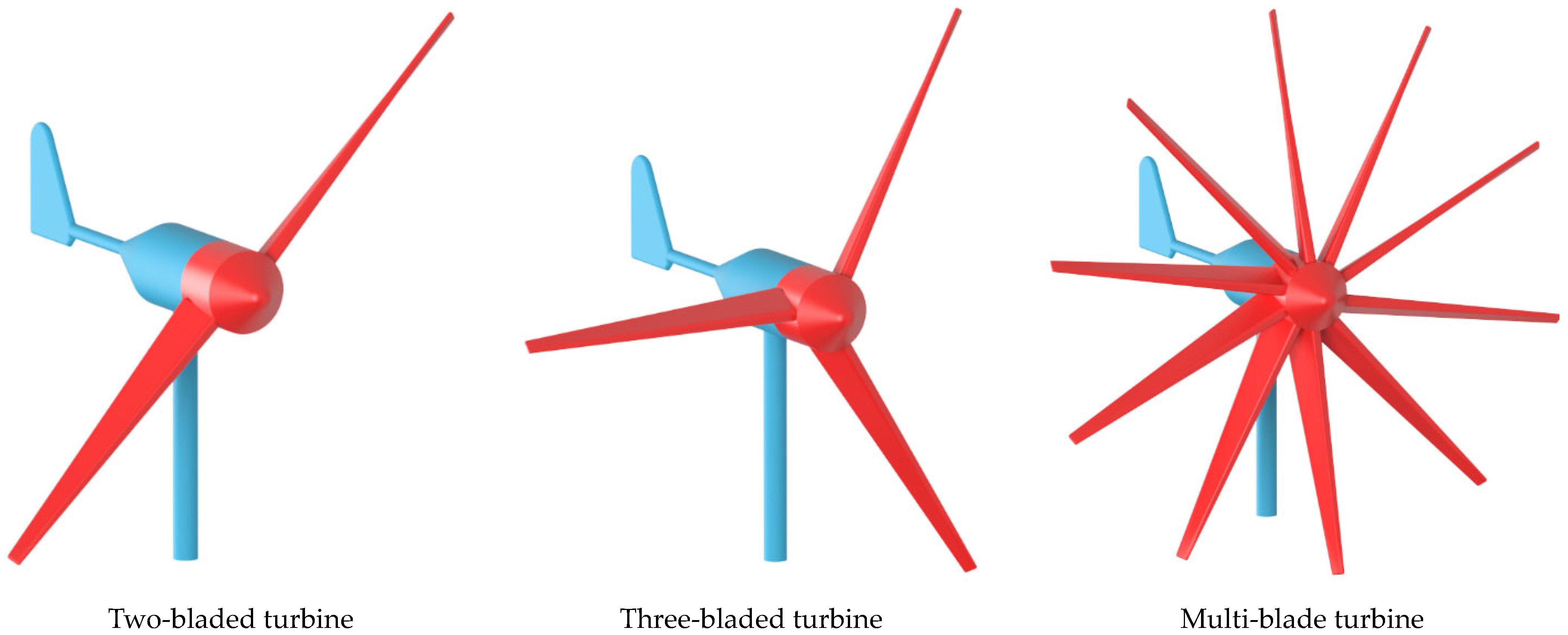
2.2.1. Horizontal Axis Wind Turbines

The Savonius turbine, with a vertical axis of rotation, has the lowest aerodynamic efficiency Cp (about 20%) [20,24]. Horizontal axis turbines (Figure 3) are now being used much more frequently, as their efficiency is higher compared to vertical axis turbines [22,25]. Three-bladed turbines [26] used in commercial wind power plants (wind farms) are the most common due to having highest wind power utilization coefficient values achieved. These turbines operate in the wind speed range from 4 to 25 m/s. Above the maximum wind value, they are turned off for structural safety reasons (large centrifugal forces could destroy the blades). These turbines can be scaled to achieve the desired output. Minor design changes are made to the blades’ geometry [27,28]. Large-capacity wind turbines use blade angle-of-attack control systems to increase the utilization of wind energy. On the other hand, single-blade, two-blade, or multi-blade solutions are almost no longer being implemented [29]. A single-blade turbine should use a counterweight to allow torque generation. Both single-blade and two-blade turbines achieve optimal operating conditions at much higher wind speeds than three-blade designs. Their advantage is lower investment costs, while a definite disadvantage is the noise they emit.
Multi-bladed turbines with at least eight blades are characterized by the use of small wind gusts, are slow-running, and have a high starting torque compared to three-bladed turbines. Their advantage, however, is quiet operation.
Turbines with a diffuser (Figure 4a) in the shape of a pipe tapering inward allow for increased efficiency in converting wind energy into mechanical energy. At the same time, they can operate at wind speeds as low as 2 m/s. The Magnus turbine (Figure 4b) replaces blades with rotating rotors. When the rotor rotates, a lifting force is generated, as well as a lateral force that causes the entire turbine to rotate. Such a turbine can operate at wind speeds of 2 to 40 m/s. Due to the much lower speed of this type of turbine (three times lower than traditional ones), there is a reduction in noise emissions. Turbines with a diffuser and using the Magnus effect are not widespread (only a few designs of this type exist).
All horizontal axis wind turbines (HAWTs) require a wind guidance system so that the wind direction is parallel to the turbine’s axis of rotation [30,31]. In addition, turbines of this type require a mechanism to limit rotation in very high winds and require sliding connections if the generator is placed in a nacelle. In addition, they can cause interference with radio, TV, and radar signals.
Figure 4. Turbine (a) with diffuser SWT-15-pro by Sylwan [32] and (b) using the Magnus effect ACOWIND A-63 (Elblag region).
Energies 17 01558 g004

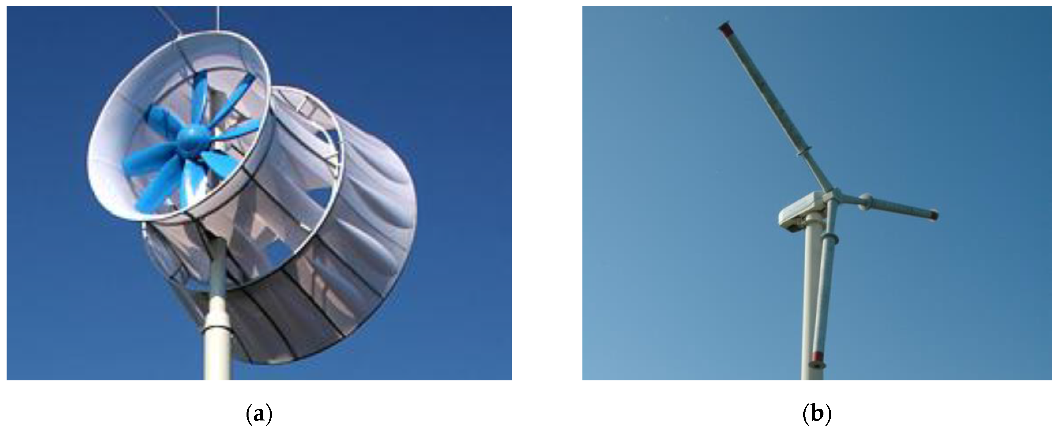
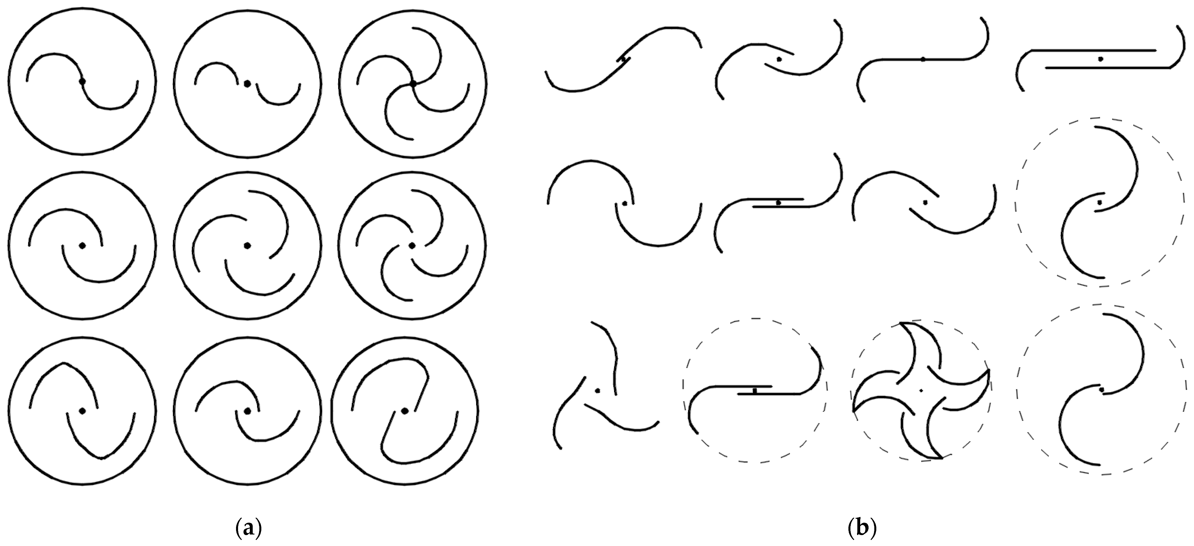
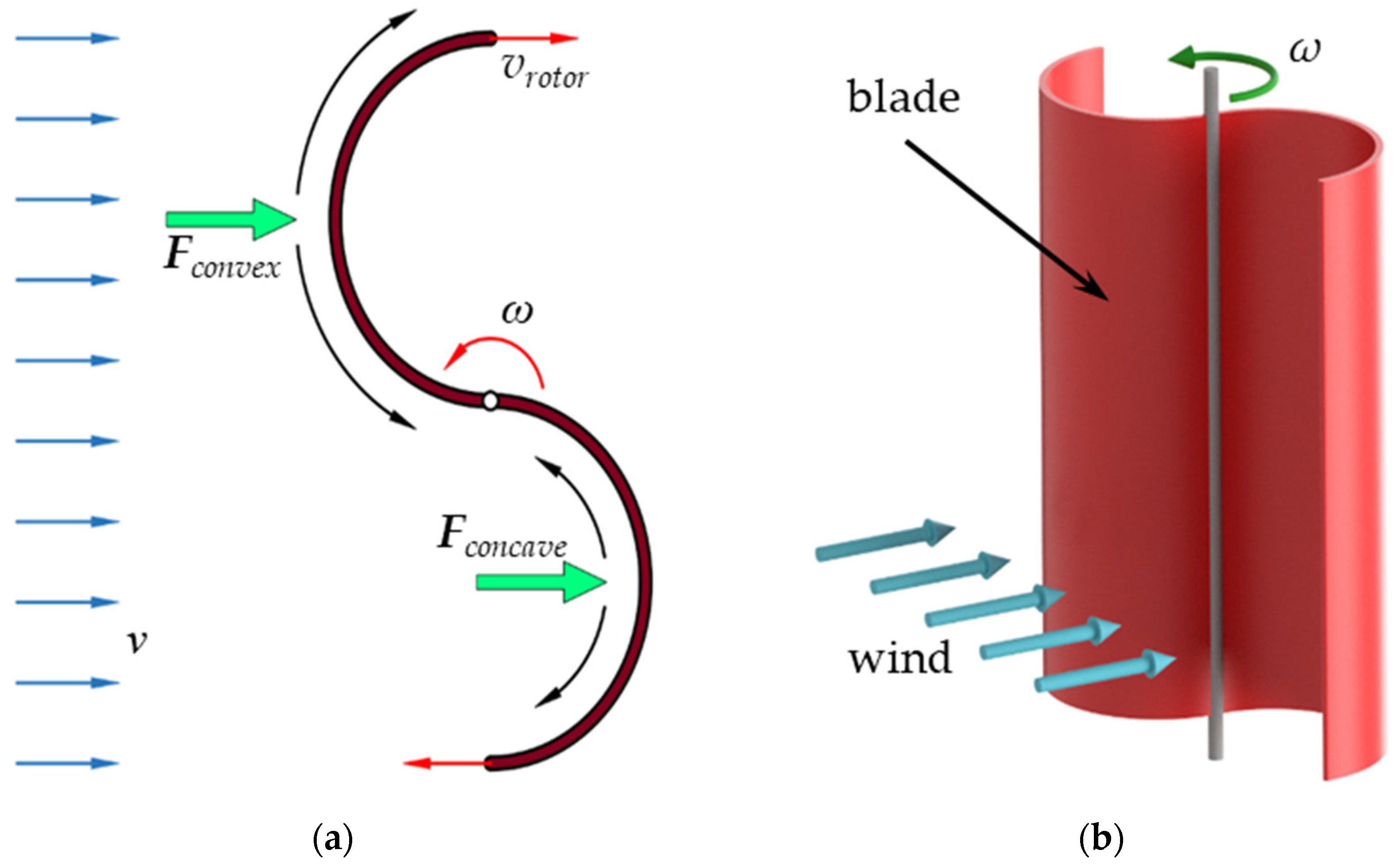
2.2.2. Vertical Axis Wind Turbines

The previously mentioned disadvantages of horizontal turbines do not occur with vertical axis wind turbines (VAWTs). The first designs of these turbines were described in the 1930s by Darrieus and Savonius [33,34]. Since those days, there has been almost no interest in developing these ideas. The blades of these turbines run much more quietly compared to HAWTs and do not require wind-setting mechanisms. The simple design of VAWTs allows them to be installed and removed quickly and avoids the use of tall masts that increase investment costs. They can be mounted on building roofs, poles, existing mast structures, etc. Unlike HAWTs, they pose no danger to birds and do not interfere with radio signals. These features provide a much broader range of applications and are driving increased interest in this type of construction. Explanations of commercial VAWT designs can be found in the literature [33,34]. The disadvantages of this type of design include, first of all, low efficiency, and because of the low speed, a slow-speed generator or gearbox must be used, reducing the efficiency of the entire system.
The turbine developed in 1922 by Finnish inventor S.J. Savonius is the simplest design with a vertical axis of rotation. There are two types of these turbines: classic and Bach model (Figure 5). In these designs, the “S” shaped blades are placed between two disks. The Savonius turbine is characterized by a low coefficient of power, but its advantages are: very simple, and therefore fail-proof, design; quiet operation over a wide range of wind force changes independent of wind direction; and high starting torque [33,35]. The principle of operation is based on the creation of a difference in aerodynamic thrust and pressures developed on individual blades due to wind flow around and inside the turbine (Figure 6). Due to their high starting torque, these turbines begin to operate at very low wind speeds, as low as 2 m/s (at very low outputs, even as low as 1.2 m/s). In contrast, the drag of blades moving “upwind” is the reason for the low wind utilization coefficient. On the other hand, however, they allow for operation at very high wind speeds of up to 56 m/s due to their self-induced braking, without the need for additional safety systems. A typical Savonius turbine has low efficiency and high variability of driving torque during rotor rotation [36]. Many research centres and wind turbine companies are working on solutions devoid of these drawbacks. A successful modification is the helical turbine [1,37,38] with a helical twist of the blades around the axis of rotation (Figure 7a). Reducing the variability of the driving torque during rotor rotation and increasing the driving torque is achieved by increasing the number of blades to five or even seven.
Due to their advantages, Savonius turbines [39] are well established. A number of blade designs [40] have been developed to improve the aerodynamic efficiency of these turbines (Figure 7).
The creator of this turbine researched more than 40 different types of turbines [41], and these ideas are being developed to modern times [42,43,44]. Figure 8 shows Savonius’ concepts [41] and contemporary solutions [45,46,47,48].
Further improvements in the performance of these turbines are possible by optimizing the shape and type of blades, along with appropriate modification of blade shape [49]. Examples of such solutions are shown in Figure 9. Arrangements of several overlapping Savonius turbines are also proposed, where the distance between them is smaller than their diameter [50].
In 1931, a turbine built with C-shaped blades connected to a shaft at their ends was patented by Frenchman G. Darrieus (Figure 10a). The entire design is characterized by high aerodynamic efficiency. Its variation is, among others, the H-type turbine (H-Darrieus, Figure 10b). The turbine uses the lifting force created by the movement of the wind around the blade profile. When the wind drives one of the blades, the other creates drag, which reduces the final speed value. The Darrieus turbine has virtually zero take-off torque and only begins operation in relatively strong winds. For this reason, it is used in conjunction with a Savonius turbine [51,52] or is accelerated with an additional electric motor. Over time, many modifications have been developed to eliminate this problem [53,54,55].
Figure 7. Turbines using drag force–different modifications: (a) helical; (b) helix wind turbine (Savonius 2.0) “with wind-catching pockets” [56]; (c) cup-bladed carousel turbine [57].
Energies 17 01558 g007
Figure 8. Modifications of Savonius turbines: (a) the author’s proposals from [41]; (b) contemporary solutions [42].
Energies 17 01558 g008
Figure 9. Savonius turbine configurations with guide vanes; (a) with a circular base, (b) with a square base.
Energies 17 01558 g009
Figure 10. Darrieus wind turbine: (a) classical, (b) H-type, (c) helical.
Energies 17 01558 g010

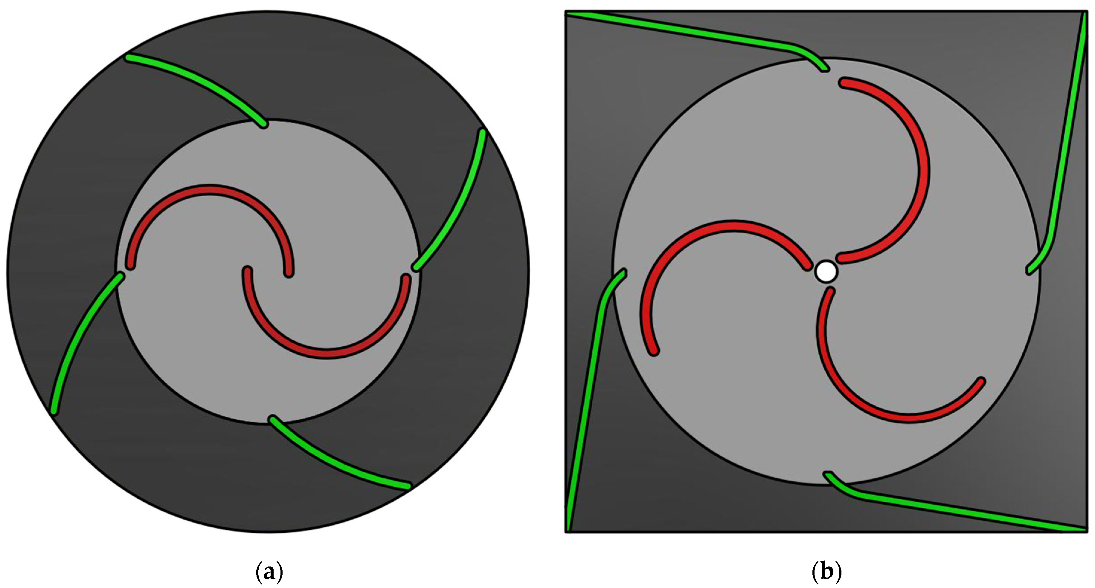
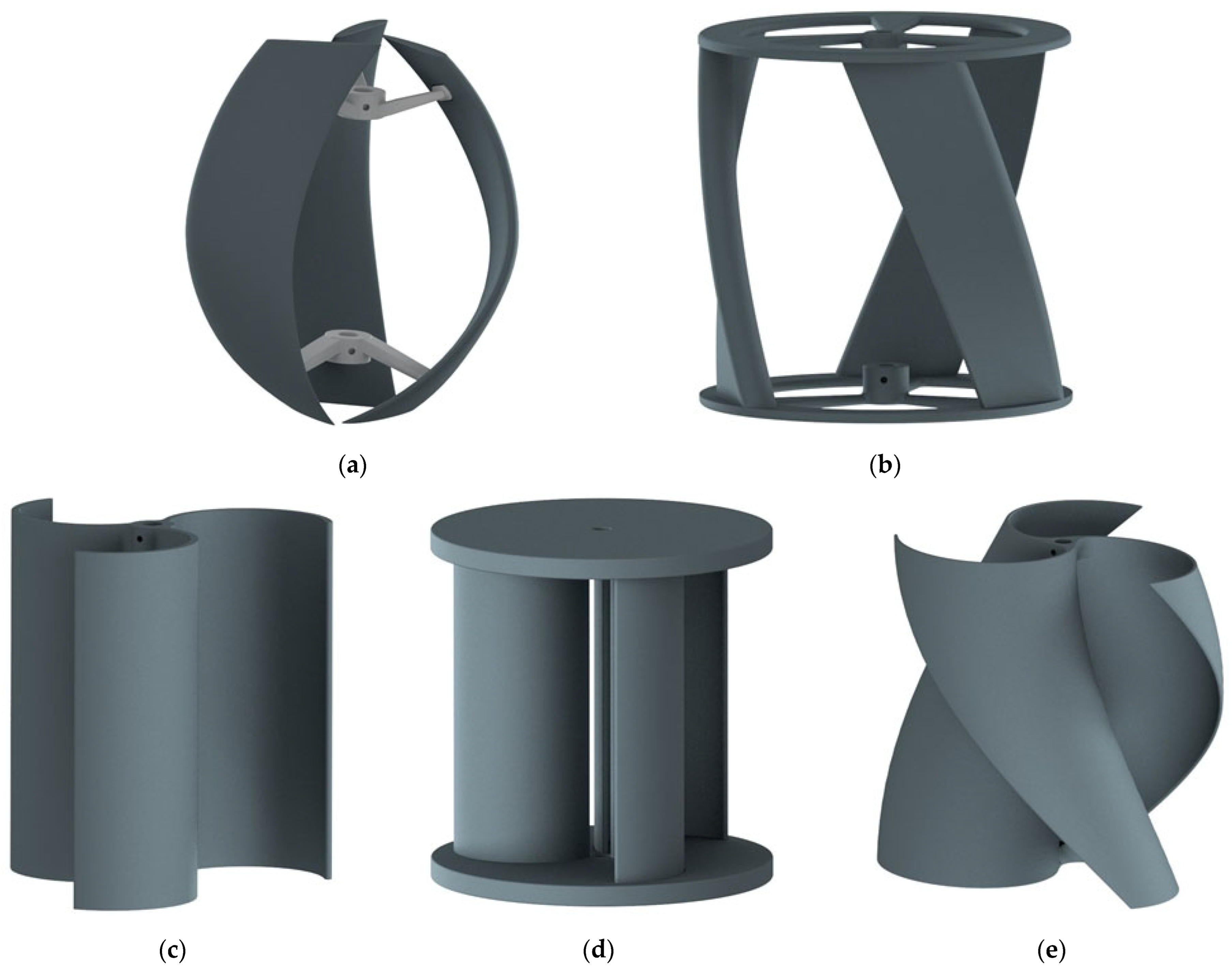
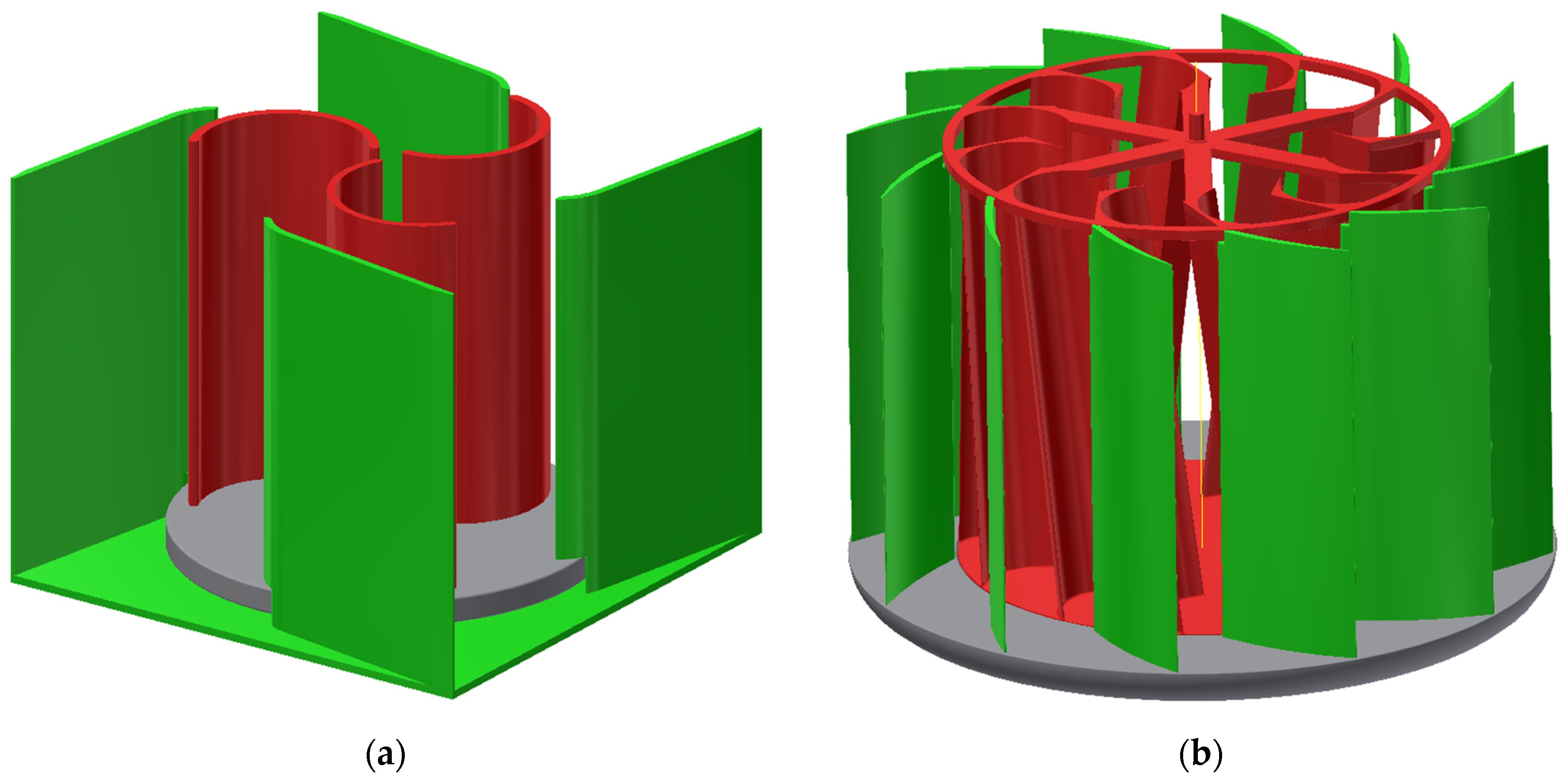
2.3. Turbine Designs Considered in Investigations

Based on their review of solutions, the authors selected 5 designs of VAWTs for acquiring renewable energy in the roadside lane with the best performance. Figure 11 shows the structures of selected turbine types (i.e., two Darrieus and three Savonius variations).

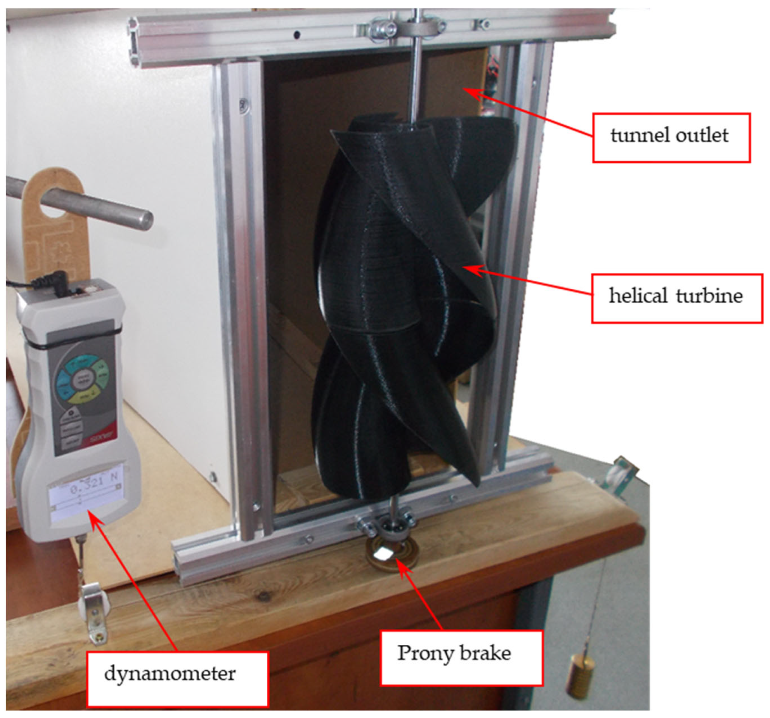
2.4. Test Stand Used in Investigations

The performed study aims to demonstrate which of the presented designs is best suited to extract renewable energy from wind gusts generated by fast-moving vehicles. The presented structures were 3D printed assuming the same dimensions for each of them (D = 140 mm, H = 140 mm). The study used a constructed tunnel (Figure 12), in which a certain wind speed was set using a fan with adjustable speed. At the outlet of this tunnel, each of these turbines was mounted to study how its speed n changes with changes in load torque T for a given constant wind speed v.
Based on the measurements (T and n) obtained, the power of the turbine was determined:
P = π   n 30   T ,
After substituting the relationship (6) describing the turbine power P into Equation (1) and taking into account the relationship (3), the power factor can be calculated from the formula:
C p = 2 P ρ A   v 3   .
Moreover, after considering ω = π   n / 30 in the Equation (5), this equation takes the form:
λ = π   n D 60   v  

3. Results

The increase in interest in the possibilities of obtaining renewable electricity from wind gusts from passing vehicles [12] has also led the authors of the submitted paper to address this research topic. Reviewing the publicly available literature, they noted that due to the multi-directional flow of the airflow as well as the strong turbulence, vertical axis wind turbines (VAWTs) should perform best in this area. Studies in this area are being carried out in many research centres [58,59]. Most often, the performance of wind turbines operating in the roadside lane is conducted based on 2D and 3D simulations using CFD models [8,10]. However, the authors of this paper decided to conduct a series of field studies related to determining the performance as well as efficiency of selected types of wind turbines.
First, they conducted studies related to determining the values of wind gust forces in the roadside lane from passing vehicles (Table 1). For this purpose, a series of wind speed measurements were carried out. The study was carried out along the S11 (Poland) expressway at a distance of 1 m from the line separating the outermost roadway lane from the roadside using BENETECH’s GM 8903 type anemometer. A view of the measurement system and applied anemometer is shown in Figure 13. The anemometer was placed at different heights relative to the roadway surface, ranging from 0.5–2 m. It was noted that for passenger cars, wind speeds above a height of 1.5 m above the roadway were characterized by lower values. This was due to the height of most passenger cars (which are generally up to 1.5 m high) and the lower airflow produced by the cars above the aforementioned height. The study was also repeated using a PCE-A 420 bucket anemometer from PCE Instruments, which allows for measurement of wind strength regardless of wind direction. Again, the results obtained were similar to those obtained with the GM 8903 BENETECH instrument (Shenzhen Jumaoyuan Science And Technology Co., Ltd., Shenzhen, China). The study was carried out on a windless day at an ambient temperature of 15 °C. In open space, the anemometer showed a wind speed close to zero. The measurements were taken between 7 a.m. and 9 a.m. during the morning traffic rush. During the measurements, the wind speeds obtained for passing vehicles were recorded at intervals of 1 s within 5-min time windows, each time recording the maximum value of wind speed for the passage of a given vehicle. The maximum wind values read for three types of vehicles (cars, delivery cars, and buses and trucks) were within the ranges given in Table 1.
The obtained results (Table 1) allowed us to determine the range of air velocities produced by passing vehicles depending on their type (height). Experimental tests of selected wind turbines were performed for several wind speeds in this range (Table 1).
At the outlet of the constructed tunnel (Figure 12), each of the selected turbines (Figure 11) was mounted in order to study how its speed changed with changes in load torque for a given constant wind speed from the range given in Table 1.
Initial studies showed Darrius turbines had major problems with starting—the start of these turbines occurred only at wind speeds above 6 m/s. The helical variety performed better in this regard (Figure 11b). A higher maximum output of no more than 300 mW at a wind speed of 8.6 m/s was also achieved for this design. Much smaller wind gusts were sufficient to run the Savonius turbines. For Bach’s two-disk design, a maximum power of nearly 800 mW was obtained at a wind speed of 8.6 m/s. It is known from the literature that the design in Figure 11c has a much better wind energy yield with the right diameter-to-height ratio (D/H = 1/2). For the above reasons, further studies were performed for three variations of the Savonius turbine starting from a diameter of 140 mm and a height of 280 mm. In the case of the design in Figure 11d, two of the same turbines offset by an angle of 60° were used to reduce the torque variation with its rotation. Figure 14 compares the obtained rotational speeds of the 3 types of Savonius turbines tested versus wind speed without shaft load (while idle). Meanwhile, the results obtained from changing the load torque of the tested turbines for several wind speeds in the range of 5.8–8.6 m/s are shown in Figure 15, Figure 16 and Figure 17.
Based on the presented characteristics, it can be concluded that while idle, a slightly higher speed is obtained with the classic Savonius turbine than with the other two turbines. The maximum power for all three turbines studied was obtained at a similar level of about 2500 mW. However, the highest torque could be applied to the helical turbine of nearly 80 Nmm at a wind speed of 8.6 m/s. This turbine also took off at a much lower speed regardless of load than the other two varieties.
For the three turbines, the dependence of coefficient of power Cp on tip-speed ratio λ was also determined (Figure 18). For the classical Savonius and Bach turbine, the highest Cp value was obtained at wind speeds of v = 6.5 m/s. At other wind speeds, the values of Cp = f (λ) were very close to each other. In contrast, for the helical Savonius turbine, the maximum Cp decreased slightly with increasing wind speed.

4. Discussion

Based on the analysis, it was found that Darrieus wind turbines have problems with starting at wind speeds below 6 m/s. This fact is also confirmed by research conducted by other research centres [14]. Although in [12] an efficiency of 0.346 was obtained for a helical Darrieus wind turbine with a structure similar to that shown in Figure 11a at a wind speed of 5 m/s, the results presented in this work may raise some doubts. The Savonius turbines and their modifications do not have problems with starting at lower wind values [60]. The research carried out in this work showed that for the three considered Savonius turbine structures, similar maximum power values were obtained in the range of 2.2–2.6 W for a wind speed of 8.6 m/s. However, it was also noted that the helical Savonius wind turbine (Figure 11e) provides more than twice as much torque as the Bach turbine (Figure 11c) or the classic Savonius turbine (Figure 11d). This allows for easier starting of this turbine even at low wind speeds. For the tested turbines, it seems that the turbine in Figure 11e (i.e., helical Savonius) is best suited for obtaining energy from wind generated by passenger cars. This turbine is also characterized by a higher efficiency value reaching over 20% (at a wind speed of 5.8 m/s) than the other two structures whose efficiency did not exceed 18%.

5. Conclusions

This study has shown that the most favourable turbine for harvesting energy from wind gusts caused by passing vehicles is the helical turbine. This turbine features high starting torque and starts at low wind speeds even with a load. Due to its design, the driving torque generated is uniform around the entire rotation of the turbine. To increase its efficiency, guide vanes (Figure 19a) can be used to shield part of the blades working against the wind and increase the speed of the airflow acting on the driving blades. The authors intend to carry out this type of testing on a constructed stand. An interesting option seems to be the Banks [11,61,62] multi-bladed wind turbine, characterized by good efficiency in extracting energy from high turbulence winds. A similar turbine design with blades was proposed by Pawlak [63]. A similar wind turbine design is also intended to be studied by the authors of this publication (Figure 19b). The authors plan to report the results of further research obtained in this area in their next works.

Author Contributions

Conceptualization, W.Ł., K.K. and R.M.W.; methodology, W.Ł. and R.M.W.; investigation, W.Ł. and K.K.; resources, R.M.W. and K.K.; data curation, W.Ł.; writing—original draft preparation, W.Ł. and K.K.; writing—review and editing, R.M.W.; visualization, K.K. and W.Ł.; project administration, W.Ł. All authors have read and agreed to the published version of the manuscript.

Funding

This research was funded by Rector’s Grant of Poznan University of Technology about number of 0212/SIGR/2581.

Data Availability Statement

Data is contained within the article.

Conflicts of Interest

The authors declare no conflicts of interest.

References

  1. Kamoji, M.A.; Kedare, S.B.; Prabhu, S.V. Performance Tests on Helical Savonius Rotors. Renew. Energy 2009, 34, 521–529. [Google Scholar] [CrossRef]
  2. Ricci, R.; Romagnoli, R.; Montelpare, S.; Vitali, D. Experimental Study on a Savonius Wind Rotor for Street Lighting Systems. Appl. Energy 2016, 161, 143–152. [Google Scholar] [CrossRef]
  3. Sundaram, A.; Almobasher, L. Implementation of a Highway Wind Power Generation Using Vertical Axis Wind Turbine to Automatically Power a Street Lamp. Wind. Eng. 2020, 45, 1176–1192. [Google Scholar] [CrossRef]
  4. ENLIL Vertical Axis Wind Turbine|Smart City. Available online: http://okosvaros.lechnerkozpont.hu/en/node/703 (accessed on 2 February 2024).
  5. Wind Turbines Attached to Lamp Posts Generate Electricity via Traffic. Available online: https://www.intelligentliving.co/wind-turbines-lamp-posts/ (accessed on 2 February 2024).
  6. Student Design Turns Highways into Wind Farms. Available online: https://inhabitat.com/student-designs-highway-power/ (accessed on 2 February 2024).
  7. Tian, W.; Mao, Z.; Li, Y. Numerical Simulations of a VAWT in the Wake of a Moving Car. Energies 2017, 10, 478. [Google Scholar] [CrossRef]
  8. Lapointe, C.; Gopalan, H. Numerical Investigation of Mini Wind Turbines Near Highways. J. Sol. Energy Eng. 2016, 138, 024503. [Google Scholar] [CrossRef]
  9. Hegde, S.S.; Thamban, A.; Bhai, S.P.M.; Ahmed, A.; Upadhyay, M.; Joishy, A.; Mahalingam, A. Highway Mounted Horizontal Axial Flow Turbines For Wind Energy Harvesting From Cruising Vehicles. In Proceedings of the ASME 2016 International Mechanical Engineering Congress and Exposition, Phoenix, AZ, USA, 14 November 2016; pp. 1–9. [Google Scholar]
  10. Tian, W.; Mao, Z.; An, X.; Zhang, B.; Wen, H. Numerical Study of Energy Recovery from the Wakes of Moving Vehicles on Highways by Using a Vertical Axis Wind Turbine. Energy 2017, 141, 715–728. [Google Scholar] [CrossRef]
  11. Lee, O.; Baby, D. Optimising Highway Energy Harvesting: A Numerical Simulation Study on Factors Influencing the Performance of Vertical-Axis Wind Turbines. Energies 2023, 16, 7245. [Google Scholar] [CrossRef]
  12. Bani-Hani, E.H.; Sedaghat, A.; AL-Shemmary, M.; Hussain, A.; Alshaieb, A.; Kakoli, H. Feasibility of Highway Energy Harvesting Using a Vertical Axis Wind Turbine. Energy Eng. 2018, 115, 61–74. [Google Scholar] [CrossRef]
  13. Toudarbari, S.; Maghrebi, M.; Hashemzadeh, A. Evaluation of Darrieus Wind Turbine for Different Highway Settings Using CFD Simulation. Sustain. Energy Technol. Assess. 2021, 45, 101077. [Google Scholar] [CrossRef]
  14. Tian, W.; Song, B.; Mao, Z. Numerical Investigation of Wind Turbines and Turbine Arrays on Highways. Renew. Energy 2020, 147, 384–398. [Google Scholar] [CrossRef]
  15. Hu, W.; E, J.; Deng, Y.; Li, L.; Han, D.; Zhao, X.; Zhang, Z.; Peng, Q. Effect Analysis on Power Coefficient Enhancement of a Convective Wind Energy Collecting Device in the Expressway. Energy Convers. Manag. 2018, 171, 249–271. [Google Scholar] [CrossRef]
  16. Venkatesh, P.; Babu, A.R.V.; Suresh, K. Experimental Investigations on Modified Savonius Wind Turbine with Curtain Arrangements in the Middle of the Highway. Eur. J. Electr. Eng. 2018, 20, 139–150. [Google Scholar] [CrossRef]
  17. Michna, M.; Blecharz, K.; Kostro, G.; Kutt, F.; Ryndzionek, R. Development and Performance Analysis of a Novel Multiphase Doubly-Fed Induction Generator. Arch. Electr. Eng. 2022, 71, 1003–1015. [Google Scholar] [CrossRef]
  18. Bai, C.; Song, Y.; He, G.; Yin, X.; Liu, H. A Dual-Stator Brushless Doubly-Fed Generator for Wind Power Application. Arch. Electr. Eng. 2023, 72, 1073–1087. [Google Scholar] [CrossRef]
  19. Jabal Laafou, A.; Abdessalam, A.M.; Addaim, A.; Moumani, Y. A Comparative Study Based on Proportional Integral and Backstepping Controllers for Doubly Fed Induction Generator Used in Wind Energy Conversion System. Arch. Electr. Eng. 2023, 72, 211–228. [Google Scholar] [CrossRef]
  20. Betz, A. Introduction to the Theory of Flow Machines; Pergamon Press: Oxford, UK, 1966. [Google Scholar]
  21. Ragheb, M.; Ragheb, A.M. Wind Turbines Theory-The Betz Equation and Optimal Rotor Tip Speed Ratio. In Fundamental and Advanced Topics in Wind Power; IntechOpen: London, UK, 2011; ISBN 978-953-307-508-2. [Google Scholar]
  22. Hau, E. Wind Turbines: Fundamentals, Technologies, Application, Economics; Springer Science & Business Media: Berlin/Heidelberg, Germany, 2013; ISBN 978-3-642-27151-9. [Google Scholar]
  23. Castillo, O.C.; Andrade, V.R.; Rivas, J.J.R.; González, R.O. Comparison of Power Coefficients in Wind Turbines Considering the Tip Speed Ratio and Blade Pitch Angle. Energies 2023, 16, 2774. [Google Scholar] [CrossRef]
  24. Manwell, J.F.; McGowan, J.G.; Rogers, A.L. Wind Energy Explained: Theory, Design and Application; John Wiley & Sons: Hoboken, NJ, USA, 2010; ISBN 978-0-470-68628-7. [Google Scholar]
  25. Eriksson, S.; Bernhoff, H.; Leijon, M. Evaluation of Different Turbine Concepts for Wind Power. Renew. Sustain. Energy Rev. 2008, 12, 1419–1434. [Google Scholar] [CrossRef]
  26. Schubel, P.J.; Crossley, R.J. Wind Turbine Blade Design Review. Wind. Eng. 2012, 36, 365–388. [Google Scholar] [CrossRef]
  27. Bazilevs, Y.; Hsu, M.-C.; Akkerman, I.; Wright, S.; Takizawa, K.; Henicke, B.; Spielman, T.; Tezduyar, T.E. 3D Simulation of Wind Turbine Rotors at Full Scale. Part I: Geometry Modeling and Aerodynamics. Int. J. Numer. Methods Fluids 2011, 65, 207–235. [Google Scholar] [CrossRef]
  28. Hansen, M. Aerodynamics of Wind Turbines, 3rd ed.; Routledge: London, UK, 2015; ISBN 978-1-315-76998-1. [Google Scholar]
  29. Spera, D.A. Wind Turbine Technology: Fundamental Concepts of Wind Turbine Engineering; ASME Press: New York, NY, USA, 2009; ISBN 978-0-7918-0260-1. [Google Scholar]
  30. Bertagnolio, F.; Sørensen, N.; Johansen, J.; Fuglsang, P. Wind Turbine Airfoil Catalogue; Riso National Laboratory: Roskilde, Denmark, 2001. [Google Scholar]
  31. Hansen, M.O.L. Aerodynamics of Wind Turbines: Rotors, Loads and Structure; James & James Ltd.: London, UK, 2000; ISBN 1-902916-06-9. [Google Scholar]
  32. Innovative Technology SYLWAN Company. SWT-Smart Wind Turbine. Diffuser Wind Turbine. Available online: https://docplayer.pl/6154845-Innowacyjna-technologia-zastosowanie-dyfuzora-swt-smart-wind-turbine-dyfuzorowa-turbina-wiatrowa-samoczynnie-pod-wiatr.html (accessed on 2 February 2024). (In Polish).
  33. Savonius, S.J. The S-Rotor and Its Applications. Mech. Eng. 1931, 53, 333–338. [Google Scholar]
  34. Darrieus, G.J. Turbine Having Its Rotating Shaft Transverse to the Flow of the Current. U.S. Patent 1,835,018, 8 December 1931. [Google Scholar]
  35. Wagner, H.-J.; Mathur, J. Introduction to Wind Energy Systems: Basics, Technology and Operation, 2nd ed.; Springer: Berlin/Heidelberg, Germany, 2014; ISBN 978-3-642-44812-6. [Google Scholar]
  36. Sobczak, K.; Obidowski, D.; Reorowicz, P.; Marchewka, E. Numerical Investigations of the Savonius Turbine with Deformable Blades. Energies 2020, 13, 3717. [Google Scholar] [CrossRef]
  37. Damak, A.; Driss, Z.; Abid, M.S. Experimental Investigation of Helical Savonius Rotor with a Twist of 180°. Renew. Energy 2013, 52, 136–142. [Google Scholar] [CrossRef]
  38. Mendoza, V.; Katsidoniotaki, E.; Bernhoff, H. Numerical Study of a Novel Concept for Manufacturing Savonius Turbines with Twisted Blades. Energies 2020, 13, 1874. [Google Scholar] [CrossRef]
  39. Abraham, J.P.; Plourde, B.D.; Mowry, G.S.; Minkowycz, W.J.; Sparrow, E.M. Summary of Savonius Wind Turbine Development and Future Applications for Small-Scale Power Generation. J. Renew. Sustain. Energy 2012, 4, 042703. [Google Scholar] [CrossRef]
  40. Tian, W.; Song, B.; VanZwieten, J.H.; Pyakurel, P. Computational Fluid Dynamics Prediction of a Modified Savonius Wind Turbine with Novel Blade Shapes. Energies 2015, 8, 7915–7929. [Google Scholar] [CrossRef]
  41. Savonius, S.J. The Wing-Rotor in Theory and Practice; Savonius and Co.: Helsingfors, Finland, 1925. [Google Scholar]
  42. Zemamou, M.; Aggour, M.; Toumi, A. Review of Savonius Wind Turbine Design and Performance. Energy Procedia 2017, 141, 383–388. [Google Scholar] [CrossRef]
  43. Mahmoud, N.H.; El-Haroun, A.A.; Wahba, E.; Nasef, M.H. An Experimental Study on Improvement of Savonius Rotor Performance. Alex. Eng. J. 2012, 51, 19–25. [Google Scholar] [CrossRef]
  44. Norouztabar, R.; Mousavi Ajarostaghi, S.S.; Mousavi, S.S.; Nejat, P.; Rahimian Koloor, S.S.; Eldessouki, M. On the Performance of a Modified Triple Stack Blade Savonius Wind Turbine as a Function of Geometrical Parameters. Sustainability 2022, 14, 9816. [Google Scholar] [CrossRef]
  45. Alom, N.; Saha, U.K. Four Decades of Research Into the Augmentation Techniques of Savonius Wind Turbine Rotor. J. Energy Resour. Technol. 2018, 140, 050801. [Google Scholar] [CrossRef]
  46. Anwar, K.; Himran, S.; Sule, L.; Azis, N. Numerical Investigation of Modified Savonius Wind Turbine with Various Straight Blade Angle. J. Mech. Eng. Res. Dev. 2018, 41, 38–42. [Google Scholar] [CrossRef]
  47. Scheaua, F.; Goanta, A.; Dragan, N. Review of Specific Performance Parameters of Vertical Wind Turbine Rotors Based on the SAVONIUS Type. Energies 2021, 14, 1962. [Google Scholar] [CrossRef]
  48. Kacprzak, K.; Liskiewicz, G.; Sobczak, K. Numerical Investigation of Conventional and Modified Savonius Wind Turbines. Renew. Energy 2013, 60, 578–585. [Google Scholar] [CrossRef]
  49. Rahai, H.; Beach, L. Development of Optimum Design Configuration and Performance for Vertical Axis Wind Turbine; California State University: Long Beach, CA, USA, 2005. [Google Scholar]
  50. Tian, W.; Ni, X.; Mao, Z.; Wang, Y.-F. Study on the Performance of a New VAWT with Overlapped Side-by-Side Savonius Rotors. Energy Convers. Manag. 2022, 264, 115746. [Google Scholar] [CrossRef]
  51. Pallotta, A.; Pietrogiacomi, D.; Romano, G.P. HYBRI—A Combined Savonius-Darrieus Wind Turbine: Performances and Flow Fields. Energy 2020, 191, 116433. [Google Scholar] [CrossRef]
  52. Anjum, Z.; Najmi, L.A.; Fahad, A.; Ashraf, R.; Ehsan, S.; Aslam, W. Common Vertical Axis Savonius-Darrieus Wind Turbines for Low Wind Speed Highway Applications. Tech. J. Univ. Eng. Technol. (UET) Taxila Pak. 2016, 21, 85–90. [Google Scholar]
  53. Zamani, M.; Maghrebi, M.J.; Varedi, S.R. Starting Torque Improvement Using J-Shaped Straight-Bladed Darrieus Vertical Axis Wind Turbine by Means of Numerical Simulation. Renew. Energy 2016, 95, 109–126. [Google Scholar] [CrossRef]
  54. Mohan Kumar, P.; Sivalingam, K.; Lim, T.-C.; Ramakrishna, S.; Wei, H. Strategies for Enhancing the Low Wind Speed Performance of H-Darrieus Wind Turbine—Part 1. Clean Technol. 2019, 1, 185–204. [Google Scholar] [CrossRef]
  55. Kumar, P.M.; Sivalingam, K.; Narasimalu, S.; Lim, T.-C.; Ramakrishna, S.; Wei, H. A Review on the Evolution of Darrieus Vertical Axis Wind Turbine: Small Wind Turbines. J. Power Energy Eng. 2019, 7, 27–44. [Google Scholar] [CrossRef]
  56. Gipe, P. Wind Energy Basics: A Guide to Home and Community-Scale Wind-Energy Systems, 2nd ed.; Chelsea Green Publishing: Chelsea, VT, USA, 2009; ISBN 978-1-60358-227-8. [Google Scholar]
  57. Anweiler, S.; Fedak, W.; Gancarski, W.; Ulbrich, R. Power Spectrum Analysis for Determination of the Number of Vertical Axis Wind Turbine Blades. J. Mech. Energy Eng. 2017, 41, 153–162. [Google Scholar]
  58. Santhakumar, S.; Palanivel, I.; Venkatasubramanian, K. A Study on the Rotational Behaviour of a Savonius Wind Turbine in Low Rise Highways during Different Monsoons. Energy Sustain. Dev. 2017, 40, 1–10. [Google Scholar] [CrossRef]
  59. Sayais, S.Y.; Salunkhe, G.P.; Patil, P.G.; Khatik, M.F. Power Generation on Highway by Using Vertical Axis Wind Turbine & Solar System. Int. Res. J. Eng. Technol. 2018, 5, 2133–2137. [Google Scholar]
  60. Lipiao, J.A.C.; Divina, N.M.M.; Santiago, R.V.M.; Hortinela, C.C. Hybrid J-Type Darrieus and Savonius Vertical Axis Wind Turbine Capable of Harvesting Roadside Wind Energy. In Proceedings of the 11th International Conference on Renewable Energy Research and Application (ICRERA), Istanbul, Turkey, 18 September 2022; pp. 1–6. [Google Scholar]
  61. Matias, I.J.T.; Danao, L.A.M.; Abuan, B.E. Numerical Investigation on the Effects of Varying the Arc Length of a Windshield on the Performance of a Highway Installed Banki Wind Turbine. Fluids 2021, 6, 285. [Google Scholar] [CrossRef]
  62. Ismaeel, T.; Aljabair, S.; Abdulrazzaq, O.; Abood, Y. Energy Recovery of Moving Vehicles’ Wakes in Highways by Vertical Axis Wind Turbines. FME Trans. 2020, 48, 557–565. [Google Scholar] [CrossRef]
  63. Pawlak, Z. Compact Double-Stage Fluid Flow Turbine. PL Patent No. 208206, 18 August 2010. (In Polish). [Google Scholar]
Figure 2. Power coefficient Cp versus tip-speed ratio λ for different type of wind turbines.
Energies 17 01558 g002
Figure 3. Horizontal axis wind turbines.
Energies 17 01558 g003
Figure 5. Savonius turbines: (a) classical; (b) Bach model.
Energies 17 01558 g005
Figure 6. Savonius turbine aerodynamics: (a) view of cross-section and (b) 3D view.
Energies 17 01558 g006
Figure 11. Studied turbine types: Darrius (a) classical, (b) helical and Savonius, (c) Bach model, (d) classical, (e) helical.
Energies 17 01558 g011
Figure 12. Test stand for the wind turbines under consideration.
Energies 17 01558 g012
Figure 13. Wind speed measurement on the S11 expressway in Poland: (a) measurement system, (b) anemometer GM 8903 BENETECH.
Energies 17 01558 g013
Figure 14. Rotational speed versus wind speed for turbines: Bach model (Figure 11c), classic Savonius (Figure 11d) and helical Savonius (Figure 11e).
Energies 17 01558 g014
Figure 15. Characteristics of (a) torque and (b) power as a function of the rotational speed of the Bach turbine.
Energies 17 01558 g015
Figure 16. Characteristics of (a) torque and (b) power as a function of the rotational speed of the Savonius turbine.
Energies 17 01558 g016
Figure 17. Characteristics of (a) torque and (b) power as a function of the rotational speed of the helical Savonius turbine.
Energies 17 01558 g017
Figure 18. Power coefficient Cp versus tip-speed ratio λ for (a) Savonius and Bach turbines at v = 6.5 m/s and (b) helical Savonius turbine.
Energies 17 01558 g018
Figure 19. Turbines with guide vanes: (a) Savonius and (b) multi-blade.
Energies 17 01558 g019
Table 1. Measurement of wind speed from moving vehicles at a speed of 80–90 km/h at a distance of 1 m from the boundary line of the far right lane of the S11 expressway.
Vehicle TypeWind Speed (m/s)
buses and trucks4.5–8.9
delivery cars3.2–6.7
cars2.1–4.6
Disclaimer/Publisher’s Note: The statements, opinions and data contained in all publications are solely those of the individual author(s) and contributor(s) and not of MDPI and/or the editor(s). MDPI and/or the editor(s) disclaim responsibility for any injury to people or property resulting from any ideas, methods, instructions or products referred to in the content.

