Communication

A Two-Dimensional Heterostructured Covalent Organic Framework/Graphene Composite for Stabilizing Lithium–Sulfur Batteries

Jiangsu Key Laboratory of Electrochemical Energy-Storage Technologies, College of Materials Science and Technology, Nanjing University of Aeronautics and Astronautics, Nanjing 210016, China
*
Author to whom correspondence should be addressed.
Energies 2024, 17(7), 1559; https://doi.org/10.3390/en17071559
Submission received: 6 January 2024 / Revised: 5 March 2024 / Accepted: 18 March 2024 / Published: 25 March 2024
(This article belongs to the Section D1: Advanced Energy Materials)

Abstract

:
The implementation of a functional separator represents a highly encouraging approach to mitigating polysulfide shuttling in lithium–sulfur (Li–S). In this study, a two-dimensional (2D) 1,3,5-triformylphloroglucinol (Tp)-p-phenylenediamine (Pa) covalent organic framework/reduced graphene oxide (rGO) functional layer was introduced to enhance the performance of the commercial separator in Li–S batteries. The resulting 2D TpPa@rGO modified separators exhibit significantly improved electronic and ionic conductivity when compared to the unmodified separator, effectively mitigating lithium polysulfide shuttling and enhancing sulfur cathode utilization. It is indicated that a heterostructured composite of a nitrogen-group-containing COF and an electronic conductive addictive is an effective modification to the separator. Consequently, the modified cell demonstrated a minimal degradation rate of only 0.12% per cycle over 350 cycles at 0.5 C.

1. Introduction

Lithium–sulfur (Li–S) batteries not only offer a high theoretical specific capacity and energy density but also present advantages such as cost-effectiveness and environmental friendliness in their sulfur cathode [1,2]. Nevertheless, there remain several challenges that impede their widespread commercialization, including capacity degradation and severe self-discharge. These challenges encompass the low electronic/ionic conductivity of sulfur and its reaction product (Li2S) and the loss of active material caused by the “shuttle effect” of the dissolved lithium polysulfide (Li2Sx, 4 ≤ x ≤ 8) intermediates [3,4,5]. To tackle these aforementioned challenges, the incorporation of a functional interlayer between the sulfur cathode and the conventional commercial separator has demonstrated efficacy in mitigating the “shuttle effect” of polysulfide intermediates, consequently enhancing the cycling performance of Li–S batteries. A typical method is to modify the conventional separator with functional materials [6,7,8]. The coating materials should possess high electronic conductivity to facilitate electron transport. On the other hand, the surface area should be large enough to provide sites for the chemical adsorption of polysulfides. Furthermore, the materials should possess high stability so that they will not be dissolved in the electrolyte. Carbon, polymer, metal oxides, sulfide, etc., have been used [9,10]. However, each of these examples has its own advantages and considerations. For example, carbon possesses a high surface area and electronic conductivity. Nevertheless, the functional group on carbon is poor, which cannot provide a strong affinity to the polysulfides [11,12]. It is important to develop improved coating materials to address the limitations of Li–S batteries.
Covalent organic frameworks (COFs) are porous crystalline organic polymer materials known for their low density, substantial specific surface area, tunable pores, and versatile design and functionalization capabilities [13,14]. These features enable selective Li+ conduction while minimizing the adverse effects of polysulfide shuttling and have garnered increasing attention for modifying separators for Li–S batteries in recent years [15,16,17]. For example, by using 1,4-phenylenediamine-2-sulfonic acid (Pa-SO3H) and 1,3,5-triformylphloroglucinol (Tp) as precursors, Cao et al. synthesized imide-based COF (TpPa-SO3H) nanosheets through interfacial synthesis. They subsequently converted TpPa-SO3H into TpPa-SO3Li via ion exchange and produced TpPa-SO3Li/Celgard separators through vacuum filtration. The TpPa-SO3Li COF layer possesses aligned nano-channels and negatively charged sites, which effectively facilitate Li+ transport and significantly impede polysulfide shuttling [17]. Nevertheless, in the context of advanced separator coatings for Li–S batteries, it is crucial to consider achieving more precise control over the porosity and improved electron/ion conductivity of the COFs. The optimal coatings should possess an appropriate thickness and an extensive surface coverage while not compromising the overall energy density of the Li–S batteries [15]. Several methods have been reported for comparing few-layered COFs, such as interfacial polymerization, gas-phase polymerization, and chemical/physical exfoliation. However, developing few-layered COF materials for Li–S batteries is a challenge in terms of scale and controllable preparation.
In recent years, heterostructures have emerged as a significant development, leveraging the strengths of two-component materials to achieve a synergistic effect greater than the sum of their individual contributions [11,18]. Combining polymers with carbon materials, focusing on improving the adsorption ability and electrical conductivity, can synergistically improve the chemical confinement and polysulfide conversion for advanced performance. Based on this, constructing a heterostructure is an extremely effective method, which can thereby simultaneously realize the advantages of achieving fast redox reaction kinetics and long-term stability for Li–S batteries [19,20]. In this work, we prepared a two-dimensional (2D) heterostructured TpPa@rGO composite as the functional interlayer for Li–S batteries. The 2D heterostructured TpPa@rGO offers robust chemisorption sites for effective polysulfide capture. Additionally, rGO exhibits an outstanding electrical conductivity, enabling the efficient utilization of sulfur. As a result, Li–S cells with a TpPa@rGO interlayer exhibited high specific capacities and long-term cycling stabilities. This work may provide some new insights into the rational design of a novel heterostructured modification layer on a separator and provide new insights into developing and opportunities to develop advanced Li–S batteries.

2. Experimental Section

2.1. Material Synthesis

Synthesis of TpPa-COF: A total of 0.45 mmol p-phenylenediamine (Pa) and 500 mg 1,3,5-triformylphloroglucinol (Tp) was dispersed into 4 mL of deionized water using ultrasound. Then, 0.3 mmol Tp was added and shaken for 20 min. The mixture was transferred into an autoclave and kept in an oven at 150 °C for 48 h. The product was washed using water 3 times and subsequently with acetone using Soxhlet extraction and then dried overnight at 60 °C.
Synthesis of the TpPa@rGO composite: A total of 16.2 mg Pa and 166.6 mg PTSA was dispersed into deionized water using ultrasound. Then, 24 mL of GO solution at a concentration of 2 mg mL−1 was added to the solution, and it was shaken for 5 min. Subsequently, 21 mg of Tp was added and the solution shaken for 20 min. After that, 24 mL of GO solution was added at a concentration of 2 mg mL−1, and the solution was stirred for 30 min, transferred into an autoclave, and then kept in the oven at 150 °C for 48 h. The resulting hydrogel was washed sequentially using water, hot acetone, and water.
Preparation of the modified separator: A composite material consisting of carbon black (CB, 10 mg), TpPa@rGO material (80 mg), and polyvinylidene fluoride (PVDF, 10 mg) was finely milled for 30 min to achieve a uniform powder. This mixture was subsequently dispersed in N-methyl -2-pyrrolidinone (NMP, 1.0 mL) under vigorous agitation for 30 min, forming a stable slurry. The slurry was uniformly applied onto a Celgard separator using a doctor blade technique, followed by vacuum-drying at 50 °C for an extended period (overnight). The resulting modified separators were then die-cut into discs of a 19 mm diameter. Each disc had a weight of about 4.78 mg, while the blank separator in comparison had a weight of 3.02 mg. The functionalized separators demonstrated a thickness of 18 μm and featured a TpPa@rGO loading density of approximately 0.124 mg cm−2.
Preparation of S/Super-P cathodes: Sublimed sulfur (67 wt.%), carbon black (Super-P, 25 wt.%), and PVDF (8 wt.%) were amalgamated in NMP to form a cohesive slurry. The slurry was then coated onto aluminum foil and subjected to vacuum-drying at 60 °C overnight. The sulfur content within the cathodes was meticulously adjusted to achieve a loading range of 1.3~2.0 mg cm−2 by modulating the thickness of the applied coating.

2.2. Electrochemical Performance Measurements

Measurement of ionic conductivity: The ionic conductivity of the COF-enhanced separators was determined utilizing Electrochemical Impedance Spectroscopy (EIS). In this setup, each electrolyte-saturated separator was positioned between two stainless steel electrodes within the coin cells. The ionic conductivity was calculated using the formula:
σ = l/(Rb × A)
where σ represents the ionic conductivity (S cm−1), l represents the separator’s thickness (cm), A is the electrode area (cm2), and Rb denotes bulk resistance (Ω).
Electrochemical performance measurement of the Li–S batteries: CR-2032-type batteries were assembled employing the prepared cathode, a lithium foil anode, and the COF-enhanced separator, all within an argon-filled glovebox. The electrolyte was composed of 1 M of LiTFSI dissolved in a 1:1 volumetric mixture of DOL and DME, enriched with 1 wt% LiNO3. Each cell was allocated 80 μL of the electrolyte, catering to a sulfur loading range of 1.2~1.5 mg cm−2. Galvanostatic charge–discharge cycles were conducted using a LAND CT2001 tester within a voltage window of 1.7–2.8 V (vs. Li+/Li), calculating the specific capacity based on the active sulfur content. Cells with various compartments were cycled five times at a current density of 0.1 C.

3. Results and Discussion

The TpPa@rGO composite was synthesized using a hydrothermal method employing 1,3,5-triformylphloroglucinol (Tp) and p-phenylenediamine (Pa) as the monomers, with p-toluenesulfonic acid (PTSA) serving as the catalyst. Following the mixing of the monomers with the GO solutions, hydrogen bonding facilitated the adsorption of the oligomers of the Tp and Pa monomers onto the surface of the GO nanosheets. Subsequently, during the hydrothermal process, the oligomers underwent further growth, resulting in the formation of a COF on the GO surface while simultaneously reducing the GO. After cooling to room temperature, washing, and freeze-drying, the heterostructured TpPa@rGO was obtained. Then, the TpPa@rGO was blended with polyvinylidene fluoride (PVDF) in NMP to form a cohesive slurry, which was spread onto the commercial separator (Celgard). The heterostructured TpPa@rGO possesses several structural advantages: (1) The numerous chemisorption sites of the TpPa COF effectively capture polysulfides; (2) The interlayer space efficiently reutilizes sulfur (Figure 1a). For comparison, TpPa-COF was prepared under the same procedures but without the GO suspension.
X-ray diffraction (XRD) was carried out to elucidate the structure of the TpPa@rGO composite. As depicted in Figure S1a, the XRD pattern of TpPa-COF exhibits a distinct peak at 2θ = 4.7° and a broader peak at 2θ = 27°, corresponding to the (100) reflection plane and the π-π stacking resulting from the (001) reflection plane, respectively [21]. In contrast, the XRD pattern of TpPa@rGO displays only a broad peak at 2θ = 27° (Figure S1b). This discrepancy arises from the fact that TpPa forms rather thin layers on the rGO sheets and from the low ratio of TpPa in the TpPa@rGO powder [22,23]. In addition, rGO reduces the crystallinity of TpPa@rGO materials. The Fourier transform infrared spectroscopy (FT-IR) spectra of TpPa-COF exhibited characteristic peaks at 1628, 1585, and 1260 cm−1, corresponding to the C=O, C=C, and C-N groups, respectively (Figure S2a). These peaks suggest the formation of β-ketoenamine [24]. However, the presence of β-ketoenamine only indicates the combination of two monomers rather than the formation of the framework. TpPa@rGO composites show characteristic peaks in similar places as compared to TpPa. Meanwhile, the FT-IR also demonstrates the interaction between the TpPa and rGO [25]. The observations show that hydrogen bonds form between various groups on the rGO and COF during the synthesis process. The Raman spectra of the TpPa@rGO composites combine the D and G bands of rGO with the characteristic peaks of TpPa, indicating the formation of TpPa on the surface of the rGO (Figure S2b) [26]. The X-ray photoelectron spectroscopy (XPS) results confirm that TpPa@rGO primarily comprises C, N, and O elements (Figure S3). In addition, the amount of TpPa-COF loading in TpPa@rGO is calculated using elemental analysis (Table S1). On the basis of the amount of nitrogen, the TpPa-COF loading is 21.2%. The high-resolution N 1s XPS spectra (Figure 1b) are fitted to peaks at 400.05 and 401.82 eV, which correspond to the imine group (–NH–) and protonated secondary amine (–N+–), respectively [27,28]. The high-resolution C 1s XPS spectra are fitted to peaks at 284.8, 286.1, 287.5, and 290.9 eV, corresponding to C-C/C=C, C-N, C-O, and N-C=O (Figure 1c) [29,30]. The amine signals and N-C=O signals result from the condensation reaction between the –CHO and –NH2 groups of the Tp and Pa monomers.
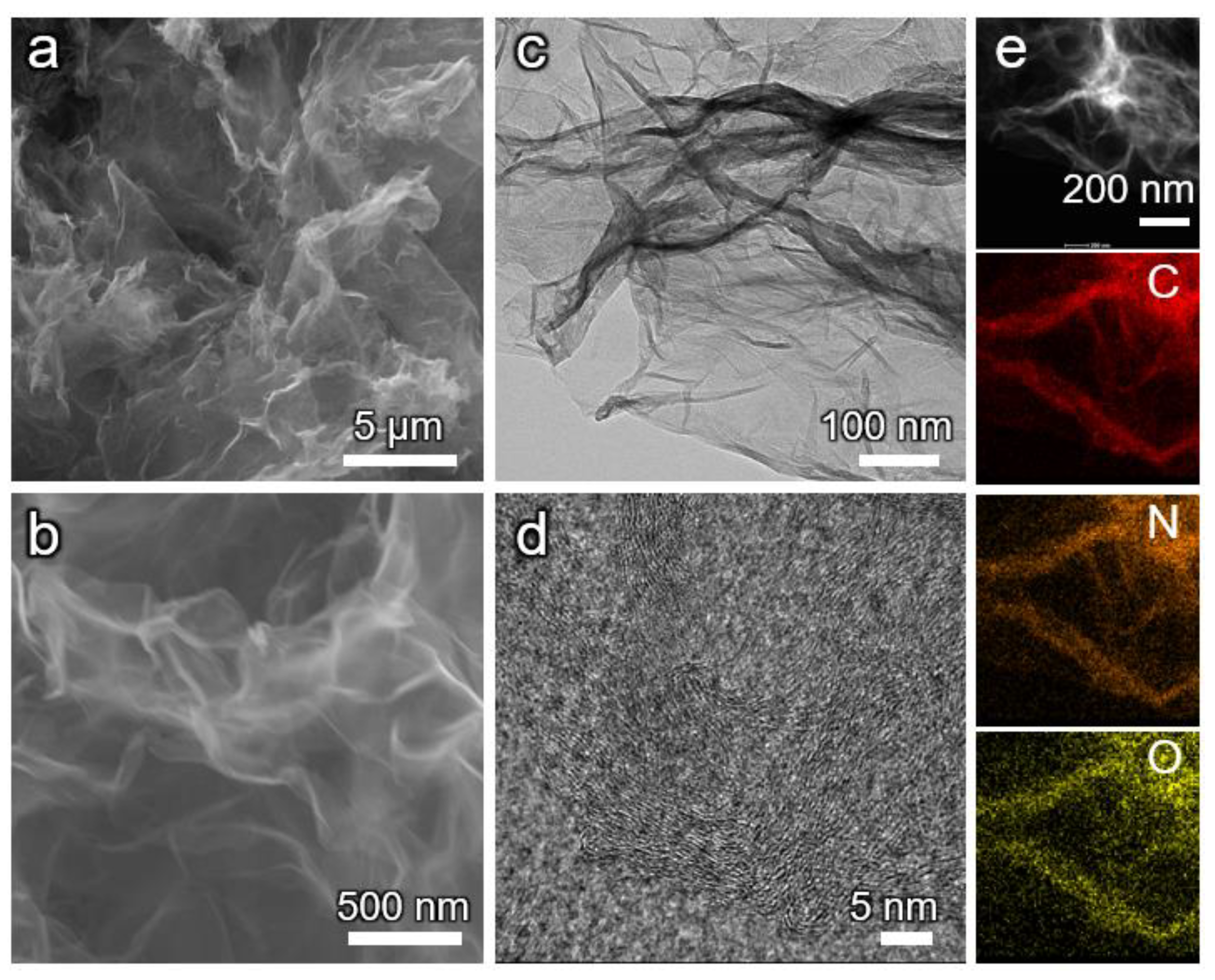
The morphological characterization of TpPa@rGO was analyzed using transmission electron microscopy (TEM) and scanning electron microscopy (SEM). The SEM images of TpPa@rGO reveal wrinkled nanosheets that form a porous structure (Figure 2a,b), showing a similar structure as compared to rGO (Figure S4). In contrast, SEM clearly depicts the fibrous structure of TpPa-COF (Figure S5). The TEM image indicates that no particles are observed on the surface of the nanosheets (Figure 2c). High-resolution TEM (HRTEM) revealed that the COF consisted of nanoscale crystalline regions (Figure 2d). The STEM image and elemental mapping demonstrate the uniform distribution of the C, N, and O elements (Figure 2e). These findings collectively affirm that the individual graphene sheets are fully covered with TpPa.
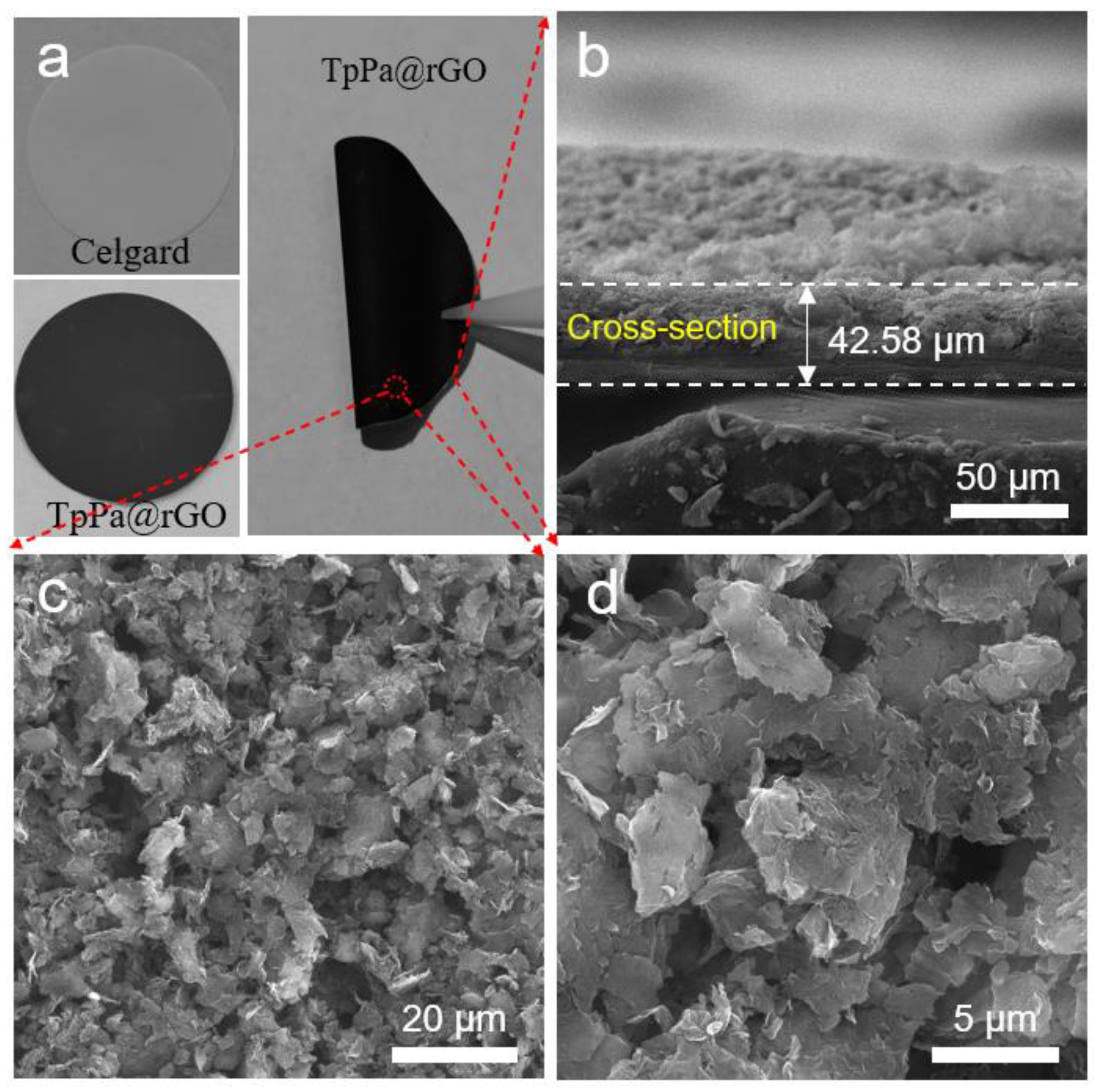
The modification process involved directly coating the Celgard polypropylene separator (Figure S6) with the slurry of TpPa@rGO. The SEM images show that TpPa@rGO uniformly covers the surface of the Celgard separator (Figure S7). In contrast, the TpPa@rGO modified separator displays a pore-free surface (Figure 3c,d), indicating that the original pores have been entirely covered by the TpPa@rGO. This suggests a robust physical barrier against polysulfides. The loading mass of the TpPa@rGO layer is 0.56 mg cm−2 with a thickness of ~18 μm (Figure S8). The TpPa@rGO/Celgard membrane exhibits an excellent mechanical stability without any observable cracks after bending (Figure 3a). The consistency of the TpPa@rGO/the Celgard thickness were measured using SEM images (Figure 3b) and according to thickness data from thickness measurements using thickness gauges. The contact angle test showed that the TpPa@rGO coating improved the hydrophilicity (Figure S9), which is due to the abundance of polar functional groups on TpPa@rGO. The contact angle of the TpPa@rGO/Celgard membrane (9.23°) is significantly lower compared to that of the pure Celgard separator (34.16°). It is indicated that the wettability is improved by the coating of TpPa@rGO. The TpPa@rGO/Celgard has an ionic conductivity of 1.4 mS cm−1, which is higher than the Celgard separator’s conductivity of 1.0 mS cm−1. It is indicated that after coating with TpPa@rGO, the separator is more conducive to the migration of Li+ (Figure S10).
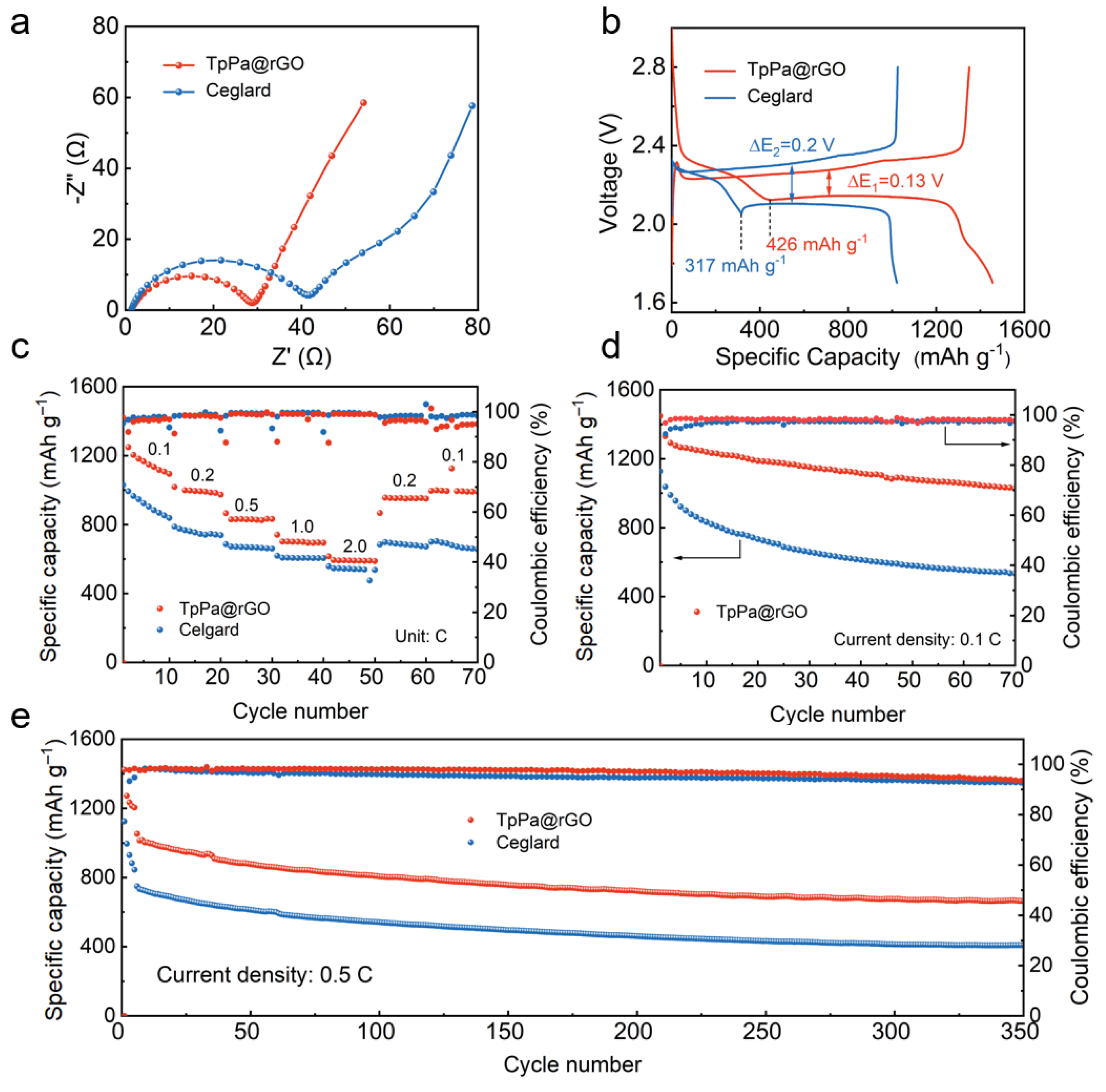
The performance of a TpPa@rGO/Celgard separator for Li–S batteries was evaluated using coin cells, pairing the Li anode and sulfur/carbon (S/C) cathode. SEM images show the surface of the sulfur/carbon (S/C) cathode (Figure S11). The performance was compared with that of a pristine Celgard separator. The EIS results for the Li–S cells with different separators before cycling measurement are compared in Figure 4a. The semicircle observed in the high-frequency area of the Nyquist plots represented the charge transfer resistance (Rct), while the straight line in the low-frequency region corresponded to a mass transfer process [31]. Notably, the Li–S cell using a TpPa@rGO/Celgard separator demonstrated a lower Rct value (28.9 Ω) compared to the Li–S cell using a Celgard separator (41.1 Ω). It is indicated that electron transfer is facilitated. The charge/discharge profiles at 0.1 C are shown in Figure 4b. The Li–S cells with a Celgard separator and a TpPa@rGO/Celgard separator show initial discharge capacities of 1021 and 1456 mAh g−1, respectively. The capacities of the upper plateau (CH) and lower plateau (CL) are compared. The upper plateau in the discharge curve corresponds to the reduction reaction of S8 into high-order polysulfides (Li2Sx, x = 4–8) [32]. Notably, the CH of the Li–S cell using a TpPa@rGO/Celgard separator (426 mAh g−1) is much higher than that of Li–S cells using a Celgard separator (317 mAh g−1), indicating a higher conversion rate from S8 into high-order polysulfides and higher utilization of the S cathode [33]. The CL corresponds to the reduction reaction of Li2S4 into solid Li2S2/Li2S [34,35,36]. The higher CL obtained for the cell using a TpPa@rGO/Celgard separator indicates the highest conversion rate from Li2S4 into solid Li2S2/Li2S. Furthermore, the Li–S cell using the TpPa@rGO separator shows the lowest polarization voltage (0.13 V) between the discharge and charge curves compared to the other cells, indicating the cell with a TpPa@rGO separator shows faster redox reaction kinetics and a better reversibility. The rate performances of the cells are compared in Figure 4c. The Li–S cell using a TpPa@rGO/Celgard separator provides capacities of 1018.9, 895.9, 740.6, and 615.8 mAh g−1 at rates of 0.2, 0.5, 1, and 2 C, respectively. This performance surpasses that of the Li–S cell using the Celgard separator, which experiences a rapid decline with an increasing current density (Figure S12). When the current density is restored from 2 to 0.2 C, the specific capacities of the Li–S cells using TpPa@rGO/Celgard and Celgard separators are 956 and 882 mAh g−1, respectively. After 150 cycles at 0.1 C (Figure 4d), the Li–S cell using the TpPa@rGO/Celgard separator maintains a specific capacity of 849.4 mAh g−1. In contrast, the capacity of the Li–S cell using a Celgard separator exhibits rapid fades from 1128 to 472.4 mAh g−1. The cycling performances of the cells at a current density of 0.5 C are further compared in Figure 4e. The capacity of the cell with the TpPa@rGO/Celgard separator remained at 663 mAh g−1 after cycling for 350 cycles, significantly surpassing that of the cell with the Celgard separator. At 1 C, the Li–S cell with a TpPa@rGO/Celgard separator delivers an initial specific capacity of 961.3 mAh g−1, and it retains 622.1 mAh g−1 after 300 cycles. In contrast, the capacity of the Li–S cell with the Celgard separator rapidly diminished to 340 mAh g−1 (Figure S13). In addition, compared with the pristine TpPa-COF interlayer [37] and the rGO interlayer (Figure S14), the heterostructured TpPa@rGO also demonstrated better performance. These findings underscore the positive effect of the heterostructured TpPa@rGO layer on improving the electrochemical performance of Li–S batteries, providing enhanced stability and capacity retention during cycling. This improved performance, on the one hand, is attributed to the inhibitory effect of the TpPa@rGO/Celgard separator on the shuttling of the polysulfides. Additionally, the TpPa@rGO acted as a secondary collector, improving the utilization of sulfur and significantly enhancing the capacity.

4. Conclusions

In conclusion, a 2D heterostructured TpPa@rGO composite is coated onto a commercial Celgard separator as a functional layer for Li–S batteries. The discharge capacity and cycling performance of Li–S batteries using a TpPa@rGO/Celgard separator are greatly enhanced compared to Li–S batteries using a conventional Celgard separator. In combination with structural characterization, their improved electrochemical performance can be attributed to the adsorption of polysulfide ions by TpPa@rGO, therefore inhibiting the shuttling effect for the polysulfides. Furthermore, heterostructures offer a complementary design approach for single materials with a strong electrical ability but weak adsorption performance or a good adsorption ability but weak electrical performance. rGO significantly improves the electronic conductivity of the separator layer, and the COF pore structure promotes Li+ transport. This work introduces a novel approach to designing high-energy-density and long-life Li–S batteries based on COF compartments.

Supplementary Materials

The following supporting information can be downloaded at https://www.mdpi.com/article/10.3390/en17071559/s1. Figure S1. (a) XRD pattern of TpPa-COF and (b) comparison of XRD patterns of TpPa-COF, rGO, and TpPa@rGO. Figure S2. (a) FT-IR spectra and (b) Raman spectra of rGO, TpPa-COF, and TpPa@rGO. Figure S3. XPS survey spectrum of TpPa@rGO composite. Figure S4. (a,b) SEM images of rGO. Figure S5. (a,b) SEM images of TpPa-COF. Figure S6. (a,b) SEM images of the Celgard separator. Figure S7. (a) SEM image and (b–d) elemental mapping of TpPa@rGO composite. Figure S8. Photograph of the thickness measurements of (a) Celgard separator and (b) TpPa@rGO-modified separator. Figure S9. The contact angles of the (a) Celgard separator and (b) TpPa@rGO/Celgard separator. Figure S10. The Nyquist plots of the symmetric cells with (a) Celgard separator, (b) rGO-modified separator, and (c) TpPar@rGO-modified separator and ionic conductivities of the (d) Celgard separator, (e) rGO-modified separator, and (f) TpPar@rGO-modified separator. Figure S11. (a,b) Surface SEM images and (c) cross-sectional SEM images of C/S cathode. Figure S12. The charge/discharge profiles of the Li–S cells with (a) Celgard separator and (b) TpPa@rGO-modified separator. Figure S13. The cycling performances of the Li–S cells with TpPa@rGO-modified separator and Celgard separator at 1 C. Figure S14. Cycling performances of the Li–S cell with rGO-modified separator at (a) 0.5 C and (b) 1 C. Table S1. The experimental elemental analysis (wt%) results for TpPa@rGO and the calculated element content (wt%) of TpPa.

Author Contributions

Conceptualization, B.D.; Methodology, Z.M.; Investigation, Z.M. and C.X.; Data curation, P.S.; Writing—original draft, Z.M. and M.L.; Supervision, B.D. All authors have read and agreed to the published version of the manuscript.

Funding

The work was funded by the Open Fund Project of the Low-Carbon Aerospace Power Engineering Research Center of the Ministry of Education (CEPE2020017), the Postgraduate Research & Practice Innovation Program of NUAA (xcxjh20220603), and the Priority Academic Development Program of Jiangsu Higher Education Institutions.

Data Availability Statement

The original contributions presented in the study are included in the article/supplementary material, further inquiries can be directed to the corresponding author.

Acknowledgments

We thank the Center for Microscopy and Analysis at NUAA.

Conflicts of Interest

The authors declare no conflict of interest.

References

  1. Seh, Z.W.; Sun, Y.; Zhang, Q.; Cui, Y. Designing high-energy lithium-sulfur batteries. Chem. Soc. Rev. 2016, 45, 5605–5634. [Google Scholar] [CrossRef] [PubMed]
  2. Wild, M.; O’Neill, L.; Zhang, T.; Purkayastha, R.; Minton, G.; Marinescu, M.; Offer, G.J. Lithium sulfur batteries, a mechanistic review. Energy Environ. Sci. 2015, 8, 3477–3494. [Google Scholar] [CrossRef]
  3. Yin, Y.-X.; Xin, S.; Guo, Y.-G.; Wan, L.-J. Lithium-sulfur batteries electrochemistry, materials, and prospects. Angew. Chem. Int. Ed. 2013, 52, 13186–13200. [Google Scholar] [CrossRef] [PubMed]
  4. Li, Y.; Guo, S. Material design and structure optimization for rechargeable lithium-sulfur batteries. Matter 2021, 4, 1142–1188. [Google Scholar] [CrossRef]
  5. Guo, R.; Yang, Y.; Huang, X.L.; Zhao, C.; Hu, B.; Huo, F.; Liu, H.K.; Sun, B.; Sun, Z.; Dou, S.X. Recent·advances·in multifunctional·binders·for high loading lithium-sulfur batteries. Adv. Funct. Mater. 2024, 34, 2307108. [Google Scholar] [CrossRef]
  6. Su, Y.-S.; Manthiram, A. Lithium-sulphur batteries with a microporous carbon paper as a bifunctional interlayer. Nat. Commun. 2012, 3, 1166. [Google Scholar] [CrossRef]
  7. Fan, L.; Li, M.; Li, X.; Xiao, W.; Chen, Z.; Lu, J. Interlayer material selection for lithium-sulfur batteries. Joule 2019, 3, 361–386. [Google Scholar] [CrossRef]
  8. Xia, P.; Li, S.; Yuan, L.; Jing, S.; Peng, X.; Lu, S.; Zhang, Y.; Fan, H.J. Encapsulating CoRu alloy nanocrystals intonitrogen-doped carbon nanotubes to synergistically modify lithium-sulfur batteries separator. Membr. Sci. 2024, 694, 122395. [Google Scholar] [CrossRef]
  9. Jeong, Y.C.; Kim, J.H.; Nam, S.; Park, C.R.; Yang, S.J. Rational design of nanostructured functionalInterlayer/separator for advanced Li-S batteries. Adv. Funct. Mater. 2018, 28, 1707411. [Google Scholar] [CrossRef]
  10. Huang, J.-Q.; Zhuang, T.-Z.; Zhang, Q.; Peng, H.-J.; Chen, C.-M.; Wei, F. Permselective graphene oxide membrane for highly stable and anti-sef-discharge lithium-sulfur batteries. ACS Nano 2015, 9, 3002–3011. [Google Scholar] [CrossRef]
  11. Huang, S.; Wang, Z.; Von Lim, Y.; Wang, Y.; Li, Y.; Zhang, D.; Yang, H.Y. Recent advances in heterostructure engineering for lithium sulfur batteries. Adv. Energy Mater. 2021, 11, 2003689. [Google Scholar] [CrossRef]
  12. Xiao, Z.; Yang, Z.; Wang, L.; Nie, H.; Zhong, M.E.; Lai, Q.; Xu, X.; Zhang, L.; Huang, S. A lightweight TiO2/graphene interlayer, applied as a highly effective polysulfide absorbent for fast, long-life lithium-sulfur batteries. Adv. Mater. 2015, 27, 2891–2898. [Google Scholar] [CrossRef]
  13. Kandambeth, S.; Dey, K.; Banerjee, R.J. Covalent organic frameworks: Chemistry beyond the structure. J. Am. Chem. Soc. 2019, 141, 1807–1822. [Google Scholar] [CrossRef]
  14. An, Q.; Wang, L.; Zhao, G.; Duan, L.; Sun, Y.; Liu, Q.; Mei, Z.; Yang, Y.; Zhang, C.; Guo, H. Constructing cooperative interface via Bi-functional COF for facilitating the sulfur conversion and Li+ dynamics. Adv. Mater. 2024, 36, 2305818. [Google Scholar] [CrossRef]
  15. Hu, B.; Xu, J.; Fan, Z.; Xu, C.; Han, S.; Zhang, J.; Ma, L.; Ding, B.; Zhuang, Z.; Kang, Q.; et al. Covalent Organic Framework Based Lithium-Sulfur Batteries: Materials, Interfaces, and solid-state electrolytes. Adv. Energy Mater. 2023, 13, 2203540. [Google Scholar] [CrossRef]
  16. Yoo, J.; Cho, S.-J.; Jung, G.Y.; Kim, S.H.; Choi, K.-H.; Kim, J.-H.; Lee, C.K.; Kwak, S.K.; Lee, S.-Y. COF-Net on CNT-Net as a molecularly designed, hierarchical porous chemical trap for polysulfides in lithium-sulfur batteries. Nano Lett. 2016, 16, 3292–3300. [Google Scholar] [CrossRef]
  17. Cao, Y.; Wu, H.; Li, G.; Liu, C.; Cao, L.; Zhang, Y.; Bao, W.; Wang, H.; Yao, Y.; Liu, S.; et al. Ion selective covalent organic framework enabling enhanced electrochemical performance of lithium-sulfur batteries. Nano Lett. 2021, 21, 2997–3006. [Google Scholar] [CrossRef]
  18. Wang, T.; He, J.; Zhu, Z.; Cheng, X.-B.; Zhu, J.; Lu, B.; Wu, Y. Heterostructures regulating lithium polysulfdes for advanced lithium-sulfur batteries. Adv. Mater. 2023, 35, 2303520. [Google Scholar] [CrossRef]
  19. Vincent, M.; Avvaru, V.S.; Rodríguez, M.C.; Haranczyk, M.; Etacheri, V. High-rate and ultralong-life Mg-Li hybridbatteries based on highly pseudocapacitive dual-phase TiO2 nanosheet cathodes. J. Power Sources 2021, 506, 230118. [Google Scholar] [CrossRef]
  20. Wu, S.; Jiang, Z.; Wu, C.; Li, H.; Huang, J.; Li, N.; Huang, S. High-content carbon layer confined small-molecule/covalent sulfur cathode enables long-life calcium-sulfur batteries in Hybrid-lon electrolyte. Adv. Funct. Mater. 2024, 2313441. [Google Scholar] [CrossRef]
  21. Pérez-Carvajal, J.; Boix, G.; Imaz, I.; Maspoch, D. The imine-Based COF TpPa-1 as an efficient cooling adsorbent that can be regenerated by heat or light. Adv. Energy Mater. 2019, 9, 1901535. [Google Scholar] [CrossRef]
  22. Ying, Y.; Tong, M.; Ning, S.; Ravi, S.K.; Peh, S.B.; Tan, S.C.; Pennycook, S.J.; Zhao, D. Ultrathin two-dimensional membranes assembled by ionic covalent organic nanosheets with reduced apertures for gas separation. J. Am. Chem. Soc. 2020, 142, 4472–4480. [Google Scholar] [CrossRef]
  23. Sun, J.; Klechikov, A.; Moise, C.; Prodana, M.; Enachescu, M.; Talyzin, A.V. A molecular pillar approach to grow vertical covalent organic framework nanosheets on graphene: Hybrid materials for energy storage. Angew. Chem. Int. Ed. 2018, 57, 1034–1038. [Google Scholar] [CrossRef]
  24. Li, Y.; Pei, B.; Chen, J.; Bing, S.; Hou, L.; Sun, Q.; Xu, G.; Yao, Z.; Zhang, L.J. Hollow nanosphere construction of covalent organic frameworks for catalysis:(Pd/C)@TpPa COFs in suzuki coupling reaction. Colloid. Interface Sci. 2021, 591, 273–280. [Google Scholar] [CrossRef]
  25. Karak, S.; Kumar, S.; Pachfule, P.; Banerjee, R. Porosity prediction through hydrogen bonding in covalent organic frameworks. J. Am. Chem. Soc. 2018, 140, 5138–5145. [Google Scholar] [CrossRef]
  26. Kandambeth, S.; Mallick, A.; Lukose, B.; Mane, M.V.; Heine, T.; Banerjee, R. Construction of crystalline 2D covalent organic frameworks with remarkable chemical (acid/base) stability via a combined reversible and irreversible route. J. Am. Chem. Soc. 2012, 134, 19524–19527. [Google Scholar] [CrossRef]
  27. Lei, R.; Zha, Z.; Hao, Z.; Wang, J.; Wang, Z.; Zhao, S. Ultrathin and high-performance covalent organic frameworks composite membranes generated by oligomer triggered interfacial polymerization. J. Membr. Sci. 2022, 650, 120431. [Google Scholar] [CrossRef]
  28. Zhang, H.; Li, X.; Xiao, C.; Xie, J.; Yan, X.; Wang, C.; Zhou, Y.; Qi, J.; Zhu, Z.; Sun, X.; et al. Enhanced selective electrosorption of Pb2+from complex water on covalent organic framework-reduced graphene oxide nanocomposite. Sep. Purif. Technol. 2022, 302, 122147. [Google Scholar] [CrossRef]
  29. Yao, Y.-H.; Li, J.; Zhang, H.; Tang, H.-L.; Fang, L.; Niu, G.-D.; Sun, X.-J.; Zhang, F.-M. Facile synthesis of a covalently connected rGO-COF hybrid material by in situ reaction for enhanced visible-light induced photocatalytic H2 evolution. J. Mater. Chem. A 2020, 8, 8949–8956. [Google Scholar] [CrossRef]
  30. Li, C.; Cao, S.; Lutzki, J.; Yang, J.; Konegger, T.; Kleitz, F.; Thomas, A. A covalent organic framework/graphene dual-region hydrogel for enhanced solar-driven water generation. J. Am. Chem. Soc. 2022, 144, 3083–3090. [Google Scholar] [CrossRef]
  31. Zhang, Y.; Guo, C.; Zhou, J.; Yao, X.; Li, J.; Zhuang, H.; Chen, Y.; Chen, Y.; Li, S.L.; Lan, Y.Q. Anisotropically hybridized porous crystalline Li-S battery separators. Small 2023, 19, 2206616. [Google Scholar] [CrossRef]
  32. Li, M.; Wang, Y.; Sun, S.; Yang, Y.; Gu, G.; Zhang, Z. Rational design of an allyl-rich triazine based covalent organic framework host usedas efficient cathode materials for Li-S batteries. Chem. Eng. J. 2022, 429, 132254. [Google Scholar] [CrossRef]
  33. Xu, J.; Bi, S.; Tang, W.; Kang, Q.; Niu, D.; Hu, S.; Zhao, S.; Wang, L.; Xin, Z.; Zhang, X. Duplex trapping and charge transfer with polysulfides by a diketopyrrolopyrrole-based organic framework for high-performance lithium-sulfur batteries. J. Mater. Chem. A 2019, 7, 18100–18108. [Google Scholar] [CrossRef]
  34. Shao, Q.; Wu, Z.-S.; Chen, J. Two-dimensional materials for advanced Li-S batteries. Energy Storage Mater. 2019, 22, 284–310. [Google Scholar] [CrossRef]
  35. Xing, C.; Chen, H.; Qian, S.; Wu, Z.; Nizami, A.; Li, X.; Zhang, S.; Lai, C. Regulating liquid and solid-state electrolytes for solid phase conversion in Li-S batteries. Chem 2022, 8, 1201–1230. [Google Scholar] [CrossRef]
  36. Shi, Z.; Tian, Z.; Guo, D.; Wang, Y.; Bayhan, Z.; Alzahrani, A.S.; Alshareef, H.N. Kinetically favorable Li-S battery electrolytes. ACS Energy Lett. 2023, 8, 3054–3080. [Google Scholar] [CrossRef]
  37. Xu, J.; An, S.; Song, X.; Cao, Y.; Wang, N.; Qiu, X.; Zhang, Y.; Chen, J.; Duan, X.; Huang, J.; et al. Towards high performance Li-S batteries via sulfonate-rich COF-modified separator. Adv. Mater. 2021, 33, 2105178. [Google Scholar] [CrossRef]
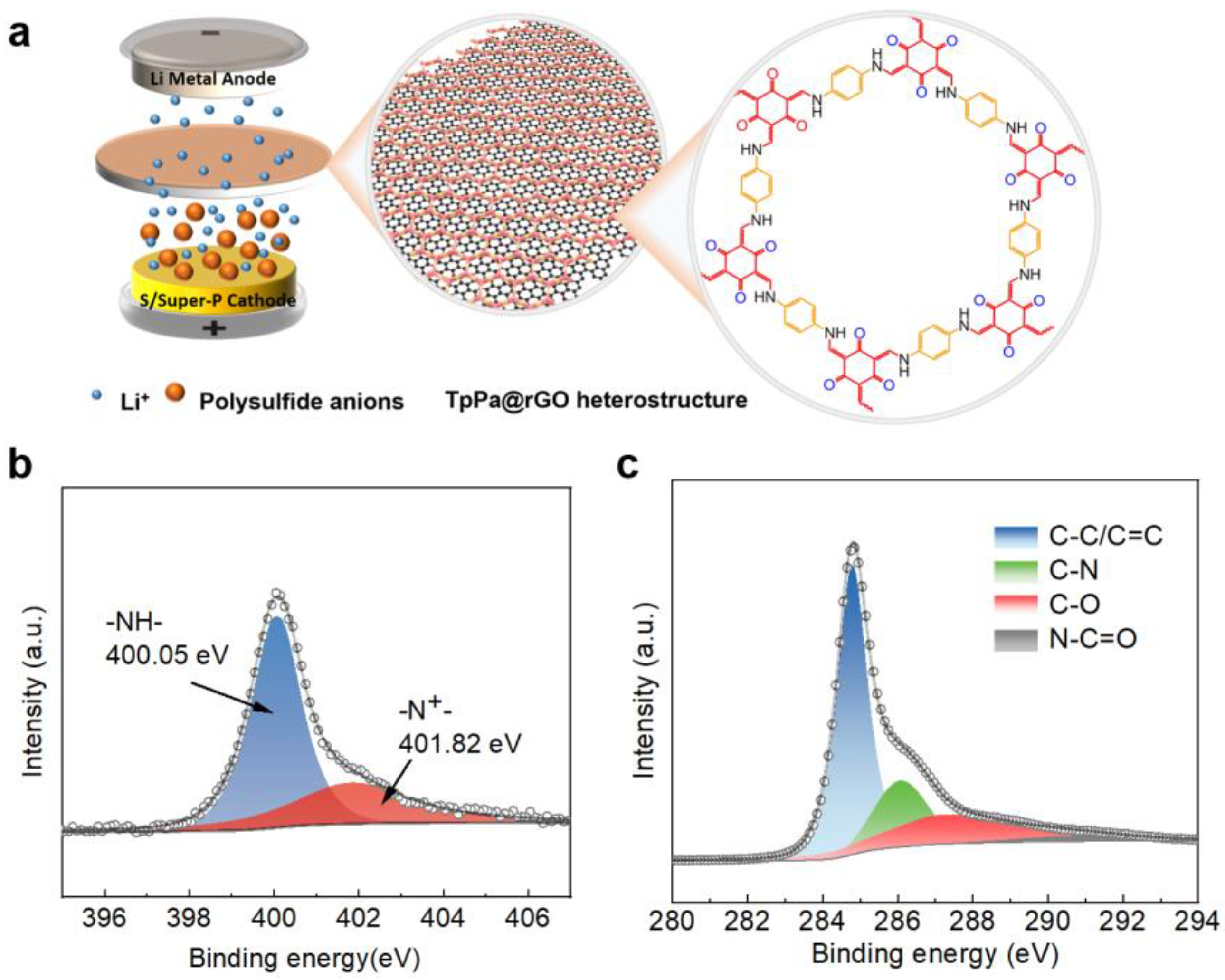
Figure 1. (a) The roles of TpPa@rGO heterostructure for Li–S batteries, (b) N 1s XPS spectra of TpPa@rGO, (c) C 1s XPS spectra of TpPa@rGO composite.
Energies 17 01559 g001
Figure 2. (a,b) SEM images, (c) TEM image, (d) HRTEM image, and (e) STEM image and corresponding EDS mapping of TpPa@rGO.
Energies 17 01559 g002
Figure 3. (a) Photograph of the Celgard and TpPa@rGO/Celgard separators, (b) cross-sectional SEM image, and (c,d) top-size SEM images of TpPa@rGO-modified separators.
Energies 17 01559 g003
Figure 4. Comparison of the electrochemical performances of Li–S cells using TpPa@rGO/Celgard and Celgard separators: (a) EIS spectra before cycling, (b) charge/discharge voltage profiles at a current of 0.1 C, (c) rate performances, long-term cycling performances at (d) 0.1 C and (e) 0.5 C.
Energies 17 01559 g004
Disclaimer/Publisher’s Note: The statements, opinions and data contained in all publications are solely those of the individual author(s) and contributor(s) and not of MDPI and/or the editor(s). MDPI and/or the editor(s) disclaim responsibility for any injury to people or property resulting from any ideas, methods, instructions or products referred to in the content.