Article

Power Flow Regulation Effect and Parameter Design Method of Phase-Shifting Transformer

1
Central China Branch, State Grid Corporation of China, Wuhan 430072, China
2
School of Electrical Engineering and Automation, Wuhan University, Wuhan 430072, China
*
Authors to whom correspondence should be addressed.
Energies 2024, 17(7), 1622; https://doi.org/10.3390/en17071622
Submission received: 1 March 2024 / Accepted: 20 March 2024 / Published: 28 March 2024

Abstract

:
In the context of carbon peaking and carbon neutrality goals, the integration of a large number of renewable energy sources may trigger significant tidal changes, leading to transmission congestion, wind and light abandonment, power oscillation, voltage and frequency fluctuations, etc. A phase-shifting transformer is a cost-effective and reliable power flow control equipment, but its key parameters lack systematic design methods. Based on the equivalent model of phase-shifting transformers, detailed design principles and methods have been proposed, and the configuration method of winding turns has been improved to facilitate calculation and control strategy formulation. The regulation effect of the phase-shifting transformer designed through simulation of power flow regulation in a typical 500 kV network is simulated. By adjusting the phase-shifting transformer, the power flow of heavy load lines can be transferred to light load lines, optimizing the power flow distribution and improving the transmission capacity of the cross-section.

1. Introduction

As the scale of the power grid and the scale of distributed energy resources continue to expand, China’s transmission network adopts high-voltage long-distance transmission and high transmission capacities due to the gradual movement of energy centers away from load centers. In addition, it also leads to uneven current distribution as well as serious impacts, such as line overloading and line circulation. Therefore, it is of great significance to improve the distribution of transmission line currents and enhance the power system regulation capability [1,2,3]. At present, our country, mostly through the adjustment of the transformer tap [4], changes the operation mode of generating units, casting compensation devices [5,6] and other control-of-power system operation modes [7,8] to solve the above problems [9,10]. None of these methods can flexibly regulate the tidal current.
Flexible AC transmission technology (FACTS) can flexibly regulate the power flow of transmission lines. FACTS power flow controllers are mainly divided into power electronic and electromagnetic types [11,12]. Power electronic power flow controllers based on power electronic devices are typically represented by the Unified Power Flow Controller (UPFC), which has comprehensive functions but high equipment manufacturing and maintenance costs [13,14,15,16]. The electromagnetic power flow controller, based on multi winding transformers, is typically represented by the Phase-Shifting Transformer (PST) [17] and the Sen Transformer (ST) [18,19] proposed on the basis of the UPFC. The latter has a simple structure, high reliability, and good economy.
References [20,21,22] provide a review of the engineering applications of PSTs. PSTs can be either mechanical and thyristor-based depending on load voltage regulation, with mechanical being the main method in engineering applications, while research on thyristor-based methods is mostly focused on theoretical and simulation aspects. References [23,24,25] elaborate on the current research status of PSTs and analyze the advantages, disadvantages, and application scenarios of different types of PST, finding that a thyristor-type PST has faster response speed and performs well in situations with fast dynamic responses and small capacities, but the cost of the former is much lower than that of the latter. Due to the limitations of the mechanical switch itself, the former can only be used in situations with low response speed requirements and high capacity. Reference [26] has improved the structure of traditional mechanical PSTs and proposed a new electromagnetic unified power flow controller (EUPFC), which has a larger adjustment range and faster response speed than traditional PSTs. Considering the insulation cost, a EUPFC is often used in situations with voltage levels below 220 kV. Reference [27] analyzed the feasibility of using dual core symmetrical PSTs to improve steady-state power flows in actual power grids and conducted simulation research on the control characteristics of the PST switching operation.
A PST changes the voltage phase difference of the line by injecting a compensating voltage, thereby regulating the power flow of the line, achieving the goal of optimizing power flow distribution, improving line utilization, and increasing the section transmission capacity. Therefore, the phase-shifting range, winding turns, and other parameters of a PST are quite important for its performance. References [28,29] consider PSTs as ideal devices and use optimization algorithms to determine the construction site of a PST. However, this is only a system level optimization and does not consider the influence of the parameters of PSTs themselves. Reference [30] proposed an equation to constrain the number of winding turns and conducted simulation calculations based on the saturation effect of the DC component on the core of a PST. However, since the saturation degree of the core does not involve the working principle of the PST, the constraints proposed will not optimize the performance of the PST and can only serve as necessary conditions to assist in design. Reference [31] constrains winding parameters based on operating costs and economic considerations; however, due to the lack of consideration for the working characteristics of a PST, economic constraints alone cannot directly guide actual parameter design. It can be seen that many articles have considered parameter optimization related to PSTs, but only in terms of the system level optimization, without involving the equipment itself. Additionally, from the perspective of iron core saturation, operating costs, and other factors unrelated to the principle of PSTs, the obtained conditional constraints have little guiding significance. Therefore, based on the equivalent model of a PST, the design principles and methods for their key technical parameters are proposed and the number of turns of the regulating winding are optimized to ensure that the phase shift angle corresponding to each tap is the same, which is convenient for equipment design and control strategy formulation. We conducted simulation of power flow regulation in a typical 500 kV network scenario, adding a controllable phase shifter to reduce the load rate of heavy-duty lines, greatly reducing the imbalance of the line power flow.

2. Power Flow Regulation Mechanism of PSTs

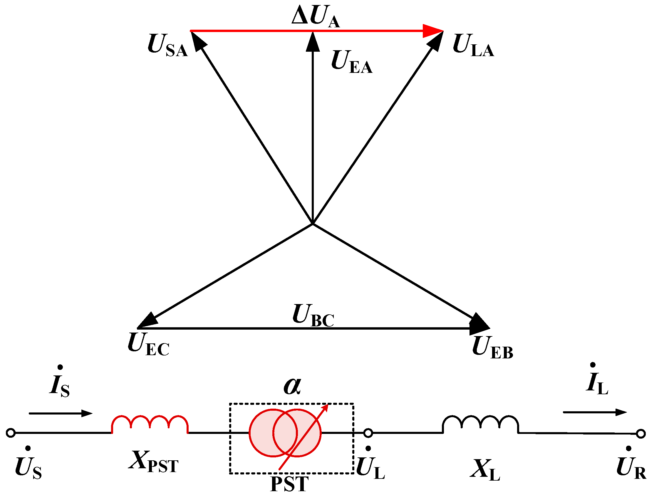
2.1. The Influence of Phase-Shifting Transformer on Line Power Flow

In transmission lines, there is a voltage drop and phase angle difference between the power supply side and the load side. When no control or regulation devices are put into operation, the power flow of parallel transmission lines and the ring network is distributed according to impedance. A PST is installed at the head end of a high-voltage transmission line, which can be equivalent to the reactance and ideal transformer model connected in series in the line, as shown in Figure 1.
In Figure 1, US and UR represent the voltage amplitude at the beginning and end of the line, respectively. UL is the voltage amplitude after PST adjustment. UE is the excitation voltage obtained by the excitation transformer from the line, ΔU represents the compensation voltage of the series transformer connected in series in the line. IS and IL, respectively, represent the system current before and after the adjustment of the PST. Additionally, α represents the phase shift angle generated by the PST. XL. XPST represents the equivalent impedance of the line and PST, respectively.
In high-voltage power grids, due to the fact that the equivalent reactance of transmission lines is much greater than their equivalent resistance value, line losses are ignored. After adding the compensation voltage ΔUPST of the PST injection line to the system sending terminal voltage US, the phase angle change is α, while δ is the initial phase difference between the two sides of the system before adjustment. After the PST is put into the transmission line, the active and reactive power injected into the first end of the line are [32,33]:
P = U s 2 R L   +   U s U L X L s i n δ     U s U L R L c o s δ R L 2   +   X L 2 Q = U s 2 X L     U s U L R L s i n δ     U s U L X L c o s δ R L 2   +   X L 2
After the PST is connected, the active power transmitted by the line is still a sine function, but its phase is added with ±α Angle change, thus regulating the active power flow of the line.

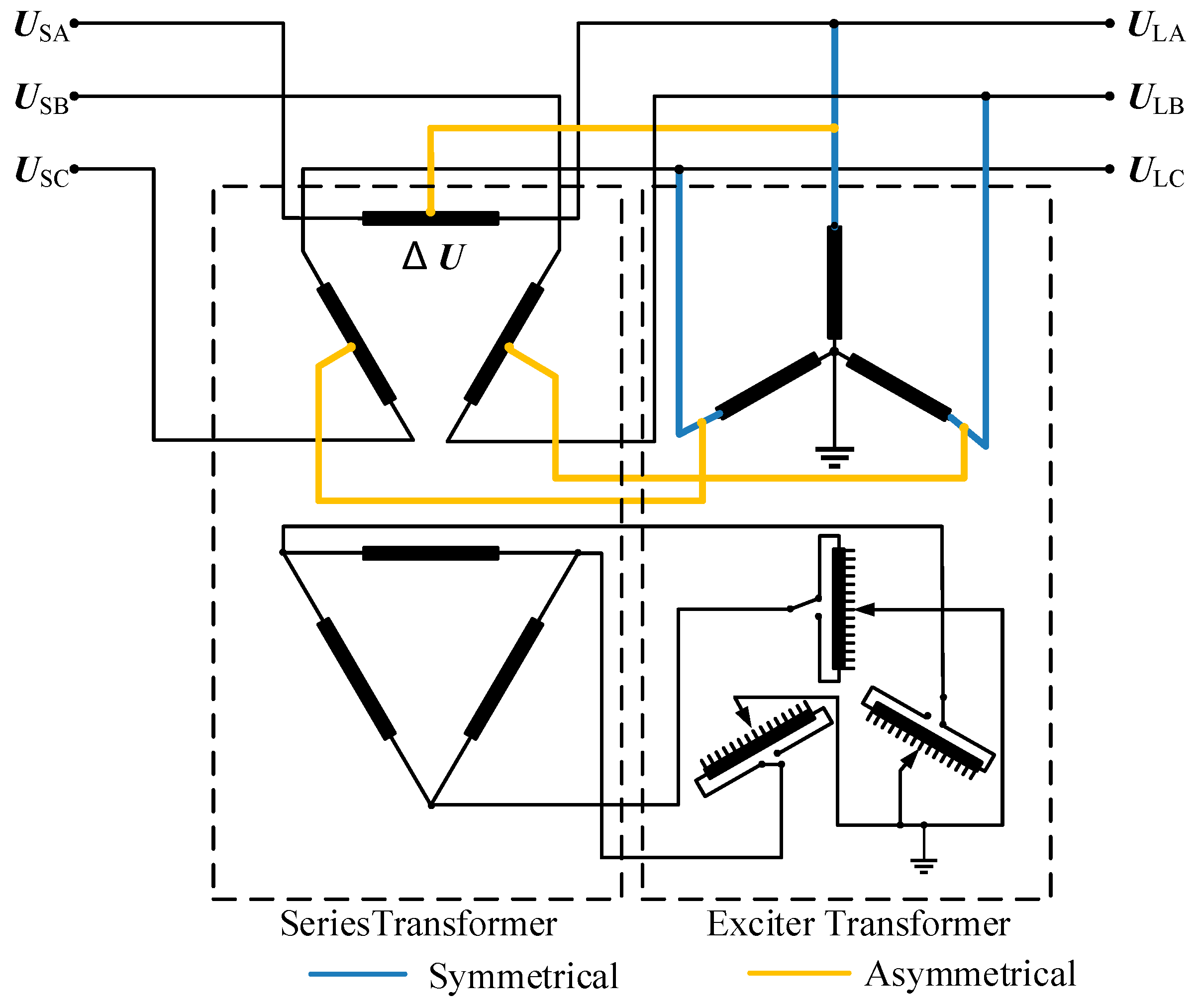
2.2. Classification of Phase-Shifting Transformers

A PST can be divided into symmetric and asymmetric types based on its electrical characteristics. According to the structure of the transformer body, it can be divided into both single-core-type and dual-core-type. The topology of the dual core PST is shown in Figure 2. The dual-core phase-shifting transformer includes two independent transformers in a magnetic circuit structure, namely series transformer and excitation transformer. Its connection method is shown in Figure 2. When the rated capacity and voltage level are low, the two transformer bodies can be placed in the same box.
An asymmetric PST simultaneously changes the amplitude and phase angle of the line voltage. The symmetrical PST ensures that the voltage amplitude remains unchanged before and after compensation, only changing its phase angle. At present, the most commonly used PST in engineering is the bicentric symmetric type [22].

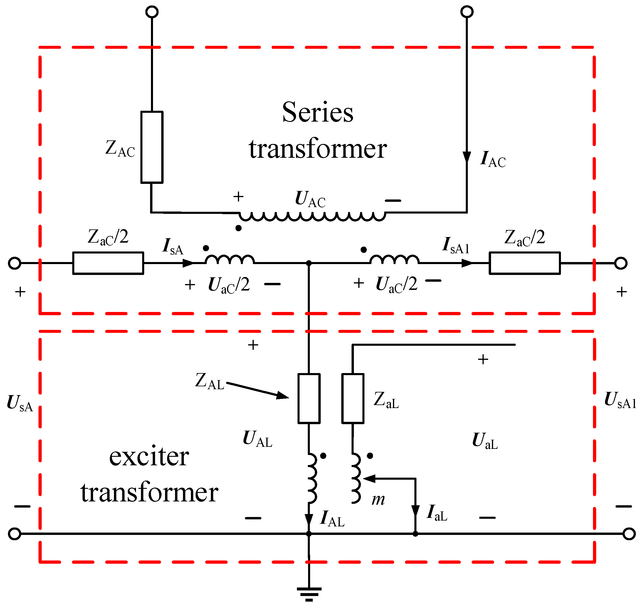
2.3. Load Circuit Model of Phase-Shifting Transformer

Taking the A-phase lag regulation as an example, this chapter, based on the PST topology shown in Figure 2 and the T-shaped equivalent circuit diagram of the two winding transformer and the three winding transformer, and based on the characteristic that the excitation impedance of the transformer is far greater than the winding leakage impedance, makes infinite treatment on the excitation impedance of the two winding transformer and the three winding transformer, combining the working principle of PSTs to obtain the single-phase equivalent circuit diagram of the PST in the positive sequence (taking the lag regulation as an example), as shown in Figure 3. In Figure 3, ZAC and ZaC are the leakage impedances of the primary winding AC and the secondary winding aC of the series transformer, respectively. ZAL and ZaL are the leakage impedances of the primary winding AL and the secondary winding aL of the excitation transformer, respectively. UsA and IsA are the voltage and current phasors of the first end (power supply side) before compensation. UsA1 and IsA1 are the voltage and current phasors of the first end (load side) after compensation. IAC is the current in the primary winding AC of the series transformer, while UAL and IAL represents the voltage phasor and current phasor of the primary winding AL of the excitation transformer. Additionally, UaL and IaL represent the voltage phasor and current phasor of the secondary winding aL of the excitation transformer, while UAC and UaC represent the voltage phasor of the primary winding AC and secondary winding aC of the series transformer, as well as the voltage between the power side and the load side.
Let NC and NL be the ratio of the series transformer and the excitation transformer, D = m/mmax be the ratio of the number of turns of the secondary winding of the excitation transformer to the maximum number of turns of the winding, and let the adjustment level of the on-load tap changer be m.
From Figure 3, it can be seen that the pre compensation first terminal voltage phasor UsA and the post compensation first terminal voltage phasor UsA1 are, respectively:
U sA = U AL + U AC 2 N C + I sA Z aC 2
U sA 1 = U AL U AC 2 N C I sA 1 Z aC 2
Under load conditions, the output phase shift angle of a PST α by its no-load phase shift angle α and internal shift phase angle β, β is caused by the voltage drop on the impedance of the PST. The joint decision not only affects the structure and winding size of the transformer, but also affects the selection of the tap changer.
When the regulating tap of the voltage regulating winding (secondary side) of the excitation transformer is different, its equivalent impedance will also change. When the maximum adjustable tap is nmax and the selected tap is n, the current position of the tap of the excitation transformer regulating winding is represented by D:
Considering that a PST only has a positive sequence component during normal operation, under positive sequence conditions, the AC voltage UAC and current IAC of the primary winding of the series transformer can be obtained as:
U AC = j 3 U aL + I AC Z AC
I AC = 1 2 N C I SA + I SA 1
According to the PST ratio relationship, the primary side voltage UAL of the excitation transformer can be determined as:
U AL = U aL I aL Z aL D N L D + I AL Z AL
The relationship between the primary side current IAL and the secondary side current IaL of the excitation transformer satisfies the following equation:
I AL I aL = D N L
Under positive sequence conditions, the electrical connection between the primary winding of the series transformer and the secondary winding of the excitation transformer can be obtained:
I aL = j 3 I AC
I AL = I sA I sA 1
Therefore, eight equations containing 10 variables have been established, and the relationship between the phase quantities UsA, IsA, UsA1, and IsA1 on the power and load sides can be obtained by transforming Equations (2)–(9). The specific derivation is as follows:
Subtracting Equation (2) from Equation (3) yields the power side voltage UsA:
U sA = U sA 1 + U AC / N C + I sA Z aC 2 + I sA 1 Z aC 2
The secondary winding aL voltage UaL of the excitation transformer can be obtained by organizing Equations (4), (5), and (10):
U aL = U sA 1 N C j 3 + I sA + I sA 1 N C j 3 Z AC 2 N C 2 + Z aC 2 U sA N C j 3
The load side voltage UsA1 can be obtained by adding Equations (2) and (3):
U sA 1 = 2 U AL U sA + Z aC 2 ( I sA I sA 1 )
According to Equations (5) and (7)–(9), it can be concluded that:
I sA 1 = I sA 2 N L N C j 3 D 2 N L N C + j 3 D
I aL = I sA j 2 3 N L 2 N L N C + j 3 D
I AL = I sA j 2 3 D 2 N L N C + j 3 D
By combining Equations (11)–(15), the load side voltage UsA1 can be obtained:
U sA 1 = U sA 2 N L N C     j 3 D j 3 D   +   2 N L N C I sA 2 N L N C     j 3 D j 3 D   +   2 N L N C 12 D 2 Z AL   +   4 N L 2 Z AC   +   N C 2 Z aC 4 N L 2 N C 2   +   3 D 2 + 12 N L 2 Z aL D   +   3 D 2 Z aC 4 N L 2 N C 2   +   3 D 2
In the above equation:
2 N L N C j 3 D j 3 D + 2 N L N C = 1
Assuming that the phase shift angle varies with the adjustment level is αm. Then, it can be concluded that:
e j α m = 2 N L N C j 3 D j 3 D + 2 N L N C
By combining Equation (13), the amplitudes of the power side current IsA, and the load side current IsA1 can be obtained:
I sA 1 = I sA
According to Equation (16), it can be assumed that:
U sA 1 = U sA e j α m I sA e j α m Z eqm
In the above equation, Zeqm is the equivalent impedance of the phase-shifting transformer:
Z eqm = 12 D 2 Z AL + 4 N L 2 Z AC + N C 2 Z aC + 12 N L 2 Z aL D + 3 D 2 Z aC 4 N L 2 N C 2 + 3 D 2
When a PST makes advance regulations, the equivalent impedance Zeqm is the same as that of lag regulation.
By further organizing Equation (21) with D = 1, it can be concluded that:
Z eqm X eqm = Z aC + 12 4 N L 2 N C 2 + 3 Z AL + N L 2 Z aL + 1 3 N L 2 Z AC
When m equals 0, the transformation ratio NL is taken as infinity, and taking the limit of Equation (22) yields:
Z eqm = Z aC + Z AC / N C 2
According to Equation (20), it can be seen that the real PST can be represented by an ideal PST connected in series with an internal impedance Zeqm that varies with the phase angle; therefore, the equivalent circuit diagram of the dual terminal power supply system with a PST is shown in Figure 4.
The phasor relationship of voltage and current at each node in Figure 4 is shown in Figure 5.
In Figure 5, IL represents the current at the load side after compensation, while UsA0, UsA1, and UrA represent the load side voltage phasor under no-load conditions, the voltage phasor on the power side, and the load side voltage phasor, respectively. Additionally, φL is the load power factor angle, α0 is the phase shift angle when unloaded, β is the internal phase angle formed by the line circuit flowing through the equivalent impedance of the PST, with positive values indicating lead and negative values indicating lag. As shown in Figure 5, the phase shift angle under load αL is determined by what the no-load phase shift angle of the PST α0 and internal shift phase angle β jointly decides.
The internal phase angle β is related to the internal impedance, load current and corresponding power factor, and its calculation expression is as follows:
β = arctan I L X eqm c o s φ R eqm s i n φ U L + I L X eqm s i n φ + R eqm c o s φ

3. Design of Key Parameters for Phase-Shifting Transformers

3.1. Phase Shift Angle of a Phase-Shifting Transformer

After analyzing the system, the rated phase shift range to obtain the required power adjustment and the natural phase difference of the line must be designed. The phase difference between the two ends of the line when the PST is not installed is defined as the natural phase difference, denoted as δ, the transmission power is denoted as P0, the target transmission power is denoted as Pr, and the difference between the two transmission powers is the power that needs to be adjusted ΔP = PrP0. When the voltage amplitude at both ends of the line remains unchanged, the adjustment to the maximum phase shift angle required for the target power αr is:
α r = arcsin P r X L U s U R δ
Specifically, when faults N-1 and N-2 occur, the overloaded line may experience severe overload, resulting in severe heating of the line. When the temperature exceeds the thermal stability limit, the line will melt, causing serious power outages. Therefore, in extreme cases of N-1 and N-2 faults, the maximum overload power Pol (over load) should be limited below Pmax through phase-shift control. When considering the above situation, the maximum phase shift angle is taken as:
α o l = arcsin P o l X L U S U R arcsin P m a x X L U S U R
The maximum phase shift angle required for PST αmax is:
α m a x = m a x a r , a o l
Under load conditions, the leading phase shift angle is due to β. The impact cannot reach the rated no-load phase shift angle, and the hysteresis phase shift angle may exceed the rated value. Therefore, it is necessary to leave a certain margin when designing the rated phase shift range. Considering the phase shift angle deviation under load conditions, the rated phase shift range of PST αmax should be:
α m a x = m a x α + β , α s l + β

3.2. Main Electrical Parameters of Phase-Shifting Transformer

The primary side of the excitation transformer of the PST is directly connected to the head or end of the line, and the rated voltage level of the line is marked as UN. Therefore, the rated voltage UE1N on the primary side should be equal to the highest operating voltage of the line:
U E l N = 1.1 U N
Due to the fact that the primary side of the PST series transformer is directly connected in series in the line, in addition to all the current flowing through the line, the rated current IB2N on the secondary side should be taken as the maximum allowable current Imax of the line:
I B 2 N = I m a x
Assuming a rated phase shift angle range of ±α, the maximum voltage on the voltage regulating winding is the maximum compensation voltage that can be injected into the line. Therefore, the expression for adjusting the rated voltage UB1N of the primary winding of a series transformer is:
U B 1 N = U N s i n α 2
The rated nominal power capacity SN is equal to the sum of the capacities of three series windings:
S N = 6 U B 1 N I B 1 N 3 = 3 U N I m a x s i n α 2
The rated current IE1N on the primary side of the excitation transformer is:
I ¯ E 1 N = S N 3 U E 1 N 0.91 I m a x s i n α 2

3.3. Configuration of Winding Turns for Phase-Shifting Transformers

The number of turns set for each stage of the voltage regulating winding of a conventional transformer is the same, and the voltage between each tap is the same, as shown in Figure 6a.
This article optimizes the configuration of the PST-voltage-regulating winding turns to ensure that the phase shift angle of each tap is the same, which is helpful for parameter calculation and control strategy design, as shown in Figure 6b. Among them, USV represents the voltage between each tap of traditional PST. θ Indicates the phase shift angle of each stage change in the voltage regulating winding, while USVk represents the inter tap voltage of the PST with an optimized winding turns configuration and k is the tap number.
Let the change in phase shift angle between different taps in a traditional PST be θk (k is the tap number). As the voltage USV changed for each tap is the same, there are:
θ k = arcsin k U S V U S A arcsin k 1 U S V U S A
The change in phase shift angle between different taps of a PST after optimizing the number of winding turns is the same, all of which are θ. The corresponding level voltage USVk for each tap is:
U S V k = U S A s i n k θ U S A s i n k 1 θ = 2 U S A cos 2 k 1 θ 2 sin θ 2
The number of coil turns in a transformer winding is mainly related to its rated voltage, transmitted active power, and the cross-sectional area of the iron core. In a power transformer with an AC frequency of 50 Hz, there is the following expression:
A T = 1.25 P T D T = 1.13 I T δ T
Among them, AT is the cross-sectional area of the core. PT is the active power of the PST, while DT is the wire diameter. IT is the winding current, δT is the current density, and the relationship between AT and PT, as well as the relationship between DT, IT, and δT, are based on empirical formulas [34].
NT is the number of winding turns, BT is the magnetic permeability of silicon steel sheets, et is the rated voltage on the winding, and it can be inferred from the voltage characteristics of the transformer that:
e t = 4.44 f N T B T A T = N T B T A T 45 × 10 4
and the permeability of small and medium-sized PSTs is selected between 6000 H/m and 12,000 H/m. Currently, the permeability of silicon steel sheets is generally around 10,000 H/m; therefore, it can be concluded that:
N T = 45 e t B T × A T × 10 4 = 45 e t A T × 10 8

4. Simulation of 500 kv Tie Line Power Flow Regulation

4.1. Typical Scenario Trend Regulation Requirements

The overall external power receiving capacity of a 500 kV ultra-high voltage power grid is mainly limited by the bipolar blocking fault of a certain DC line. For the convenience of simulation analysis, the entire AC system is equivalently modeled as a dual power system with multiple parallel lines, as shown in Figure 7.
Power 1 and Power 2 are connected through five 500 kV parallel lines. In the case of natural distribution of power flow, the distribution of power flow is uneven. If the DC line in the system experiences bipolar blocking, the transferred power flow will put L4 and L5 lines at risk of overload. The specific parameters are shown in Table 1.
In general, after the DC line is bipolar locked, L4 and L5 will first reach the rated transmission capacity, while the other three lines have a certain margin. Therefore, the overload problem of lines L4 and L5 after DC bipolar locking is a key factor restricting the external power receiving capacity of the power grid in this area.
The purpose of installing a controllable phase-shifting transformer in this ultra-high voltage power grid is to achieve the desired maximum AC/DC power receiving capacity in the region through the power adjustment strategy (adjusting phase shift angle) of the phase-shifting transformer under different initial operating modes (power flow distribution). According to the power flow transfer ratio calculation under fault conditions, the maximum transmission power P1max and P2max are both about 1050 MW. P3max is about 1200 MW, and P4max and P5max are both about 1100 MW.

4.2. Parameter Design and Performance Verification of Phase-Shifting Transformers

The actual power flow of the transmission line was simulated using MATLAB software R2022a, and the power flow regulation effect of the PST on a typical 500 kV power grid was analyzed. Based on the parameter design method of the PST mentioned earlier, as well as the current power flow situation of the actual network, the specific parameters of a 500 kV PST are designed as shown in Table 2.
According to the calculation of the PST equivalent model proposed in this article, the equivalent impedance of PST varies within the range of 11–15.5% with the tap of the voltage regulating winding. The transformation ratio of the series and excitation transformers of PSTs is calculated according to the formula derived in this article, and corresponding parameter settings are made in the simulation model.
A simulation analysis in Simulink software to test the phase shift angle corresponding to each tap of PST under no-load and rated load conditions was conducted, as shown in Table 3 and Figure 8. It can be seen that, in the case of advancing regulation, due to the influence of internal impedance, the phase shift angle under the load of each tap is less than the no-load phase shift angle. If the internal impedance of the PST is not calculated, the maximum phase shift error of 2.67° will be brought, which will bring about very large power errors when power flow regulation is carried out in actual projects. When the tap position is 10, the maximum no-load phase shift angle is 22.67° and the phase shift angle under load is 20.09°. The maximum phase shift error for 10 taps is only 0.26°. The calculation method proposed in this article greatly reduces the phase shift angle error of each tap.
Accordingly, the PST simulation model lagging adjustment phase shift angle is tested, the tap is switched to negative by using the polarity switch, and the no-load and load phase shift angles of each tap are simulated and tested, with the results being shown in Figure 9. From the results, it can be seen that, when the tap is −10, the maximum lagging no-load phase shift angle is −22.70°, and the phase shift angle under load is −20.09°. If the internal impedance of the PST is not calculated, the maximum phase shift error is −2.70°. After designing the transformation ratio according to the design method in this article, the maximum phase shift error is reduced to −0.39°.
From the above simulation results, it can be seen that the parameter calculation method proposed in this article is of great significance for the design and application of PSTs. After correcting the transformation ratio of each tap, the phase shift angle corresponding to each tap of the PST is uniform, which is more convenient for setting control strategies and reducing power flow adjustment errors.

4.3. Simulation of Power Flow Optimization for Phase-Shifting Transformers

As analyzed earlier, in order to prevent overloading of L4 and L5 in the event of bipolar blocking faults in DC lines, it is necessary to reduce the proportion of L4 and L5 power in this area. The PSTs can be installed in L1, L2 and L3 lines, respectively, for advancing adjustment. It is also possible to install the PSTs in L4 and L5, respectively, for lagging adjustment, so as to transfer part of the power to L1, L2 and L3.
Taking advancing regulation simulation as an example, some results are shown in Figure 10. After installing a PST on L1, L2, and L3, the active power changes of the five lines are shown in Figure 9 and Figure 10. Starting from t = 5 s, the tap changer gradually switches from Level 0 to Level 10.
As the phase shift angle of the PST output increases, a portion of the power of lines L4 and L5 has been transferred to L1, L2, and L3 so that L4 and L5 will not overload when a bipolar blocking fault occurs in the DC line. However, continuing to increase the tap position will further reduce the power of L4 and L5, which will cause the load rate of L1 and L2 to be too high. When N-1 faults occur in the line, these two lines will face the risk of overload.
At the moment of tap changing, the voltage on the primary winding of the series transformer will suddenly change, introducing a large number of harmonics. The maximum THD within one cycle reaches about 50%. Due to the damping effect of the transition resistance, the transient process ends and the harmonics are basically eliminated after several cycles. The transient time from 0 to 1 is the longest, lasting about 0.8 s, i.e., after 40 cycles, the THD of the voltage drops below 5%, as shown in Figure 11 and Figure 12.
In practical applications, if a PST uses different types of on-load voltage regulating switches, the transient process during tap changing will also be different. The transient process of power electronic switches is smaller. Correspondingly, its cost is also higher.
From the above analysis results, it can be seen that there are two options for using a PST to regulate the flow division of the ultra-high voltage power grid in this area. According to the simulation results, the adjustment results of the two options are shown in Table 4.
Scheme I: Three double-core symmetrical phase-shifting transformers are installed in lines L1, L2 and L3. The phase shifter makes advance adjustment to the line phase angle. The phase-shifting angle required by L1 and L2 is 6°, and the phase-shifting angle required by L3 is 15°.
Scheme II: Two double core symmetrical phase-shifting transformers are installed in the L4 and L5 lines, and the phase-shifting angle required by L4 and L5 is −10°.
Through the adjustment of the PST, partial power of lines L4 and L5 can be transferred to lines L1, L2, and L3. In this way, when the DC lines in this area of the power grid experience bipolar blocking faults or AC line N-1 faults, all lines almost simultaneously reach full load. For heavy-duty lines, a PST avoids the risk of overload and improves the stability of the system. For light load lines, enabling them to transmit more active power flow can effectively solve energy transmission problems and improve energy utilization efficiency.

5. Conclusions and Prospectives

The article provides a specific derivation and analysis of the power flow regulation principle and parameter design method for controllable phase-shifting transformers. A load model for PSTs is established and, based on this, a calculation method for their key parameters is proposed. The configuration of winding turns is optimized and the correctness of the theory is verified through simulation, helping us draw the following conclusions:
(1)
A PST injects a compensating voltage to change the voltage phase difference of the line, thereby regulating the power flow of the line. The double core symmetrical controllable phase-shifting transformer is most suitable for networks above 500 kV. Considering the influence of its internal impedance, it may cause a certain deviation in the output phase-shifting angle. Therefore, it is important to leave a certain margin in the design or eliminate this influence through the design of the transformer ratio.
(2)
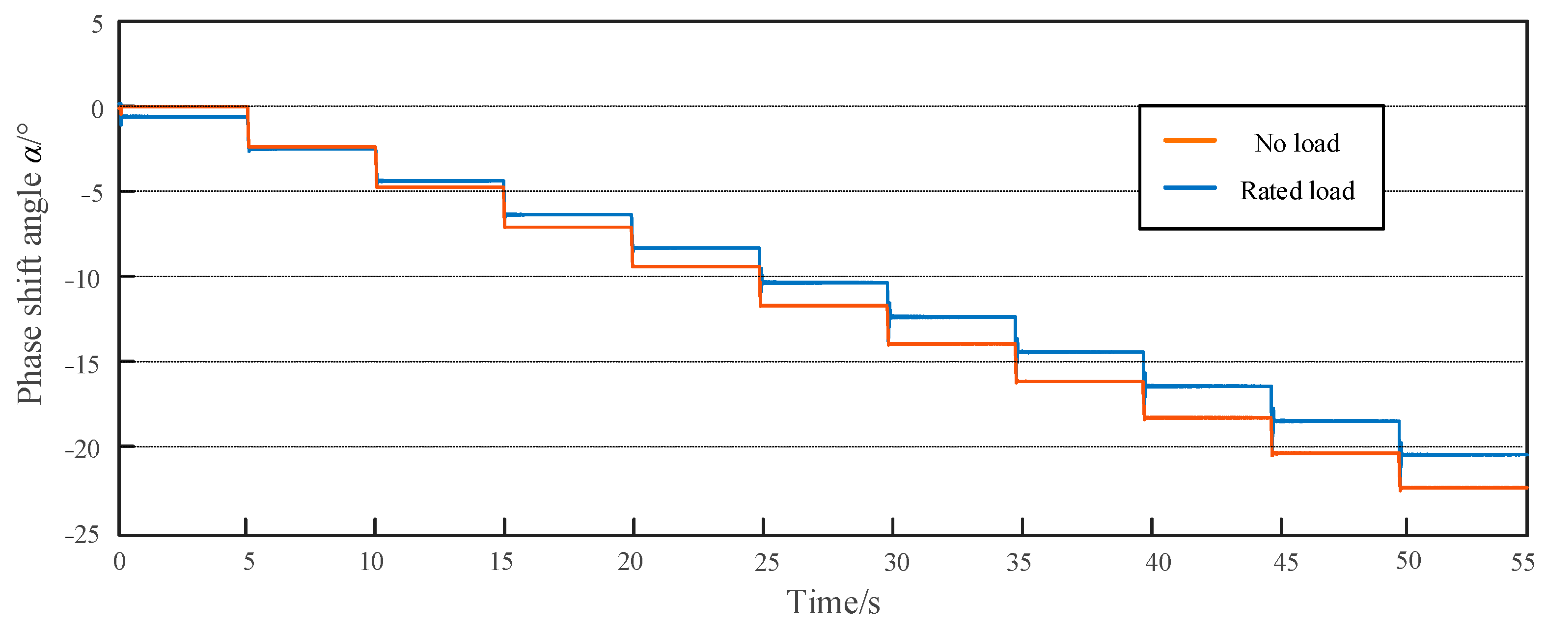
A specific calculation method for the key parameters of the load model based on PST is proposed. In addition, the number of turns of the regulating winding has been optimized to ensure that the phase shift angle corresponding to each tap is the same, which facilitates equipment design and control strategy formulation. On this basis, Simulink simulation software is used for modeling and simulation. The output performance of the PST designed is tested, and the results show that, under the condition of advanced adjustment, the maximum phase shift error is only 0.26°. Under the condition of lag adjustment, the maximum phase shift error is −0.39°. If the internal impedance of the PST is not calculated, the maximum phase shift errors of 2.67° and −2.70° will be explained, respectively. From the results, it can be seen that the parameter calculation method proposed in this article can effectively reduce the adjustment error of the PST.
(3)
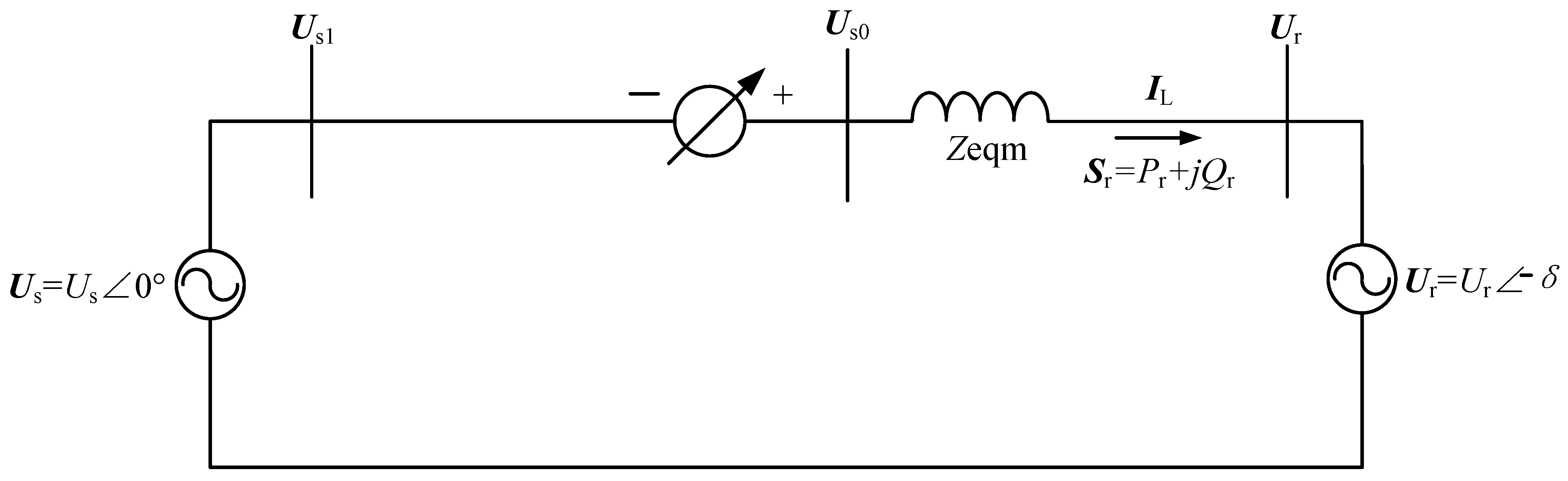
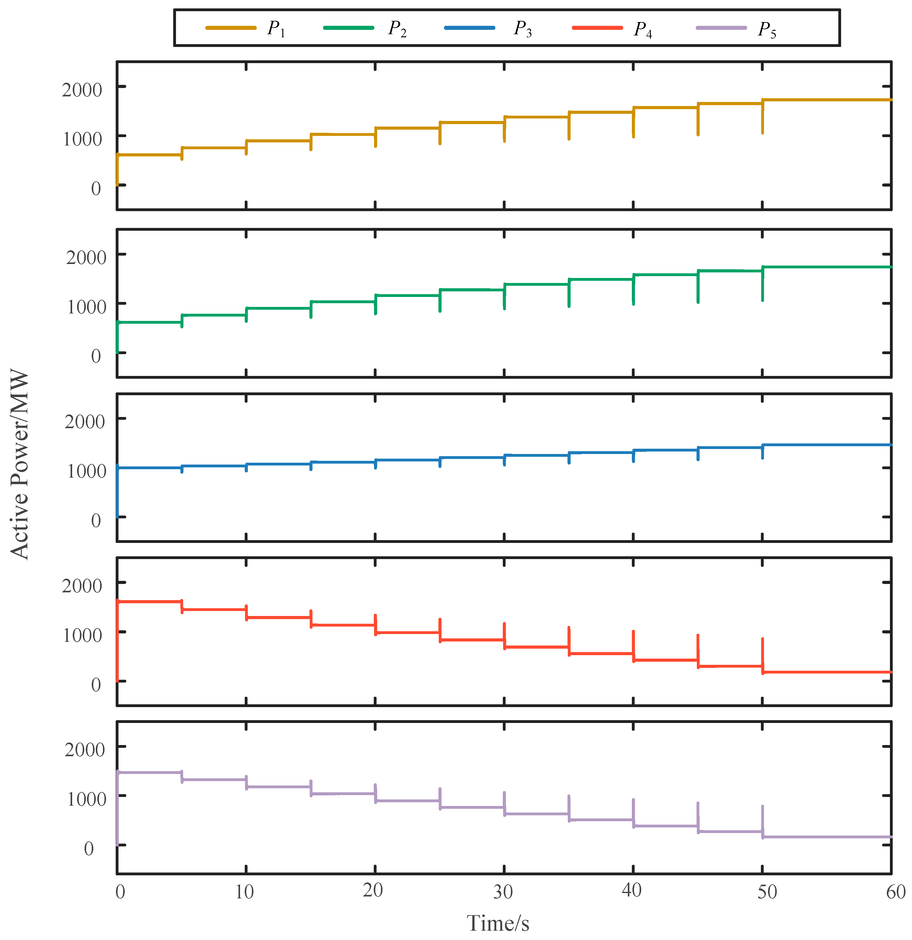
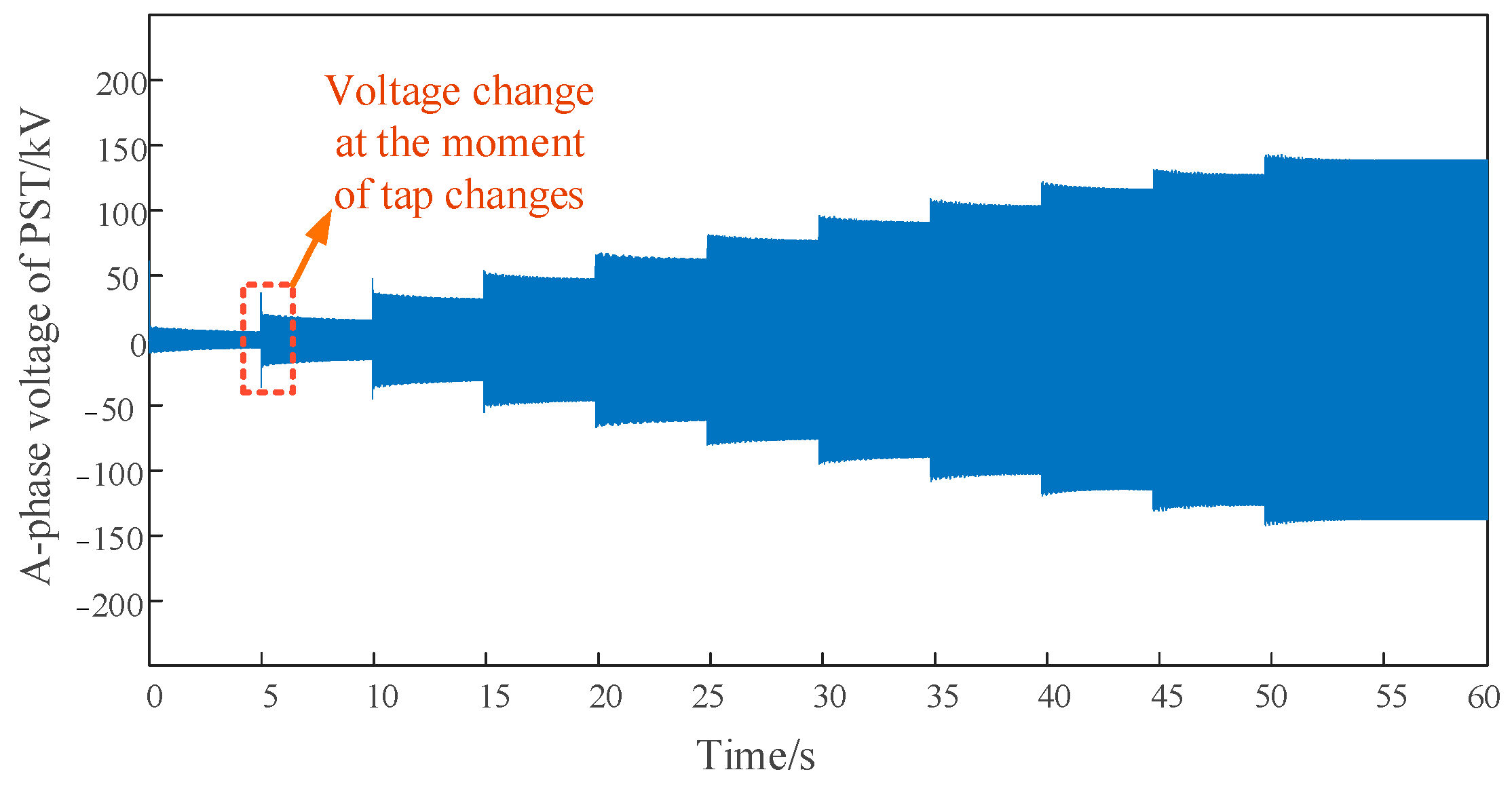
A simulation of power flow regulation is conducted in a typical 500 kV network scenario. In order to simplify the system model, the system was equivalent to a dual power system. After adding PSTs, the load rate of heavy-duty lines can be reduced, avoiding the risk of overload that may occur in DC line bipolar blocking and N-1 fault situations, thereby improving the utilization rate of light load lines. The imbalance of the line flow is greatly reduced. The application of a PST meets the needs of power grid flow optimization and helps to solve problems such as new energy transmission.

Author Contributions

Conceptualization, W.J., J.Y. and W.Z.; W.J., J.Y. and W.Z. first proposed the concept of parameter optimization for phase-shifting transformers and selected specific parameter types as the analysis objects of this article; methodology, W.J., W.Z. and H.L.; W.J., W.Z. and H.L. jointly proposed a calculation method for optimizing the number of turns by considering the existence of internal impedance in phase-shifting transformers and using the effect of power flow regulation as the goal; software and validation, W.J. and W.Z.; W.J. and W.Z. worked together to build a phase-shifting transformer model and power flow regulation network based on Simulink software, laying a solid software foundation for simulation verification; formal analysis, W.J. and J.Y.; investigation, W.J. and J.Y.; W.J. and J.Y. jointly investigated the current power flow distribution problems in the transmission network and the unclear parameter design of phase-shifting transformers, providing sufficient practical investigation and demonstration for this article; resources, J.Y.; data curation, H.L.; writing—original draft preparation, W.Z. and H.L.; writing—review and editing, W.J. and J.Y.; visualization, W.Z.; supervision, W.J. and J.Y.; project administration, J.Y.; funding acquisition, W.J., with the help of W.J., this work was supported by the Science and Technology Project of Central China branch of State Grid Corporation of China under 52140023000N, this article has obtained. All authors have read and agreed to the published version of the manuscript.

Funding

This work was supported by the Science and Technology Project of Central China branch of State Grid Corporation of China under 52140023000N.

Data Availability Statement

Data are contained within the article.

Conflicts of Interest

W.J. was employed by State Grid Corporation of China. The remaining authors declare that the research was conducted in the absence of any commercial or financial relationships that could be construed as a potential conflict of interest. The authors declare that this study received funding from State Grid Corporation of China. The funder was not involved in the study design, collection, analysis, interpretation of data, the writing of this article or the decision to submit it for publication.

References

  1. Zhang, T.; Shi, H.; Tang, T.; Ying, H.; Zou, P. Evaluation Method for Transient Reactive Power Voltage Regulation Capability of Photovoltaic Power Stations Considering Power Grid Status. In Proceedings of the 2023 8th International Conference on Power and Renewable Energy (ICPRE), Shanghai, China, 22–25 September 2023. [Google Scholar]
  2. Thwala, M.S.; Nnachi, A.F.; Moloi, K.; Akumu, A.O. The Effect of a Phase Shift Transformer for Power Flow Control. In Proceedings of the 2019 Southern African Universities Power Engineering Conference/Robotics and Mechatronics/Pattern Recognition Association of South Africa (SAUPEC/RobMech/PRASA), Bloemfontein, South Africa, 28–30 January 2019. [Google Scholar]
  3. Belivanis, M.; Bell, K.R.W. Coordination of Phase-Shifting Transformers to Improve Transmission Network Utilisation. In Proceedings of the 2010 IEEE PES Innovative Smart Grid Technologies Conference Europe (ISGT Europe), Gothenburg, Sweden, 11–13 October 2010. [Google Scholar]
  4. Babaei, A.; Ziomek, W.; Gole, A. A New Approach for the Failure Detection and the Self-Healing Process in a Solar-Based Tap Changing Transformer. In Proceedings of the 2022 International Conference on Electrical, Computer and Energy Technologies (ICECET), Prague, Czech Republic, 20–22 July 2022. [Google Scholar]
  5. Xu, G.; Qiao, C.; Wang, X.; Wu, H.; Yang, S.; Ma, L.; Zhang, Q.; Pang, G. A Multi-Layer Optimized Configuration Method for Energy Storage Device and Compensation Device on Long-Chain Power Distribution Line. In Proceedings of the 2021 8th International Conference on Electrical and Electronics Engineering (ICEEE), Antalya, Turkey, 9–11 April 2021. [Google Scholar]
  6. Fan, X.; Zhou, Y. Analysis of the Impact of Different Reactive Power Compensation Devices on Hvdc System Rectifier Station Power System Automation. In Proceedings of the 2019 4th International Conference on Power and Renewable Energy (ICPRE), Chengdu, China, 21–23 September 2019. [Google Scholar]
  7. Li, C.; Wu, Z.; Dong, L.; Liu, M.; Xiao, Y. Fast Generation of Power System Operation Modes Based on Optimal Power Flow. In Proceedings of the 2021 11th International Conference on Power and Energy Systems (ICPES), Shanghai, China, 18–20 December 2021. [Google Scholar]
  8. Chen, D.; Lu, R.; Wang, X.; Wang, Y. Power System Operation Mode Identification Method Based on Improved Clustering Algorithm. In Proceedings of the 2022 IEEE Sustainable Power and Energy Conference (iSPEC), Perth, Australia, 4–7 December 2022. [Google Scholar]
  9. ELGebaly, A.E.; Vershanskiy, E.A.; Rashitov, P.A.; Panfilov, D.I. Power Flow Control Using Transformer-Less Static Synchronous Series Compensators. In Proceedings of the 2021 3rd International Youth Conference on Radio Electronics, Electrical and Power Engineering (REEPE), Moscow, Russia, 11–13 March 2021. [Google Scholar]
  10. Xie, Q.; Wang, Y.; Zhang, W. A Review for Superconductivity-Based Voltage Sag Compensation Device. In Proceedings of the 2020 IEEE International Conference on Applied Superconductivity and Electromagnetic Devices (ASEMD), Tianjin, China, 16–18 October 2020. [Google Scholar]
  11. Sun, R.; Zhu, Z.; Wei, Z.; Sun, G.; Liao, X. Multi stage and multi-objective reactive power optimization algorithm for power systems considering UPFC. Electr. Power Eng. Technol. 2020, 39, 76–85. [Google Scholar]
  12. Ndlela, N.W.; Davidson, I.E. A Load Flow Analysis of the Southern African Power Pool Interconnections Using High Voltage Ac, High Voltage DC, and Flexible AC Transmission System. In Proceedings of the 2022 IEEE PES/IAS PowerAfrica, Kigali, Rwanda, 22–26 August 2022. [Google Scholar]
  13. Iqbal, M.N.; Mahmood, A.; Amin, A.; Arshid, H. Voltage Regulation and Power Loss Minimization by Using Unified Power Flow Control Device. In Proceedings of the 2019 International Conference on Engineering and Emerging Technologies (ICEET), Lahore, Pakistan, 21–22 February 2019. [Google Scholar]
  14. Ou, Z.; Gan, D.; Lou, Y.; Sun, Q.; Tong, Z.; Peng, S. Power Flow Equilibrium Enhancement on the Urban Power System by Unified Power Flow Controller. In Proceedings of the 2022 5th International Conference on Energy, Electrical and Power Engineering (CEEPE), Chongqing, China, 22–24 April 2022. [Google Scholar]
  15. Kong, X.; Gong, X.; Li, J.; Li, P. Analysis on the Transmission Line Power Flow Control Strategy of the Upfc Project in Western Nanjing Power Grid. In Proceedings of the 2018 International Conference on Power System Technology (POWERCON), Guangzhou, China, 6–8 November 2018. [Google Scholar]
  16. Liu, G.; Qi, W.; Huang, J.; Gong, H.; Bai, B.; Chen, Z. Overview of research on unified power flow controllers. J. Power Syst. Autom. 2018, 30, 78–86. [Google Scholar]
  17. Morrell, T.J.; Eggebraaten, J.G. Applications for Phase-Shifting Transformers in Rural Power Systems. In Proceedings of the 2019 IEEE Rural Electric Power Conference (REPC), Bloomington, MN, USA, 28–30 April 2019. [Google Scholar]
  18. Ni, P.; Zhang, J.; Liang, J.; Li, X.; Liu, Z. A Study of the Effect of Phase Shifting Transformers on Line Longitudinal Differential Protection. In Proceedings of the 2023 3rd International Conference on Energy, Power and Electrical Engineering (EPEE), Wuhan, China, 15–17 September 2023. [Google Scholar]
  19. Patel, D.; Chowdury, A. Dynamic Control and Performance of a Sen Transformer for Stabilizing an Ac Transmission System and Improved Voltage Profile. In Proceedings of the 2018 International Conference on Power, Energy, Control and Transmission Systems (ICPECTS), Chennai, India, 22–23 February 2018. [Google Scholar]
  20. Pan, Y.; Yang, W. Research on Protection System of Electronic on-Load Tap-Changers Based Sen Transformer. In Proceedings of the 2021 3rd International Conference on System Reliability and Safety Engineering (SRSE), Harbin, China, 26–28 November 2021. [Google Scholar]
  21. Siddiqui, A.S.; Khan, S.; Ahsan, S.; IKhan, M.; Annamalai. Application of Phase Shifting Transformer in Indian Network. In Proceedings of the 2012 International Conference on Green Technologies (ICGT), Trivandrum, India, 18–20 December 2012. [Google Scholar]
  22. Yu, M.; Li, F.; Li, Z.; Yuan, J.; Mei, J.; Xu, S. Principles, Topology, Applications, and Development of Phase Shifting Transformers. J. Wuhan Univ. (Eng. Ed.) 2023, 56, 1224–1237. [Google Scholar]
  23. Carlini, E.M.; Manduzio, G.; Bonmann, D. Power Flow Control on the Italian Network by Means of Phase-Shifting Transformers; CIGRE: Paris, France, 2006. [Google Scholar]
  24. Brilinskii, A.S.; Badura, M.A.; Evdokunin, G.A.; Chudny, V.S.; Mingazov, R.I. Phase-Shifting Transformer Application for Dynamic Stability Enhancement of Electric Power Stations Generators. In Proceedings of the 2020 IEEE Conference of Russian Young Researchers in Electrical and Electronic Engineering (EIConRus), St. Petersburg, Russia, 27–30 January 2020. [Google Scholar]
  25. Gude, S.; Chen, R.; Li, S.; Lang, Y. Modelling of Phase-Shifting Transformer Based on Space-Phasor Notations for the Applications in Medium Voltage Drives. In Proceedings of the 2021 IEEE Energy Conversion Congress and Exposition (ECCE), Virtual, 10–14 October 2021. [Google Scholar]
  26. Wu, L.; Yu, M.; Li, Z.; Chen, B.; Tian, C.; Kang, J. Electromagnetic Unified Power Flow Controller and Its Application in Loop Power Flow Regulation. High Volt. Technol. 2018, 44, 3241–3249. [Google Scholar]
  27. Li, Q.; Zhang, N.; Gao, S.; Liu, J.; Zhou, Q. Modeling and Application Scenario Analysis of Power Grid Phase Shifter Rtds. Power Eng. Technol. 2021, 40, 53–58. [Google Scholar]
  28. Ma, L.; Shen, X.; Dai, G. Research on Location Selection of Phase Shifting Transformers Based on Multiple Conditional Constraints. Qinghai Electr. Power 2022, 41, 58–62. [Google Scholar]
  29. Urresti-Padrón, E.; Jakubek, M.; Jaworski, W.; Kłos, M. Pre-Selection of the Optimal Sitting of Phase-Shifting Transformers Based on an Optimization Problem Solved within a Coordinated Cross-Border Congestion Management Process. Energies 2020, 13, 3748. [Google Scholar] [CrossRef]
  30. Yu, M.; Yuan, J.; Li, Z.; Li, F.; Yang, X.; Zhang, W.; Xu, S.; Mei, J. Power Flow Optimization and Economic Analysis Based on High Voltage Phase Shifting Transformer. Energies 2022, 15, 2363. [Google Scholar] [CrossRef]
  31. Fu, K.; Du, Z.; Li, F.; Li, Z.; Xia, C. Optimal allocation of phase shifting transformer with uncertain wind power based on dynamic programming. Front. Energy Res. 2023, 10, 1003315. [Google Scholar] [CrossRef]
  32. Verboomen, J.; Van Hertem, D.; Schavemaker, P.H.; Kling, W.L.; Belmans, R. Phase Shifting Transformers: Principles and Applications. In Proceedings of the 2005 International Conference on Future Power Systems, Amsterdam, The Netherlands, 16–18 November 2005. [Google Scholar]
  33. Dakhare, R.; Chandrakar, V.K. Congestion Management by Phase Shifting Transformer Using Fuzzy Logic Control. In Proceedings of the 2021 6th International Conference for Convergence in Technology (I2CT), Maharashtra, India, 2–4 April 2021. [Google Scholar]
  34. Lamas, W.d.Q. Exergoeconomic methodology applied to energy efficiency analysis of industrial power transformers. Int. J. Electr. Power Energy Syst. 2013, 53, 348–356. [Google Scholar] [CrossRef]
Figure 1. Diagram of the installation of a PST in the transmission line.
Energies 17 01622 g001
Figure 2. Topology of the dual core PST.
Energies 17 01622 g002
Figure 3. Single phase equivalent circuit of phase-shifting transformer.
Energies 17 01622 g003
Figure 4. The equivalent circuit of system with PST.
Energies 17 01622 g004
Figure 5. Synthetic phasor diagram of a PST.
Energies 17 01622 g005
Figure 6. Winding turns configuration method. (a) Traditional method (b) Optimized method.
Energies 17 01622 g006
Figure 7. 500 kV transmission lines and PST location.
Energies 17 01622 g007
Figure 8. Phase shift angle of PST output (Advancing regulation).
Energies 17 01622 g008
Figure 9. Phase shift angle of PST output (Lagging regulation).
Energies 17 01622 g009
Figure 10. Active Power of 500 kV network.
Energies 17 01622 g010
Figure 11. Voltage on the primary winding of the series transformer (A-phase).
Energies 17 01622 g011
Figure 12. Voltage fluctuation at the moment of tap change.
Energies 17 01622 g012
Table 1. 500 kV Typical Network Line Parameters.
Line ParametersL1L2L3L4L5
Rated voltage/kV525525525525525
Rated current/kA3.03.02.53.03.0
Line resistance/Ω1.271.306.982.202.93
Line reactance/Ω18.8518.8257.8518.2624.35
Transport power flow/MW64263399515701476
Line length/km70651906080
Table 2. 500 kV PST Parameters.
ParametersNumerical Value
Exciting TransformerSeries Transformer
Nominal power/MVA9821020
Rated voltage of primary winding/kV525.0112.9
Rated voltage of secondary winding/kV110.0113.0
Short circuit impedance/%11%14%
Number of adjustable levels±10
Phase shift range (Rated load)/°±20°
Phase shift range (No Load)/°±22.8°
Table 3. Adjustment performance test of PST (Advancing regulation).
Tap PositionWinding Turns Ratio DTheoretical Phase Shift Angle/°Phase Shift Angle
(No load)/°
Phase Shift Angle (Rated Load)/°
0000−0.68
+10.11422.501.76
+20.20544.884.02
+30.31767.156.13
+40.42889.398.32
+50.5331011.8110.26
+60.6361214.0412.22
+70.7331416.3714.19
+80.8241618.5216.19
+90.9151820.6218.16
+1012022.6720.09
Table 4. Power flow changes in a typical 500 kV network with PST.
Line ParametersL1L2L3L4L5
Initial active power flow/MW64263399515701465
Required phase shift angle (advance adjustment)/°6615//
Required phase shift angle (lag adjustment)/°///−10−10
Adjusted active power flow/MW1054105412101024965
Proportion of AC power received (Before regulation)/%12.1%11.9%18.8%29.6%27.6%
Proportion of AC power received (After regulation)/%19.9%19.9%23.7%19.3%17.2%
Disclaimer/Publisher’s Note: The statements, opinions and data contained in all publications are solely those of the individual author(s) and contributor(s) and not of MDPI and/or the editor(s). MDPI and/or the editor(s) disclaim responsibility for any injury to people or property resulting from any ideas, methods, instructions or products referred to in the content.

