Article

Effect of Rotational Angle of Discrete Inclined Ribs on Horizontal Flow and Heat Transfer of Supercritical R134a

1
Engineering Research Center of Metallurgical Energy Conservation and Emission Reduction, Ministry of Education, Kunming University of Science and Technology (KUST), Kunming 650093, China
2
Power China Kunming Engineering Corporation Limited, Kunming 650051, China
3
National Local Joint Engineering Research Center of Energy Saving and Environmental Protection Technology in Metallurgy and Chemical Engineering Industry, Kunming University of Science and Technology (KUST), Kunming 650093, China
*
Author to whom correspondence should be addressed.
These authors contributed equally to this work.
Energies 2024, 17(7), 1631; https://doi.org/10.3390/en17071631
Submission received: 27 February 2024 / Revised: 19 March 2024 / Accepted: 23 March 2024 / Published: 28 March 2024
(This article belongs to the Topic Advanced Heat and Mass Transfer Technologies)

Abstract

:
This work numerically studied the heat transfer and flow characteristics of supercritical R134a in horizontal pipes equipped with DDIR, considering variations in the rotation angle of DDIR. The aim is to improve the effects of the DDIR configuration on the heat transfer of supercritical flow. After validation with experimental data, the AKN model was employed to examine the effects of four sets of rotation angles (0°, 30°, 45°, and 60°) on the axial and circumferential heat transfer characteristics of DDIR horizontal tubes under the influence of strong (q1/G1 = 0.1 kJ/kg) and medium (q2/G2 = 0.056 kJ/kg) buoyancy. Results show that variations in the rotation angle do not induce significant alterations in the flow field, thus exerting minimal influence on the axial heat transfer characteristics. Meanwhile, the rotation angle determines the relative positioning of the circumferential inner wall temperatures and heat flux distribution, although the magnitude of this effect remains inconspicuous. The rotational angle parameter can be reasonably neglected in the future design and installation of heat exchangers.

1. Introduction

The Organic Rankine Cycle (ORC) has gained widespread application in supercritical systems designed to recover and utilize medium–low-temperature waste heat. When compared to traditional subcritical ORC systems, the transcritical Organic Rankine Cycle (T-ORC) demonstrates superior compatibility with heat source temperatures (as depicted in Figure 1, 5→1), lower irreversibility, and overall enhanced system performance [1,2]. Within T-ORC systems, the heat exchanger serves as a pivotal component. Depending on the specific system configuration, heat exchangers can account for 20–70% of the cost in supercritical systems [3,4]. In numerous commercial T-ORC systems, heat exchangers are primarily configured for horizontal flow [5]. Nonetheless, in horizontal flow configurations, supercritical fluids are susceptible to encountering heat transfer deterioration, resulting in local increases in wall temperature and potential thermal decomposition of the organic fluid. This poses challenges to the safety [6] and stability of the supercritical system [7,8]. Consequently, enhancing convective heat transfer in horizontal tubes under supercritical conditions becomes a critical approach to improving the heat exchange capacity of the heat exchanger and optimizing the overall efficiency of T-ORC systems.
Supercritical fluids have only a fixed critical temperatures and pressures, but they exhibit varying pseudo-critical temperatures (Tpc) corresponding to different pressures. Tpc is the temperature at which cp reaches its maximum value under a certain supercritical pressure. The region near the Tpc is known as the region of large specific heat. In this region, the thermophysical properties of the supercritical fluid are highly sensitive to temperature variations [9]. As illustrated in Figure 2, near the Tpc, even slight changes in temperature can lead to a dramatic decrease in the thermal conductivity and density of R134a. Consequently, predicting and controlling the heat transfer of supercritical working fluids inside tubes becomes challenging. On the other hand, the direction of gravity is perpendicular to the direction of the mainstream in a horizontally arranged DDIR pipe. The interaction between the temperature field and buoyancy generates secondary flows, leading to circumferential thermal unevenness [10], which increases the complexity of heat transfer process. Current research classifies heat transfer into three modes: normal heat transfer (NTH), heat transfer deterioration (HTD), and heat transfer enhancement (HTE) [11]. Scholars generally believe that HTD occurs when there is a dramatic increase in wall temperature accompanied by a decrease in the heat transfer coefficient. In horizontal pipes, buoyancy is considered the primary factor contributing to HTD. Fluids at higher temperatures and lower densities tend to flow downward, while fluids at lower temperatures and higher densities tend to flow upward. Consequently, heat accumulation at the top cannot be promptly carried away, causing the Tw to rise and resulting in HTD [12]. However, in vertical tubes, the mechanism by which HTD occurs is different from that in horizontal tubes. According to the turbulent shear stress theory, the coupling effect of buoyancy and flow acceleration leads to different heat transfer modes. When these forces act in the same direction (i.e., vertical upward flow), HTD occurs. Conversely, when the forces act in opposite directions (i.e., vertical downward flow), HTE occurs [13,14].
HTE is advantageous for improving system efficiency and reducing system costs. Consequently, research on heat transfer enhancement in horizontal flow has garnered significant attention from scholars worldwide. For example, enhanced surfaces, porous media, phase-change devices, nanofluids, flexible seals, flexible complex seals, vortex generators, and ultra-high thermal conductivity composite materials are widely used in HTE technologies [15]. Enhanced surfaces have received increased attention in high-energy efficiency systems due to their ability to enhance fluid turbulence, disturb boundary layers, increase heat transfer area, and generate secondary flows [16]. Among various enhanced surfaces heat transfer technologies, using ribs to roughen the inner wall is widely employed in supercritical heat exchangers. In contrast to a smooth tube (ST), Ackerman et al.’s experiment [17] examined the flow heat transfer properties of supercritical water in an internal ribbed tube (IRT). They concluded that IRT exhibit enhanced heat transfer capabilities. Li et al. [18] studied the heat transfer performance of supercritical CO2 in the micro-fin tube (MFT) and found that the cooling heat transfer coefficient of MFT increased by 12–39% compared to ST. In recent years, some scholars have utilized organic working fluids to investigate the flow heat transfer in ribbed tubes. Wang et al. [19] conducted experiments showing that supercritical R134a has varying levels of enhancement effects on the bottom and top of MFT compared to ST. In another study by Wang et al. [20], they analyzed the flow heat transfer characteristics of IRT and ST, yielding similar conclusions. Their results showed that heat transfer coefficients at the top and bottom of IRT are 4.61 and 1.4 times higher than those of ST, respectively. Guo et al. [21] were the first to propose the field synergy theory, in which they emphasized that enhancing the coordination of the flow and temperature field can improve the heat transfer. Based on this theory, Meng et al. [22] analyzed the temperature and flow field of circular pipes, and pointed out that multiple longitudinal vortices provide an ideal flow pattern for enhanced heat transfer. Subsequently, they developed the DDIR tube. Li et al. [23] conducted an experimental and simulation in which DDIR improved the heat transfer by 100–120% compared with ST at a Reynolds number between 15,000 and 60,000. Wang et al. [24] investigated the effects of parameters such as Re, rib height (e), and number of ribs (n). In other studies of DDIR, Zheng [25], Ariwibowo [26], Song [27], and Zhang [28] all indicated that DDIR has a better/superior heat transfer performance. The above studies on DDIR were all conducted under subcritical conditions, whilst Yuan et al. [29] were the first to apply DDIR to supercritical conditions. They studied the rib geometrical parameters of rib height, rib spacing, and inclination angle on the supercritical CO2 heat transfer, and gave the optimal rib spacing and rib height parameters within the research range. In our previous work [30], some rib parameters (such as rib spacing, rib height, and inclination angle) were studied on the flow heat transfer of supercritical R134a in a DDIR tube, but the effect of the rotation angle was not considered.
As mentioned above, the unique stratification phenomenon in horizontal tubes suggests that the  α  may influence the heat transfer coefficient of DDIR pipes. However, this aspect has not been covered in previous studies. Therefore, in order to further enhance the study on the impact of rib arrangement on the horizontal flow heat transfer of supercritical R134a, it is necessary to analyze the impacts of varied  α  on the flow and heat transfer properties of DDIR horizontal tubes.

2. Numerical Modeling

2.1. Control Equations

During the numerical solution process, the governing equations for mass, energy and momentum are all given in Favre-averaged form. The governing equations are solved as follows.
Continuity equation:
x j ( ρ ¯ μ ~ j ) = 0
Momentum equation:
x j ρ ¯ μ ~ j u ¯ j = P x i + x j σ ¯ i j ρ u i u j ¯ + ρ g i
Energy equation:
x j ρ ¯ u ~ j h ~ = x j λ c p h ~ x j
Equations (1)–(3), where “-” and “~” denote the scalar time and Favre-average values, respectively, represent the mass, momentum, and energy governing equations. The term  σ ¯ i j  in Equation (2) is determined by the following Equations (4) and (5):
σ ¯ i j = μ u ~ i x j + u ~ j x i 2 δ i j 3 · u ~ k x k
ρ u i u j ¯ = 2 μ t S ~ i j 1 3 u ~ k x k δ i j 2 3 ρ ¯ k δ i j
In Equation (5)
S ~ i j = 1 2 u ~ i x j + u ~ j x i

2.2. Turbulence Models

The selection of appropriate turbulence models is crucial for accurately predicting heat transfer in supercritical flows and closing the aforementioned control equations. Operating conditions, fluid selection, tube geometry, and other factors can significantly influence the choice of turbulence models. The numerical simulation of supercritical horizontal flow using various turbulence models, such as the SST k-ω model, RSM model, Realizable k-ε model, Standard k-ε model, and RNG k-ε model. In the context of horizontal flow under supercritical conditions, researchers such as Tian et al. [31] have compared their experimental data with calculated values from multiple turbulence models. They found that the AKN model exhibited the most favorable predictive performance for the convective heat transfer of supercritical R134a in horizontal tubes.
The AKN model substitutes the friction velocity (μτ) with the Kolmogorov velocity scale (με), thus accommodating the near-wall and low Reynolds number effects. Researchers such as K. Abe [32] found that the damping function can better simulate the mixed boundary layer driven by buoyancy. Additionally, the AKN model is suitable for conditions where significant variations exist in velocity and temperature fields within the heated wall surface. Therefore, compared to the vertical flow of supercritical fluids, the AKN turbulence model is more applicable to horizontal flow with more complex flow and temperature fields. With the introduction of DDIR, more pronounced changes in temperature and velocity gradients near the wall are expected. Consequently, the following formulas will be used to solve the transport equations for k and ε in the numerical model of this study, validating the applicability of the AKN turbulence model.
( ρ ¯ u ~ j k ) x j = x j μ + μ t σ k k x j ρ u i u j ¯ u ~ i x j ε
( ρ ¯ u ~ j ε ) x j = x j μ + μ t σ ε ε x j C ε 1 ρ u i u j ¯ u ~ i x j C ε 2 f ε ε 2 k
f μ = 1 e y / 14 2 1 + 5 R t 3 / 4 e R t 200 2
f ε = 1 e y / 3.1 2 1 0.3 e R t 6.5 2
In Equations (8) and (9),  y * = ρ d u ε / μ R t = ρ k 2 / ( u ε ) u ε = ( u ε / ρ ) 0.25 . The constants  C ε 1 C ε 2 C μ σ k  and  σ ε  in the above equation are 1.5, 1.9, 0.09, 1.4, and 1.4, respectively [32].

2.3. Model Validaton

Since there are only a few experiments on horizontally arranged DDIR tubes in the public literature, and these data were obtained under subcritical conditions. Therefore, the numerical model validation will be carried out in the two following parts to ensure the reliability of the model. Firstly, the geometric model under subcritical conditions is validated. Once the accuracy of the geometric model is confirmed, the turbulence model will be validated in the supercritical condition to ensure that the entire model is accurate and reliable. The boundary condition settings of the DDIR horizontal tube are illustrated in Figure 3. The heating section is configured as a constant heat flux wall, with non-heating sections at the outlet and inlet and the wall is specified as a non-slip inner wall. Considering the buoyancy, the gravity acceleration is set to 9.81 m/s2. Use UDF to import the thermophysical properties of R134a into FLUENT during the calculation process. The maximum error of UDF calculation cp is less than 0.3%, and other thermophysical properties are less than 0.4% when compared with the NIST Standard Reference Database [33]. Convergence is considered during the calculation process when the residuals of monitored factors, such as the outlet mass flow rate and temperature, reach a value below 10−6.
Figure 4a depicts the comparison of the Nu and f calculated by the geometric model established in this study with the experimental data from Meng et al. [22], utilizing subcritical water as the working fluid. In their experiments, the tube had a length of 2 m, with a  d o of 20 mm, and a  d i of 19 mm. The rib spacing was 12 mm, rib height 0.85 mm, and rib length 6 mm. The inclination angle was set at 45°, and the  R e  ranged from 500 to 15,000. The comparison results reveal that the simulated values align closely with the experimental data, with maximum errors of Nu/Pr1/3 and f both below 10%. This indicates that the established geometric model is suitable for subsequent research. However, since the experiment was conducted under subcritical conditions and the experimental working fluid differs significantly from the organic working fluid R134a used in the study, turbulence model validation is required as a supplement.
When performing turbulence model validation, the experimental data come from the heat transfer characteristics experiment of supercritical R134a in a 10.3 mm inner diameter and 2.5 m tube length horizontal tube conducted by Tian and her colleagues [34]. Their experimental parameter range is P = 4.13–4.87 MPa, G = 400–1500 kg/m2s, q = 20–100 kW/m2. Turbulence model validation is depicted in Figure 4b. Apart from certain deviations near the inlet and outlet sections, the AKN model demonstrates a more accurate prediction of the heat transfer situation in the DDIR horizontal tube. There was also an analysis of the sensitivity of thermal boundary conditions to adjust the simulated process closer to the experimental settings. The constant current heating typically employed in experiments is akin to uniform internal volume heat source heating in the simulation process. Therefore, the numerical results are compared with two different thermal boundary conditions: uniform heat flux boundary (constant qw,o) and uniform internal heat source boundary (constant qave). The numerical calculation demonstrates insensitivity to the thermal boundary conditions, as evidenced by the nearly identical temperature distribution along the inner wall estimated for both thermal boundary conditions. Hence, the experiment can be accurately reproduced using the constant heat flow density boundary condition.

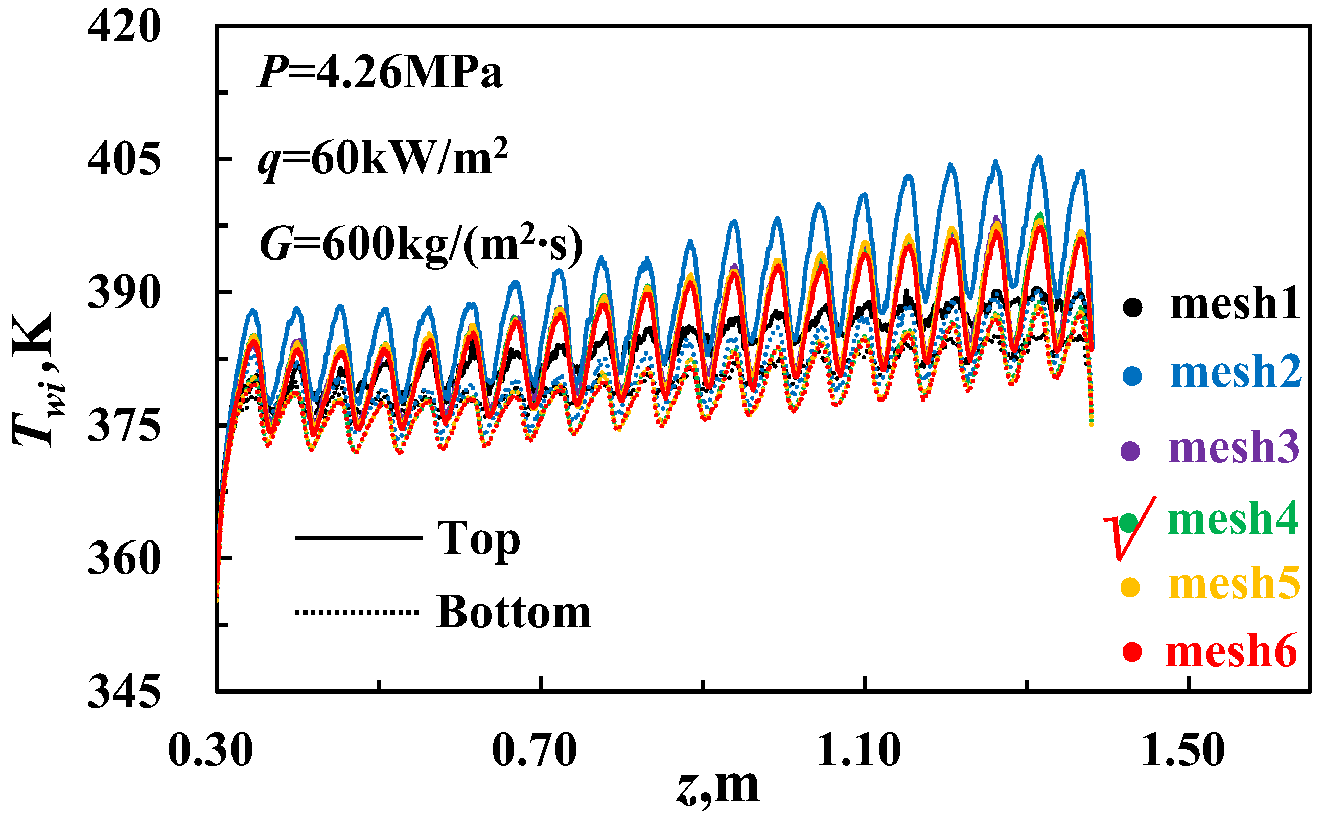
2.4. Grid Independence Validation

This study employs ANSYS ICEM 18.0 [23] software for meshing. Given that DDIR constitutes an irregular geometry, non-structural meshing is carried out on the horizontal DDIR tubes. Due to symmetry, only half of the mesh is validated and analyzed to save computational resources. Six representative grid test groups were established to validate grid independence. Table 1 shows the detailed grid validation. Building upon mesh 1, mesh 2 reduces the distance between the first layer mesh and the wall to ensure y+ < 1, guaranteeing that at least 20 meshes are arranged in the laminar flow bottom layer and buffer layer to capture the intensity changes in supercritical R134a near the wall. Additionally, to accurately simulate conjugate heat transfer in the horizontal tube, the grid size of the fluid–solid coupling interface is increased by a ratio of 1.1–1.2 times until the grid size reaches d/70 and remains constant. Mesh 3 refines the local mesh based on mesh 2, focusing on the specific areas of interest for increased resolution. On the other hand, mesh 4 refines the global mesh based on mesh 2, aiming to improve the overall mesh quality across the entire domain. Both mesh 5 and mesh 6 involve comprehensive mesh refinement, covering both global and local regions. However, mesh 6 features a higher degree of refinement compared to mesh 5.
The results of grid independence validation are presented in Figure 5. It is observed that the impact of global grid densification on the calculation accuracy outweighs that of local densification. Consequently, considering both the calculation accuracy and computational resource efficiency, mesh 4 was selected as the preferred meshing method for the DDIR horizontal tube.

3. Results and Discussion

As depicted in Figure 6, the angle at which the DDIR horizontal tube rotates in the circumferential direction with the main flow direction (i.e., axial direction) as the rotation axis is denoted as the rotation angle  α  (counterclockwise is illustrated in Figure 6 as an example). When the rotation angle varies between 0° and 90°, the DDIR within the horizontal tube will assume different arrangements. Thus, to further investigate the impact of DDIR layout on flow and heat transfer characteristics in horizontal tubes, four groups of typical rotation angles were established as research objects: 0° (traditional DDIR tube), 30°, 45°, and 60°. Under conditions of strong buoyancy, with P = 4.6MPa and Tin = 343K, the parameter is q1/G1 = 0.1 kJ/kg (i.e., q1= 60 kW/m2, G1 = 600 kg/m2·s). For medium buoyancy conditions, the working parameter is q2/G2 = 0.056 kJ/kg (i.e., q1 = 45 kW/m2, G1 = 800 kg/m2·s).

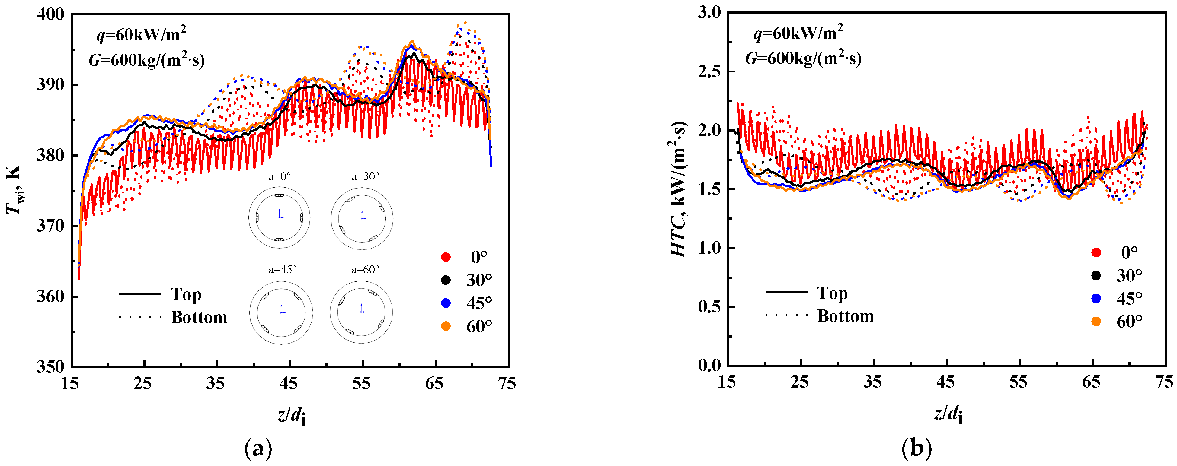
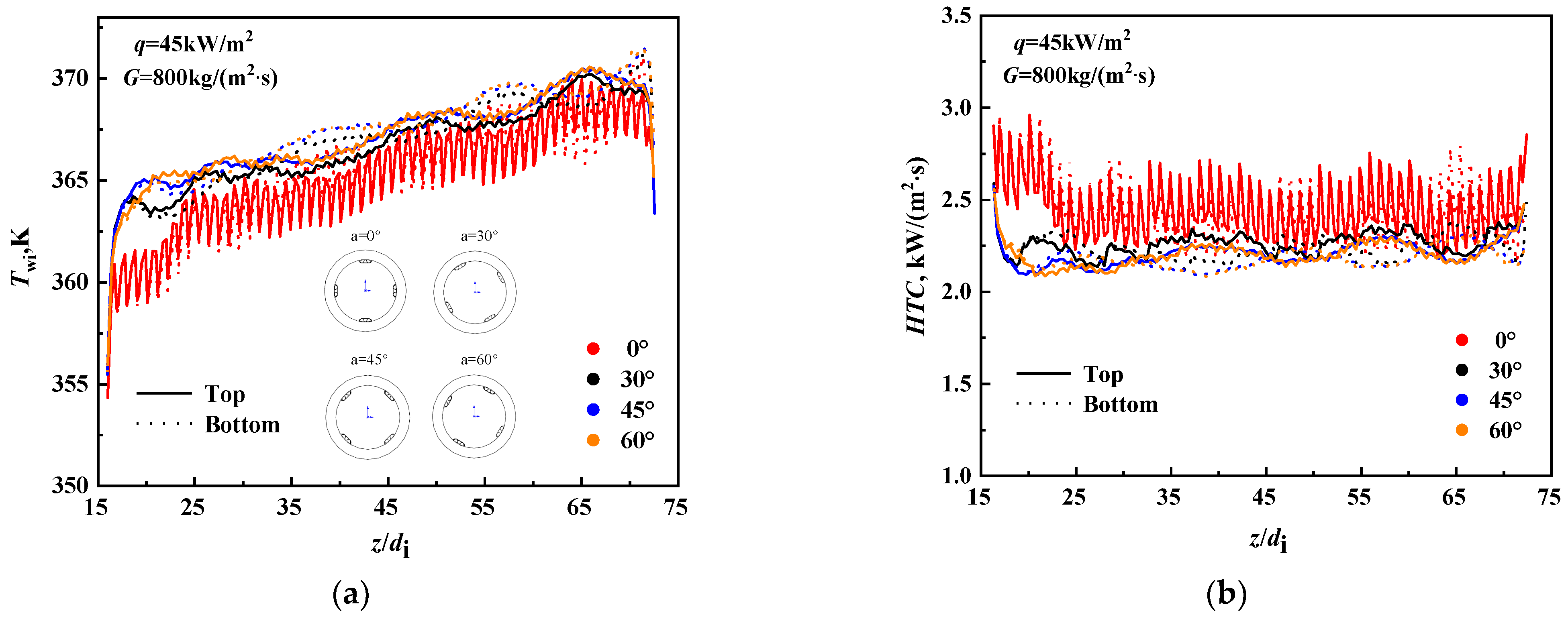
3.1. Influence on Axial Heat Transfer Characteristics

When the supercritical fluid flows in a horizontally arranged tube, secondary flow is induced by the strong buoyancy. This secondary flow leads to the deterioration of mixed convection heat transfer, resulting in the uneven distribution of circumferential  T w and  q . Consequently, the heat transfer capacity at the top is not as effective as that at the bottom [12,35,36]. However, as depicted in Figure 7, the DDIR horizontal tube does not exhibit similar heat transfer characteristics. This suggests that the conventional heat transfer rules governing traditional supercritical horizontal flow are evidently no longer applicable. In the DDIR horizontal tube, the phenomenon of circumferential thermal unevenness still exists. However, the temperature distribution along the inner wall is no longer simply higher at the top and lower at the bottom as in traditional supercritical horizontal flow. In some positions of the heating section, the  T w at the bottom is higher than at the top. Additionally, another noteworthy phenomenon is observed: the  T w distribution along the top and bottom of the DDIR horizontal tube fluctuates periodically, and the maximum temperature difference in the circumferential direction occurs in the area where three wall temperature peaks are located at the bottom.
At the same time, under strong buoyancy conditions (q/G = 0.1 kJ/kg), changes in rotation angle have little impact on the axial heat transfer characteristics of the DDIR horizontal pipe. When the rotation angle is 30°, the  T w distribution along the top and bottom is almost the same as at 0°, resembling that of a traditional DDIR horizontal tube. As the rotation angle increases, the temperature distribution along the inner wall slightly increases. However, when it increases to 45°, changes in the rotation angle do not cause significant alterations in wall temperature and HTC. The above phenomenon indicates that, under strong buoyancy conditions, the  α  affects the axial heat transfer capacity of the DDIR horizontal pipe. However, as the angle increases, the degree of influence diminishes, eventually reaching a stable state.
As depicted in Figure 8, when q/g is reduced to 0.056 kJ/kg, the Twi and HTC of DDIR horizontal tubes with rotation angles of 30°, 45°, and 60° resemble those of DDIR  α  = 0°. The fluctuation of Twi decreases significantly. Moreover, the previously pronounced periodic fluctuations in wall temperature along the process have nearly disappeared, leading to significantly improved heat transfer and thermal stability. Additionally, under medium buoyancy conditions, changes in rotation angle did not have a significant impact on the axial heat transfer of the DDIR horizontal tube. The effect of the rotation angle on heat transfer still exhibited a similar pattern to that observed under strong buoyancy conditions. The above phenomenon demonstrates that the influence of changes in rotation angle on the heat transfer capacity along the tube is closely linked to the strength of the buoyancy. When compared with strong buoyancy, different patterns of influence are observed under the condition of medium buoyancy. In summary, the analysis of results under medium buoyancy and strong buoyancy shows that changes in rotation angle will not have a significant impact on the axial heat transfer capacity.

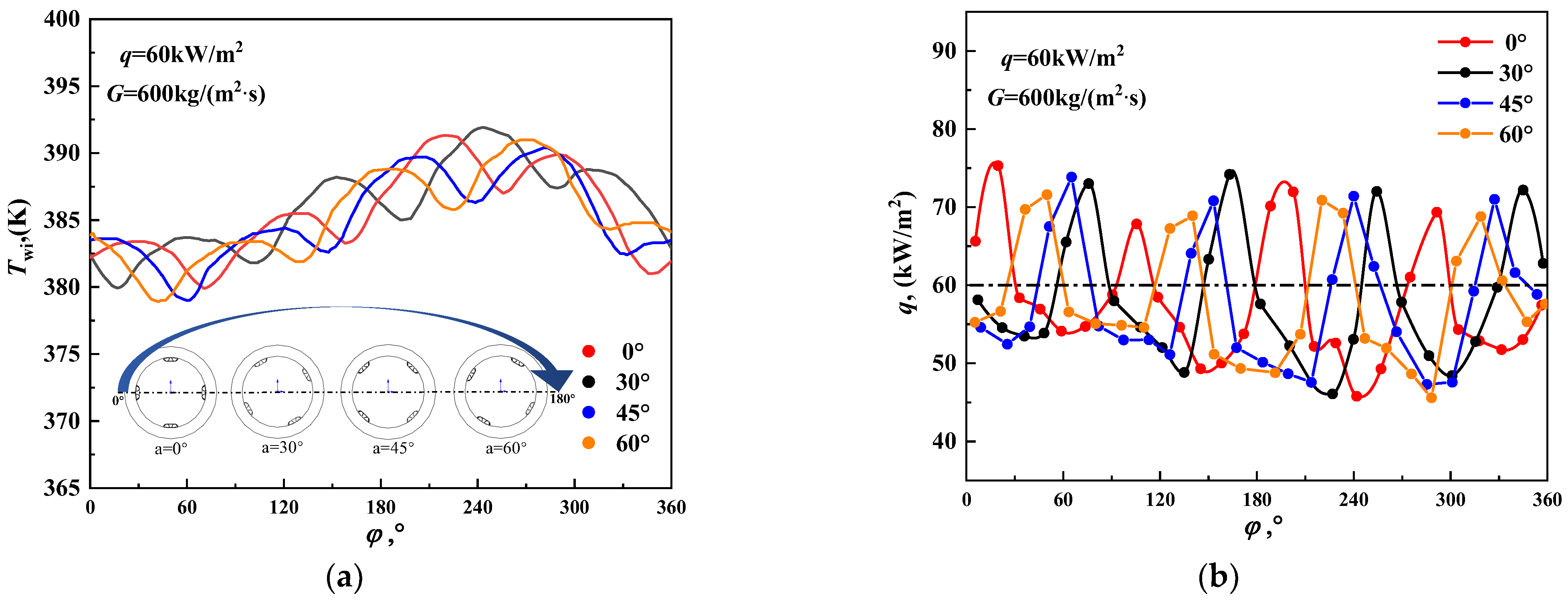
3.2. Influence on Circumferential Heat Transfer Characteristics

Compared to the horizontal smooth tubes, DDIR horizontal tubes have a very different circumferential wall temperature distribution pattern. Firstly, the positioning of the ribs determines the circumferential wall temperature peak rather than the top and bottom positions. The highest Twi occurs at the middle of the rib position, while the lowest  T wi occurs between two adjacent ribs. Secondly, the circumferential  T wi distribution of the DDIR horizontal tube fluctuates periodically, with the period of fluctuation depending on the number of rib groups, regardless of whether ribs are dispersed on the cross-section.
Figure 9 indicates that the rotation angle affects the DDIR horizontal tube’s circumferential heat transfer properties. The change in rotation angle does not have a significant influence on the fluctuation period and magnitude of the circumferential inner wall temperature. Since the DDIR horizontal tube corresponding to the four rotation angles has four sets of double inclined inner ribs, both the inner wall temperature and heat flux exhibit four distinct fluctuation periods in circumferential distribution. Moreover, the magnitude difference between the peaks of the inner wall temperature and heat flux fluctuations corresponding to the four rotation angles is not significant. However, due to the influence of changes in the circumferential position of the discrete ribs, the circumferential position (circumferential angle) of the inner wall temperature and inner wall heat flux fluctuation peaks of the DDIR horizontal tube corresponding to different rotation angles is approximately equal to the difference between the rotation angles. In summary, the change in rotation angle has no significant impact on the circumferential heat transfer characteristics of the DDIR horizontal tube. To further explore the influence mechanism of the rotation angle on the supercritical R134a horizontal flow heat transfer, conducting an in-depth analysis of the flow field and temperature field under the effect of different rotation angles is necessary.

3.3. Analysis of Impact Mechanism

The influence of the rotation angle on the local (z/di = 39) flow field and temperature field of R134a under strong buoyancy is shown in Figure 10. Four sets of discrete double inclined internal ribs induce a progressively developing vortex within the tube, extending from the wall towards the center of the main flow. Additionally, the flow velocity gradually increases from the wall towards the center of the bulk flow. From the flow field cloud diagram, it is evident that, despite the continuous variation in rotation angle, the central vortex within the bulk flow consistently remains tangent to the line connecting the top and bottom ribs at 0° (i.e., depicted by the black solid line in Figure 10a). Moreover, the tangent point is situated near the intersection with the rotation axis (i.e., dashed line in Figure 10a). In addition, as the rotation angle increases, no significant changes are found in the cross-sectional flow field form and flow velocity distribution, indicating that changes in rotation angle have little impact on the development of the flow field in the DDIR horizontal tube. Since the flow field distribution form of the DDIR cross-section has a significant influence on the temperature field distribution, changes in rotation angle do not have a significant impact on the temperature field distribution. In summary, since changes in the DDIR rotation angle do not have a significant impact on the flow field in the tube, the  T w and HTC distribution along the top and bottom and the circumferential inner wall temperature and heat flux distribution are not sensitive to changes in the rotation angle.

4. Conclusions

In this work, under the specified working conditions, P = 4.6 MPa, Tin = 343 K, q ranging from 45 kW/m2 to 800 kW/m2, and G ranging from 600 kg/(m2·s) to 800 kg/(m2·s), a numerical simulation study was conducted. After the comparison and validation with experimental data, a numerical simulation study was conducted using a low Reynolds number AKN turbulence model to investigate the impact of axial rotation angle changes on the convection heat transfer characteristics of supercritical R134a in a horizontal DDIR tube. The main findings are summarized as follows:
  • Under the influence of strong buoyancy, a noticeable circumferential thermal unevenness persists in the DDIR horizontal tube. However, the temperature distribution of the top and bottom inner walls exhibits alternating periodic fluctuations, differing from the traditional supercritical horizontal flow. As the buoyancy weakens, the temperature fluctuation amplitude of the top and bottom inner walls in the DDIR horizontal tube decreases.
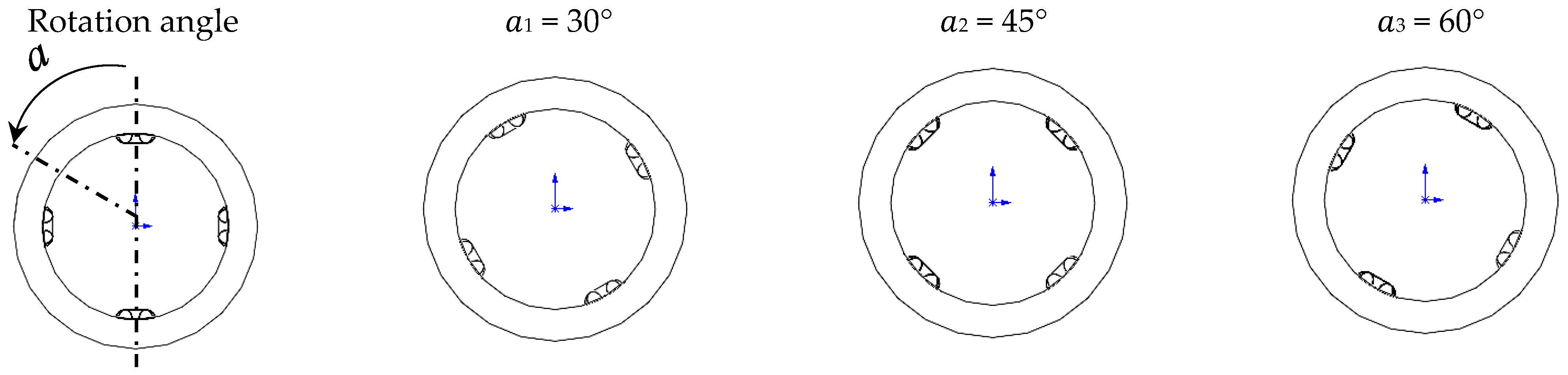
  • The number of rib groups in the circumferential direction of the DDIR horizontal tube determines the fluctuation period of the circumferential inner wall temperature and inner wall heat flux. However, the change in the rotation angle of the inclined discrete ribs along the axial direction does not have a significant impact on the axial heat transfer or the distribution of circumferential wall temperature and inner wall heat flux in the DDIR horizontal tube.
  • The change in the rotation angle of the inclined discrete ribs does not significantly affect the supercritical R134a flow field in the DDIR horizontal tube. Its impact is mainly observed in the position of the circumferential inner wall temperature and the inner wall heat flux peak. The relative positions between the peaks depend on the differences in rotation angles.

Author Contributions

Conceptualization, Z.L.; Methodology, G.Y.; Software, J.T.; Validation, J.T.; Investigation, G.Y.; Writing—original draft, G.Y. and J.T.; Writing—review & editing, Z.L.; Supervision, Z.L. All authors have read and agreed to the published version of the manuscript.

Funding

This research was funded by National Natural Science Foundation of China (grant No. 52176073), Yunnan Major Scientific and Technological Projects (grant No. 202302AG050011), and Yunnan Applied Basic Research Project (grant No. 202301AW070014).

Data Availability Statement

Data are contained within the article.

Conflicts of Interest

Author Junrui Tang was employed by the company Power China Kunming Engineering Corporation Limited. The remaining authors declare that the research was conducted in the absence of any commercial or financial relationships that could be construed as a potential conflict of interest.

Nomenclature

c p s p e c i f i c   h e a t , k J / ( k g · K ) b b u l k
d t u b e   d i a m e t e r , m m h h e a t e d
e r i b   h e i g h t , m m i i n n e r
f f r i c t i o n   f a c t o r i 1 insulation section I
G m a s s   f l u x , k g / m 2 s i 2 insulation section II
g g r a v i t a t i o n a l   a c c e l e r a t i o n , m / s 2 in i n l e t
H T C h e a t   t r a n s f e r   c o e f f i c i e n t , W / m 2 K o o u t e r
h e n t h a l p y , J / k g p c p s e u d o c r i t i c a l
k t u r b u l e n t   k i n e t i c   e n e r g y , m 2 · s 2 w w a l l
N u N u s s e l t   n u m b e r w i w a l l   i n s i d e
L t u b e   l e n g t h , m m Acronyms
n n u m b e r   o f   r i b s A K N A b e , K o n d o h , a n d   N a g a n o   t u r b u l e n c e   m o d e
P p r e s s u r e , M P a D D I R d i s c r e t e   d o u b l e   i n c l i n e d   r i b s
P r P r a n d t l   n u m b e r R N G R e n o r m a l i z a t i o n - g r o u p   t u r b u l e n c e   m o d e
p r i b   p i t c h , m m R S M R e y n o l d s   s t r e s s   e q u a t i o n   m o d e l
q   h e a t   f l u x , k W / m 2 S S T s h e a r   s t r e s s   t r a n s p o r t   t u r b u l e n c e   m o d e l
R e R e y n o l d s   n u m b e r UDFuser-defined functions
S e n t r o p y , k J / ( k g · K ) Greek symbols
T t e m p e r a t u r e , K α r i b   r o t a t i o n   a n g l e , °
u v e l o c i t y , m / s ρ d e n s i t y , k g / m 3
w r i b   w i d t h , m m λ t h e r m a l   c o n d u c t i v i t y , W / ( m · K )
y + n o n - d i m e n s i o n a l   w a l l   d i s t a n c e μ d y n a m i c   v i s c o s i t y , P a s
z a x i a l   d i s t a n c e φ c i r c u m f e r e n t i a l   a n g l e , °
Subscripts ε t u r b u l e n t   d i s s i p a t i o n   r a t e , s
a v e a v e r a g e ω s p e c i f i c   d i s s i p a t i o n   r a t e , s 1

References

  1. Liu, P.; Shu, G.; Tian, H.; Feng, W.; Shi, L.; Wang, X. Experimental study on transcritical Rankine cycle (TRC) using CO2/R134a mixtures with various composition ratios for waste heat recovery from diesel engines. Energy Convers. Manag. 2020, 208, 112574. [Google Scholar] [CrossRef]
  2. Buonomano, A.; Calise, F.; Palombo, A.; Vicidomini, M. Energy and economic analysis of geothermal–solar trigeneration systems: A case study for a hotel building in Ischia. Appl. Energy 2015, 138, 224–241. [Google Scholar] [CrossRef]
  3. Walraven, D.; Laenen, B.; D’Haeseleer, W. Economic system optimization of air-cooled organic Rankine cycles powered by low-temperature geothermal heat sources. Energy 2015, 80, 104–113. [Google Scholar] [CrossRef]
  4. Yu, G.; Shu, G.; Tian, H.; Wei, H.; Liang, X. Multi-approach evaluations of a cascade-Organic Rankine Cycle (C-ORC) system driven by diesel engine waste heat: Part B-techno-economic evaluations. Energy Convers. Manag. 2016, 108, 596–608. [Google Scholar] [CrossRef]
  5. Wang, D.; Dai, X.; Tian, R.; Shi, L. Experimental investigation of the heat transfer of supercritical R134a in a horizontal micro-fin tube. Int. J. Therm. Sci. 2019, 138, 536–549. [Google Scholar] [CrossRef]
  6. Akbar, S.; Vaimann, T.; Asad, B.; Kallaste, A.; Sardar, M.U.; Kudelina, K. State-of-the-Art Techniques for Fault Diagnosis in Electrical Machines: Advancements and Future Directions. Energies 2023, 16, 6345. [Google Scholar] [CrossRef]
  7. Irriyanto, M.Z.; Lim, H.-S.; Choi, B.-S.; Myint, A.A.; Kim, J. Thermal stability and decomposition behavior of HFO-1234ze(E) as a working fluid in the supercritical organic Rankine cycle. J. Supercrit. Fluids 2019, 154, 104602. [Google Scholar] [CrossRef]
  8. Gunawan, R.; Irriyanto, M.Z.; Cahyadi, H.S.; Irshad, M.; Lim, H.-S.; Choi, B.-S.; Kwak, S.-K.; Myint, A.A.; Kim, J.-H. Mechanism of thermal decomposition of HFO-1234ze(E) under supercritical fluid conditions. J. Supercrit. Fluids 2020, 160, 104792. [Google Scholar] [CrossRef]
  9. Yildiz, S.; Groeneveld, D.C. Diameter effect on supercritical heat transfer. Int. Commun. Heat Mass Transf. 2014, 54, 27–32. [Google Scholar] [CrossRef]
  10. Yu, S.; Li, H.; Lei, X.; Feng, Y.; Zhang, Y.; He, H.; Wang, T. Influence of buoyancy on heat transfer to water flowing in horizontal tubes under supercritical pressure. Appl. Therm. Eng. 2013, 59, 380–388. [Google Scholar] [CrossRef]
  11. You, T.; Pan, Y.; Zhai, Y.; Wang, H.; Li, Z. Heat transfer in a U-bend pipe flow at supercritical pressure. Int. J. Heat Mass Transf. 2022, 191, 122865. [Google Scholar] [CrossRef]
  12. Yu, S.; Li, H.; Lei, X.; Feng, Y.; Zhang, Y.; He, H.; Wang, T. Experimental investigation on heat transfer characteristics of supercritical pressure water in a horizontal tube. Exp. Therm. Fluid Sci. 2013, 50, 213–221. [Google Scholar] [CrossRef]
  13. Aicher, T.; Martin, H. New correlations for mixed turbulent natural and forced convection heat transfer in vertical tubes. Int. J. Heat Mass Transf. 1997, 40, 3617–3626. [Google Scholar] [CrossRef]
  14. Jackson, J.D. Fluid flow and convective heat transfer to fluids at supercritical pressure. Nucl. Eng. Des. 2013, 264, 24–40. [Google Scholar] [CrossRef]
  15. Khaled, A.; Siddique, M.; Nazrulislam, N.; Boukhary, A.Y. Recent advances in heat transfer enhancements: A review report. Int. J. Chem. Eng. 2010, 2010, 106461. [Google Scholar]
  16. Kukulka, D.J.; Smith, R.; Fuller, K.G. Development and evaluation of enhanced heat transfer tubes. Appl. Therm. Eng. 2011, 31, 2141–2145. [Google Scholar] [CrossRef]
  17. Ackerman, J. Pseudoboiling heat transfer to supercritical pressure water in smooth and ribbed tubes. J. Heat Transf. 1970, 92, 490–497. [Google Scholar] [CrossRef]
  18. Lee, H.-S.; Kim, H.-J.; Yoon, J.-I.; Choi, K.-H.; Son, C.-H.J.H.; Transfer, M. The cooling heat transfer characteristics of the supercritical CO2 in micro-fin tube. Heat Mass Transf. 2012, 49, 173–184. [Google Scholar] [CrossRef]
  19. Wang, D.; Tian, R.; Zhang, Y.; Li, L.; Shi, L. Experimental comparison of the heat transfer of supercritical R134a in a micro-fin tube and a smooth tube. Int. J. Heat Mass Transf. 2019, 129, 1194–1205. [Google Scholar] [CrossRef]
  20. Wang, D.; Tian, R.; Li, L.; Dai, X.; Shi, L. Heat transfer of R134a in a horizontal internally ribbed tube and in a smooth tube under super critical pressure. Appl. Therm. Eng. 2020, 173, 115208. [Google Scholar] [CrossRef]
  21. Guo, Z.Y.; Li, D.Y.; Wang, B.X. A novel concept for convective heat transfer enhancement. Int. J. Heat Mass Transf. 1998, 41, 2221–2225. [Google Scholar] [CrossRef]
  22. Meng, J.-A.; Liang, X.-G.; Li, Z.-X. Field synergy optimization and enhanced heat transfer by multi-longitudinal vortexes flow in tube. Int. J. Heat Mass Transf. 2005, 48, 3331–3337. [Google Scholar] [CrossRef]
  23. Li, X.-W.; Meng, J.-A.; Guo, Z.-Y. Turbulent flow and heat transfer in discrete double inclined ribs tube. Int. J. Heat Mass Transf. 2009, 52, 962–970. [Google Scholar] [CrossRef]
  24. Wang, Y.; Zhou, B.; Liu, Z.; Tu, Z.; Liu, W. Numerical study and performance analyses of the mini-channel with discrete double-inclined ribs. Int. J. Heat Mass Transf. 2014, 78, 498–505. [Google Scholar] [CrossRef]
  25. Zheng, N.; Liu, W.; Liu, Z.; Liu, P.; Shan, F. A numerical study on heat transfer enhancement and the flow structure in a heat exchanger tube with discrete double inclined ribs. Appl. Therm. Eng. 2015, 90, 232–241. [Google Scholar] [CrossRef]
  26. Ariwibowo, T.H.; Miyara, A.J.R. Thermal characteristics of slinky-coil ground heat exchanger with discrete double inclined ribs. Resources 2020, 9, 105. [Google Scholar] [CrossRef]
  27. Song, W.M.; Meng, J.A.; Li, Z.X. Numerical study of air-side performance of a finned flat tube heat exchanger with crossed discrete double inclined ribs. Appl. Therm. Eng. 2010, 30, 1797–1804. [Google Scholar] [CrossRef]
  28. Zhang, X.; Cheng, L. Heat Transfer and Fluid Flow Characteristics of Microchannel with Discrete Double Inclined Ribs on Sidewalls. Heat Transf. Eng. 2024, 1–17. [Google Scholar] [CrossRef]
  29. Yuan, N.; Bi, D.; Zhai, Y.; Jin, Y.; Li, Z.; Wang, H. Flow and heat transfer performance of supercritical pressure carbon dioxide in pipes with discrete double inclined ribs. Int. J. Heat Mass Transf. 2020, 149, 119175. [Google Scholar] [CrossRef]
  30. Tang, J.; Yuan, N.; Zhai, Y.; Li, Z. Effect of discrete inclined ribs on flow and heat transfer of supercritical R134a in a horizontal tube. J. Supercrit. Fluids 2023, 200, 105980. [Google Scholar] [CrossRef]
  31. Tian, R.; Wei, M.; Dai, X.; Song, P.; Shi, L. Buoyancy effect on the mixed convection flow and heat transfer of supercritical R134a in heated horizontal tubes. Int. J. Heat Mass Transf. 2019, 144, 118607. [Google Scholar] [CrossRef]
  32. Abe, K.; Kondoh, T.; Nagano, Y. A new turbulence model for predicting fluid flow and heat transfer in separating and reattaching flows—II. Thermal field calculations. Int. J. Heat Mass Transf. 1995, 38, 1467–1481. [Google Scholar] [CrossRef]
  33. Lemmon, E.W.; Huber, M.L.; McLinden, M.O. Transport Properties, v. 9. NIST Standard Reference Database 23. 2010. Available online: https://www.nist.gov/system/files/documents/srd/REFPROP8_manua3.htm (accessed on 6 December 2023).
  34. Tian, R.; Wang, D.; Zhang, Y.; Ma, Y.; Li, H.; Shi, L. Experimental study of the heat transfer characteristics of supercritical pressure R134a in a horizontal tube. Exp. Therm. Fluid Sci. 2019, 100, 49–61. [Google Scholar] [CrossRef]
  35. Adebiyi, G.A.; Hall, W.B. Experimental investigation of heat transfer to supercritical pressure carbon dioxide in a horizontal pipe. Int. J. Heat Mass Transf. 1976, 19, 715–720. [Google Scholar] [CrossRef]
  36. Lei, X.; Li, H.; Dinh, N.; Zhang, W. A study of heat transfer scaling of supercritical pressure water in horizontal tubes. Int. J. Heat Mass Transf. 2017, 114, 923–933. [Google Scholar] [CrossRef]
Figure 1. Temperature–entropy diagram of T-ORC system.
Energies 17 01631 g001
Figure 2. Thermophysical properties of R134a at 4.1 MPa.
Energies 17 01631 g002
Figure 3. DDIR horizontal tube boundary condition settings. Reprinted from [30], Pages No.3, Copyright (2023), with permission from Elsevier.
Energies 17 01631 g003
Figure 4. Comparison of the experimental values and calculated values, (a) geometric model, (b) turbulence model. Reprinted from [30], Pages No.4, Copyright (2023), with permission from Elsevier.
Energies 17 01631 g004
Figure 5. DDIR horizontal tube grid independence validation.
Energies 17 01631 g005
Figure 6. Schematic diagram of working conditions with different rotation angles.
Energies 17 01631 g006
Figure 7. The distribution of (a) wall temperature and (b) heat transfer coefficients along the top and bottom under the strong buoyancy (q/G = 0.1 kJ/kg).
Energies 17 01631 g007
Figure 8. The distribution of (a) wall temperature and (b) heat transfer coefficients along the top and bottom under the medium buoyancy (q/G = 0.056 kJ/kg).
Energies 17 01631 g008
Figure 9. Distribution of the circumferential inner (a) wall temperature and (b) wall heat flux at z/di = 39 under strong buoyancy influence.
Energies 17 01631 g009
Figure 10. Comparison of the effects of different rotation angles (z/di = 39) on the (a) flow field distribution and (b) temperature field distribution under strong buoyancy conditions.
Energies 17 01631 g010aEnergies 17 01631 g010b
Table 1. Details of grid validation test.
Mesh No.Global Mesh SizeLocal Grid Size Total   Mesh   Grids   ( × 10 6 )Maximum Wall Temperature Deviation Compared to Mesh 6
Max (mm)FactorMax Ribs (mm)First Grid Layer Height (mm)
12.01.50.50.05 (y+ > 1)1.57−14.8‰
22.01.50.50.0035 (y+ < 1)2.4120.4‰
32.01.50.20.00356.186.4‰
41.31.30.50.003510.433.6‰
51.21.20.10.003514.83.2‰
61.01.00.10.003019.010
Reprinted from [30], Pages No.5, Copyright (2023), with permission from Elsevier.
Disclaimer/Publisher’s Note: The statements, opinions and data contained in all publications are solely those of the individual author(s) and contributor(s) and not of MDPI and/or the editor(s). MDPI and/or the editor(s) disclaim responsibility for any injury to people or property resulting from any ideas, methods, instructions or products referred to in the content.

