Article

Thermodynamic Analysis and Comparison of Power Cycles for Small Modular Reactors

1
Department of Innovative Technologies for High-Tech Industries, National Research University “Moscow Power Engineering Institute”, 111250 Moscow, Russia
2
Department of Thermal Power Plants, National Research University “Moscow Power Engineering Institute”, 111250 Moscow, Russia
*
Author to whom correspondence should be addressed.
Energies 2024, 17(7), 1650; https://doi.org/10.3390/en17071650
Submission received: 7 March 2024 / Revised: 26 March 2024 / Accepted: 27 March 2024 / Published: 29 March 2024
(This article belongs to the Section B4: Nuclear Energy)

Abstract

:
Small nuclear power plants can provide a stable, carbon-free energy supply to civil infrastructure and industrial enterprises in remote regions isolated from unified energy systems. More than 70 projects of small modular reactors are currently being developed by IAEA member countries; several low-power power units are already supplying thermal and electrical energy to consumers. One of the main limitations standing in the way of widespread dissemination of this technology is the high specific capital cost of a low-power nuclear power plant; therefore, new scientific and technical solutions are needed in this industry. Increasing the thermodynamic efficiency of power cycles of small modular reactors can become a driver for reducing the cost of supplied electrical energy. This paper presents the results of a comprehensive thermodynamic analysis of existing and promising power cycles for small modular reactors. In addition to traditional steam power cycles, cycles using non-traditional working fluids, including carbon dioxide, freons, and helium cycles, are considered. Optimal sets of thermodynamic parameters were determined to ensure maximum net efficiency of electricity production. For water-cooled reactor plants, a maximum efficiency of 33.5% at an initial temperature of 300 °C could be achieved using a steam turbine cycle. It was revealed that for reactor plants with liquid metal and liquid salt coolant in the range of initial temperatures above 550–700 °C, the maximum thermal efficiency was provided by the Brayton recompression cycle with a carbon dioxide coolant: the net electrical efficiency exceeded the level of steam turbine plants, with intermediate superheating of the steam, and could reach a value of 49.4% at 600 °C. This makes the use of these cycles promising for low-power nuclear power plants with a high initial temperature. In small gas-cooled reactor plants with a helium coolant, the use of a binary cycle consisting of a helium Brayton cycle and a steam-powered Rankine cycle provided an efficiency of 44.3% at an initial helium temperature of 700 °C and 52.9% at 1000 °C. This was higher than in the Brayton cycle with a recuperator, with a minimum temperature difference in the heat exchanger of 20 °C: the efficiency was 40.2% and 52%, respectively. Also, the transition to power cycles with non-traditional working fluids will lead to a change in the operating conditions of turbomachines and heat exchangers.

1. Introduction

1.1. Energy Supply Problems in Remote Regions

The active industrial development in many countries is the main driver of growth in global energy consumption. The global challenge facing the energy sector is to ensure sustainable humankind development through resource conservation while reducing emissions of toxic substances and greenhouse gases into the environment to prevent irreversible climate change.
Currently, the pathway in energy sector transformation is to increase the share of energy generation based on non-carbon energy sources. This trend is due on the one hand to the continuous depletion of hydrocarbon fuel reserves and on the other hand to the continuous tightening of environmental regulations for industrial enterprises.
Another important trend in the energy sector is the development of decentralized systems for the energy supply of regions isolated from unified energy systems. According to [1], the rate of introduction of new distributed generation capacities worldwide will exceed that of centralized power plants. This is mostly due to the increased efficiency of small power generation technologies with steady reductions in specific capital costs.
One of the main obstacles in the development of isolated regions is the lack of developed infrastructure, primarily in the energy sector [2]. Insufficient power supply and isolated electric systems limit the potential for implementing various energy-intensive industrial and infrastructure projects: from mining and metallurgy to consumer supply and seawater desalination [3,4].
The huge capital investment requirements in the construction of power units and the cost of the transportation of energy resources in remote regions call for the development of new, efficient, stand-alone, small power units. Constructing small nuclear power plants (SNPPs) is a promising direction in the development of energy infrastructure in isolated locations [5]. Such plants can provide a stable and carbon-free consumer power supply, while the low refueling frequency (e.g., for RITM-200N type reactors—maximum once every 5 years) ensures high operational independence [6]. In addition to power generation, the centralized heat supply of cities and enterprises, seawater desalination, and carbon-free hydrogen production can be implemented at such power units, which, combined, can meet a wide range of industrial needs of regions isolated from unified energy systems.
The small nuclear power plant operation is based on the use of small modular reactors (SMRs) characterized by relatively low power (generally, up to 300 MWe) and designed using modular solutions providing capacity expansion potential and small footprints. Theoretically, such reactors could be manufactured and assembled directly at factories and transported to the operation site in a ready-to-use state, which would reduce capital investments for the construction of new power units in areas with underdeveloped infrastructure. This makes distributing small nuclear power promising, especially for power supply to regions isolated from unified energy systems.

1.2. Current State of SMR Projects

Currently, more than 70 projects of various designed small modular reactors [7] are underway worldwide. Work on SMRs is included in the nuclear energy development strategies of many IAEA member countries.
Currently, the largest number of developments in the field of small modular reactors are underway in Russia, China, and the USA. This line of development is included in the list of initiatives for the socio-economic development of the Russian Federation until 2030, “New Nuclear Energy, including small nuclear reactors for remote regions”, and the State Corporation Rosatom is engaged in the development of this line. Thus, in May 2020, the world’s only floating nuclear cogeneration plant at the Akademik Lomonosov power unit with KLT-40S reactor units [8] was commissioned. The plant power output reaches up to 70 MW, with a maximum heat load of 169 MW; it supplies power to the island network of the Chaun-Bilibino node in Chukotka Autonomous Okrug and heat to the city of Pevek. It should be noted that KLT-40S-type reactors are a modified version of marine pressurized water-type reactors for nuclear icebreakers and lighter carriers, which can also power domestic RITM-type reactors. Currently, the State Atomic Energy Corporation “Rosatom” is implementing a project to build a 106 MW land-based SNPP in the Ust-Yana region of Yakutia based on RITM-200N reactor units, with launch scheduled for 2027.
Since 2003, China has been operating the gas-cooled reactor HTR-10 with thermal power of 10 MW developed at Tsinghua University [9]. Based on this reactor design, a fourth-generation higher-power (250 MW) helium reactor, HTR-PM, was subsequently developed and has been operating at Shidaowan NPP (nuclear power plant) since 2021 [10]. In 2021, construction of the water-cooled modular reactor pilot project ACP100 with electrical power of 125 MW was also commenced at Changjiang NPP. The ACP100 SMR was identified as a “key project” in China’s Twelfth Five-Year Plan and was developed based on the larger ACP1000 reactor.
The high-temperature test reactor (HTTR), built by the Oarai Research and Development Center of the Japan Atomic Energy Agency, is Japan’s first high-temperature, gas-cooled reactor. The reactor’s thermal power is 30 MW. The outlet helium temperature of the reactor is 850 °C in nominal operation mode and 950 °C in high-temperature experimental operation mode. The Japan Atomic Energy Agency, together with Mitsubishi Heavy Industries, plans to subsequently establish a pilot project for hydrogen production based on the high-temperature reactor [11].
An Argentine nuclear power unit with the CAREM25 SMR has been under construction since 2014. The pilot reactor will offer thermal power of 100 MW with a water coolant temperature of 326 °C [12].
In early 2023, the U.S. Nuclear Regulatory Commission licensed the SMR project by NuScale. The VOYGR water-cooled SMR with a thermal power of 250 MW is being developed as part of the Carbon Free Power Project. The construction of a 462 MWe nuclear power plant with six NuScale small modular reactors was scheduled at the Idaho National Laboratory, but the project was canceled in November 2023 due to a significant rise in project costs [13].
To date, despite the large number of SMR projects under development, these systems have not come into common use. This is due to the existing trend to reduce the share of the atomic energy sector in some countries in recent decades and the high costs of projects: currently, most commercially implemented SMR projects are partially or fully subsidized by governments.
Effective commercial implementation of SNPP projects requires addressing a number of scientific and engineering issues, which remain an urgent challenge to this date. High specific capital investments per unit capacity of SNPP result in a rise in the cost of electricity supply and, as a consequence, the deterioration of the technology competitivity compared with conventional methods of energy supply. In this regard, when developing design solutions and cycle designs for small modular reactors, one of the key criteria is the final cost of equipment to enable the successful commercialization of projects.

1.3. Engineering Level of SMR Projects

Existing SMR design and construction projects cover a wide range of reactor types:
-
pressurized, water-cooled reactors (PWRs) and boiling water reactors (BWRs);
-
high-temperature, gas-cooled reactors (HTGRs) with a helium coolant;
-
liquid metal fast reactors (LMFRs);
-
molten salt reactors (MSRs).
The modular reactor type largely defines the maximum coolant operating temperature level and, consequently, the energy efficiency of the thermodynamic cycle. Figure 1 specifies the coolant operating temperatures at the core outlet for existing designs of various types of small modular reactors. Most of the SMR projects are currently at the stage of conceptual design and evaluation of the efficiency of investments; research is being conducted on hydrodynamics, heat transfer, and nuclear physics for new types of reactors. Table 1 shows a list of small modular reactor projects under operation, construction, and final design. BREST-OD-300 was added to the list because it has an electrical capacity of 300 MW, but the reactor is not positioned as a modular-type reactor.
In water-cooled reactors, the reactor outlet coolant temperature ranges from 100 °C (RUTA-70) to 345 °C (IMR); the average water coolant outlet temperature for existing projects is 291 °C. DHR400, HAPPY200, TEPLATOR, and RUTA-70 reactors are designed for centralized heat supply; therefore, they produce heat energy with low working fluid temperatures.
Liquid metal-cooled reactors have a higher output temperature level: the average value at the outlet is 515 °C and can reach 650 °C (Westinghouse LFR), which allows for a high level of thermodynamic cycle energy efficiency. Higher temperatures can be achieved in small modular liquid salt reactors—the average is 700 °C; however, 800 °C can be reached.
The highest temperatures are achieved in the helium-cooled HTGR—the average value at the outlet is 820 °C; however, 950 °C can be reached (MHR-T). There is also the South African project AHTR-100 with a helium temperature limit of 1200 °C. Such high values are achieved through the use of an inert non-reactive helium coolant and ceramic-coated globular graphite fuel elements, with further temperature increase limited due to the structural properties of the materials of the reactor vessel and other reactor plant components.
Energy generation is one of the main purposes of most designed small modular reactors. The parameters of the process of nuclear fuel fission heat energy conversion into electric power generation depend on the thermodynamic cycle design; the cycle design is chosen depending on the reactor type and specifications.
Since SMR performances vary widely, efficient power generation requires the consideration of various options for power cycle configuration. Currently, the most common for nuclear power units are Rankine steam turbine cycles, where the thermal energy of the nuclear fuel fission reaction is used to produce the steam driving the turbine unit. However, despite the common use of this technology, the level of energy efficiency of such cycles depends mostly on the initial coolant temperature. Thus, for PWR-type reactors where the coolant temperature does not exceed 350 °C, the cycle design generally adopts a steam-power cycle with dry saturated steam downstream of the steam generator, and the final efficiency remains relatively low. For reactor plants with liquid metal and liquid salt coolants, the power cycle can be designed with steam reheating upstream and downstream of the high-pressure turbine, similarly to that of conventional thermal power plants.
Recently, a large number of studies have focused on the potential use of not only conventional steam-turbine Rankine cycles but also more thermodynamically efficient (at high temperatures) closed gas-turbine Brayton cycles with supercritical carbon dioxide [15,16,17]. Some small modular reactor designs (Westinghouse LFR, SSTAR, Energy Well, and some others) involve supercritical carbon dioxide (S-CO2) as a coolant in the recompression cycle for power generation. Due to the fact that the critical temperature of carbon dioxide is close to the ambient temperature and is 31 °C, the working fluid can be compressed in the cycle compressor close to the saturation line with reduced energy consumption. In addition, due to the high fluid density, the turbo machine dimensions are significantly reduced, which has a positive effect both on the SNPP power unit footprint and capital intensity.
Currently, small high-temperature, gas-cooled reactors are designed mainly for helium coolants, which, after heating in the core, operate in the integrated Brayton cycle (in some projects—in the cycle with heat recovery) or transfer heat to the steam power circuit. Helium is a chemically inert gas and does not affect the neutron balance, nor does it react with any reactor island materials. Since the coolant temperature in the circuit remains relatively high in the Brayton helium cycle, an additional steam–water circuit can be added to the cold source of the helium circuit, which will significantly increase the power generation efficiency, or high-temperature heat can be used for various technological processes.
The wide operating temperature range has resulted in a variety of cycle designs for SMRs. Conventional steam turbine plants do not always provide the highest thermodynamic efficiency of power generation, and the cycle design choice will largely depend on both the reactor type and the level of initial cycle parameters. Due to the fact that many research and development efforts in the field of small nuclear power plants are currently being conducted, the development and study of effective power generation methods become an urgent challenge. Paper [18] considers some cycles for the NuScale small modular reactor, including the regenerative steam–water Rankine cycle and cycles using unconventional coolants such as carbon dioxide, ammonia, and ethanol.
This paper presents the results of thermodynamics studies of promising cycles for power units with small modular reactors. For different reactor unit types with a wide range of operating parameters, key energy efficiency indicators are determined to further provide recommendations on the choice of the cycle design structure and parameters.

2. Research Object

The research objects in this paper are power cycles for small modular reactors of various types:
  • water-cooled small modular reactors with a coolant temperature up to 350 °C;
  • liquid metal-cooled small modular reactors with a temperature up to 650 °C;
  • reactors with liquid salt coolant where the temperature can reach 800 °C;
  • high-temperature, gas-cooled reactors with helium coolant temperatures from 700 °C to 1000 °C.
For nuclear power plants with these reactor unit types, this paper considers several variants of power cycle implementation:
  • regenerative organic Rankine cycles (ORCs) with freon coolant;
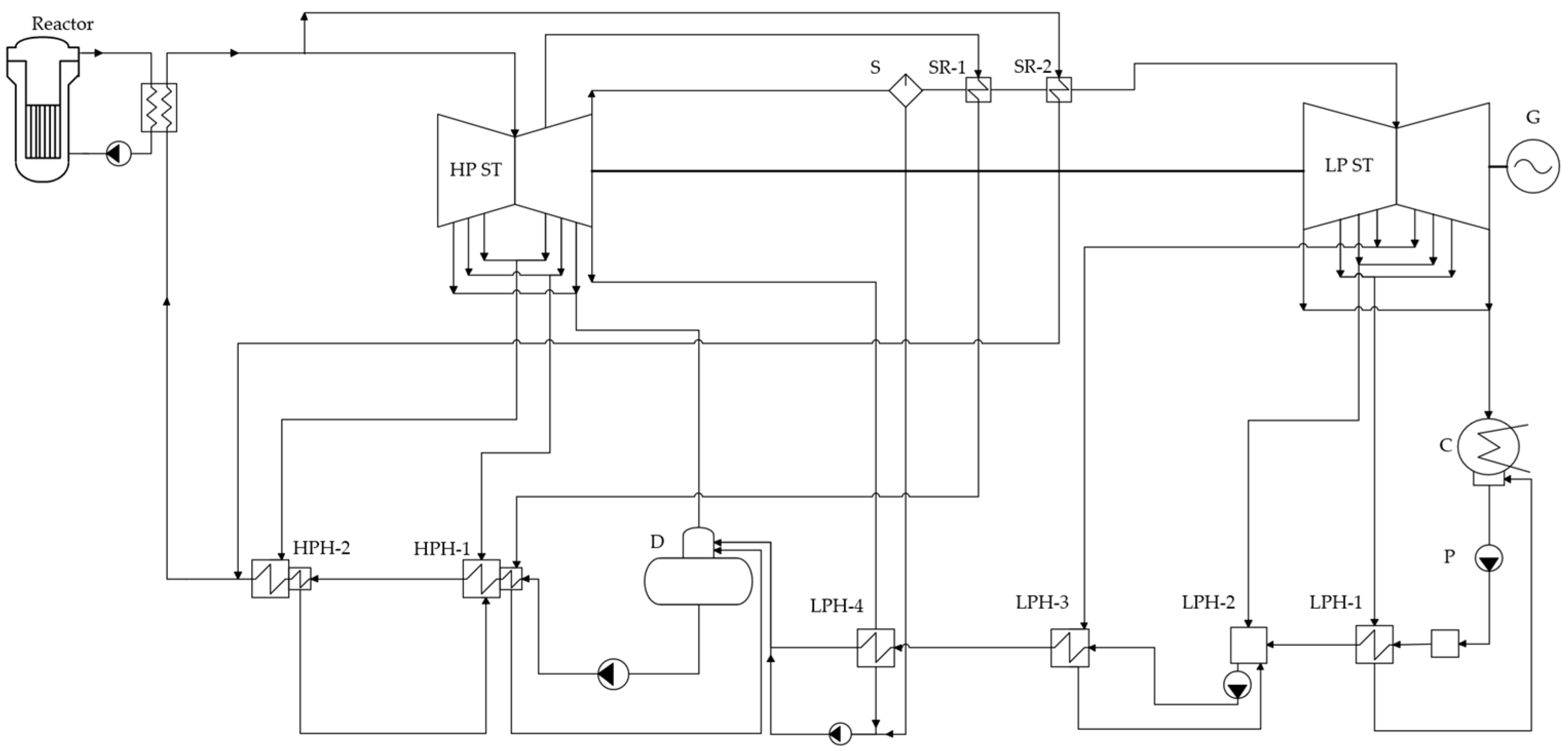
  • steam turbine Rankine cycles with an intermediate steam separator and reheater;
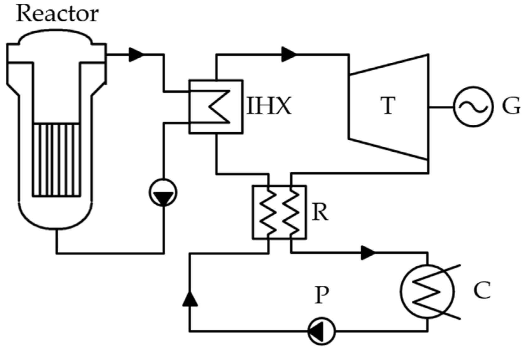
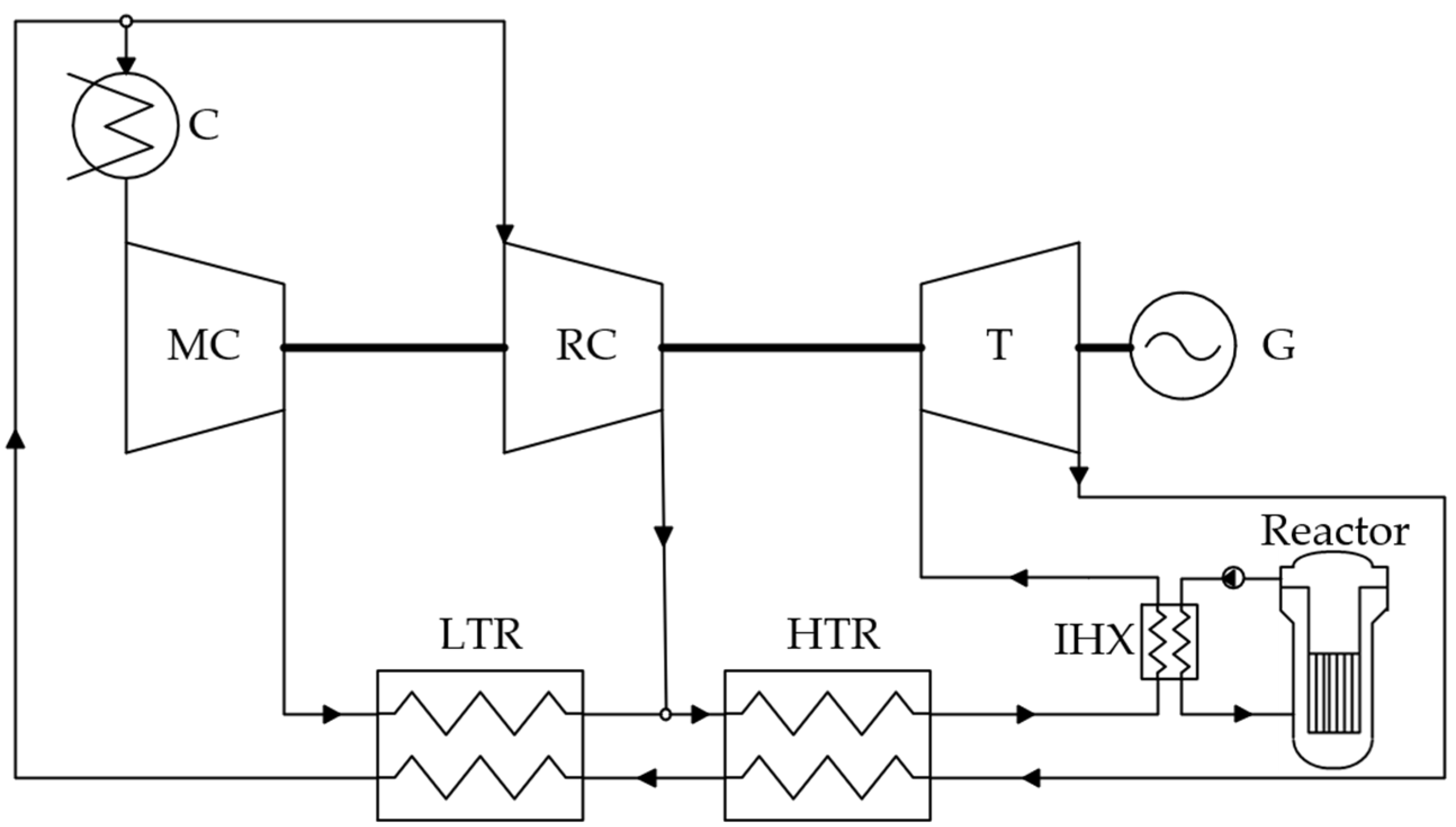
  • carbon dioxide Brayton cycles with recompression;
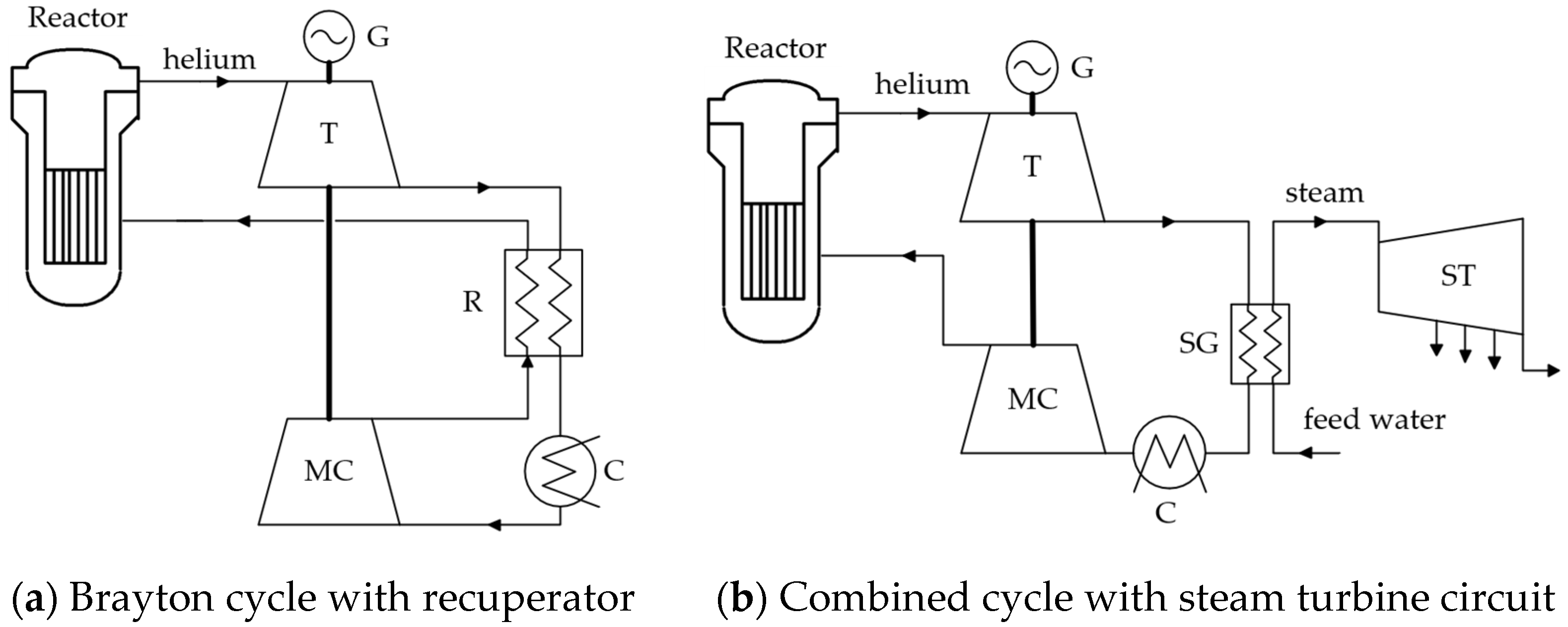
  • helium Brayton cycles with regeneration;
  • helium Brayton cycles with an additional steam turbine circuit.
Currently, the most common NPP power generation design is the one using steam–water Rankine cycles. Here, the primary coolant transfers heat energy in steam generators for water coolant heating and evaporation. Due to engineering constraints, the NPP steam turbine plant, in contrast with that of TPPs (thermal power plants), operates typically without steam reheating in the reactor, which requires moisture separation between the high- and low-pressure STU (steam turbine unit) sections and the working fluid reheating with the main steam.
Figure 2 shows the schematic cycle design diagram for NPPs with a steam turbine unit. The cycle operates as follows. Water coolant evaporated in the steam generator is fed to the turbine consisting of high- and low-pressure sections, and a part of this steam is immediately withdrawn for live steam reheating. Upon entering the turbine, the steam does work and is partially withdrawn for regenerative heating and feedwater deaeration. Then, the exhaust steam is fed to the separator, where the separated moisture is fed to the deaerator, and the steam with a dryness factor of about 99–100% is fed to the steam reheater. Steam is first reheated by steam from the HP ST (high-pressure steam turbine) extraction, then by steam from the steam generator. The condensed hot coolant is fed to the feedwater heating system, and the reheated steam is fed to the LP ST (low-pressure steam turbine). There, it expands and is partially taken for feedwater heating in the low-pressure heater (LPH) system. The remaining steam is condensed in the condenser, and then, after compression in the condensation pump and heating in the LPH system, it is fed to the deaerator, where it enters the high-pressure heater (HPH) system through the feed pump and is fed to the steam generator to close the cycle. This cycle design is one of the most common and effective ones for PWR reactors.
This paper also considers a cycle design involving steam reheating upstream of the turbine and intermediate external reheating by the primary coolant (such a schematic can be implemented at NPP with LMFR- and MSR-type reactor systems). The principal difference of this cycle design from the previous one is, in addition to the reheater and a live steam reheater, the absence of separation and live steam reheating by main steam between the high-pressure and low-pressure turbine.
An alternative to the steam-power cycle is a cycle with an organic low-boiling coolant: within the low initial parameters area, a power plant operating using the organic Rankine cycle can offer relatively high efficiency. A schematic diagram of the organic Rankine cycle is shown in Figure 3. Freon coolant is compressed in the pump; then, it is heated in the recuperative heat exchanger by the heat of the freon vapor that has done work in the turbine. Next, the coolant enters the reactor heat exchanger, where heat energy is transferred from the primary circuit to the secondary circuit: here, the liquid-phase freon is heated to saturation temperature and vaporized. Gaseous freon expands and does work in the turbine, which transfers the mechanical rotational energy to the electric generator. After cooling in the recuperator, the low-pressure freon coolant enters the condenser, where it is cooled and condensed by a cold source (atmospheric air or recycled water). The condensate enters the pump, and the cycle is closed.
One of the most efficient and simple cycles [19] is the Brayton cycle with recompression, as shown in Figure 4. Here, the carbon dioxide stream is separated upstream of the cooler; then, the first part of the stream is cooled and enters the main compressor for compression to the initial pressure, and the second part of the stream immediately enters the recompression compressor, where the working fluid is also compressed to the initial cycle pressure. After going through the main compressor, the compressed CO2 enters a low-temperature heat exchanger, where the carbon dioxide is heated by utilizing the exhaust gas heat to the same temperature as the second CO2 stream after compression in the recompression compressor. Next, the carbon dioxide streams are combined and fed to a high-temperature heat exchanger to also be heated to the reactor inlet temperature by utilizing the exhaust gas heat. Then, the working fluid is heated up in the reactor to the initial cycle temperature. Next, the supercritical CO2 stream enters the gas turbine that drives the electric generator. After expansion in the gas turbine, the hot exhaust gas is cooled in series-connected high-temperature and low-temperature heat exchangers and then is again split into two streams.
In the helium Brayton cycle with a recuperator (Figure 5), the gas after the reactor core enters the helium turbine where it works; then, it is fed to the recuperator to preheat the coolant before entering the reactor and then cooled in the cold source of the cycle. The cooled helium is compressed in the compressor, heated in the recuperator, and then enters the reactor. A heat exchanger with water refrigerant or a steam generator transferring residual helium heat energy to an additional steam turbine circuit can be considered as a cold source of the cycle. In the latter case, the helium temperature after expansion in the turbine must be high enough, so this cycle design is usually implemented without a recuperator in the Brayton cycle.
The main specifications of power cycle equipment are summarized in Table 2.
This paper considers the possibility of using these cycles for power generation based on various types of small modular reactors: with water, liquid metal, liquid salt, and helium primary coolants, in which the initial temperature varies a lot. For water-cooled reactors with initial temperatures not exceeding 350 °C, Rankine cycles using dry saturated steam and organic coolant are considered. For liquid metal and liquid salt reactors in the temperature range of 500 to 800 °C, the steam–water cycle with steam reheating and the recompression Brayton cycle using carbon dioxide are considered (Table 3).
The results of thermodynamic analyses of cycle designs will allow us to determine the feasibility of using a particular cycle design for power cycles of small modular reactors. In particular, it will allow for the identification of the most efficient coolant type for any given type of reactor plant, promising cycle designs, and parameters of key nodes.

3. Methods

Thermodynamic analysis of cycle designs is based on the material and thermal balance equations for each power cycle element. The calculation does not account for the coolant leakage in the cycle. The NIST REFPROP database is used to determine the coolant’s thermal–physical properties.
Processes of expansion and compression in turbomachines are calculated with constant isentropic efficiency according to the equations shown below.
The enthalpy at the outlet of the turbine was calculated by the following formula:
h 2 = h 1 h 1 h 2 η o i . T ,
where h 1 and h 2 are the enthalpies at the turbine inlet and outlet, kJ/kg;
h 2 is the theoretical enthalpy at the outlet of the turbine, kJ/kg;
η o i . T is the internal relative efficiency of the turbine.
The enthalpy resulting from compression in a compressor or a pump was calculated using the following formula:
h 2 = h 1 + h 2 h 1 / η o i . C ,
where η o i . C —is the internal relative efficiency of the compressor or the pump.
Heat balance of heat exchanger units:
G 1 h 11 h 12 = G 2 h 22 h 21 = Q ,
where h 11 and h 21 are the enthalpies of cold and hot streams at the heat exchanger inlet, kJ/kg;
h 12 and h 22 are the enthalpies of cold and hot streams at the heat exchanger outlet, kJ/kg;
G 1 and G 2 are flow rates of hot and cold media, kg/s;
Q is the heat exchanger heat capacity, kW;
The net electrical efficiency of the power cycle was calculated as follows:
η n e t = N T η m η g N C η m η d Q ,
where Q is the thermal power of the reactor plant, kW;
N T and N C are the power of turbo machines and compressors/pumps, kW.
η m , η g , and η d are the mechanical, electric generator, and electric drive efficiencies, respectively.

4. Results and Discussion

4.1. Power Cycles for Water-Cooled Small Modular Reactors

In PWR-type reactors with T0 not exceeding 350 °C, saturated steam power cycles are typically used. In such cycle designs, performance varies insignificantly from reactor to reactor, and the efficiency level usually does not exceed 35% for NPP steam turbine cycles. Such constraints are due to performance capabilities, mostly of the reactor system and steam generator. Among the existing designs of PWR-type small modular reactors, the highest net efficiency value does not exceed 33%.
The use of freon coolants with low critical parameters allows for the implementation of improved efficiency thermodynamic cycles in the relatively low-temperature range (up to 300 °C) since the working fluid has a low boiling point at moderate pressure.
In order to ensure the maximum energy efficiency and power output of SNPPs with ORC, thermodynamic optimization is required. First of all, the organic compound type chosen for the regenerative Rankine cycle will affect the thermal efficiency. Another important factor is the choice of the pump pressure, which will define the input for working fluid compression and the available heat drop in the turbine.
Figure 6 plots the net efficiency of an organic Rankine cycle with a regenerator with a small modular reactor as the heat source. For each of the considered freon coolants, there is an optimum cycle operating pressure value providing the maximum efficiency value. When the pressure in the cycle increases above a certain value, a decrease in net efficiency is observed because the energy costs of compressing the working fluid begin to increase faster than the increase in the power generated in the turbine.
Based on the simulation results, it was found that at the initial temperature of 150 °C, the highest net efficiency of the organic cycle with regeneration is achieved with freon R245fa and is 17.59%. As the temperature increases, the highest efficiency is achieved with R236ea: at a pump pressure of 4.9 MPa, the maximum is 22%.
The use of hexafluoro propane as a coolant provides maximum efficiency at higher temperatures, while the optimum pressure value increases (Figure 7). On average, an increase in the initial temperature by 50 °C in the considered range causes an increase in the net cycle efficiency by 4.25%.
It should be noted that with a coolant temperature in the heat source of the cycle above 150 °C, it becomes possible to implement, among other things, a transcritical cycle with a supercritical aggregate state of the flow upstream of the freon turbine (Figure 8). After the expansion process in the turbine, steam remains in the superheated state, so regenerative heating allows for improved efficiency.
The use of the considered freons may be appropriate at low temperatures since the decomposition of organic compounds into hydrocarbon components may occur in the supercritical region at high parameters. In this regard, ORC use may be appropriate in the case of the utilization of low-temperature heat of the reactor system, for example, RUTA-70. In turn, higher temperature parameters allow for the implementation of a steam turbine cycle. It should also be noted that ORC can be effectively used combined with other power cycles (e.g., steam turbine cycles) for the utilization of low-potential heat and additional power generation [20].

4.2. Power Cycles for Small Modular Reactors with Liquid Metal and Liquid Salt Coolants

To improve the power generation efficiency, the initial cycle parameters must be increased, which can be implemented in reactor systems with liquid metal and liquid salt coolants. This also allows steam reheating to be arranged. Figure 9 shows a plot of net cycle efficiency with superheated steam vs. initial temperature. Each initial temperature corresponds to the individual optimum intermediate reheating pressure value, which is equal to 5 MPa at 500 °C and 4 MPa at 600 °C. In general, an increase in the initial temperature (with optimum initial and intermediate pressures) by 100 °C results in an average cycle efficiency increase of 2–3%.
An alternative to the steam power cycle can be a cycle using a carbon dioxide coolant. The use of S-CO2 cycles can be feasible in the high temperature range; however, maximum efficiency achievement requires the optimization of cycle parameters, such as initial carbon dioxide pressure at the turbine inlet, cooler inlet pressure (at the stream splitting point), and the stream fraction entering the recompression. The values of these parameters significantly affect the cycle efficiency and vary significantly with initial temperatures.
Figure 10a,b show the net efficiency of the carbon dioxide Brayton recompression cycle vs. maximum pressure and recompression fraction. For each final pressure, there is a set of optimum parameters, which are P0 = 22.5 MPa and x = 66% at Pc = 7.5 Mpa, providing net efficiency equal to 48%, and 30 MPa and 67% at Pc = 7.8, with efficiency of 49.4%. Efficiency dependence on final pressure (Figure 10c) shows that there is also an optimum final pressure equal to 7.8 MPa.
These parameters correspond to an initial cycle temperature of 600 °C. Figure 11a–c show the optimum cycle parameters for different initial temperatures. It can be observed that as the initial temperature increases, the optimum initial pressure increases, and the optimum cold source pressure drops. This optimum can be explained by the behavior of enthalpies in this temperature and pressure range (cycle carnotization). The optimum recompression fraction increase with the temperature increase is due to the carbon dioxide temperature increase at the additional compressor inlet, which causes an increase in the internal power of this compressor; however, on the other hand, this also increases the losses in the cold source. Hence, there is an optimum value increasing with temperature increase.
The effect of initial cycle temperature on the overall energy efficiency is shown in Figure 11d, from which it can be seen that as the temperature increases, the cycle efficiency increases significantly due to the average integral heat input temperature increase.
The Brayton recompression cycle can provide a high level of small nuclear power plant efficiency; however, since carbon dioxide is used in the cycle instead of a steam–water coolant, the design and internal efficiency of the main cycle equipment, primarily the heat exchange equipment, will significantly affect the eventual efficiency. The high thermal efficiency of the cycle is due to the use of a developed regeneration system including high-temperature and low-temperature recuperators where gas streams exchange heat energy under low thermal head conditions. This is achievable by using heat exchangers with a large heat exchange area, which not only contributes to the rise in the cost of the plants but can also result in significant gas dynamic losses in the channels, which results in significant power consumption in the compressors when compensated in the recompression cycle. Figure 12 shows plots of the net cycle efficiency vs. the pressure losses in the heat exchange equipment (in the hot and cold cycle sources and high-temperature and low-temperature recuperators). Based on the thermodynamic analysis results, it was found that an increase in the allowable pressure losses by 100 kPa in the cycle heat exchange equipment results in a loss of net efficiency of 0.83% on average.
Thus, the eventual efficiency of carbon dioxide cycles is largely dependent on the design characteristics of the main equipment, and an important direction of development of this technology is the elaboration of the design of carbon dioxide heat exchangers and turbo machines.

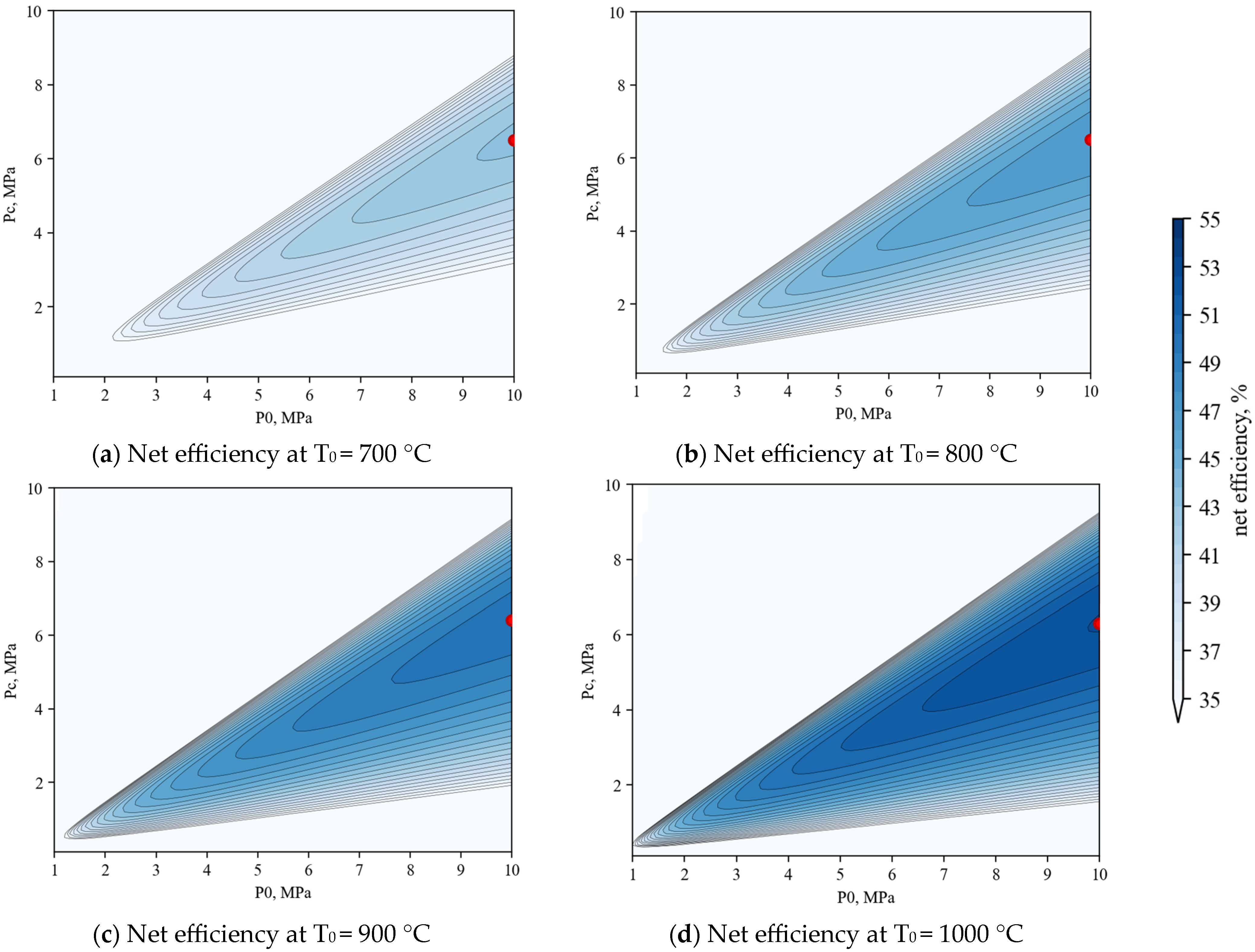
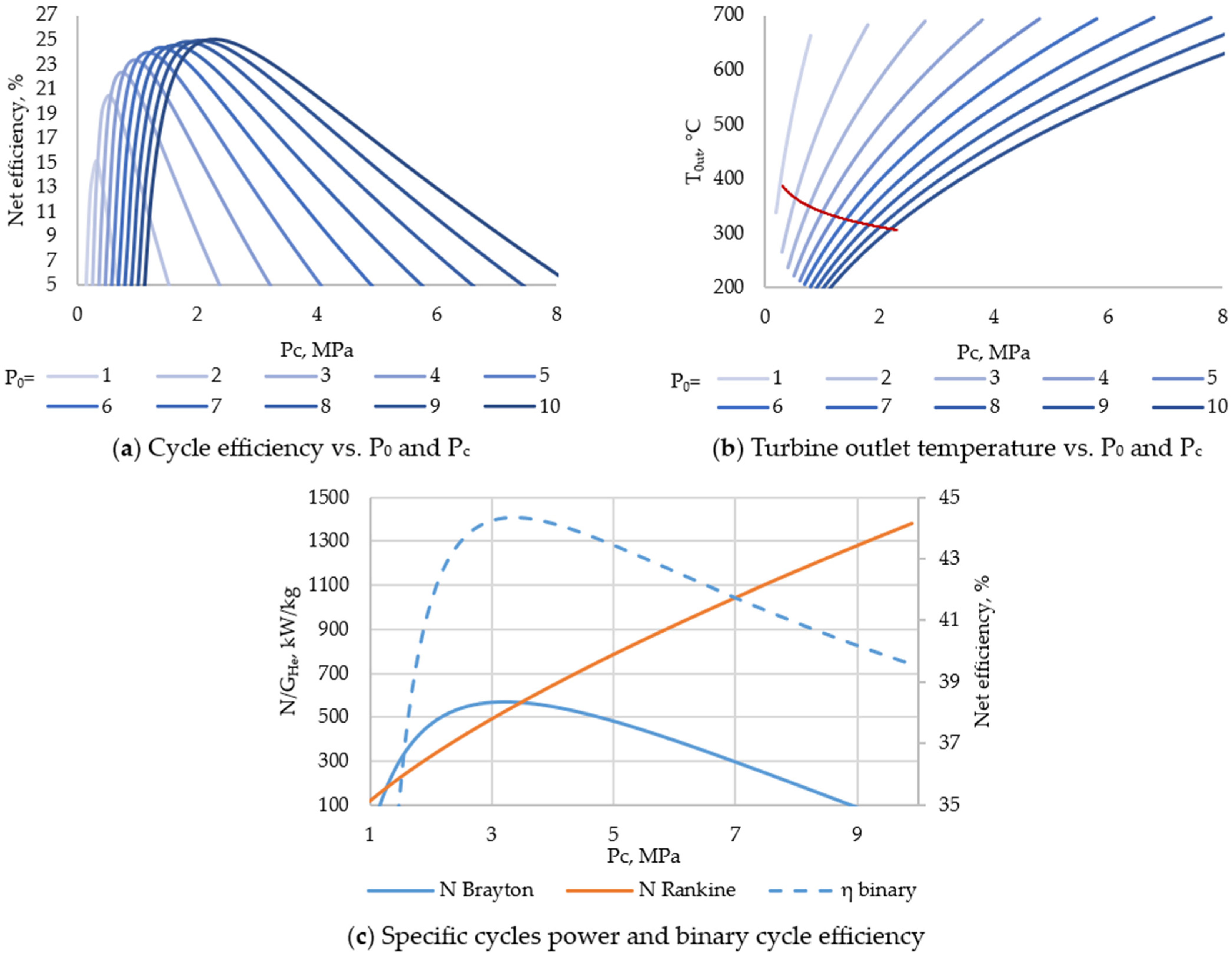
4.3. Helium Cycles for High-Temperature, Gas-Cooled SMRs

In some projects, helium coolants in high-temperature, gas-cooled reactors are used in the direct Brayton cycle for power generation, without an intermediate heat exchanger. The controlling parameters in the cycle design that affect the eventual cycle efficiency are the initial temperature and the pressure ratio in the helium turbo machines. The former parameter is directly dependent on the reactor system design, core configuration, and allowable fuel element parameters, while the latter depends on the design of the compressors and the helium turbine. In existing designs, such a high pressure level is impracticable: generally, the maximum value does not exceed 10 MPa, so the design domain is limited to this value. Figure 13 shows the net cycle efficiency vs. the cycle’s initial and final pressures. With the increase in the cycle’s initial temperature while limiting the maximum cycle pressure to 10 MPa, the maximum efficiency is achieved at a constant pressure ratio of 1.58 (with pressure losses equal to 50 kPa). At these parameters, the net efficiency of the Brayton helium cycle with regeneration makes 40.2%, 44.76%, 48.67%, and 52.05% at initial temperatures of 700 °C, 800 °C, 900 °C, and 1000 °C, respectively.
These results were obtained on the assumption that pressure losses in the cycle heat exchange equipment are equal to 50 kPa; however, this parameter largely depends on the heat exchange equipment design. The calculation results showed that an increase in pressure losses in the heat exchange equipment of the Brayton helium cycle with regeneration of 10 kPa results in a net efficiency loss of 0.5% on average in the considered range (Figure 14).
To increase the efficiency of power generation based on nuclear power units with small helium reactors, a steam turbine cycle can be added. Heat energy is transferred from helium coolant to feedwater through an intermediate heat exchanger–steam generator, which can be installed directly downstream of the reactor system in the helium flow direction or downstream of the helium turbine. The second option allows for the implementation of a binary cycle where a part of the electric power is generated in the helium turbine and the residual heat of the expanded coolant is used to generate electric power in the steam turbine cycle. In this case, an issue to be addressed is the choice of the helium cycle parameters defining, on the one hand, the power generation capacity in it, and, on the other hand, the amount of heat absorbed in the steam cycle.
Figure 15 shows the cycle efficiency and the helium turbine outlet temperature vs. the initial and final cycle pressure. Similarly to the cycle with a recuperator, the simple Brayton cycle has an optimal set of initial P0 and final Pc pressures that provide maximum efficiency. At an initial pressure of 10 MPa and pressure ratio of 4.35, the peak is 25.07% at T0 = 700 °C. This value is much below the cycle efficiency with heat recovery, but the high-temperature turbine exhaust would allow for an eventual efficiency improvement of the simple cycle. Figure 15b shows the dependence of the temperature of the helium expanded in the turbine, which defines the steam turbine cycle power. As the helium turbine exhaust pressure increases, the temperature rises, which allows the steam turbine circuit thermal power to be increased while simultaneously reducing the helium circuit power.
Since the helium cycle-specific power has a maximum at a certain value of the pressure ratio, and the steam turbine cycle power (Figure 15c) increases over the entire range under consideration, there is an optimum pressure ratio value at which the maximum net efficiency of the binary cycle is achieved. Thus, at T0 = 700 °C, this optimum corresponds to the final pressure value Pc = 2.7 MPa and provides an efficiency of 44.35%, which is more than 4% higher than the efficiency of the Brayton cycle with a recuperator.

4.4. Comparative Analysis of Power Cycle Efficiencies for SNPPs

The choice of the most thermodynamically efficient cycle design parameters is important in order to ensure the good technical and economic performance of small nuclear power plants. Depending on the particular type of reactor system operating conditions, the effect of using cycles with unconventional working fluids can be significant. Figure 16 shows a comparison of the net efficiency level of the power cycles considered in this work vs. reactor type and initial temperature.
For PWR-type reactors with initial temperatures up to 350 °C, steam power cycles with dry saturated working fluid are used currently, and the eventual efficiency largely depends on the choice of the cycle design structure and parameters. The claimed efficiency of existing SNPP projects with this reactor type does not exceed 35%, and such a value is achieved with the use of a developed regeneration system. Calculations showed that the efficiency of cycles with an organic coolant does not exceed those of steam power cycles; however, its cycle design is of a simpler structure; therefore, it includes less equipment. The net efficiency of SNPPs with such cycles reaches 30% at 300 °C.
In reactor systems with liquid metal coolants, the use of the cycle design with main steam reheating and intermediate reheating enables a net efficiency value of 42.5% at a steam temperature of 400 °C, 45.7% at 500 °C, and 48.25% at 600 °C. An alternative option is the use of cycles with a carbon dioxide coolant. Based on the calculation results, it was found that at an initial temperature below 550 °C, steam power plants have the highest efficiency; however, at higher parameters, the carbon dioxide recompression cycle efficiency rises and reaches a value of 49.4% at a minimum thermal heat of 5 °C in recuperators, which is more than 1% higher than the steam turbine cycle value. As the initial temperature increases, this difference increases and reaches 3.1% at 700 °C. This indicates that within the high initial temperature region in reactor systems with liquid metal and liquid salt coolants, the use of power cycles with carbon dioxide working fluid could be promising. In this case, in contrast with the steam turbine cycle, the efficiency of the Brayton cycle with recompression depends significantly on the efficiency of the properly sized carbon dioxide heat exchangers. As the minimum temperature difference increases by 5 °C, the net efficiency of such a cycle drops by 0.9% on average.
In high-temperature, gas-cooled reactor systems for power generation, the use of a binary (helium Brayton and steam Rankine) cycle provides a net efficiency of 44.3%, which is 4.1% higher than the efficiency of the helium Brayton cycle with a recuperator at the recuperator thermal head of 20 °C. As the initial temperature increases, however, this difference decreases. As noted above, the recuperator thermal head in gas cycles significantly affects the efficiency, and, in the helium cycle, a 5 °C increase in the temperature difference in the recuperator will result in a net efficiency drop of 1.5%.

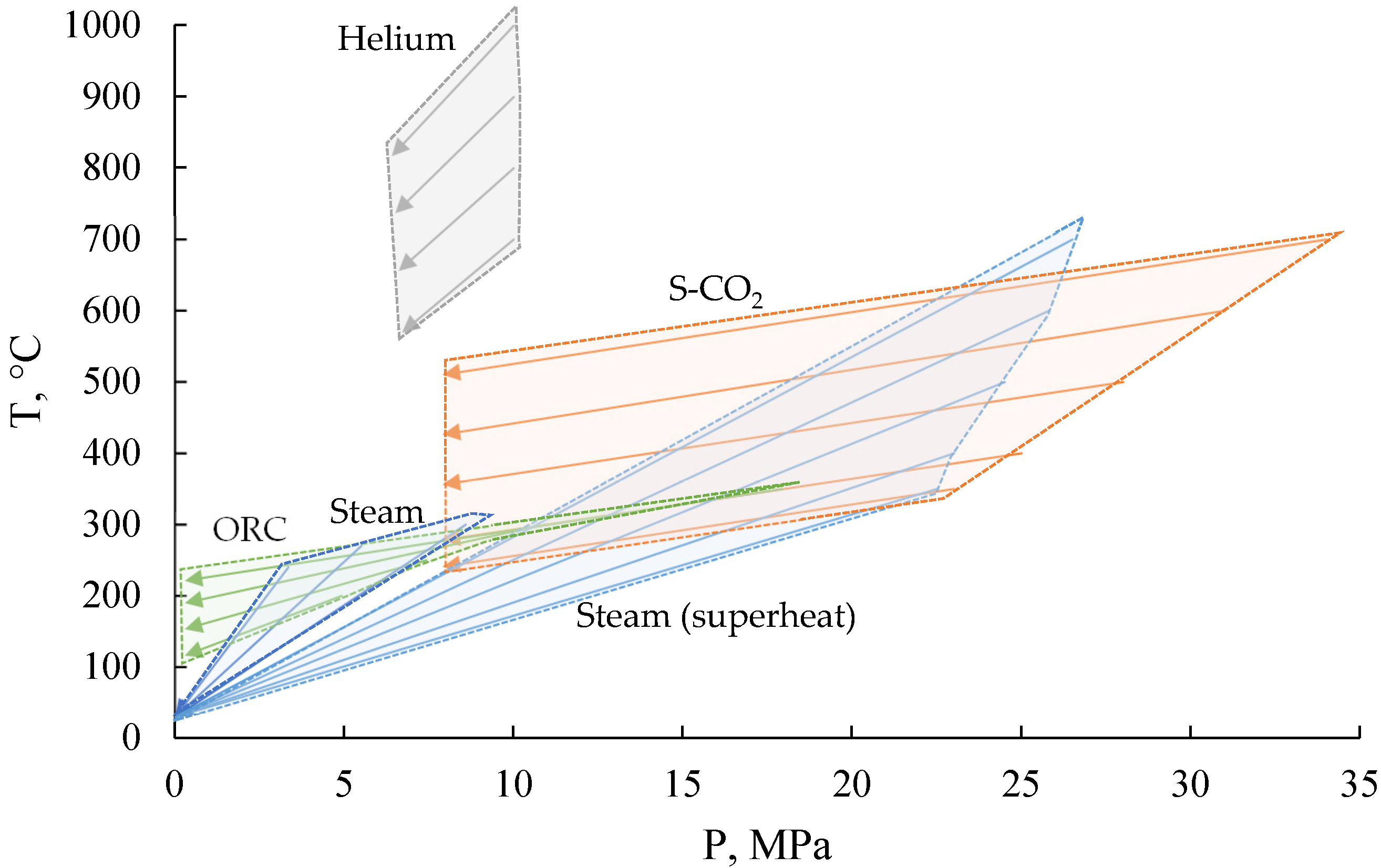
4.5. Comparative Analysis of the Operating Conditions of Power Cycles Equipment for SNPP

Despite the higher level of thermodynamic efficiency of some cycles within the considered temperature range, the eventual choice of power generation design for small nuclear power plants will largely depend on the cost of the power unit. This cost will largely depend on the metal intensity and technical complexity of the manufacturing of the main equipment for the power cycle. In particular, the use of Brayton cycles with a developed regeneration system will require a significant heat exchange area due to low values of convective heat transfer from gas streams; so, the cost of heat exchange equipment for the carbon dioxide and helium cycle will significantly exceed the cost of recuperators for the steam turbine unit. One should also take into account the fact that the use of unconventional equipment (currently, the majority of nuclear power units operate using the Rankine steam turbine cycle) will require significantly higher capital expenditures. In this regard, in order to make the final decision on the choice of power generation technology, not only should thermodynamic efficiency be considered but cost indicators should also be assessed, which is a promising line of work.
In power cycles with unconventional working fluid, the performances of turbo machines and heat exchange equipment differ significantly from the values of steam power cycles. Figure 17 shows the range of performance variation in turbo machines of power cycles with different working fluids. At nuclear power plants using dry saturated steam as a working fluid, steam turbines usually operate at an initial pressure of 6–7 MPa, with subsequent expansion to a pressure below atmospheric pressure corresponding to the saturation pressure at a condenser temperature of 30–40 °C. Therefore, a high degree of fluid expansion will contribute to the need to use a large number of turbine stages, and the low fluid density in the last stages will require the manufacture of long blades. In cycles with freon coolants, the final pressure is higher than the atmospheric pressure, which allows for the use of turbo machines with a small number of stages or even radial-type turbines. One of the advantages of carbon dioxide cycles is the fact that turbo machines operate at high absolute values of initial and final pressures, but the pressure ratio is not high (usually, it does not exceed a value of 2–3), and the design dimensions of carbon dioxide turbines are much smaller than those of steam turbines. The value of pressure drop in helium turbine units is also low, but the operating temperature level is higher (it depends on the HTGR parameters), which raises the requirements for the strength and thermal characteristics of the materials for the main turbine elements manufacture.
Power cycle heat exchange equipment performance also varies significantly, primarily in the heat recovery system units. Conventional NPP steam turbine cycles use a regeneration system consisting of 7–8 condensate and feedwater heaters, where turbine bleed steam heats the water coolant. One of the characteristic features of these heat exchangers is operation with a low pressure difference between hot and cold coolants. This allows the unit design to be simplified and expensive manufacturing materials to be avoided. Another distinctive feature is the fact that heat is transferred at a relatively high heat transfer level, primarily due to the heating steam condensation in the heat exchangers. In the organic Rankine cycle recuperator, the evaporated freon heats the liquid coolant without condensation, which requires a large heat exchange area and ultimately results in a heat exchanger cost rise. This is also facilitated by the fact that the pressure difference between the steam downstream of the turbine and the liquid freon is much higher than that of steam cycles. In carbon dioxide cycles, one of the urgent challenges is the development of efficient heat exchange equipment: the pressure difference between coolants in the HTR and LTR of recompression cycles can reach values of 15–25 MPa, which significantly raises requirements for equipment strength (Figure 18). At the same time, HTRs can operate at rather high temperatures, which additionally affects the strength requirements.
Thus, the use of non-conventional coolants in power cycles of small nuclear power plants can ensure efficient power generation, provided that new design solutions for turbo machines and heat exchange equipment of these cycles are developed.

5. Conclusions

Small modular reactors are a promising direction for the development of power supply systems in regions isolated from unified energy systems. Due to the possibility of a stable, autonomous supply of energy to the consumer without emissions of carbon dioxide into the atmosphere, this technology has recently been actively developed. Increasing the efficiency of electricity production based on such reactors through the use of power cycles with non-traditional working fluids can provide improved technical and economic indicators of projects.
Based on the results of thermodynamic analyses of power cycles for low-power nuclear power plants, the following was found:
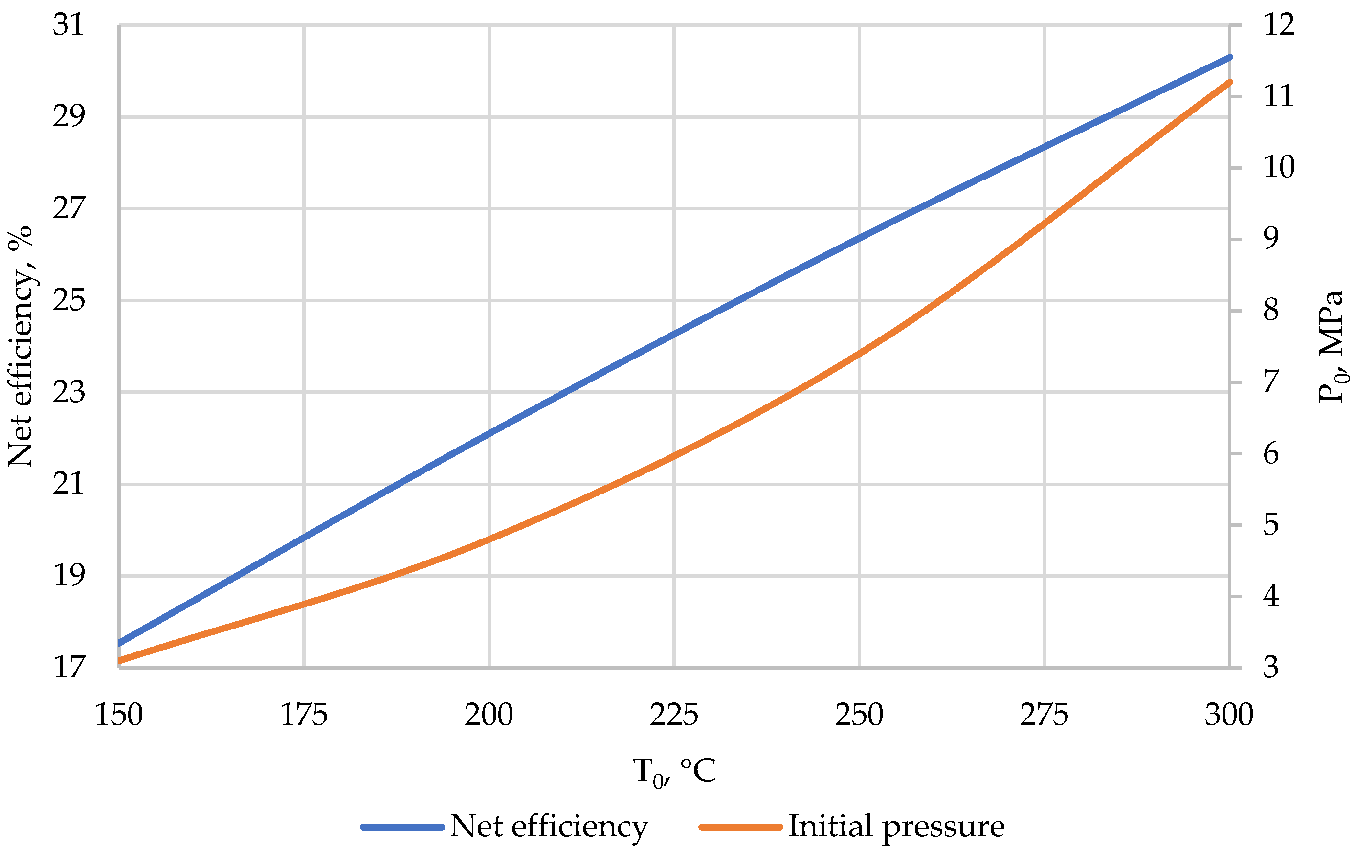
  • For PWR-type reactor plants, in which the coolant temperature does not exceed 350 °C, the highest efficiency of electricity production is achieved when using steam power cycles. Thus, net efficiency at 300 °C can reach 33.5%. The use of cycles using organic coolants provides an efficiency of 30.3%, and, to achieve parameters comparable to the steam power cycle, it is necessary to increase the initial temperature by more than 50 °C. Thus, when using R236ea freon in an organic Rankine cycle with a recuperator, an efficiency of 33.9% is achieved at a temperature of 350 °C.
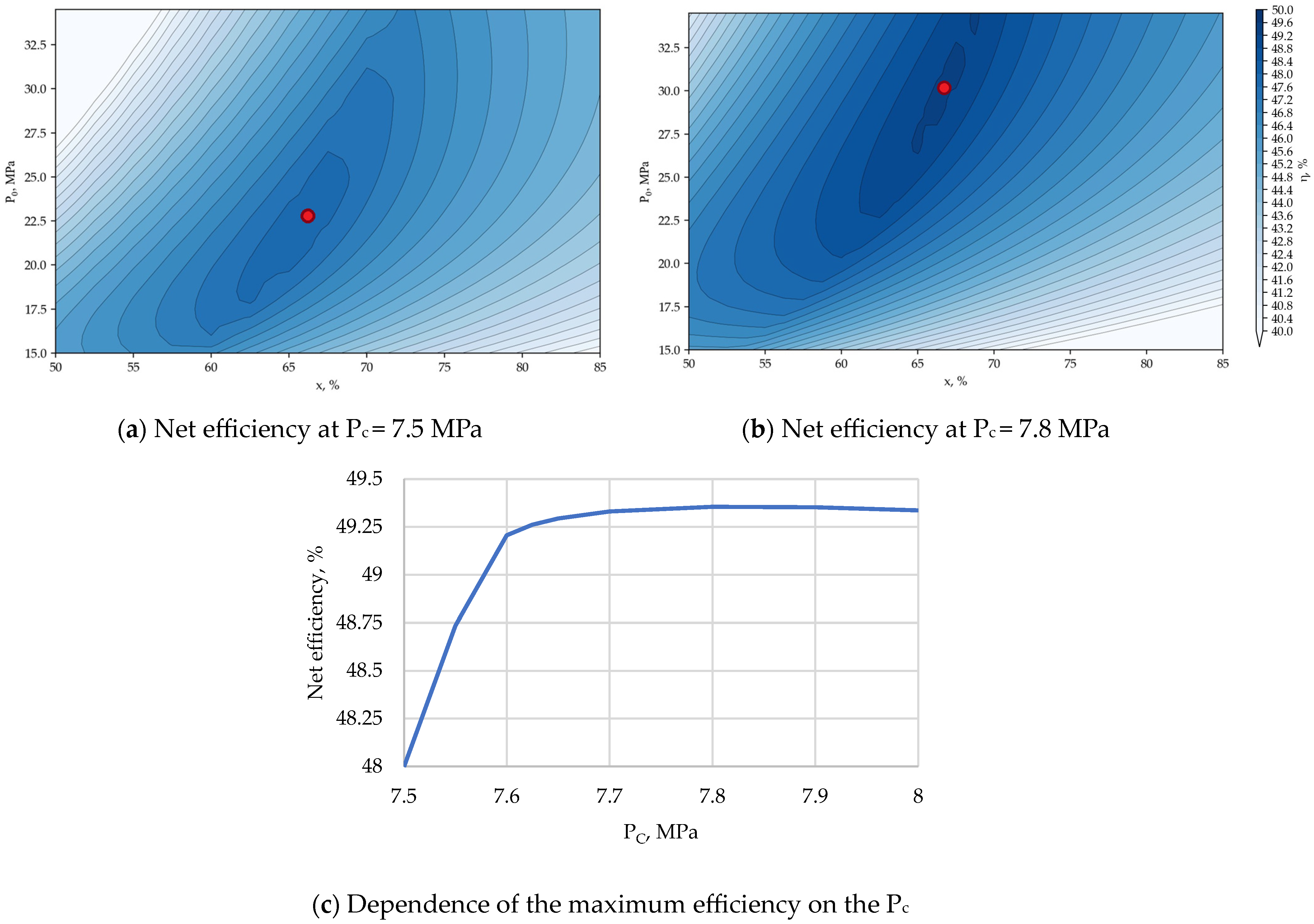
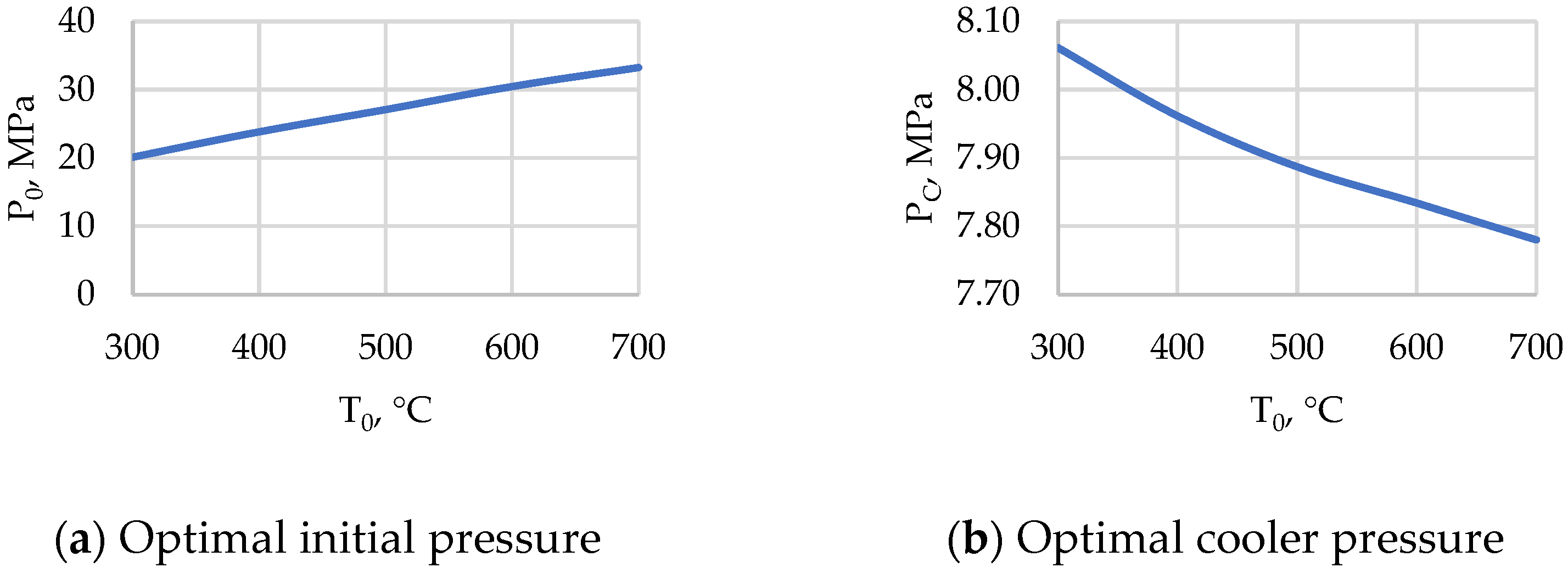
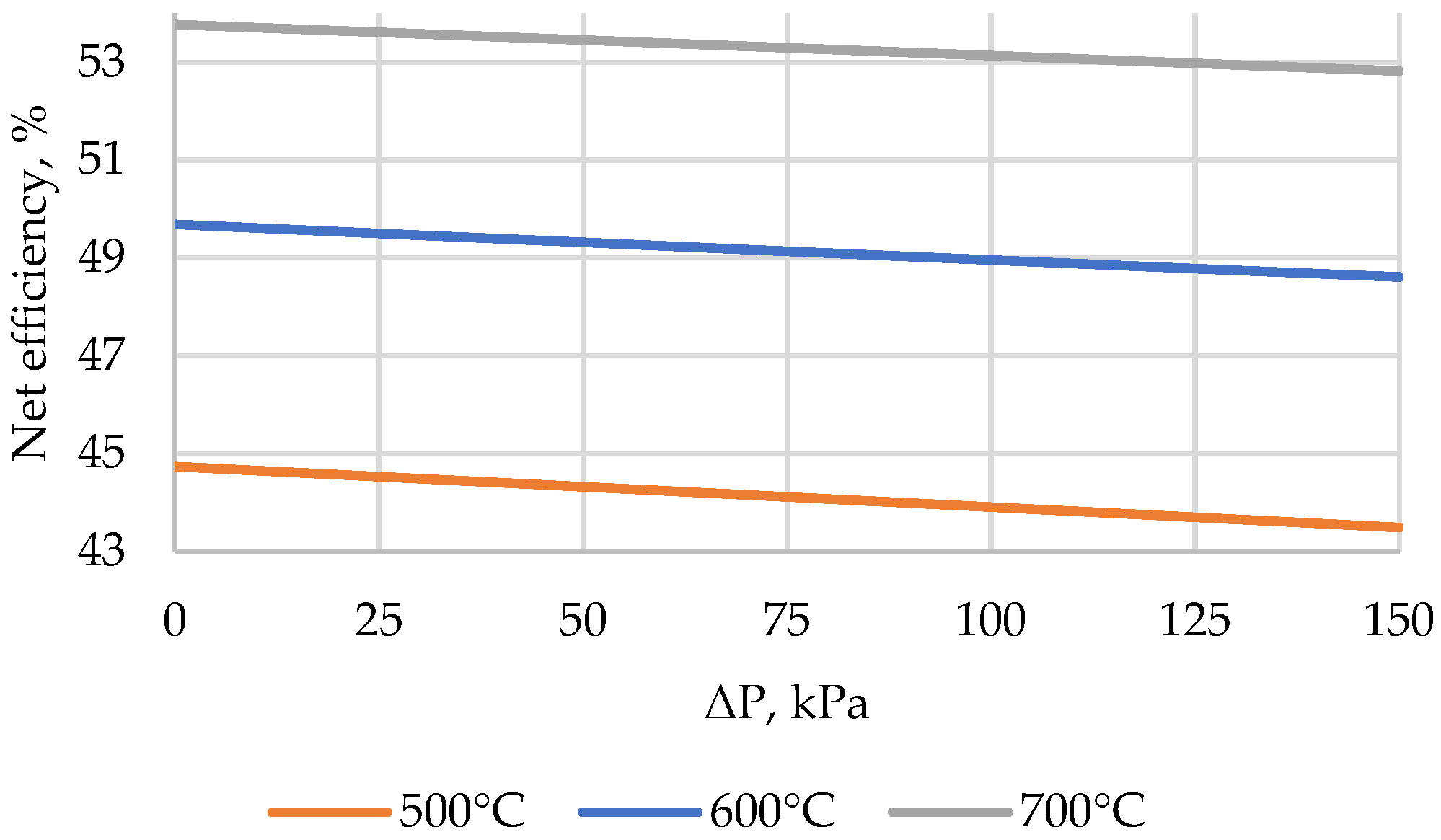
  • For reactor plants with liquid metal and liquid salt coolants in the temperature range up to 550 °C, the highest net efficiency is achieved when using power cycles with a steam–water coolant. The level of initial parameters makes it possible to implement in such a cycle the superheating of live steam in front of the turbine as well as intermediate superheating between the high- and low-pressure cylinders. This ensures the net efficiency of such a cycle at the level of 41.5% at an initial temperature of 400 °C, 45.7% at 500 °C, and 48.2% at 600 °C. In this case, in the temperature range of 550–700 °C, the cycle using a carbon dioxide coolant can have the greatest efficiency. When using the Brayton recompression cycle with CO2, the efficiency of net electricity production reaches values from 46.6% (with a minimum temperature difference in heat exchangers of 20 °C) to 49.4% (with a difference of 5 °C) at 600 °C and 50.7–53.48% at 700 °C. Thus, at an initial temperature above 550 °C, it is promising to use carbon dioxide as a coolant for the power cycle. At the same time, these cycles have a high potential for increasing efficiency due to the utilization of low-temperature heat supplied to the cold source using organic Rankine cycles.
  • For high-temperature, gas-cooled reactor plants, the use of a binary cycle consisting of a helium Brayton cycle and a steam–water Rankine cycle achieves a net efficiency of 44.3% at an initial helium temperature of 700 °C and 52.9% at 1000 °C. This is higher than in the Brayton cycle with a recuperator with a minimum temperature difference in the heat exchanger of 20 °C: the efficiency is 40.2% and 52%, respectively (the efficiency can be increased by reducing the temperature difference, but this will significantly increase the weight and dimensions of the heat exchanger).
  • Despite the thermodynamic efficiency of power cycles using non-traditional coolants, one of the key issues standing in the way of the implementation of such projects is the development of basic equipment (primarily turbomachines and heat exchangers). Thus, helium and carbon dioxide turbines, unlike steam turbines, operate with a lower degree of expansion of the working medium, due to which their dimensions are significantly smaller. In turn, heat exchange equipment operates at a significantly higher pressure difference between coolants (>7 MPa for ORC and >15 MPa for carbon dioxide cycle recuperators), and the requirements for the reliability of the heat recovery system in such cycles increase significantly.
Thus, the use of non-traditional working fluids in power cycles for electricity production may be promising for small modular reactors. However, for the successful commercial implementation of such projects, in addition to high thermodynamic efficiency, it is necessary to ensure a high economic component determined, among other things, by the capital cost of building a power unit.

Author Contributions

Conceptualization, N.R. and A.R.; methodology, V.K.; software, I.M.; validation, A.R.; formal analysis, O.Z.; investigation, I.M.; resources, N.R.; data curation, A.R.; writing—original draft preparation, I.M.; writing—review and editing, N.R.; visualization, O.Z.; supervision, V.K.; project administration, V.K.; funding acquisition, O.Z. All authors have read and agreed to the published version of the manuscript.

Funding

This study, conducted by the National Research University “Moscow Power Engineering Institute”, was supported by the Russian Science Foundation under Agreement No. 23-79-10235.

Data Availability Statement

Data are contained within the article.

Conflicts of Interest

The authors declare no conflicts of interest.

References

  1. Kaundinya, D.P.; Balachandra, P.; Ravindranath, N.H. Grid-Connected versus Stand-Alone Energy Systems for Decentralized Power—A Review of Literature. Renew. Sustain. Energy Rev. 2009, 13, 2041–2050. [Google Scholar] [CrossRef]
  2. Alqahtani, B.J.; Patino-Echeverri, D. Identifying Economic and Clean Strategies to Provide Electricity in Remote Rural Areas: Main-Grid Extension vs. Distributed Electricity Generation. Energies 2023, 16, 958. [Google Scholar] [CrossRef]
  3. Arriaga, M.; Cañizares, C.A.; Kazerani, M. Northern Lights: Access to Electricity in Canada’s Northern and Remote Communi-ties. IEEE Power Energy Mag. 2014, 12, 50–59. [Google Scholar] [CrossRef]
  4. Boute, A. Off-Grid Renewable Energy in Remote Arctic Areas: An Analysis of the Russian Far East. Renew. Sustain. Energy Rev. 2016, 59, 1029–1037. [Google Scholar] [CrossRef]
  5. Rogalev, N.; Rogalev, A.; Kindra, V.; Zlyvko, O.; Osipov, S. An Overview of Small Nuclear Power Plants for Clean Energy Pro-duction: Comparative Analysis of Distributed Generation Technologies and Future Perspectives. Energies 2023, 16, 4899. [Google Scholar] [CrossRef]
  6. Petrunin, V.V. Reactor Units for Small Nuclear Power Plants. Her. Russ. Acad. Sci. 2021, 91, 335–346. [Google Scholar] [CrossRef]
  7. Ingersoll, D.T.; Carelli, M.D. Handbook of Small Modular Nuclear Reactors, 2nd ed.; Woodhead Publishing: Sawston, UK, 2020; ISBN 978-0-12-823917-9. [Google Scholar]
  8. Belyaev, V.M.; Bolshukhin, M.A.; Pakhomov, A.N.; Khizbullin, A.M.; Lepekhin, A.N.; Polunichev, V.I.; Veshnyakov, K.B.; Sokolov, A.N.; Turusov, A.Y. The Worlds First Floating NPP: Origination and Direction of Future Development. At. Energy 2020, 129, 27–34. [Google Scholar] [CrossRef]
  9. Wu, Z.; Lin, D.; Zhong, D. The Design Features of the HTR-10. Nucl. Eng. Des. 2002, 218, 25–32. [Google Scholar] [CrossRef]
  10. China’s Demonstration HTR-PM Enters Commercial Operation: New Nuclear—World Nuclear News. Available online: https://www.world-nuclear-news.org/Articles/Chinese-HTR-PM-Demo-begins-commercial-operation (accessed on 17 January 2024).
  11. Mitsubishi Heavy Industries, Ltd. Global Website|JAEA and MHI Commence Demonstration Program for Hydrogen Production Using a High Temperature Engineering Test Reactor—Project for Achieving Carbon Neutrality. Available online: https://www.mhi.com/news/220427.html (accessed on 5 September 2023).
  12. CAREM-25 (National Atomic Energy Commission Argentina). Passive Safety Systems in Advanced Small Modular Reactors; International Atomic Energy Agency (IAEA): Vienna, Austria, 2014; pp. 190–192. [Google Scholar]
  13. Penn, I.; Plumer, B. Nuclear Energy Project in Idaho Is Canceled. The New York Times 2023.
  14. Advances in Small Modular Reactor Technology Developments. 2022. Available online: https://aris.iaea.org/publications/smr_booklet_2022.pdf (accessed on 20 January 2024).
  15. Dostal, V.; Hejzlar, P.; Driscoll, M.J. The Supercritical Carbon Dioxide Power Cycle: Comparison to Other Advanced Power Cy-cles. Nucl. Technol. 2006, 154, 283–301. [Google Scholar] [CrossRef]
  16. Rogalev, N.; Rogalev, A.; Kindra, V.; Komarov, I.; Zlyvko, O. Structural and Parametric Optimization of S–CO2 Nuclear Power Plants. Entropy 2021, 23, 1079. [Google Scholar] [CrossRef] [PubMed]
  17. Ahn, Y.; Bae, S.J.; Kim, M.; Cho, S.K.; Baik, S.; Lee, J.I.; Cha, J.E. Review of Supercritical CO2 Power Cycle Technology and Current Status of Research and Development. Nucl. Eng. Technol. 2015, 47, 647–661. [Google Scholar] [CrossRef]
  18. Kissick, S.M.; Wang, H. A Comparative Study of Alternative Power Cycles for Small Modular Reactors. Energy Convers. Manag. 2021, 247, 114734. [Google Scholar] [CrossRef]
  19. Dostal, V.; Driscoll, M.J.; Hejzlar, P.; Todreas, N.E. A Supercritical CO2 Gas Turbine Power Cycle for Next-Generation Nuclear Reactors. In Proceedings of the International Conference on Nuclear Engineering, Arlington, VA, USA, 14–18 April 2002; pp. 567–574. [Google Scholar]
  20. Kindra, V.; Rogalev, N.; Rogalev, A.; Naumov, V.; Sabanova, E. Thermodynamic Optimization of Low-Temperature Cycles for the Power Industry. Energies 2022, 15, 2979. [Google Scholar] [CrossRef]
Figure 1. Thermal power and temperature of various existing SMR projects (based on data from [14]).
Energies 17 01650 g001
Figure 2. Schematic diagram of NPP power unit with dry saturated steam turbine unit. (HP/LP ST—high/low-pressure steam turbine, LPH/HPH—low/high-pressure heater, S—separator, SR—steam reheater, D—deaerator, P—pump, C—condenser, G—generator.)
Energies 17 01650 g002
Figure 3. Schematic diagram of nuclear power unit with regenerative Rankine cycle using organic coolant. (P—pump, R—recuperator, C—condenser, G—generator, T—turbine, IHX—intermediate heat exchanger.)
Energies 17 01650 g003
Figure 4. Schematic diagram of NPP power unit with recompression Brayton cycle. (LTR/HTR—low/high-temperature recuperator, MC/RC—main/recompression compressor, C—cooler, IHX—intermediate heat exchanger, T—turbine, G—generator.)
Energies 17 01650 g004
Figure 5. Schematic diagrams of NPPs with high-temperature, gas-cooled reactor. (T—turbine, R—recuperator, C—cooler, MC—main compressor, G—generator, SG—steam generator, ST—steam turbine).
Energies 17 01650 g005
Figure 6. Net efficiency of organic Rankine cycles with regeneration vs. initial temperature, pump pressure, and coolant type.
Energies 17 01650 g006
Figure 7. Plot of optimum pressure and efficiency of organic Rankine cycles with R236ea vs. initial temperature.
Energies 17 01650 g007
Figure 8. T-S diagram of organic Rankine cycles with Freon R236ea for optimum pressure at various initial temperatures. (gray line—saturation line).
Energies 17 01650 g008
Figure 9. Efficiency of SNPPs with reheated steam turbine unit vs. reheating pressure and initial temperature.
Energies 17 01650 g009
Figure 10. Net efficiency of the Brayton recompression cycle at T0 = 600 °C (red points—maximum efficiency).
Energies 17 01650 g010
Figure 11. Optimum parameters and efficiency of S-CO2 cycle with recompression vs. initial temperature.
Energies 17 01650 g011aEnergies 17 01650 g011b
Figure 12. Net efficiency of the Brayton recompression cycle vs. pressure losses in the heat exchanger equipment.
Energies 17 01650 g012
Figure 13. Net efficiency of Brayton helium cycle vs. initial temperature (red points—maximum efficiency).
Energies 17 01650 g013
Figure 14. Dependence of net efficiency of Brayton helium cycle with recuperators on pressure losses in heat exchangers.
Energies 17 01650 g014
Figure 15. Brayton cycle efficiency and turbine outlet helium temperature vs. initial and final pressure at T0 = 700 °C (red line—maximum efficiency).
Energies 17 01650 g015
Figure 16. Efficiency of the considered power cycles vs. temperature and SMR type. (I—PWR, II—LMFR, III—MSR, IV—HTGR).
Energies 17 01650 g016
Figure 17. Range of performance and expansion processes in turbo machines of NPP power cycles with different working fluids.
Energies 17 01650 g017
Figure 18. Range of operating temperatures and pressure differences in heat exchangers of heat recovery system in NPP power cycles using different working fluids.
Energies 17 01650 g018
Table 1. Some projects of small modular reactors at the stage of operation, construction, or final design (based on data from [14]).
ReactorTypeCountryStatusQ, MWN, MWT0, °C
CAREMPWRArgentinaUnder construction10030326
ACP100PWRChinaUnder construction385125319.5
VOYGRPWRUSALicensed (canceled)25077316
KLT-40SPWRRussiaIn operation15035316
RITM-200NPWRRussiaUnder construction17550318
HTR-PMHTGRChinaIn operation250105750
HTR-10HTGRChinaIn operation102.5700
HTTRHTGRJapanIn operation300850
BREST-OD-300LMFRRussiaUnder construction700300535
MARVELLMFRUSAFinal design0.10.027548
Table 2. Main specifications of power cycle equipment.
ParameterValue
Minimum temperature difference in heat exchangers5 °C
Heat losses in heat exchangers1%
Mechanical, electric generator, and electric drive efficiencies99%
Isentropic efficiency of turbo machines and compressors90%
Isentropic efficiency of pumps85%
Minimum steam dryness factor at turbine outlet90%
Pressure loss at the gas side of heat exchangers50 kPa
Temperature at the cold source of the cycle30 °C
(32 °C for S-CO2)
Table 3. Parameters of research objects.
TypeCoolantTemperature RangePower Cycles
PWRWaterup to 350 °CORC
Steam Rankine (without superheat)
LMFRLiquid metals (Na/Pb)500–650 °CSteam Rankine (with superheat)
S-CO2 recomp.
MSRMolten salts650–800 °CSteam Rankine (with superheat)
S-CO2 recomp.
HTGRHelium700–1000 °CHelium Brayton
Helium–steam binary cycle
Disclaimer/Publisher’s Note: The statements, opinions and data contained in all publications are solely those of the individual author(s) and contributor(s) and not of MDPI and/or the editor(s). MDPI and/or the editor(s) disclaim responsibility for any injury to people or property resulting from any ideas, methods, instructions or products referred to in the content.

