1. Introduction
In last decades, zinc oxide (ZnO) has been extensively investigated for its potential as a semiconductor material in various applications such as biosensing [
1], gas sensing [
2,
3], photovoltaics [
4,
5], and photocatalysis due to its high electron mobility and thermal conductivity, significant binding exciton energy, and wide band gap energy of 3.37 eV at room temperature. Interestingly, ZnO photoanodes have recently emerged as an attractive alternative to titanium dioxide (TiO
2)-based ones in the field of DSSCs owing to their similar band gap energy, advantageous crystallization and electrical conduction capabilities, and significantly higher electron mobility, i.e., from 110 to 150 cm
2/V·s vs. 10
−5 cm
2/V·s [
6,
7].
The morphology and surface area of nanostructured materials, such as ZnO and TiO
2, play a crucial role in their performance and effectiveness in various applications [
8,
9]. Previous reports have highlighted the need for improvements in ZnO-based devices due to their low performance, with conversion efficiencies ranging from about 0.4 to 5.8% [
10]. The synthesis routes significantly impact the morphological properties and associated applications of ZnO, particularly at the nanoscale level where unique properties are observed compared to bulk materials. Researchers have previously described various ZnO nanostructures such as nanoflower-like [
7], nanorods [
11], nanotubes [
12], nanowires [
13], nanoplates [
14], nanobelts [
15], tetrapod [
16], and nanoparticles [
17]. In addition to sol-gel and hydrothermal methods, the precipitation method is advantageous given its ease of control and repeatability while allowing adjustment of particle size through temperature modulation and capping agents. Moreover, calcination procedure and temperature also influence ZnO nanoparticles production.
The importance of nanostructure morphology and surface area in the context of ZnO materials lies in their direct impact on the performance and effectiveness of various optoelectronic applications [
18]. The morphology refers to the shape and structure of the nanostructures, while surface area relates to the amount of exposed material available for interaction. Nanostructures with different morphologies, such as nanorods, nanowires, and nanoparticles, have unique properties that can enhance their performance in applications such as DSSCs [
19]. For example, nanostructures with a high surface area-to-volume ratio can provide more reactive sites for efficient charge transfer and light absorption. In addition, the nanostructure morphology can affect the electron transport and recombination processes within the material, which ultimately impact device efficiency.
The field of photovoltaics has witnessed a paradigm shift with the advent of DSSCs, noted for their lower production costs and potential for high-energy conversion efficiency, rivaling traditional silicon-based counterpart. Central in the DSSC architecture is the photoanode, which traditionally employs titanium dioxide (TiO
2) nanoparticles due to their favorable band gap energy and chemical stability. Yet, the search for improved photoanode materials that could overcome the inherent limitations of TiO
2, particularly regarding electron transport, has been robust and unrelenting. Zinc oxide has emerged as a particularly promising alternative, possessing similar band gap energy to TiO
2, yet offering superior electron mobility, which is crucial for enhancing overall cell efficiency [
20,
21]. ZnO’s unique physicochemical properties can be attributed to its nanostructured forms, which provide an extensive surface area for dye loading and a versatile framework for electron transport—two crucial parameters that directly affect the efficiency of DSSCs. It has been observed that a reduction in particle size leads to an increase in the specific surface area, thus offering more active sites for dye absorption and enabling a more effective light-harvesting mechanism. Consequently, nanostructures such as nanoparticles, nanowires, and nanorods have been extensively studied to optimize these interactions [
22,
23].
As the scientific community delves deeper into the nanoscale, it becomes evident that not only the size but also the morphology of ZnO nanostructures critically influences their optoelectronic properties. The intricacies of electron pathway selection, light scattering, and recombination rates are inherently tied to the structural form factor. For example, one-dimensional ZnO structures, with their longitudinally aligned pathways, can offer a more direct route for electrons transfer, thereby limiting opportunities for electron–hole recombination. Conversely, multi-dimensional structures, such as ZnO microballs, avail themselves not only as efficient light scatterers but also as potential contributors to improved charge collection due to their unique geometries [
14,
24]. Recognizing this, our research examines a range of ZnO nanostructures, tailored through careful synthesis to alter their size and morphology systematically. By evaluating their performance as photoanodes in DSSCs, our aim is to elucidate the impact of nanostructure morphology on device efficiency.
2. Materials and Methods
2.1. Synthesis of ZnO Nanoparticles
The synthesis of ZnO nanoparticles in a colloidal solution in ethanol was carried out following an in-house-developed method [
25,
26]. In more detail, ethanolic solution of 4 mM zinc acetate and 4 mM NaOH solution were prepared under rigorous stirring at 50 °C. A volume of 20 mL of zinc acetate solution was then complexed with 20 mL of pure ethanol followed by heat treatment at 70 °C for 30 min. A volume of 20 mL of the NaOH solution was then added and the mixture solution was finally hydrolyzed for 2 h at 60 °C. The schematic representation of the synthesis process of ZnO nanostructures is presented in
Figure 1a.
2.2. Synthesis of ZnO Microballs
The ZnO microballs were synthesized in aqueous media by reducing a mixture of zinc acetate dihydrate and monosodium citrate using sodium hydroxide. The samples were hydrolyzed at 120 °C in an autoclave for different time duration. The microballs were of different shapes and sizes depending upon the concentration of zinc acetate and sodium citrate and the annealing time. The powders were thoroughly washed with deionized (DI) water and ethanol. The concentrations of the reactants used were the following: zinc acetate dihydrate 62.5 mM, monosodium citrate 87.5 mM, sodium hydroxide 2 M. The growth continued for 8 h, and at the end the sample was thoroughly washed with DI water and ethanol and dried at 100 °C.
2.3. Synthesis of ZnO Spiky Microballs
The synthesis procedure was exactly the same as ZnO microballs except that the pH was maintained at 6 during the growth process.
2.4. Synthesis of ZnO Triangles
The triangle-like structure was prepared by heat-treating an aqueous solution of 0.2 M zinc nitrate and hexamine at a temperature of 95 °C for 8 h. The sample was then centrifuged, and the residue thoroughly washed with DI water and annealed at 250 °C for 1 h to remove all organic deposits. pH was maintained at 8.
2.5. Synthesis of ZnO Belts
The procedure was the same as for the ZnO triangles. The formation of the belts took place when the pH of the growth solution was maintained at 12.
2.6. Fabrication of Dye-Sensitized Solar Cells (DSSCs)
2.6.1. Preparation of Photo-Electrode
A number of 3 cm × 3 cm fluorine-doped tin oxide (FTO)-coated glass slides purchased from Asahi Glass, Tokyo, Japan (12 Ω/sq) were used as the substrate for the fabrication of DSSC photo-electrode. The FTO glass substrates were initially cleaned in an ultrasonic bath with soap water, ethanol, acetone and finally DI water for 20 min per process and then dried in an oven at 90 °C for 1 h. Subsequently, the different hydrothermally grown ZnO nanostructured materials were coated on the cleaned FTO glass substrate through the doctor-blade technique, followed by calcination at 350 °C for 1 h in a muffle oven.
2.6.2. Dye Adsorption, Preparation of Counter Electrode and Assembly of Solar Cells
The dye adsorption onto the photo-electrode as well as the preparation of the counter electrode were carried out following the procedures already standardized in the NanoLab at the Asian Institute of Technology (AIT). In more detail, a 0.5 mM solution of N719 (cis-bis (isothiocyanato)bis(2,2′-bipyridyl-4,4′-dicarboxylato)-ruthenium (II)bis- tetrabutyl ammonium) dye was prepared by adding 0.11877 g of the N719 dye powder purchased from Solaronix S.A. (Aubonne, Switzerland) in 200 mL ethanol. The mixture was continuously stirred for about 12 h to obtain a homogeneous solution. The FTO substrates with the semiconducting layer were then dipped in the dye solution for 24 h in the dark for the adsorption of dye molecules. The substrates were first heated at 100 °C for 30 min before immersing them into the dye solution to get rid of any moisture present in the semiconducting layer. After 24 h, the photo-electrode was taken out from the dye solution and rinsed with ethanol to remove unadsorbed dye molecules from the surface of the photo-electrode. The photo-electrodes were then allowed to dry at room temperature before assembling the DSSC, whose structure is schematized in
Figure 1b.
To prepare the counter electrode, two small holes were drilled into another FTO coated glass of same dimension as the photo-electrode (3 cm × 3 cm) to allow the injection of the liquid electrolyte. The latter consisted of 0.5 M lithium iodide (LiI), 0.05 M iodine (I
2) and 0.5 M 4-tert-butylpyridine (TBP) in acetonitrile (ACN). A thin layer of platinum (Pt) nanoparticles was deposited on the counter electrode to increase the rate of reduction of the electrolyte at the counter electrode/electrolyte interface. The counter electrode before and after Pt deposition is shown in
Figure 1c. Two layers of surlyn
® 1702 (purchased from Dupont, Wilmington, DE, USA) were placed in between the two electrodes as spacer and sealant with the gap between the two electrodes maintained at 70 μm. The DSSC was then sealed by applying heat and pressure simultaneously using the DSSC assembly machine developed at the NanoLab at AIT. A temperature of 95 °C and a pressure of 2.6 kg/m
2 were used to melt the surlyn for sealing the DSSC. A complete DSSC is shown in
Figure 1d.
2.7. Morphological Analysis
Field emission scanning electron microscopy (FESEM) images of the ZnO nanostructures were obtained using a JSM-6301F (JEOL Ltd., Tokyo, Japan) operated at 15 kV. Transmission electron microscopy (TEM) was carried out by applying a drop of the ZnO samples of different morphology to carbon-coated copper grids. Particle sizes were determined from micrographs recorded at various magnifications using an FEI (Tecnai S-Twin, Hillsboro, OR, USA) operating at 200 kV.
3. Results
ZnO nanoparticles, microballs, microballs with spikes (spiky microballs), belts and triangles were used as photo-electrode material to fabricate DSSCs. Thin films of these materials with thickness of ~1 µm were prepared by using doctor-blade technique, and the corresponding SEM images are shown in
Figure 2.
3.1. SEM Morphology
Figure 2 depicts the typical features one would expect to observe in SEM images for various ZnO morphologies, such as nanoparticles, microballs, spiky microballs, plates and triangles.
SEM images of ZnO nanoparticles typically display a homogenous collection of discrete, fine particles with distinctive morphology. These nanoparticles generally show a well-distributed size range, often between 10 and 50 nm. Their relatively uniform and small size can lead to a high surface-to-volume ratio, advantageous for efficient dye adsorption in DSSCs. ZnO microballs appear as larger spherical structures in SEM images, with diameters ranging from 1 to 4 µm. They often present a smooth or slightly textured surface. The microballs may exhibit features indicating polycrystallinity, and their enlarged size compared to nanoparticles results in a different balance between surface area and light scattering properties in DSSC applications. In SEM, spiky ZnO microballs are distinguished by their unique morphology exhibiting radial protrusions or spike-like features emanating from a central spherical core. These distinctive structures significantly expand the overall surface area, which can potentially enhance dye loading and light-trapping capabilities, thereby improving the efficiency of DSSCs. The SEM images of ZnO plates would reveal flat, two-dimensional structures with sharp edges. These nanostructures display a distinctly different morphology compared to spherical forms and are often laid out in an overlapping order due to their large, flat structure. The low-resolution images of ZnO nanotriangles show a bunch of nanotriangles that it does not provide any distinct features, but the red highlighted areas clearly show the triangular features.
3.2. TEM Morphology
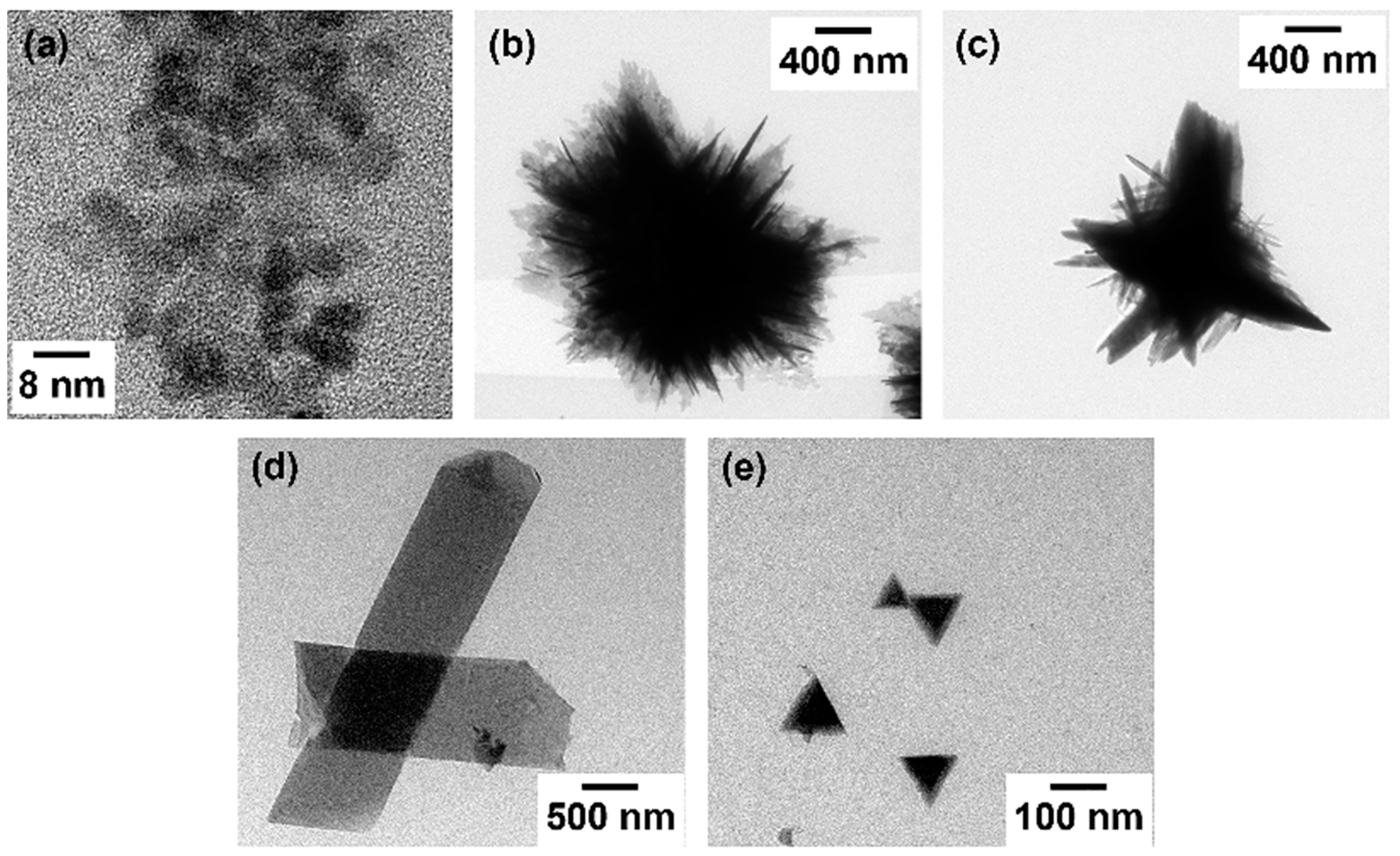
The high-resolution TEM micrographs of the different ZnO morphologies object of this study are reported in
Figure 3. TEM images of ZnO nanoparticles typically show uniform, spherical or quasi-spherical shapes. Owing to their small size, which is usually in the range of 1–1.2 µm for microballs, spiky microballs and belts and of 5–100 nm for nanoparticles and nanotriangles, the particles often exhibit a high degree of crystallinity with clear lattice fringes. The uniform size and shape are indicative of controlled synthesis conditions leading to well-defined and monodisperse nanoparticles. ZnO microballs, which are larger in size compared to standard nanoparticles, appear as larger, uniform spheres a few micrometers in diameter. In TEM images, these microballs might exhibit either a solid core or a porous structure, depending on the controlled chemical synthesis method. The surface of the microballs looks relatively smooth with small protrusions, and the bigger particles also show clear lattice fringes indicative of crystallinity. In contrast to regular microballs, spiky ZnO microballs appear as spheres with protruding needle-like structures. These spikes significantly increase the surface area. This morphology is often the result of a secondary growth process where anisotropic growth leads to the formation of these protruding structures on the spherical surface. TEM images of ZnO plates reveal flat, elongated or rectangular features, which are identifiable by their thin, plate-like morphology. They can occasionally show as overlapping plates if the sample preparation stacks these nanostructures. The high aspect ratio of the plates is typically associated with preferential crystal growth along the c-axis of the wurtzite ZnO structure. In the TEM, ZnO triangles look as triangular shapes, often with sharp edges and corners. These nanostructures provide a high aspect ratio and increased edge sites, which are beneficial for applications like DSSCs where they can facilitate enhanced electron transport and provide more active sites for dye adsorption.
The morphology of nanostructures plays a crucial role in enhancing the performance of various solar cell technologies and in particular of DSSCs. More specifically, the use of ZnO nanostructures with diverse morphologies, such as nanoparticles or nanorods, can result in different surface areas and electron transport properties [
27]. This variation in surface area can affect the performance of DSSCs by influencing the adsorption of dye molecules and facilitating efficient charge transfer. In addition, the morphology of nanostructures can also impact the light absorption properties of the material [
28]. For example, nanostructured ZnO films with a higher surface area may have a greater capacity to absorb light, leading to enhanced energy conversion efficiency in DSSCs [
27].
3.3. Diffraction Pattern of ZnO Nanostructures
Figure 4 depicts the diffraction patterns of all the ZnO nanostructures studied in this work.
ZnO nanoparticles exhibit diffraction patterns that are dense with concentric rings, highlighting their high symmetry and polycrystalline nature. Since nanoparticles can be randomly oriented relative to the incident X-ray or electron beam, the resulting rings match the various planes of the hexagonal wurtzite structure of ZnO. The broadening of these rings or spots may also indicate smaller crystal sizes according to the Scherrer equation. For ZnO microballs, the diffraction pattern is often characterized by well-defined spots or rings, signifying crystalline order within a larger particle size compared to the nanoparticles. While the foundational wurtzite structure of ZnO remains intact, fewer orientations are present due to the size and potential self-assembly of the microballs. Hence, spots may be sharper, and distinct peak widths are discernible. The diffraction patterns from spiky ZnO microballs might resemble that of standard microballs but with additional complexity arising from the spikes. There might be more pronounced diffraction spots corresponding to the directions of the spikes, which may represent elongated crystal growth along specific planes, with prominent orientation along the c-axis due to the anisotropic growth. ZnO plates will produce diffraction patterns wherein certain planes are emphasized significantly—most notably, planes parallel to the plate surfaces.
All the above-discussed diffraction patterns reveal distinct peaks corresponding to the crystal planes of ZnO, such as (100), (002), and (101).
The nanoparticles offer a large surface area due to their small size, which enhances dye adsorption. The dye molecules attach to the ZnO surface, facilitating efficient light absorption. Additionally, the small dimensions of nanoparticles minimize charge recombination; in other words, electrons generated by light absorption can move freely through the nanoparticle network, reducing losses. ZnO microballs are spherical structures composed of ZnO nanoparticles. Their diffraction pattern exhibits characteristic rings due to the radial arrangement of crystal planes; these rings correspond to the (101) and (002) planes. Microballs scatter light effectively due to their spherical shape, and in turn enhanced light scattering increases the path length for light absorption [
29]. When light enters the DSSC, it interacts with the dye molecules and ZnO microballs, increasing the probability of absorption. The spherical geometry also reduces electron recombination, improving charge collection; i.e., electrons generated by dye excitation can efficiently move toward the electrode. However, a larger microball size may limit dye adsorption. Spiky microballs have protruding spikes on their surface, resulting from preferential growth along specific crystallographic directions. Their diffraction pattern combines ring-like features with sharp peaks corresponding to the spikes. These spikes enhance the surface area, allowing more dye molecules to adsorb. The unique morphology balances light scattering (similar to microballs) and increased surface area (due to spikes). Spiky microballs offer improved dye adsorption and efficient charge separation. The spikes create additional pathways for electrons, reducing recombination losses; overall, spiky microballs contribute to enhanced DSSC performance. ZnO belts resemble elongated structures, akin to belts or ribbons, and show symmetrical rings with high crystallinity. Their diffraction pattern reveals elongated peaks along specific crystallographic directions; these belts consist of multiple ZnO nanoplates stacked together, forming a continuous structure. The unique geometry provides extended pathways for electrons transport within the DSSC [
30,
31]. Belts enhance light absorption due to their extended surface area, and electrons can move efficiently along the elongated structure, minimizing recombination. Proper alignment and orientation of belts are crucial for optimal DSSC efficiency. The diffraction patterns observed in ZnO nanotriangles exhibit a striking similarity to those of spiky microballs, which can be attributed to their sharp and pointed edges. This resemblance suggests that both materials share comparable characteristics, likely influencing their solar cell properties. In the context of DSSCs, both ZnO nanotriangles and spiky microballs demonstrate similar open-circuit voltage (
Voc) and short-circuit current density (
Jsc). However, the fill factor (FF) is notably lower in the DSSC incorporating spiky microballs, which may be due to the non-uniformity present on the film’s surface, potentially affecting the cell’s overall efficiency.
3.4. Application of ZnO Thin Films as the Photo-Electrode of DSSCs
DSSCs with an active area of 4 mm
2 were then fabricated and their
I-V characteristics were measured using a solar simulator (model 96000, Newport Corporation, Irvine, CA, USA) at 100 mW/cm
2 (1 sun AM1.5) and 25 °C, with a source measure unit (2400 Keithley, Solon, OH, USA). The
J-V curves for the fabricated ZnO-based DSSCs using photo-electrodes synthesized with different morphologies and N719 dye as the sensitizer are shown in
Figure 5, while the main photovoltaic parameters are summarized in
Table 1.
It is well-known that the morphology and its distribution have a strong influence on photovoltaic performance. From these results, it can be concluded that the ZnO nanotriangles DSSC exhibited the highest efficiency of 2.62% compared to all the other ZnO nanostructures. The lowest photocurrent of 1.23 mA/cm2 was observed in the case of the ZnO microballs DSSC due to the small cracks present in the prepared thin film. In the case of the ZnO spiky microballs, a higher photocurrent was observed (Jsc = 7.57 mA/cm2) when compared with the ZnO nanoparticles DSSC (Jsc = 6.46 mA/cm2), which is due to the increase in the total surface area of the photo-electrode due to the spikes. Conversely, a lower FF was observed in the case of both ZnO microballs (~48%) and spiky microballs (~39%) DSSC compared with the ZnO nanoparticles DSSCs (~60%) due to the electrolyte leaking through the small cracks present in the thin films during cell preparation.
As displayed in
Table 1, the FF of these DSSCs was mostly greater than 45%, which may be due to the relatively low series resistance in the cell, as evident from the properties of the counter-electrode used in this work. The measured open-circuit voltage (
Voc) and short-circuit photocurrent density (
Jsc) were revealed to be 0.58 V and 6.46 mA/cm
2 for ZnO nanoparticles DSSC; 0.52 V and 1.23 mA/cm
2 for ZnO microballs DSSC; 0.61 V and 7.57 mA/cm
2 for ZnO spiky microballs DSSC; 0.56 V and 4.42 mA/cm
2 for ZnO belts DSSC; and 0.62 V and 7.88 mA/cm
2 for ZnO triangles DSSC. The ZnO spiky microballs and triangles DSSCs exhibited the highest
Voc and
Jsc values and showed a photo-conversion efficiency of 1.79 and 2.62%, respectively. Interestingly, the ZnO triangles DSSC achieved an improved efficiency compared to the value of 2.11% reported by Chang et al. [
32]. On the other hand, ZnO nanoparticles DSSC showed an efficiency of 2.22% with an increased FF of 59.38%, which is comparable to the FF of ZnO triangles DSSC.
4. Discussion
The variation in pH levels influences the formation of ZnO nanostructures through its impact on the kinetics and thermodynamics of ZnO crystal growth.
4.1. Microballs
At modestly high pH levels, ZnO precursors in solution have enough hydroxide ions to facilitate the formation of ZnO crystals. Growth is isotropic, and particles can aggregate to form spherical shapes. The higher pH induces a slower nucleation process, allowing for more controlled growth and the possibility of spherical “microball” formation due to the symmetrical addition of material on all sides of the growing particles.
4.2. Spiky Microballs
Spiky microballs form under unique conditions where moderately high pH encourages the formation of microballs, followed by an anisotropic growth phase where specific crystal facets grow faster. This discrepancy in growth rates can cause spikes to protrude from the surface of the microballs, likely due to the preferential attachment of ZnO units along certain crystallographic directions, such as the c-axis, under specific pH conditions.
4.3. Belts
ZnO belts are often formed under alkaline conditions where the growth along certain crystallographic planes is favored over others. The belts’ elongated shape might be the result of a controlled growth process where the pH encourages the expansion of ZnO crystals primarily in one direction, creating a belt-like morphology.
4.4. Triangles
The formation of triangular ZnO structures is typically observed at higher pH levels. Elevated pH can lead to a higher concentration of OH− ions, which can selectively stabilize certain crystal facets over others, especially non-polar facets over polar facets. Because ZnO has a hexagonal wurtzite structure, which has different types of surfaces with varying stability, the high pH conditions can lead to a morphology that reflects the internal crystalline symmetry—in this case, triangular.
These pH-induced differences in crystal growth are the result of a solution’s ionic product, which governs the ZnO nucleation and growth process. The nucleation rate, facet stability, and crystallite size are all influenced by the ionic concentrations, which are themselves dependent on the pH. Moreover, the presence of different ions or molecules (such as capping agents) in the synthesis solution can further influence how the pH affects the growth of various ZnO nanostructures. Such agents may selectively adhere to certain crystal facets, affecting growth rates and leading to the development of diverse morphologies.
4.5. Effect of ZnO Mophology on DSSC Performance
One of the synthesized photoanodes outperformed the standard ZnO nanoparticles-based photo-electrode, as
Figure 5 and
Table 1 show. ZnO displays a similar band gap and band position to TiO
2, but it is characterized by a higher electron mobility, lower combination rate, and better crystallization into various nanostructures than TiO
2 [
31]. Many studies have focused on preparing ZnO with high efficiency in electron transport and photon capturing [
33]. However, ZnO-based DSSCs still exhibit relatively low overall conversion efficiencies compared to TiO
2-based systems. This could be explained by the instability of ZnO in acidic dye and the slow electrons-injection kinetics from dye to ZnO. It was noticed that the semiconductor films started to dissolve into the dye solution when they were soaked for a long time. This is because the sensitizer produces protons that make the dye solution slightly acidic, which causes the dissolution of the ZnO colloid [
5]. This low local pH at the ZnO surface during dye sensitization results in the loss of Zn
2+ ions from the ZnO surface. The dye forms complexes with Zn
2+ ions, which fill the pores of the semiconductor films. It is assumed that only dye molecules directly attached to the ZnO surface can inject electrons effectively and contribute to the photocurrent [
34,
35].
The performance of DSSCs depends on several factors, such as the light absorption, electrons injection, and charge recombination of the dye-sensitized metal oxide semiconductor layer. In this study, the photoelectric conversion efficiency of DSSCs using various ZnO nanostructures as a photoanode was compared. ZnO-based cells were found to exhibit lower efficiency than the TiO
2 counterpart, despite showing enhanced dye loading. This can be explained by the different electrons’ dynamics of the two semiconductors. ZnO tends to form complexes with some dyes, which reduces the electron injection efficiency and increases the charge recombination rate. TiO
2, on the other hand, displays better electron transport and a longer electron lifetime, which results in a higher open-circuit voltage and photocurrent. These findings are consistent with previous studies [
19,
36] that reported similar trends for TiO
2- and ZnO-based DSSCs.
5. Conclusions
The main objective of this study was to explore the effect of different ZnO nanostructures on the performance of DSSCs. ZnO morphologies with various shapes and sizes, such as nanoparticles, microballs, spiky microballs, belts, and triangles, were synthesized and used as a transport layer in DSSCs. The current–voltage characteristics of the DSSCs were measured and their power conversion efficiencies compared. The triangular ZnO nanostructures, which exhibited the smallest size and the sharpest edges, allowed achieving the highest efficiency of 2.62%, followed by the spherical nanoparticles with an efficiency of 2.22%. The microball and spiky microball ZnO nanostructures showed much lower efficiencies of 0.31 and 1.79%, respectively, due to the presence of micro-cracks in the thin film. The triangular ZnO nanostructures also exhibited the highest fill factor of 59.88%, indicating a better match between the transport layer and the electrolyte. Our results demonstrate that the morphology of ZnO nanostructures plays a crucial role in determining the performance of DSSCs, and that smaller and sharper nanoparticles can enhance the charge transport and collection efficiency in DSSCs.


