Design and Experimental Tests of a Four-Way Valve with the Determination of Flow Characteristics for Building Central Heating Installations Using Solid Modeling
Abstract
:1. Introduction
- Precise control of the flow of the refrigerant introduced into the system, which allows for adaptation to the current environment and operating conditions of the cooling/heating system;
- Reduction of greenhouse gas emissions through the increased efficiency that results from the minimization of the amount of flow of the factor required at a given moment;
- Durability of the system, of which the four-way valve is a part. Lower consumption resulting from optimal refrigerant flow results in reduced use of the cooling/heating system devices.
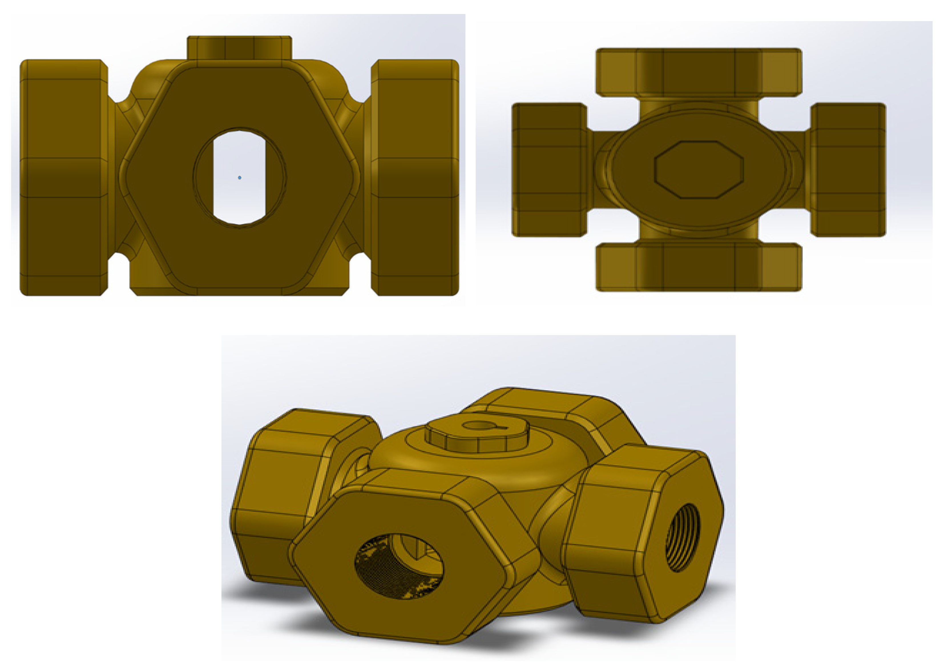
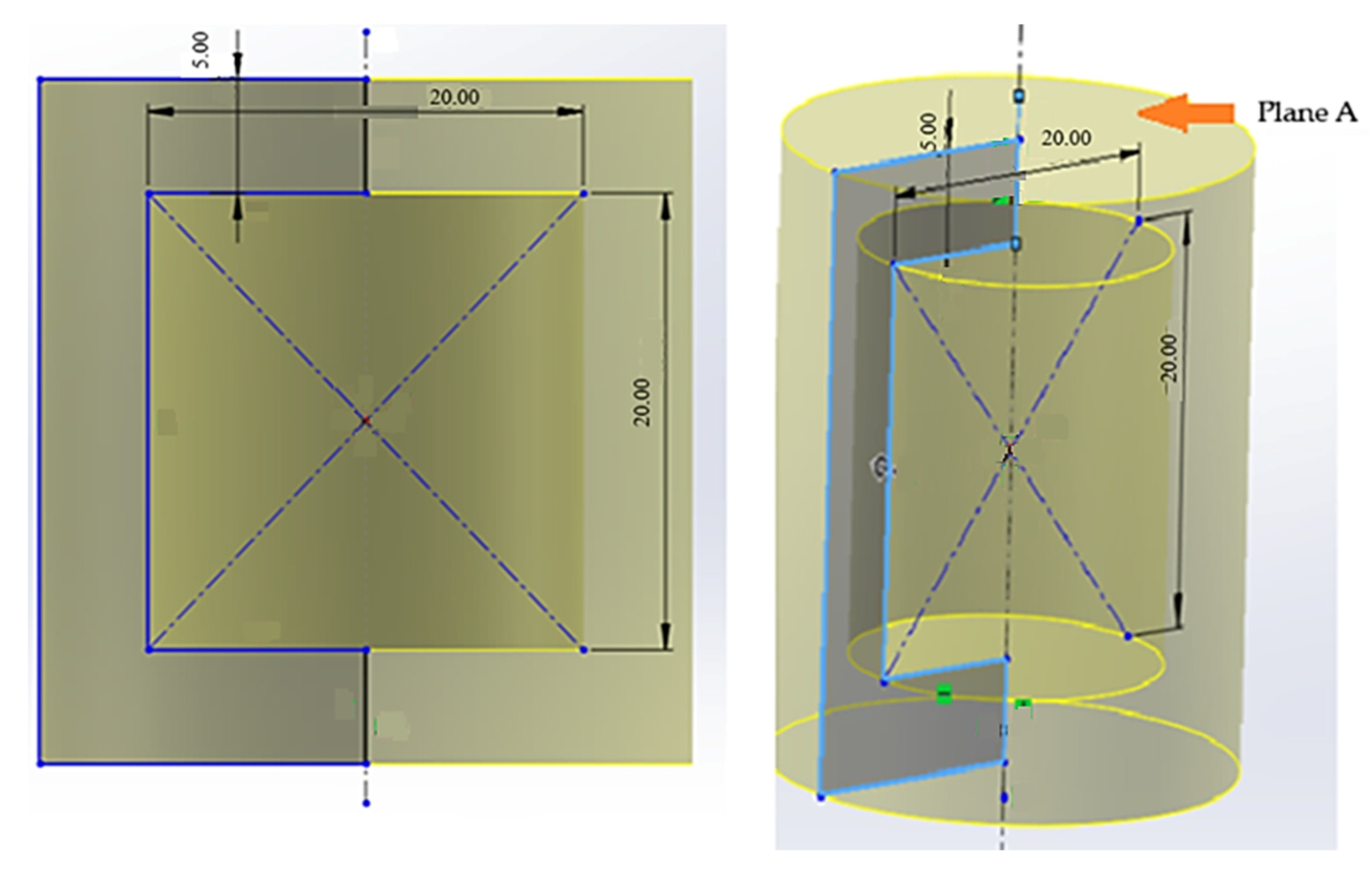
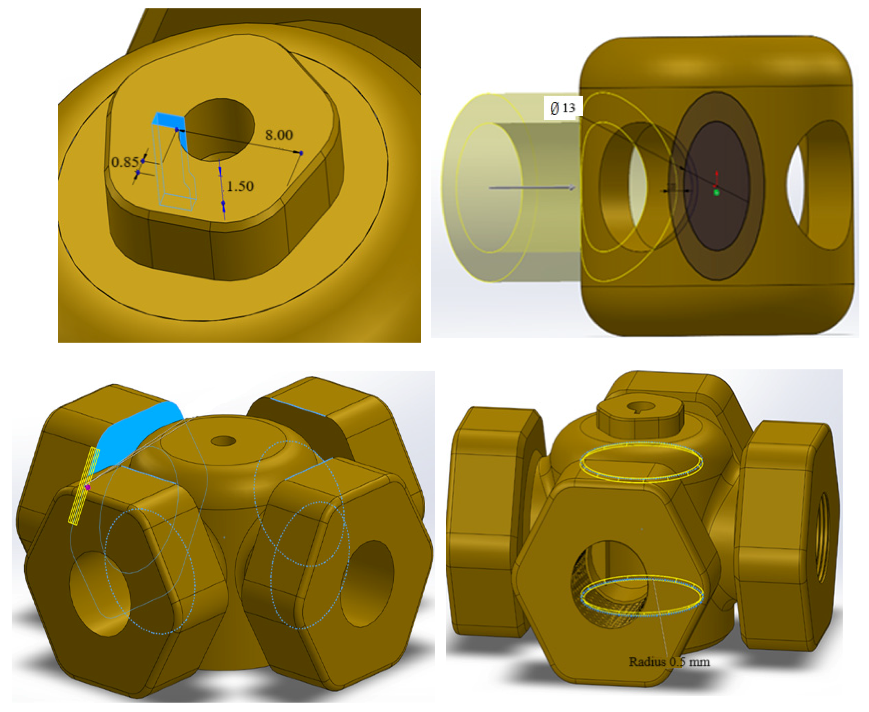
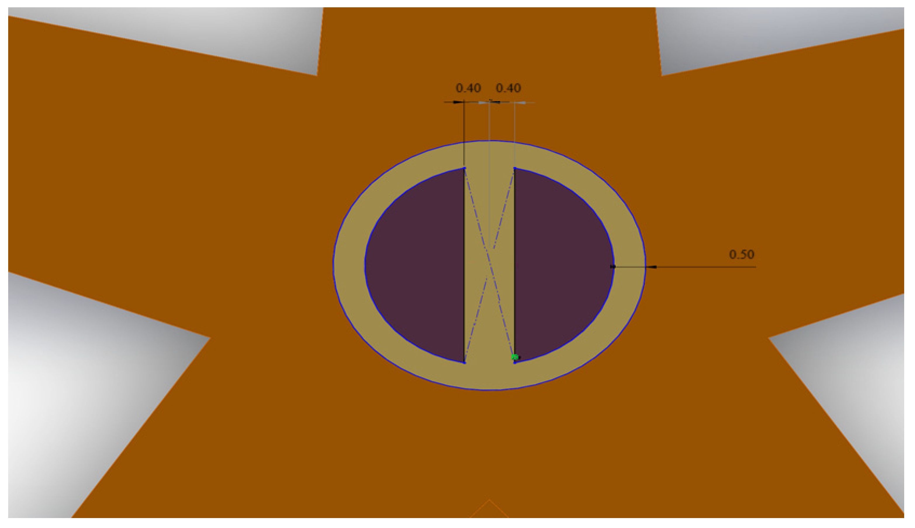
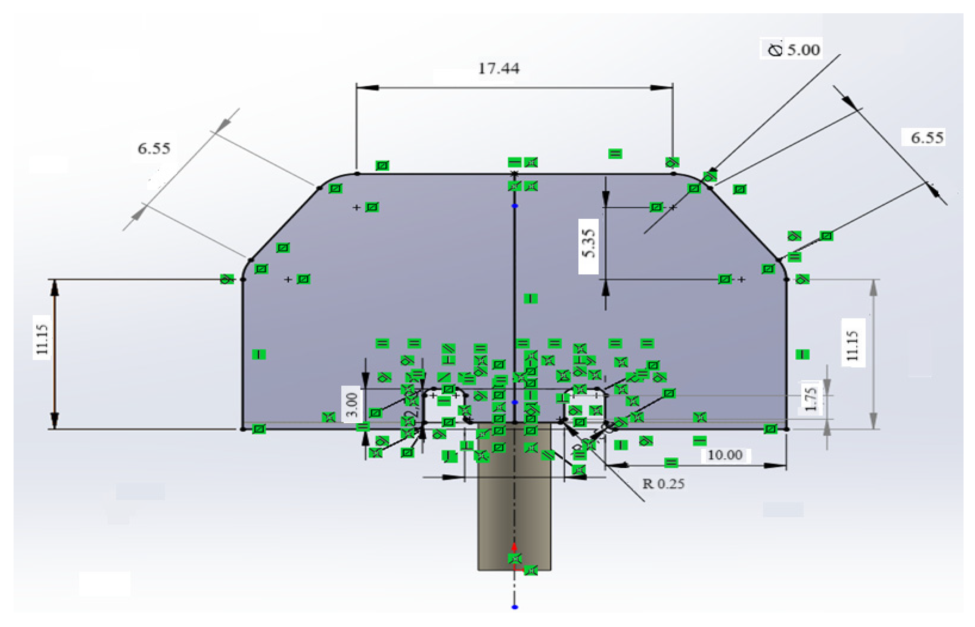
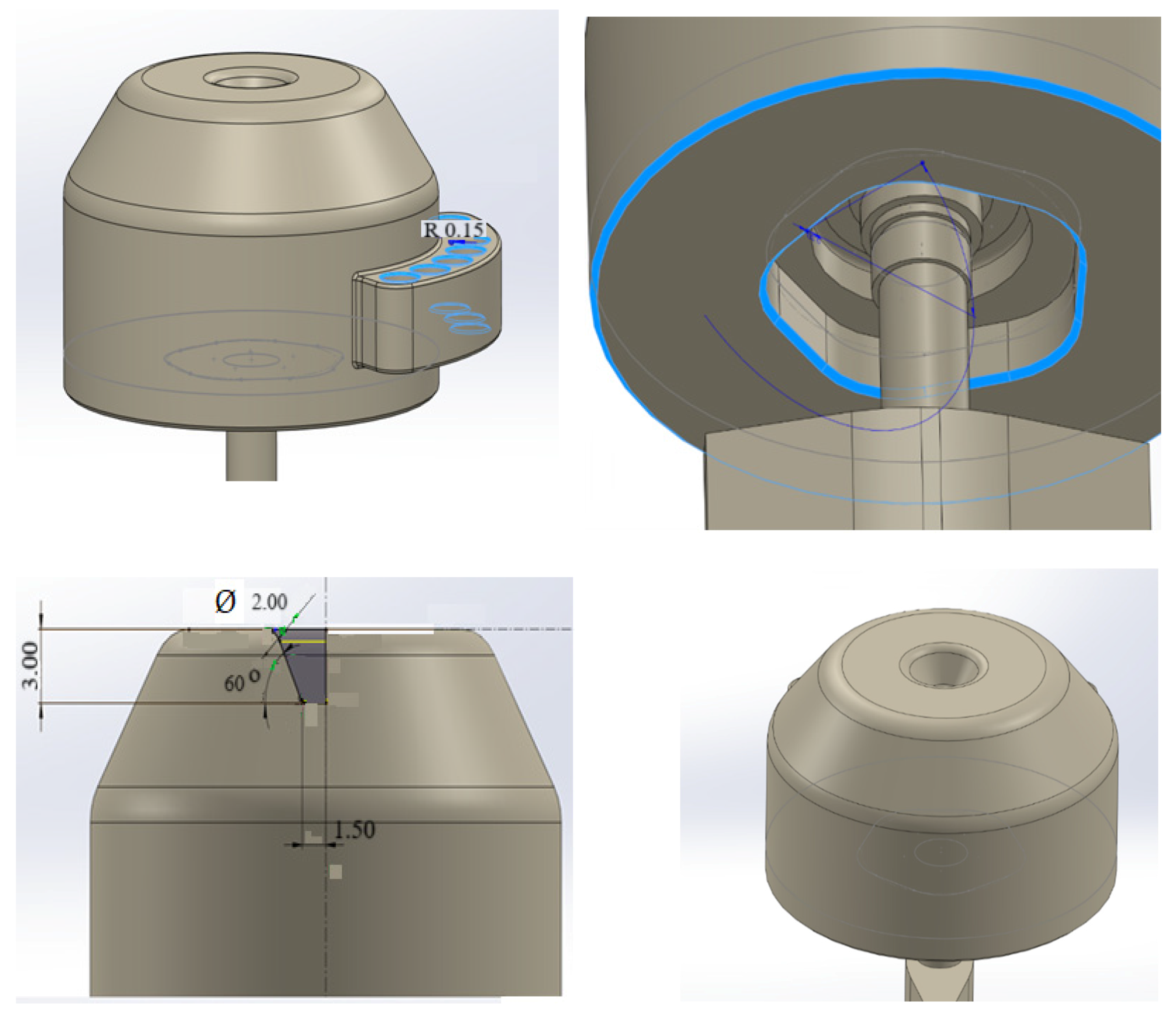
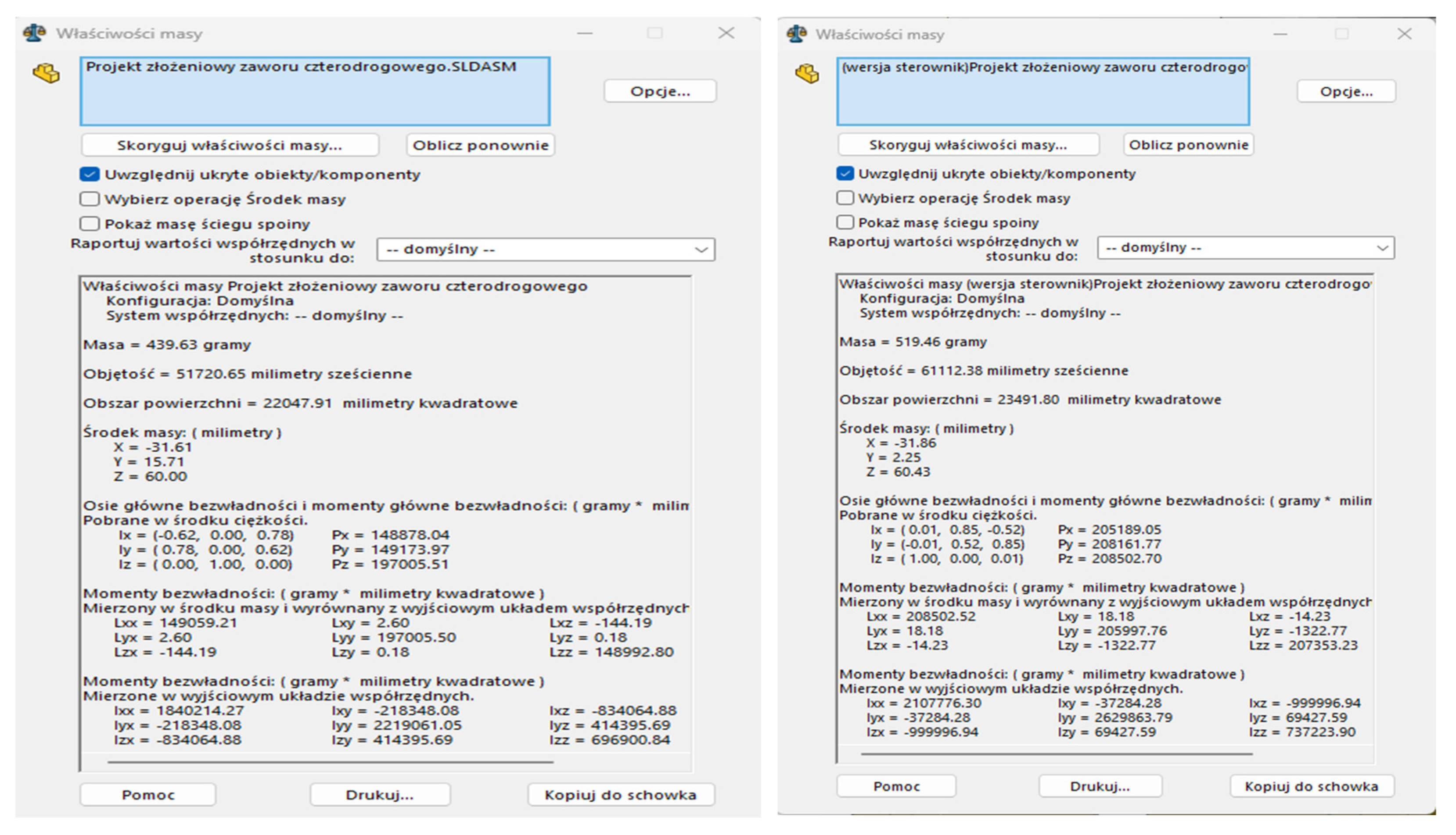
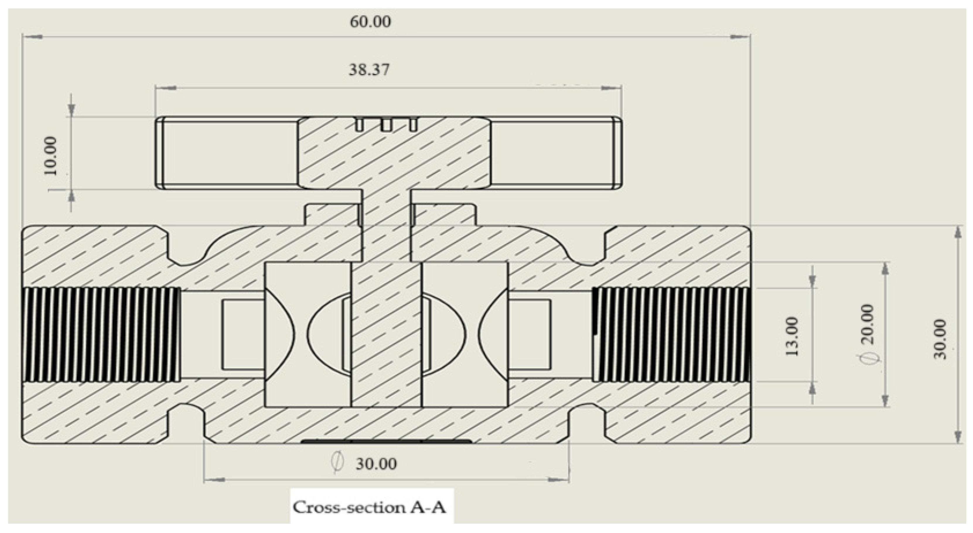
- Assembly design of a four-way valve in SolidWorks software. The goal here is detailed technical documentation of the created assembly geometry, including isometric projections, dimensions, operations used, types of threading (parameters), units used, relationships between sketch elements of each stage of solid creation, and instructions for the activities performed in the SolidWorks software in the form of photographs. The entire project is made of two separately created parts: a four-way valve body and a replaceable lever.
- Examination of potential failures of individual elements of the four-way valve using failure mode and effects analysis.
- Strength tests in SolidWorks software using static analysis.
- An analysis of refrigerant optimization in terms of environmental impact.
2. Literature Review
- Ports and flows: A four-way valve has four ports or inputs/outputs, which are often called “A”, “B”, “AB”, and “OB”. “A” and “B” are connection ports for two substance streams (e.g., cooling liquid and return liquid in the heating system). “AB” and “OB” are the mixing and splitting ports.
- Mixing and separating: The main function of the valve is to regulate the flow of substances through the “AB” and “OB” ports. If the valve is set to “mix,” the substances flowing through ports “A” and “B” are mixed in the proportions specified by the valve setting. When set to “split”, substances flowing through port “AB” are distributed to ports “A” and “B” depending on the ratio set by the valve.
- Setting the proportion: The four-way valve has a mechanism that allows one to adjust the flow proportion between the ports. This allows one to adjust the temperature or other system parameters as needed. This is often accomplished through a rotation lever or crank on the valve.
- Temperature control: In heating and cooling systems, a four-way valve can control the temperature of the liquid circulating in the installation. By changing the proportions between hot and cold liquid, the desired temperature in the circuit can be achieved.
- Automation: In advanced systems, four-way valves can be controlled automatically by building management systems or controllers. This allows the system to dynamically adjust flow proportions in response to changing external or internal conditions.
- Valve body:This is the main element of the entire structure, constituting most of its volume. The body has channels with holes through which the media introduced into the system flows. This part of the structure is made of corrosion-resistant metal, the most commonly used are stainless steel and aluminum.
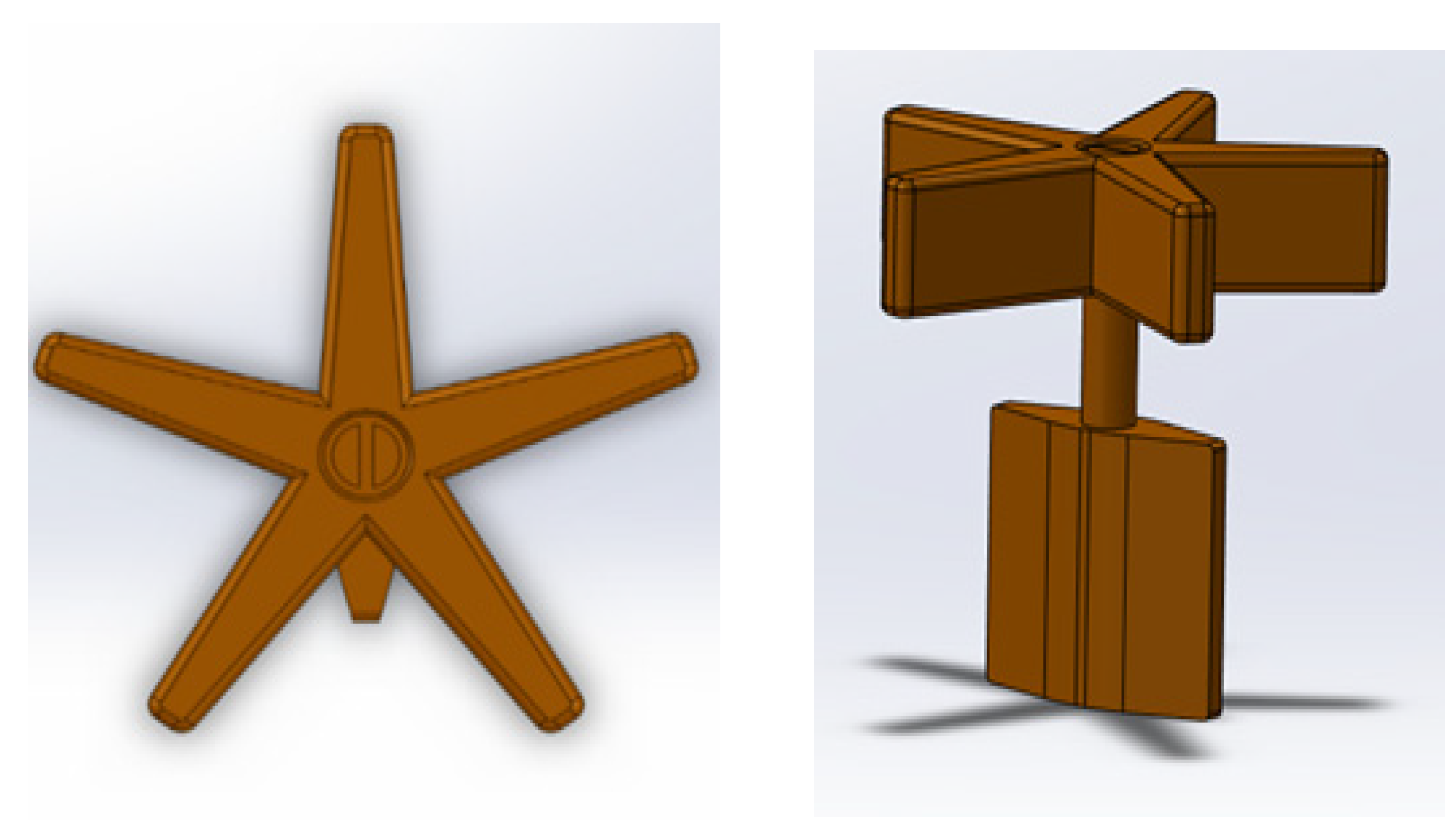
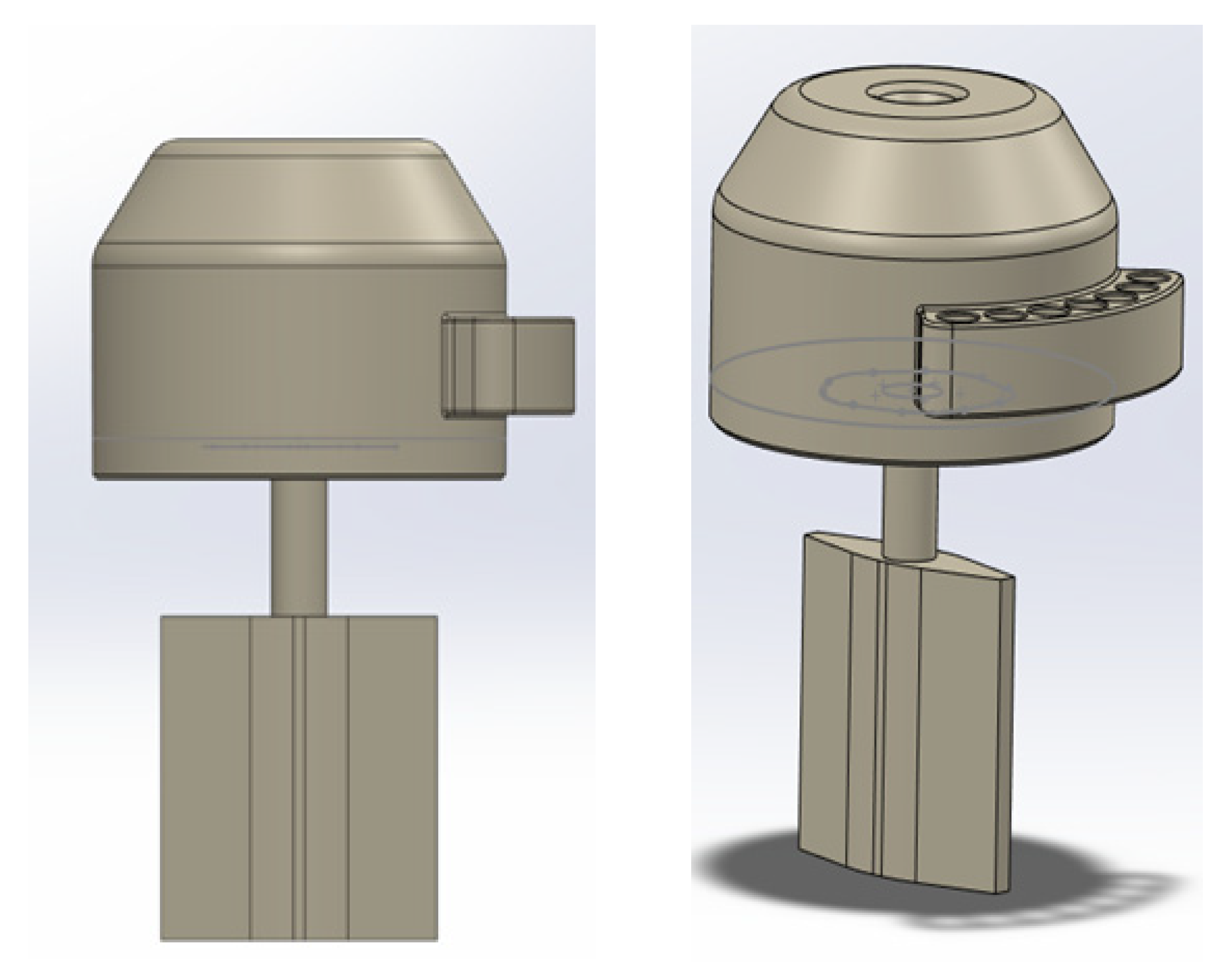
- Container:This is the movable part of the valve, which allows the medium to flow in a controlled manner thanks to two plugged channels that enable the mixing of the medium and its flow in the selected direction.
- Sealing kit:This is a set of all of the elements that seal the valve structure. They are located at the junction of the moving elements with the valve body, blocking uncontrolled leakage of the medium outside the system in which the four-way valve is located.
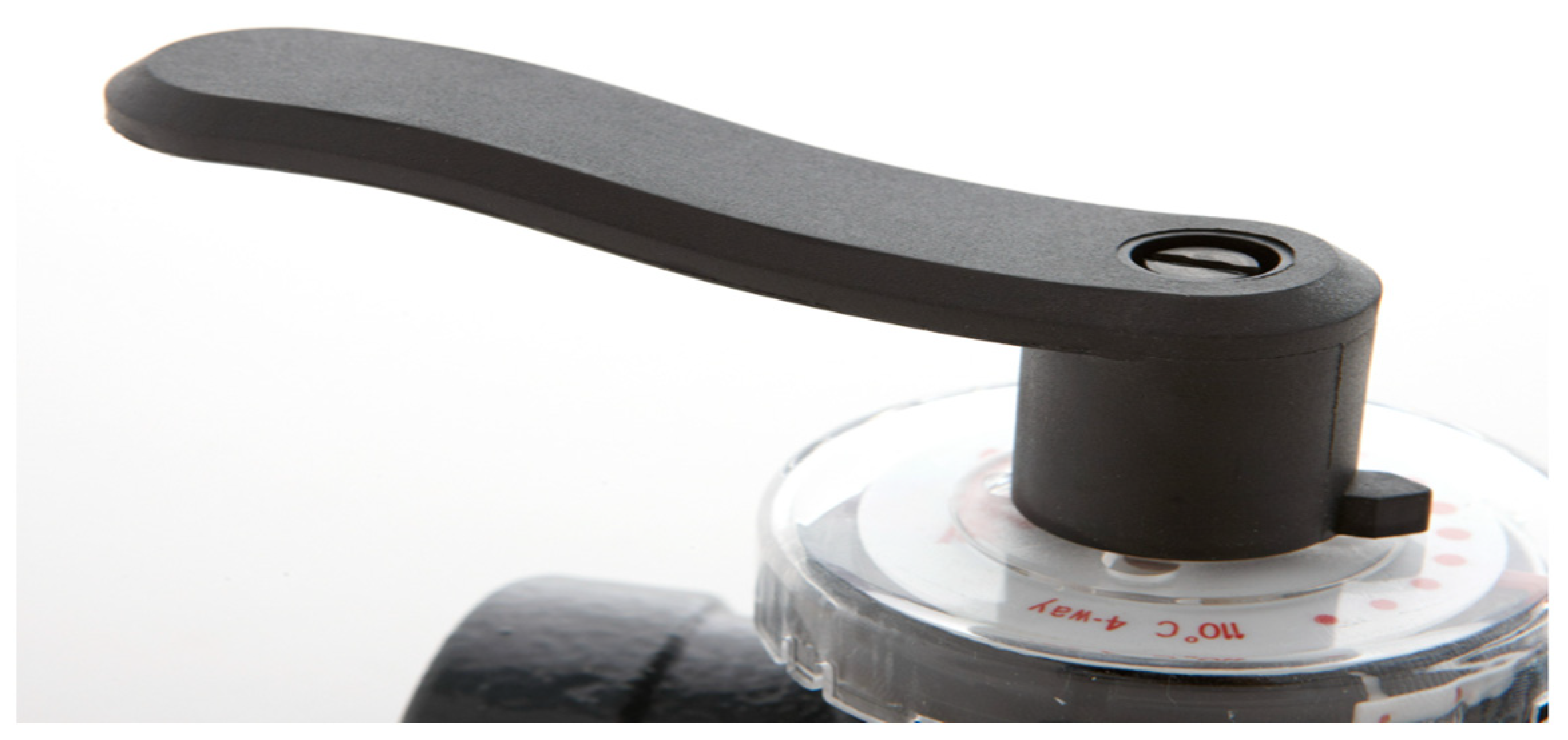
- Indicator:Usually mounted on the valve lever, this is built in the form of a round element with a transparent cover glass pane enabling the reading of parameters.
- Lever:The second movable part of the structure controls the valve shutter in the direction selected by the user. The lever is most often constructed in the form of a handle or a round control knob. The element has a description of functions depending on the direction of rotation of the lever.
- Regulation of the direction of medium flow.
- Medium temperature.
- Mixing the medium.
- Limit the reverse flow of the medium.
- Temperature optimization—parameter adjustment allows one to adjust the temperature in such a way that energy consumption is lower.
- Boiler safety—regulation function protects system elements against too low or too high a temperature, protecting against corrosion or condensation.
- Improved efficiency—maintains the temperature at a specific temperature, stabilizing the refrigerant flow, and improving the effective process of refrigerant flow and energy use in the system.
- Improvement of thermal comfort, i.e., satisfaction obtained from the environmental conditions in which one lives—This is the result of the balance between the loss of the environment and the amount of heat produced by the body.
- Heating, ventilation, and air conditioning (HVAC) systems: In air conditioning and heating systems, four-way valves allow precise control of the air temperature in rooms by mixing warm and cool media. In ventilation systems, they can be used to regulate airflow and temperature inside buildings.
- Heating and cooling systems: In underfloor heating or cooling systems, four-way valves can regulate the temperature of the liquid circulating through the installation, ensuring thermal comfort for users. In heating systems, these valves can control the temperature of the heating liquid, which allows one to adjust the temperature in individual zones of the building.
- Industrial processes: In the chemical industry, four-way valves can be used to mix various chemicals in specific proportions. In industrial cooling systems, these valves enable process temperature control production.
- Water cooling systems: In water cooling systems, four-way valves can regulate the flow of cooling and hot water, which allows one to maintain the optimal temperature in the cooling circuit.
- Sanitary installations: In the hot- and cold-water supply systems of residential or commercial buildings, four-way valves can help maintain a stable water temperature for the needs of users.
- Food industry: In the food industry, four-way valves can be used to mix and control the temperature of ingredients during the food production process.
- Energy: In some energy production systems, four-way valves can help regulate the flow of cooling or heating medium to maintain optimal operating conditions.
- System understanding: Identify the type of system in which the four-way valve will be used (e.g., HVAC, heating system, chemical industry, etc.).
- Required parameters: Specify what parameters will be controlled by the valve (e.g., liquid temperature, medium flow) and select the value ranges in which these parameters will change in the system.
- Size and capacity: Select the appropriate valve size that will allow substances to flow through the system. The valve size should be compatible with the flow of the medium.
- Valve type: Four-way valves come in various types, such as ball valves, rotary valves, and shaped valves. The type that best suits the characteristics of the medium and system requirements should be selected.
- Material: The material from which the valve is made, depending on the type of medium with which it will work (e.g., stainless steel, bronze, cast iron), should be selected.
- Control: One should decide whether the valve will be controlled manually or automatically. In some systems, automatic control can be more effective and precise.
- Application: One should ensure that the valve selected will be suitable for the specific application and whether it will be temperature control in an HVAC system or flow regulation in an industrial installation.
- Energy efficiency: For HVAC or other systems in which energy efficiency is important, one should select a valve with low-pressure loss and a well-matched flow profile.
3. Materials and Methods
3.1. Design Stages of a Four-Way Valve
- Gross weight: 3325 kg.
- Net weight: 3300 kg.
- Capacity: 5598 dm3.
- S-type flow characteristics.
- Nominal pressure: 10 bar.
- Construction materials, DZR brass CuZn36Pb2AS (602N).
- Valve design in SolidWorks.
- Four-way valve tests: cause-and-effect analysis of potential defects in the designed structure (FMEA) and strength tests aimed at selecting material for the structure.
- Static analysis of a four-way valve within the framework of sustainable development.
3.2. Cause and Effect Analysis of Potential Structural Defects (FMEA)
- Valve body.
- Flow channels.
- Gate.
- Connection of the valve with the lever.
- Threading the connection to the installation.
- Manual lever.
- Actuator regulator.
- Sealing kit.
3.3. Strength Tests in SolidWorks Software
- Calculation of heat flow in adiabatic wall approximations or solid objects.
- Determination of different types of heat sources.
- Assigning models a wide range of solid materials, stored in the engineering database.
- Defining one’s materials by assigning them values for such physical properties as thermal conductivity, heat capacity, etc.
- Calculation of radiant heat. The engineering database includes radiating surfaces such as blackbody walls, whitebody walls, graybody with any albedo, and a wide range of real material surfaces.
- Flow analysis of up to ten different types of fluids (liquids, gases/vapors, real gases, non-Newtonian fluids and compressible fluids). The database contains many fluids with defined properties.
- Analysis of a problem containing many fluids of different types, provided that the areas of different fluids are separated from each other using fluid subdomains.
- Fluid mutual dilution analysis. The mixing fluids must be of the same type.
- Definition of the fluids.
4. Results and Discussion
4.1. Design Stages of a Four-Way Valve
4.2. Cause and Effect Analysis of Potential Structural Defects (FMEA)
4.3. Strength Tests in SolidWorks Software
4.4. Four-Way Valve and Sustainable Development
- δ—material layer thickness,
- λf—thermal conductivity coefficient,
- Rf—thermal resistance of the material layer.
5. Conclusions
- These methods are useful for analyzing flow phenomena occurring in valves commonly used in various hydraulic installations.
- One can use the application programming interface (API) of SolidWorks programs to automate the process of shaping and optimizing the geometry of valve elements.
- The values of hydraulic forces acting on valve elements determined in simulation tests are similar to those in the catalog. This allows us to conclude that the effects of the liquid’s impact on the moving parts of the valve can be determined using the proposed simulation methods. It is possible to shape the pressure and flow characteristics of the valve by modifying the geometry of the valve elements.
- Using simulation models, it is possible to correct the unfavorable impact of hydrodynamic values within a given range of volume flow rate.
- The built models can be used for further analyses and development work.
- The valve model will be subjected to measurements of hydraulic forces and may be further developed and focused on application work in order to further improve the design of valve components.
- Analyses should be conducted in order to develop valve designs focused on new, ecological working media and construction materials.
- Development of models correcting the unfavorable effects of hydrodynamic forces.
Author Contributions
Funding
Data Availability Statement
Conflicts of Interest
Abbreviations
| HVAC | Heating, ventilation, and air conditioning |
| GWP | Global warming potential index |
| ODP | Ozone depletion potential |
| CFC/HCFC | Refrigerants containing carbon and chlorine |
| HFC | Refrigerants containing carbon |
| CO2/NH3/HC | Factors of natural origin |
| HFO | Hydrogen fluoride refrigerants |
| KBZW1 | Design of the basic four-way valve body |
| ZDZC1 | Design of a basic gate with a lever |
| ZDZC2 | Design of an alternative shutter with a regulator |
| FMEA | Failure mode and effects analysis |
References
- Yan, Q.; Li, D.; Wang, K.; Zheng, G. Study on the Hydrodynamic Evolution Mechanism and Drift Flow Patterns of Pipeline Gas-Liquid Flow. Processes 2024, 12, 695. [Google Scholar] [CrossRef]
- Zheng, G.; Xu, P.; Li, L.; Fan, X. Investigations of the Formation Mechanism and Pressure Pulsation Characteristics of Pipeline Gas-Liquid Slug Flows. J. Mar. Sci. Eng. 2024, 12, 590. [Google Scholar] [CrossRef]
- Finlayson-Pitts, B.J.; Pitts, J.N., Jr. Chemistry of the Upper and Lower Atmosphere; Elsevier Inc.: Amsterdam, The Netherlands, 2000; Volume 6, pp. 1–29. [Google Scholar]
- Arora, C.P. Refrigeration and Air Conditioning; Tata McGraw-Hill Publishing Company Limited: New York, NY, USA, 2000; Volume 11, pp. 30–56. [Google Scholar]
- Główny Urząd Statystyczny. Poziom Zużycia Energii na Ogrzewanie w Gospodarstwach Domowych w Polsce; Główny Urząd Statystyczny: Warsaw, Poland, 2021. [Google Scholar]
- Danfoss Poland Product Store. HRB 4, 40.00 m³/h, Rp 2, Zawory do Układów Centralnego Ogrzewania, Zawory Obrotowe, Zawory Regulacyjne z Siłownikiem Elektrycznym, Climate Solutions dla Ogrzewnictwa; Danfoss Poland Product Store: Warsaw, Poland, 2024. [Google Scholar]
- Andrew, D.; Althouse, C.H.; Turnquist, I.; Alfred, F. Bracciano, Modern Refrigeration and Air Conditioning, 18th ed.; Goodheart-Willcox: Tinley Park, IN, USA, 2019; Volume 7, pp. 30–65. [Google Scholar]
- Tomczyk, J.; Silberstein, E.; Whitman, W.C.; Johnson, W.M. Refrigeration and Air Conditioning Technology; Cengage Learning: Boston, MA, USA, 2016; Volume 10, pp. 30–48. [Google Scholar]
- Niekurzak, M. The Potential of Using Renewable Energy Sources in Poland Taking into Account the Economic and Ecological Conditions. Energies 2021, 14, 7525. [Google Scholar] [CrossRef]
- American Society of Heating, Refrigerating and Air-Conditioning Engineers. ASHRAE Handbook—HVAC Systems and Equipment, 9, 19, 20, 24; ASHRAE: Peachtree Corners, GA, USA, 2020. [Google Scholar]
- Mitchell, J.W.; Braun, J.E. Principles of Heating, Ventilation, and Air Conditioning in Buildings; John Wiley & Sons: Hoboken, NJ, USA, 2014; Volume 8, pp. 1–40. [Google Scholar]
- McQuiston, F.C.; Parker, J.D.; Spitler, J.D.; Taherian, H. Spitler, Heating, Ventilating and Air Conditioning Analysis and Design, 6th ed.; Wiley: Hoboken, NJ, USA, 2023; Volume 9, pp. 4–50. [Google Scholar]
- Gohari, H. Air Conditioning and Refrigeration Repair Made Easy; Xlibris Corp.: Bloomington, IN, USA, 2009; Volume 6, pp. 20–56. [Google Scholar]
- Afriso Sp. Z o. o. Sterownik Delta 2003d + Siłownik Proclick, str. 69. 2023. Available online: https://sterownikitech.pl/zestaw-afriso-sterownik-i-silownik-z-zestawem-montazowym,id1136.html (accessed on 10 January 2024).
- Soliński, B. Analiza Przyczyn Wadliwości i Krytyczności Wad. Available online: https://www.zarz.agh.edu.pl/bsolinsk/fmea.html (accessed on 10 January 2024).
- Mikulak, R.J.; McDermott, R.; Beauregard, M. The Basics of FMEA; CRC Press: Boca Raton, FL, USA, 2017; Volume 5, pp. 23–47. [Google Scholar]
- Tomczyk, J. Troubleshooting and Servicing Modern Air Conditioning and Refrigeration Systems, 2nd ed.; Esco Press: Essex, UK, 1995; Volume 3, pp. 1–68. [Google Scholar]
- Niekurzak, M.; Mikulik, J. Modeling of Energy Consumption and Reduction of Pollutant Emissions in a Walking Beam Furnace Using the Expert Method—Case Study. Energies 2021, 14, 8099. [Google Scholar] [CrossRef]
- Zawadzki, P. Engineering Analysis with SOLIDWORKS Simulation; SDC Publications: Mission, KS, USA, 2022; Volume 5, pp. 1–47. [Google Scholar]
- George, F. Limbrunner i Craig D’Allaird, Applied Statics and Strength of Materials, 6th ed.; Pearson: London, UK, 2015; ISBN 9780133840544. [Google Scholar]
- Roberta, H. King, Finite Element Analysis with SOLIDWORKS Simulation, 1st ed.; Cengage Learning: Boston, MA, USA, 2018; Volume 2, pp. 1–32. [Google Scholar]
- Kubiński, W. Materiałoznawstwo. Tom 1. Podstawowe Materiały Stosowane w Technice; Wydawnictwo AGH: Kraków, Poland, 2012; pp. 1–155. [Google Scholar]
- Chartered Institution of Building Services Engineers. Energy Efficiency in Buildings: CIBSE Guide F; CIBSE: London, UK, 2012; Volume 2, pp. 1–30. [Google Scholar]
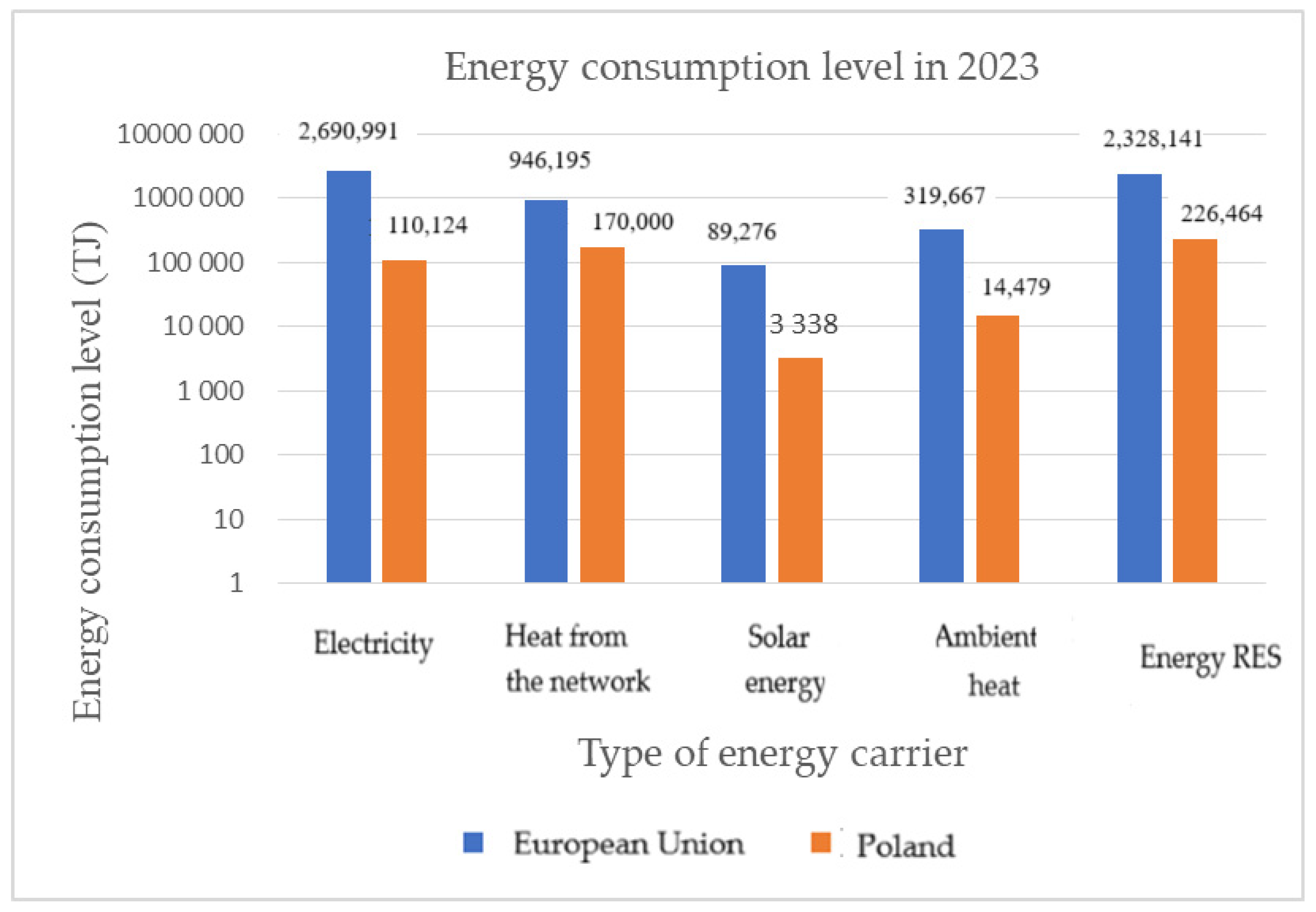
- Główny Urząd Statystyczny. Zużycie Energii w Gospodarstwach Domowych w Podziale na nośniki Energii w Polsce i Krajach Unii Europejskiej oraz udział Poszczególnych Krajów w Zużyciu Energii w UE-28. 2021. Available online: https://stat.gov.pl/obszary-tematyczne/srodowisko-energia/energia/zuzycie-energii-w-gospodarstwach-domowych-w-2021-roku,12,2.html (accessed on 15 January 2024).
- Lechner, N. Heating, Cooling, Lighting: Sustainable Design Methods for Architects, 3rd ed.; John Wiley & Sons: Hoboken, NJ, USA, 2008; ISBN 0470048093. [Google Scholar]
- IMI Hydronic Engineering, Efektywność Energetyczna Instalacji Hydraulicznych, Breakthrough Engineering, 2–55. Available online: https://www.imi-hydronic.com/pl-pl (accessed on 10 January 2024).
- Niekurzak, M.; Lewicki, W.; Drożdż, W.; Miązek, P. Measures for Assessing the Effectiveness of Investments for Electricity and Heat Generation from the Hybrid Cooperation of a Photovoltaic Installation with a Heat Pump on the Example of a Household. Energies 2022, 15, 6089. [Google Scholar] [CrossRef]
- Olczak, P.; Olek, M.; Matuszewska, D.; Dyczko, A.; Mania, T. Monofacial and Bifacial Micro PV Installation as Element of Energy Transition-The Case of Poland. Energies 2021, 14, 499. [Google Scholar] [CrossRef]
- Tamburrano, P.; Plummer, A.R.; Distaso, E.; Amirante, R. A review of electro-hydraulic servo valve research and development. Int. J. Fluid. Power 2019, 20, 53–98. [Google Scholar]
- Tamburrano, P.; Plummer, A.R.; Distaso, E.; Amirante, R. A review of direct drive proportional electrohydraulic spool valves: Industrial state-of-the-art and research advancements. J. Dyn. Syst. Meas. Control Trans. ASME 2019, 141, 020801. [Google Scholar] [CrossRef]
- Zhu, Q.; Huang, D.; Yu, B.; Ba, K.; Kong, X.; Wang, S. An improved method combined SMC and MLESO for impedance control of legged robots’ electro-hydraulic servo system. ISA Trans. 2022, 130, 598–609. [Google Scholar] [CrossRef]
- Chen, X.; Jiao, Z.; Liu, X.; Li, X.; Qi, P.; Shang, Y. Experimental validation of a practical nonlinear control method for hydraulic flight motion simulator. J. Frankl. Inst. 2022, 359, 2405–2423. [Google Scholar] [CrossRef]
- Fan, Y.L.; Lei, Y.; Zhang, J.W.; Wang, J.; Li, Z. Flow Force of Pressure Independent Control Valve with Different Valve Core Structural. J. Phys. Conf. Ser. 2020, 1634, 12149. [Google Scholar] [CrossRef]
- Li, R.; Sun, Y.; Wu, X.; Zhang, P.; Li, D.; Lin, J.; Xia, Y.; Sun, Q. Review of the Research on and Optimization of the Flow Force of Hydraulic Spool Valves. Processes 2023, 11, 2183. [Google Scholar] [CrossRef]
- Gao, Q.; Wang, J.; Zhu, Y.; Wang, J.; Wang, J. Research Status and Prospects of Control Strategies for High Speed on/off Valves. Processes 2023, 11, 160. [Google Scholar] [CrossRef]
- Wang, H.; Chen, Z.; Huang, J.; Quan, L.; Zhao, B. Development of high-speed on-off valves and their applications. Chin. J. Mech. Eng. 2022, 35, 67. [Google Scholar] [CrossRef]
- Karpenko, M.; Stosiak, M.; Šukevičius, Š.; Skačkauskas, P.; Urbanowicz, K.; Deptuła, A. Hydrodynamic Processes in Angular Fitting Connections of a Transport Machine’s Hydraulic Drive. Machines 2023, 11, 355. [Google Scholar] [CrossRef]
- Li, L.; Gu, Z.H.; Xu, W.X.; Tan, Y.F.; Fan, X.H.; Tan, D.P. Mixing mass transfer mechanism and dynamic control of gas–liquid–solid multiphase flow based on VOF-DEM coupling. Energy 2023, 272, 127015. [Google Scholar] [CrossRef]
- Ge, M.; Zheng, G.A. Fluid-solid mixing transfer mechanism and flow patterns of the double-layered impeller stirring tank by the CFD-DEM method. Energies 2024, 17, 1513. [Google Scholar] [CrossRef]
- Borowski, P. Adaptation strategy on regulated markets of power companies in Poland. Energy Environ. 2019, 30, 3–26. [Google Scholar] [CrossRef]
- Kochanek, E. Wielowymiarowość Interesów Energetycznych w Dobie Transformacji Systemowej; WAT: Warsaw, Poland, 2021. [Google Scholar]
- Niekurzak, M.; Kubińska-Jabcoń, E. Analysis of the Return on Investment in Solar Collectors on the Example of a Household: The Case of Poland. Front. Energy Res. 2021, 9, 224. [Google Scholar] [CrossRef]
- Polityka Energetyczna Polski 2040, Załacznik do Uchwały nr 22/2021 Rady Ministrów z Dnia 2 Lutego 2021 r; Ministerstwo Klimatu i środowiska: Warsaw, Poland, 2021.
- Szczerbowski, R. The forecast of Polish power production sector development by 2050—Coal scenario. Energy Policy J. 2018, 19, 5–18. [Google Scholar]
- Figołuszka, S. Projekt zaworu Czterodrogowego do Instalacji Centralnego Ogrzewania Budynków z Wykorzystaniem Modelowania Bryłowego. Engineering Thesis, AGH, Kraków, Poland, 2023, unpublished materials. [Google Scholar]
- Robaina, M.; Neves, A. Complete decomposition analysis of CO2 emissions intensity in the transport sector in Europe. Res. Transp. Econ. 2021, 87, 101074. [Google Scholar] [CrossRef]






| Speech | FMEA of the Valve Element | R-Value | Probability of Occurrence |
|---|---|---|---|
| R index | |||
| Unbelievable | The occurrence of a defect is unlikely | 1 | less than 1 in 1,000,000 |
| Very rarely | There are relatively few defects | 2 | 1 in 20,000 |
| Rarely | There are relatively few defects | 3 | 1 in 4000 |
| On average | The defect occurs sporadically from time to time | 4–6 | 1 in 1000 |
| Often | The defect repeats itself cyclically | 7–8 | 1 in 40 |
| Very often | The flaw is almost impossible to avoid | 9–10 | 1 in 8 |
| Defect Detectability | The Probability of Detecting a Defect | W | |
| W index | |||
| Very high | Very low probability of not detecting a defect before the product leaves the manufacturing process. Automatic inspection of 100% of elements, and installation of protection. | 1–2 | |
| High | Low probability of failure to detect a defect | 3–4 | |
| Average | Medium Probability of not detecting a defect | 5–6 | |
| Low | The probability of not detecting a defect | 7–8 | |
| Very low | The probability of not detecting a defect | 9–10 | |
| The Importance of the Defect for the Customer | Z | ||
| Z index | |||
| Very small | Minimal effect, the customer does not notice anything, and the defect does not have any impact on the conditions of the use of the product | 1 | |
| Small | Minimal effect, causing minor disruption. A moderate deterioration in the product’s properties may be noticeable. | 2–3 | |
| Average | The defect causes limited dissatisfaction and causes little inconvenience. The product does not meet the needs or is a source of nuisance. The user notices the product’s shortcomings. | 4–6 | |
| High | Customer dissatisfaction occurs. Repair cost unknown | 7–8 | |
| Very high | High customer dissatisfaction. High repair cost due to failure of the entire unit or component. | 9 | |
| Very high | The significance of the defect is very high, it threatens the user’s safety and violates the provisions of the standards. | 10 | |
| No. | Element of Construction | Potential Defect | Effects of the Defect | Cause of the Defect | Control Methods Used | R | W | Z | PR | Recommended Actions Taken | R | W | Z | PR |
|---|---|---|---|---|---|---|---|---|---|---|---|---|---|---|
| Current Status | Results of Actions | |||||||||||||
| 1 | Valve body | Corrosion, deformation of the structure | Refrigerant leaking outside the system | Inappropriate material | Strength analysis of the material used | 2 | 2 | 10 | 40 | Selection of corrosion-resistant material | 1 | 2 | 10 | 20 |
| 2 | Flow channels | Blocked medium flow | Interruption of the operation of a system that includes a four-way valve | Inadequate pressure or dimensions of the valve interior | Valve interior pressure measurement | 3 | 2 | 9 | 54 | Valve maintenance | 2 | 2 | 9 | 36 |
| 3 | Mirror | Seizure, stuck, limited mirror movement | Limitation or loss of control over the factor introduced into the system | Design errors, inappropriate material, lack of lubrication | Compatibility analysis of moving parts | 5 | 4 | 9 | 180 | Lubrication of moving parts | 4 | 3 | 9 | 108 |
| 4 | Connecting the mirror to the lever | Deformation (fractures, seizing, cracks), uncontrolled leakage | Loss of control over the valve seal | Inappropriate material, lack of seal between the moving part and the valve body | Valve geometry analysis | 3 | 2 | 10 | 60 | Protecting sensitive parts against wear | 3 | 1 | 10 | 30 |
| 5 | Threaded connections to the installation | Thread damage | Inability to connect the installation to the valve | Wrong way to install the installation | Visual inspection | 6 | 2 | 7 | 84 | Protecting sensitive parts against wear | 6 | 1 | 7 | 42 |
| 6 | Manual lever | Deformation, fracture | Loss of control over the valve seal | Lever design errors | Geometry and strength analysis | 4 | 2 | 9 | 72 | Replacing the lever | 4 | 2 | 9 | 72 |
| 7 | Actuator regulator | Actuator failure, loss of connection between the controller and the actuator | Loss of control over medium flow parameters | Too high voltage, humidity | Control of actuator operating parameters | 6 | 2 | 9 | 108 | Resetting actuator operating parameters | 4 | 1 | 9 | 36 |
| 8 | Sealing kit | Damage to the sealing set | Uncontrolled refrigerant leakage, pressure drop | Ageing, not replacing the seal kit | Measurement of pressure inside the valve, tightness check | 7 | 4 | 7 | 196 | Replacing the seal kit | 5 | 2 | 7 | 70 |
| No. | The Value of the Applied Force, N | Type of Material | The Plane of Force Application | Result of Statistical Analysis | |
|---|---|---|---|---|---|
| Tension (VON), MPa | Deformation (ESTRN) | ||||
| 1 | 0.5 | Brass | The connection plane with the installation | 0.01 | 5.40 × 10⁻⁸ |
| Mirror plane | 0.06 | 2.39 × 10⁻⁷ | |||
| 2 | Stainless steel | The connection plane with the installation | 0.07 | 4.45 × 10⁻⁸ | |
| Mirror plane | 0.06 | 2.44 × 10⁻⁷ | |||
| 3 | Brown | The connection plane with the installation | 0.07 | 4.38 × 10⁻⁸ | |
| Mirror plane | 0.06 | 2.15 × 10⁻⁷ | |||
| 4 | Cast iron | The connection plane with the installation | 1.07 × 10⁴ | 4.93 × 10⁻⁸ | |
| Mirror plane | 6.43 × 10⁴ | 2.15 × 10⁻⁷ | |||
| 5 | Carbon steel | The connection plane with the installation | 1.09 × 10⁴ | 2.58 × 10⁻⁸ | |
| Mirror plane | 6.47 × 10⁴ | 1.11 × 10⁻⁷ | |||
| Poisson’s Ratio | Tensile Strength, MPa | Yield Strength, MPa | |
|---|---|---|---|
| Brass | 0.33 | 478.4 | 239.7 |
| Stainless steel | 0.27 | 685.0 | 292.0 |
| Brown | 0.30 | 55.1 | 275.7 |
| Cast iron | 0.31 | 861.7 | 551.5 |
| Carbon steel | 0.28 | 399.8 | 220.6 |
| Thickness of the Contamination Layer | 0 mm | 0.17 mm | 0.35 mm |
| Coefficient of performance (COP) | 2.84 | −2.50% | −5.30% |
| Δp evaporator | 53 kPa | 3.10% | 8.70% |
Disclaimer/Publisher’s Note: The statements, opinions and data contained in all publications are solely those of the individual author(s) and contributor(s) and not of MDPI and/or the editor(s). MDPI and/or the editor(s) disclaim responsibility for any injury to people or property resulting from any ideas, methods, instructions or products referred to in the content. |
© 2024 by the authors. Licensee MDPI, Basel, Switzerland. This article is an open access article distributed under the terms and conditions of the Creative Commons Attribution (CC BY) license (https://creativecommons.org/licenses/by/4.0/).
Share and Cite
Niekurzak, M.; Mikulik, J. Design and Experimental Tests of a Four-Way Valve with the Determination of Flow Characteristics for Building Central Heating Installations Using Solid Modeling. Energies 2024, 17, 2152. https://doi.org/10.3390/en17092152
Niekurzak M, Mikulik J. Design and Experimental Tests of a Four-Way Valve with the Determination of Flow Characteristics for Building Central Heating Installations Using Solid Modeling. Energies. 2024; 17(9):2152. https://doi.org/10.3390/en17092152
Chicago/Turabian StyleNiekurzak, Mariusz, and Jerzy Mikulik. 2024. "Design and Experimental Tests of a Four-Way Valve with the Determination of Flow Characteristics for Building Central Heating Installations Using Solid Modeling" Energies 17, no. 9: 2152. https://doi.org/10.3390/en17092152
APA StyleNiekurzak, M., & Mikulik, J. (2024). Design and Experimental Tests of a Four-Way Valve with the Determination of Flow Characteristics for Building Central Heating Installations Using Solid Modeling. Energies, 17(9), 2152. https://doi.org/10.3390/en17092152


