Article

Design and Implementation of Hybrid GA-PSO-Based Harmonic Mitigation Technique for Modified Packed U-Cell Inverters

by
Hasan Iqbal
* and
Arif Sarwat
*
Department of Electrical and Computer Engineering, Florida International University, Miami, FL 33174, USA
*
Authors to whom correspondence should be addressed.
Energies 2025, 18(1), 124; https://doi.org/10.3390/en18010124
Submission received: 19 November 2024 / Revised: 23 December 2024 / Accepted: 30 December 2024 / Published: 31 December 2024
(This article belongs to the Special Issue Voltage/Frequency/Power Quality Monitoring and Control in Smart Grids)

Abstract

:
Multilevel inverters have gained importance in modern power systems during the last few years because of their high power quality with lower THD. Various topologies developed include the packed U-cell inverter and its different modified versions that have emerged as a compact and efficient solution to distributed energy systems. Most of the available harmonic mitigation techniques, that is, passive filtering and individual optimization techniques, which include GA and PSO, are susceptible to a variety of shortcomings regarding their inherent complexity and inefficiency; hence, finding an appropriate convergence may be quite hard. This paper proposes a hybrid version of the GA-PSO algorithm that exploits the exploratory strengths of GA and the convergence efficiencies of PSO in determining the optimized switching angles for SHM techniques applied to modified five-level and seven-level PUC inverters. By utilizing the multi-objective optimization method, the approach minimizes THD while keeping voltage and efficiency constraints. Simulated in MATLAB/Simulink, the results were experimentally verified using hardware-in-the-loop testing on OP5700. A large THD reduction in both MPUC7 (11.68%) and MPUC5 (17.61%) was obtained. The proposed hybrid algorithm outperformed the standalone approaches of GA and PSO with respect to robustness and with precise harmonic suppression. Other appealing features are reduced computational complexity and improved waveform quality; hence, the method is highly suitable for both grid-tied and standalone renewable energy applications. This work lays a basis for efficient inverter designs that can adapt well under dynamic load conditions.

1. Introduction

1.1. Background on Multilevel Inverters and Their Significance in Power Systems

Working principles of multilevel inverters (MLIs) are at the heart of modern power systems, while their benefit compared to two-level inverters is considerable. Due to synthesizing output waveforms with many voltage levels, MLIs allow better power quality and lower total harmonic distortion (THD) in addition to higher voltage capability. These are the features that make MLIs very relevant in the integration of renewable energies, electric drives, and industrial motor drives. Among the various multilevel inverter topologies, packed U-cell inverters and their variants have emerged as a promising solution owing to their compact structure, reduced component count, and high boosting capability [1,2].
The increasing penetration of MLIs into DERs, in turn, underlines their importance. In DER-integrated systems, the inverter has to ensure stable grid operations in light of dynamic load conditions. Assurance of optimum performance from such systems depends on harmonics mitigation and efficiency in energy conversion. Hence, harmonic mitigation becomes central to the operation of MLIs while dealing with a grid-connected renewable energy source [3,4].

1.2. Challenges with Harmonics in Multilevel Inverters

Multilevel inverters have become one of the keystones for modern power electronics since they allow for achieving high-quality output waveforms while keeping the component stresses low. Among these successful MLI topologies, there are the Cascaded H-Bridge (CHB), Flying Capacitor (FC), and Neutral Point Clamped (NPC) inverters. Each has its advantages and a number of challenges [5,6,7,8].
The CHB topology is one of the most attractive multilevel topologies because it is modular in nature; hence, scalability with fault tolerance operation is an excellent feature. However, the application of many DC sources in isolation complicates its application in some fields. Similarly, flexibility in voltage level is achieved with the use of capacitors in the FC inverter, but balancing capacitor voltages through different operating conditions has become a tough task. In the NPC inverter, there are clamping diodes that perform voltage sharing effectively and decrease harmonic distortion, but at higher levels, it also suffers from increased complexity with more losses related to diodes [9,10].
Traditional MLI topologies, despite their advantage, often involve trade-offs among efficiency, complexity, and harmonic performance. Because of nonlinear switching operations, harmonic distortion is prevalent among all designs of MLI, which causes power quality issues in the form of increased losses, overheating, and possible interference with sensitive equipment [11,12].
The packed U-cell inverter has been developed as an alternative that unites all the positive features of these classic topologies and overcomes some of their drawbacks. Its compact and cost-effective design covers the reduced number of components. Due to its inherent boosting capability, the PUC inverter seems to be especially promising for applications requiring high voltage gain. However, these advantages introduce unique challenges [13,14].
In five-level and seven-level PUC inverters, low harmonic content must be maintained to meet international standards such as IEEE 519 [15]. The PUC inverter does not include the topology of a CHB or NPC; therefore, without an optimized operation, it can experience increased voltage stress along with irregularity in the switching. Conventional techniques for harmonic mitigation include either very extensive filtering or the use of complex control schemes. Often, these defeat the simplicity and cost-effectiveness that the PUC topology possesses.
These challenges require the application of sophisticated control strategies that are suited to the specific needs of five-level and seven-level PUC inverters. Realizing an optimum trade-off between harmonic suppression, voltage stress minimization, and operational efficiency is crucial in unfolding the entire gamut of PUC inverters for modern power systems. Optimization-based techniques, including hybrid algorithms like GA-PSO, therefore become essential in handling these conflicting objectives with some degree of efficiency.

1.3. Overview of Optimization Techniques Used for Harmonic Mitigation

Extensive research has been carried out on harmonic mitigation in MLIs, out of which optimization-based techniques have gained much popularity. The aim of these techniques is to find optimal switching angles or control parameters that will minimize certain harmonic orders while maintaining a desired output waveform. The most commonly employed methods include the GA and PSO, inspired by natural processes [16,17].
Genetic algorithms are evolutionary techniques that conduct their search in the solution space by emulating selection, crossover, and mutation. These are generally found to be effective in nonlinear or multi-objective problems such as harmonic elimination. The PSO technique is inspired by the social behavior of particles. This technique uses collective intelligence to converge on an optimal solution. Its ease, quick convergence, and scalability features make PSO a preferred choice for control applications in power electronics [8].
Nevertheless, all these methods have their own deficiencies. GAs may suffer from early convergence and high computational expenses, while PSO can easily get trapped into the local optima. These kinds of problems drive one into seeking a hybrid approach aimed at overcoming the weakness of the individual algorithms and achieving superior performance using their combined strength.

1.4. Motivation for Combining GA and PSO for Selective Harmonic Mitigation (SHM)

The rationale behind combining the GA and PSO is due to their complementary nature. While the GA offers a superior exploration of diverse regions in the solution space, PSO provides faster convergence toward local optima. This hybrid approach by combining the GA and PSO will leverage these strengths to address the rather complicated problem of harmonic mitigation in PUC inverters [18].
SHM selects a number of specific harmonic orders to be mitigated while letting the rest pass, provided their presence does not appreciably deteriorate the performance. Compared with traditional THD minimization, this “selected” harmonic elimination process reduces the computational burden and therefore is more amenable to real-time applications. Optimal SHM of the PUC inverters nevertheless requires a subtle understanding of the trade-offs between harmonic elimination, switching losses, and voltage stress [14].
A hybrid GA-PSO algorithm would provide a sound platform for these trade-offs. The approach ensures diversity and precision in the population initialization through the GA and refinement of solutions through PSO. This methodology not only enhances harmonic suppression but also improves the overall efficiency and reliability of the inverter.

1.5. Objectives of the Study

The present work serves as a study for developing and validating a hybrid algorithm for harmonic mitigation in modified five-level and seven-level PUC inverters. The objectives are as follows:
  • Formulate the harmonic mitigation problem as a multi-objective optimization problem with minimum THD serving as the primary objective, while keeping voltage stress and switching loss constraints.
  • Design a hybrid GA-PSO algorithm that combines the exploratory power of the GA with the convergence efficiency of PSO.
  • Simulate the proposed approach in MATLAB/Simulink 2023b to evaluate its effectiveness in reducing harmonic content in five-level and seven-level PUC inverters.
  • Offer a real-time implementation of the proposed system using the OPAT-RT OP5700 platform to evaluate the performance in real-time.
  • Benchmark the hybrid algorithm against standalone GA and PSO methods to demonstrate its superiority.
  • Explore the feasibility of hardware implementation to validate the algorithm’s performance under practical conditions.
By addressing these objectives, This paper proposes a new hybrid GA-PSO optimization technique, which draws on the exploratory power of the GA and the convergence efficiency of PSO for the harmonic mitigation of MPUC inverters. Unlike traditional methods that rely heavily on standalone optimization algorithms, our proposed hybrid approach demonstrates better harmonic suppression with reduced computational complexity. Furthermore, this work verifies the proposed method by using the OP5700 platform for hardware-in-the-loop testing to ensure practical applicability. Compared to the works in the literature, the work presented here uniquely focuses on dynamic load condition and voltage stress minimization challenges by providing a robust solution in both grid-connected and standalone renewable energy systems.
The rest of the paper is organized as follows. Section 2 reviews the literature on topologies of MLIs, harmonic mitigation techniques, and the requirement of the proposed hybrid GA-PSO optimization technique. Section 3 describes the architecture of seven-level PUC and five-level PUC inverters and the problem formulation is given in Section 4 concerning the harmonic mitigation of these inverters. Section 5 describes the implementation of the proposed hybrid GA-PSO optimization using Python 3.13.0 along with MATLAB/Simulink 2023b. Simulation and modeling of the proposed optimization techniques based mitigation control are given in Section 6 as well as a description of the setup for the real-time experimental validation and the related results. Finally, Section 7 summarizes the contributions of the paper by discussing its limitations and pointing out possible future research directions.

2. Literature Review

2.1. Existing Multilevel Inverter Topologies

Multilevel inverters have indeed brought an power electronics revolution for efficient and high-quality AC voltage generation by using multiple discrete voltage levels. Many topologies have been developed over the years in pursuit of MLIs to meet the demands for specific applications. The most used topologies are Cascaded H-Bridge, Flying Capacitor, Neutral Point Clamped, and packed U-cell inverters [5,6,7].

2.1.1. Cascaded H-Bridge (CHB) Inverter

The CHB inverter is well known for its modular configuration, in which single H-bridge modules are cascaded to achieve higher voltage levels. Such modularity grants fault tolerance, scalability, and ease of maintenance. In contrast, one disadvantage of the CHB inverter is that separate DC sources are required for each module; thus, their implementation is difficult in centralized systems or when renewable energy sources are not plentiful. The inherent simplicity of the control scheme and its effectiveness in reducing harmonics are responsible for making CHB a popular choice for medium- 0to high-voltage applications [5].

2.1.2. Flying Capacitor (FC) Inverter

The FC inverter uses capacitors to generate intermediate voltage levels; therefore, it does not require a lot of isolated DC sources. It provides flexibility in terms of the switching combinations for better voltage balancing and harmonic performance. The use of such a large amount of capacitors creates problems regarding voltage balancing at various conditions of load and weight, as well as cost increase at higher voltage levels [6].

2.1.3. Neutral Point Clamped (NPC) Inverter

NPC inverters employ diodes to clamp the neutral point, ensuring voltage sharing across the switching devices. This design minimizes voltage stress and achieves reduced harmonic distortion compared to traditional two-level inverters. Despite its advantages, NPC inverters suffer from increased complexity and losses associated with clamping diodes. Additionally, extending this topology to higher levels often results in higher component counts, making it less suitable for compact systems [7].

2.1.4. Packed U-Cell (PUC) Inverter

The PUC inverter addresses several challenges posed by the aforementioned topologies. By using fewer components and integrating boosting capabilities, the PUC inverter achieves a compact and cost-effective design. However, it still requires careful control to manage voltage stress and harmonics effectively. Its advantages make it a strong candidate for applications in distributed energy systems, particularly where space and cost constraints are critical. This work focuses on the modified PUC topology inverter, namely, a modified sevel-level PUC (PUC7) inverter and a modified five-level PUC inverter (PUC5). A proper topology description is given in the next section [13].
In summary, as compared in Table 1, it is evident that the PUC family of multilevel inverters, including PUC5 and PUC7, demonstrates significant superiority over NPC5, FLC5, and CHB5 in several critical aspects. PUC designs utilize fewer components, which enhances their practicality and cost efficiency. For example, while NPC5 and FLC5 require eight switches and multiple capacitors, with NPC5 using four and FLC5 using seven, PUC5 and PUC7 only use six switches and a minimal number of capacitors, just one in both cases. Furthermore, clamping diodes are completely eliminated in PUC designs, unlike NPC5 which uses six diodes, adding to the overall simplicity of the PUC topology. Importantly, the control complexity of PUC5 and PUC7 is either low or high, contrasting sharply with the very high control complexity associated with NPC5 and FLC5. These advantages make the PUC family more efficient, simpler to implement, and more cost-effective, clearly demonstrating its superiority over other multilevel inverter types.

2.2. Existing Harmonic Mitigation Techniques in MLIs

Harmonics are a significant concern in MLIs, as they degrade power quality and can damage equipment over time. Over the years, various harmonic mitigation techniques have been developed, which can be broadly categorized into passive, active, and optimization-based methods.

2.2.1. Passive Filtering Techniques

Passive filters are among the earliest methods employed to reduce harmonic distortion. By using inductors, capacitors, or resistors, these filters attenuate unwanted harmonics before they reach the grid. Although effective for specific harmonic orders, passive filters are bulky, less adaptive, and prone to resonance issues, making them unsuitable for modern dynamic loads [19].

2.2.2. Active Harmonic Control

Active harmonic control techniques use power electronic devices to actively suppress harmonics. For example, active filters and dynamic voltage restorer systems can adapt to varying load conditions and provide superior harmonic suppression. However, the high cost and complexity of these systems often limit their adoption in smaller-scale applications [20].

2.2.3. Optimization-Based Techniques

Optimization techniques have become indispensable for harmonic mitigation in multilevel inverters (MLIs), offering a flexible and efficient alternative to traditional filtering methods. These techniques focus on fine-tuning control variables, such as switching angles, to achieve specific objectives, primarily the reduction of Total Harmonic Distortion (THD). Here are some widely used and effective optimization-based methods:
  • Genetic Algorithm (GA): The genetic algorithm is a robust evolutionary technique inspired by natural selection principles. The GA has been extensively used for Selective Harmonic Elimination (SHE) in MLIs, where the objective is to eliminate specific lower-order harmonics while preserving the fundamental frequency. The GA’s ability to explore a broad solution space makes it effective in handling nonlinear problems like THD minimization. However, the GA can sometimes suffer from slow convergence and premature stagnation, especially when dealing with highly complex or multi-modal problems [14,21].
  • Particle Swarm Optimization (PSO): PSO is a population-based optimization technique inspired by the social behavior of birds and fish. It is widely used in MLIs for optimizing switching angles to reduce THD. PSO’s key advantage lies in its simplicity and rapid convergence to near-optimal solutions. However, its tendency to become trapped in local optima, particularly in high-dimensional search spaces, can limit its effectiveness in achieving the best possible harmonic suppression [22,23,24].
  • Differential Evolution (DE): Another robust and efficient evolutionary optimization technique for nonlinear and multi-modal problems is DE. In harmonic mitigation, DE has also been applied for the optimization of MLI parameters with often competitive results. Simplicity in mutation and selection further makes it particularly appealing for high-dimensional problems. However, optimal results may be obtained from DE after extensive tuning of its parameters [25].
  • Simulated Annealing (SA): SA is a probabilistic technique that simulates the annealing process in metallurgy. It has been applied to MLIs for the minimization of THD, where switching angles are progressively improved. In particular, SA has proved very effective in escaping local optima, although convergence rates are generally slower compared to PSO or GA methods [23,26].
  • Multi-Objective Optimization (MOO): There are multi-objective techniques, such as the Non-Dominated Sorting Genetic Algorithm-II (NSGA-II), which are applied to handle the conflict of objectives in harmonic mitigation, like minimization of THD at reduced switching losses or voltage stress. They offer a Pareto-optimal front that empowers the designer with several trade-off solutions, depending on the requirements of the application [27,28].

2.2.4. Limitations of Single Optimization Techniques

While these individual techniques of optimizations like GA and PSO apply to THD reduction, they have their inherent limitations. For instance, consider the following:
  • GA: Slow convergence and prematurely converges into local optima.
  • PSO: Premature convergence problem, especially in multi-modal search spaces.
  • SA and DE: Usually require extensive parameter tuning, which can be computationally expensive.
These challenges highlight the need for more robust approaches that can overcome the weaknesses of single optimization methods. This gives rise to our hybrid GA-PSO optimization technique. The hybrid GA-PSO technique integrates the exploratory capabilities of the GA with the exploitative efficiency of PSO. By using the GA in the initial stages, the algorithm explores a wide solution space to identify promising regions. PSO then fine-tunes the solutions in these regions, ensuring rapid convergence to optimal or near-optimal solutions. This combination addresses the key limitations of both methods. The formulation of hybrid GA-PSO is introduced properly in Section 5.

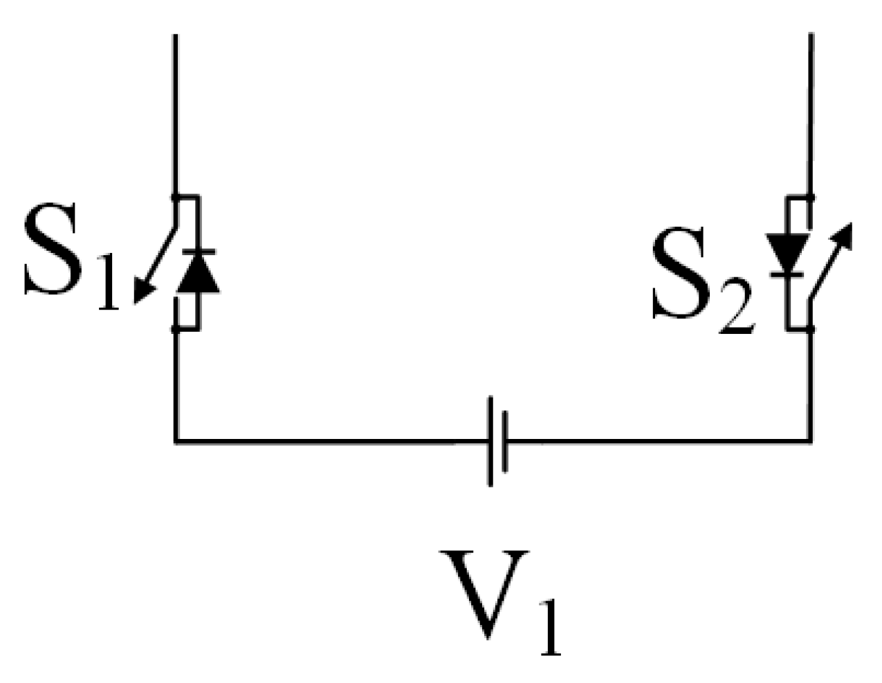
3. Packed U-Cell Inverters

The conventional single U-cell as shown in Figure 1 consists of two power switches along with one DC source [13]. The packed U-cell (PUC) inverter is made by repeating this single U-cell multiple times in well defined fashion. In this work, a modified seven-level PUC (MPUC7) inverter and a modified five-level PUC (MPUC5) inverter are discussed and the proposed hybrid optimization techniques are implemented on these PUCs. The primary advantage of the PUC inverter lies in its ability to achieve multiple voltage levels with fewer switches and reduced DC sources. Additionally, the capacitor in the circuit enables intermediate voltage levels, significantly lowering Total Harmonic Distortion (THD). PUC inverters are highly suitable for renewable energy applications and microgrid integration, where space and cost constraints are critical.

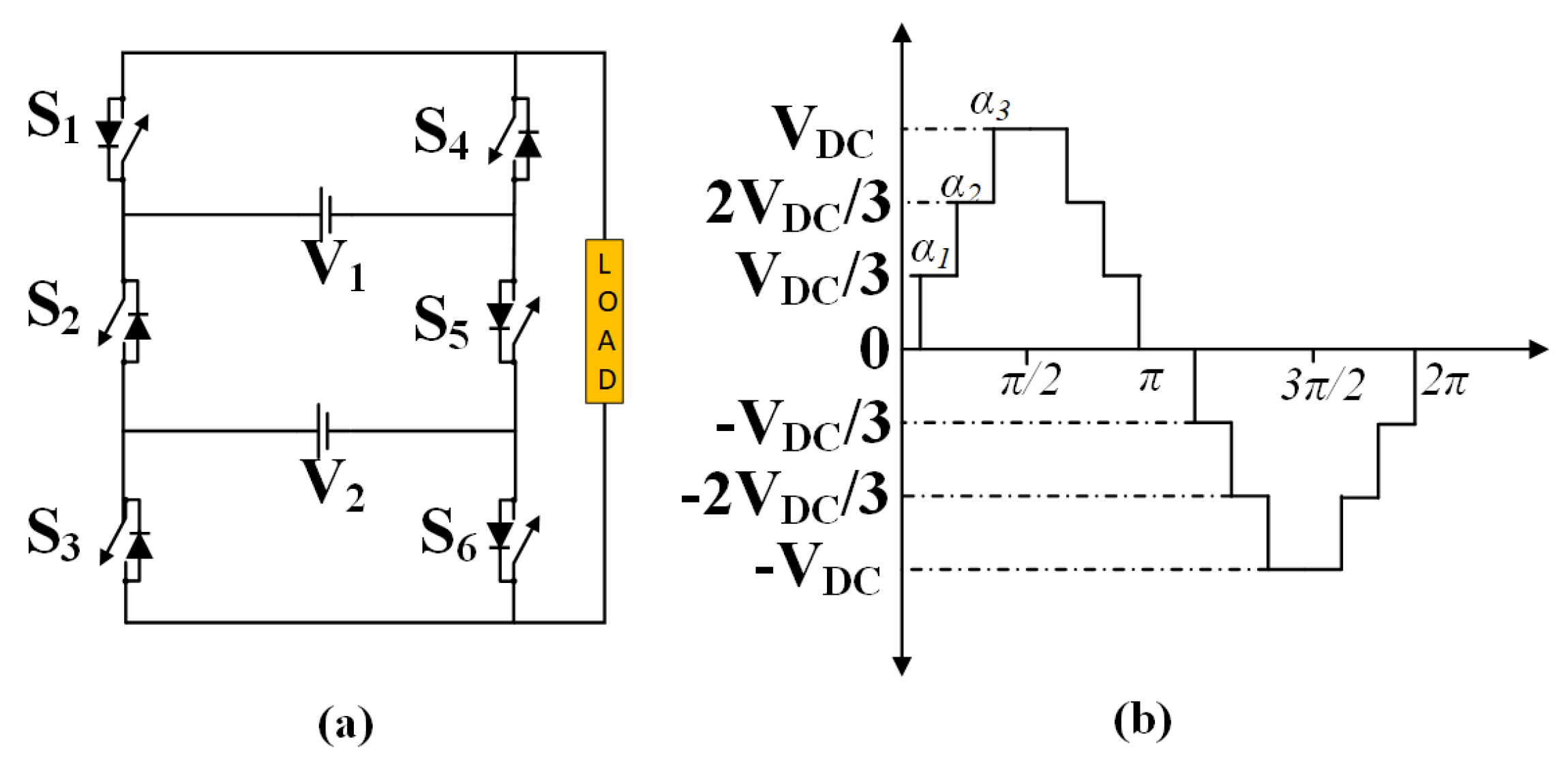
3.1. Seven-Level Modified Packed U-Cell Inverter Topology

The modified seven-level PUC (MPUC7) is a highly efficient topology designed to achieve fine-grained voltage output levels using a single primary DC source and an auxiliary DC source. In this configuration, the auxiliary DC source is maintained at one-third of the primary source’s voltage as shown in Figure 2a. Using six switching devices and these two sources, the inverter can generate seven distinct voltage levels: V 1 , 2 V 1 3 , V 1 3 , 0 , V 1 3 , 2 V 1 3 , and V 1 , as shown in Figure 2b.
This arrangement significantly reduces Total Harmonic Distortion (THD) by providing finer voltage steps, thereby ensuring better waveform quality. The compact design, leveraging fewer switches and only two DC sources, makes this inverter cost-effective and suitable for applications with space constraints. Additionally, the auxiliary DC source simplifies regulation since it does not require the complex control mechanisms typical for capacitors. However, maintaining the auxiliary source consistently at one-third of the primary source voltage is critical to ensure proper operation, and this dependency can slightly increase the system cost. The seven-level PUC inverter is particularly suitable for grid-tied renewable energy systems, distributed generation, and motor drives where high power quality and low THD are crucial.
Table 2 illustrates the switching states for an MPUC7 inverter, highlighting the behavior of switches S 1 , S 2 , and S 3 and their corresponding output voltage levels V a b . Each switching combination results in distinct voltage levels, ranging from V 1 to V 1 , including intermediate levels such as V 1 V 2 , V 2 , and V 2 V 1 . The table emphasizes the role of these switching states in generating a multilevel output voltage waveform, which is crucial for achieving enhanced power quality in various applications.

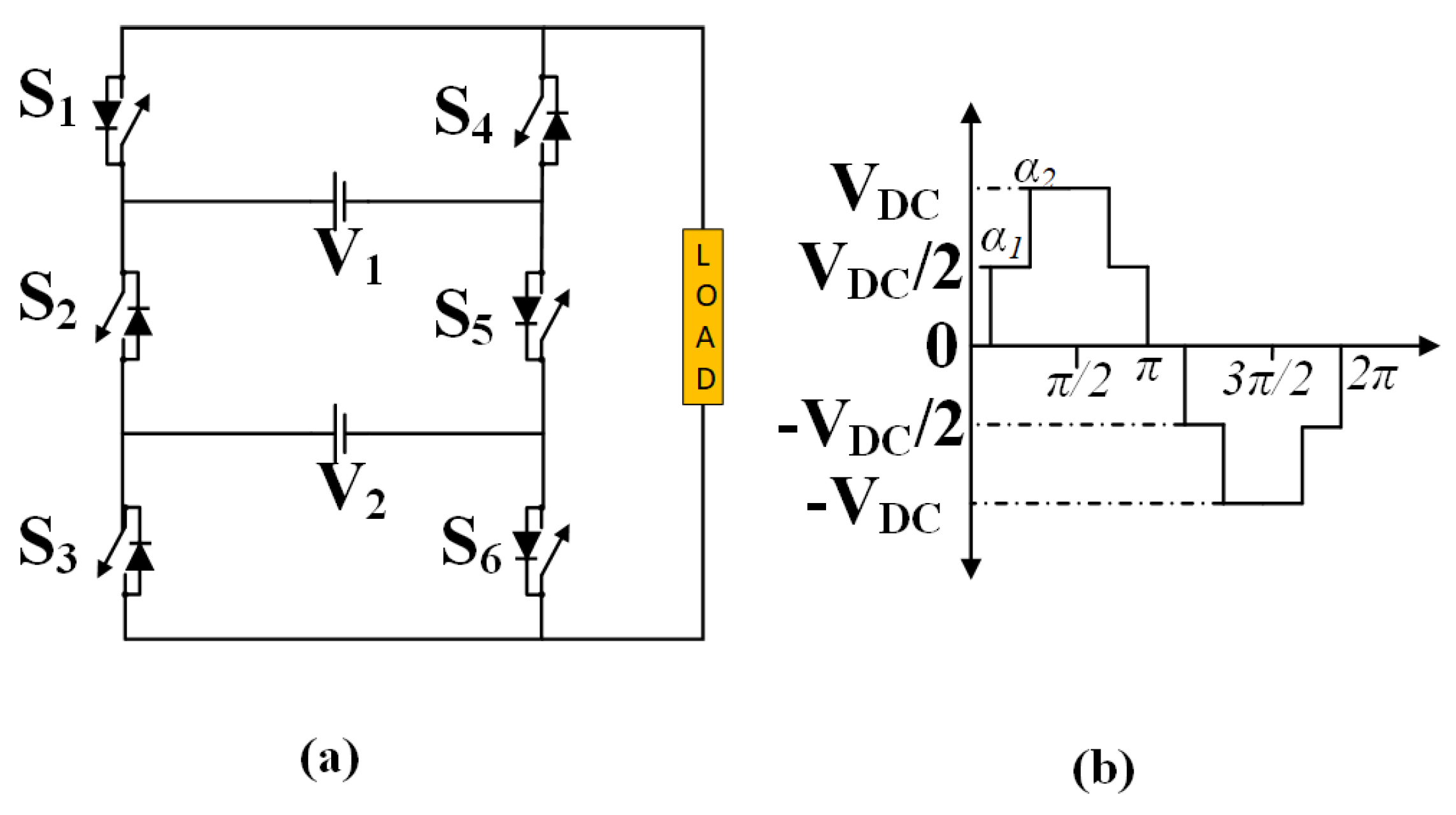
3.2. Five-Level Modified Packed U-Cell Inverter Topology

The modified five-level PUC (MPUC5), on the other hand, is a simpler and cost-effective variation of the seven-level topology. It employs a single primary DC source and an auxiliary DC source maintained at half the primary source’s voltage, as shown in Figure 3a. Using six switching devices, this configuration generates five voltage levels: V 1 , V 1 2 , 0 , V 1 2 , and V 1 , as shown in Figure 3b.
While it sacrifices the number of output voltage levels compared to the seven-level topology, this simplification results in a less complex control scheme, making it easier to implement and manage. The design is cost-effective and reduces computational overhead while still leveraging the auxiliary DC source to enhance harmonic suppression relative to traditional two-level inverters. However, the reduced number of voltage levels results in higher THD, necessitating additional filtering in some cases. Proper synchronization between the primary and auxiliary sources is essential to avoid voltage imbalances that could impact performance. The five-level PUC inverter is most commonly used in standalone renewable energy systems, low-power industrial applications, and scenarios where simplicity and cost-effectiveness are prioritized.
Table 3 presents the switching states for an MPUC5 inverter, detailing the configurations of switches S 1 , S 2 , and S 3 along with their corresponding output voltage levels V a b . The inverter generates five distinct voltage levels: V 1 , V 2 , 0, V 2 , and V 1 . These states are crucial for defining the operation of the inverter to produce a multilevel output voltage waveform, reducing harmonic distortion and improving power quality.

4. Problem Formulation for Harmonic Mitigation

For simplicity, harmonic mitigation for MPUC7 is discussed in this section. In similar fashion, the formulation of MPUC5 can be achieved [14,21]. As shown in Figure 2b, the output voltage of the seven-level MPUC will have three positive, three negative, and one zero levels. Thus, for level 7 of the MPUC, the output voltage can be written as
V ( t ) = V DC i = 1 3 u ( t α i ) i = 1 3 u t ( π α i ) i = 1 3 u t ( π + α i ) + i = 1 3 u t ( 2 π + α i )
The output voltage waveform of a multilevel inverter can be represented as a Fourier series due to its periodic, symmetric waveform. For a waveform with quarter-wave symmetry, only odd harmonics are present, and it can be expressed as follows:
V ( t ) = n = 1 , 3 , 5 , V n sin ( n ω t )
where V n is the amplitude of the n-th harmonic component and ω is the fundamental angular frequency.
For an inverter with three switching angles α 1 , α 2 , and α 3 , the harmonic components of the output voltage V ( t ) can be written as follows:
V n = 4 V D C π k = 1 3 cos ( n α k )
where V D C is the DC source voltage, n represents the harmonic order (e.g., 1, 3, 5, etc.), and α k gives the switching angles, with 0 < α 1 < α 2 < α 3 < π 2 .

4.1. Objective of Harmonic Mitigation

The primary objective of harmonic mitigation is to determine the switching angles α 1 , α 2 , and α 3 such that
  • The fundamental component V 1 is maintained at a specified reference value V r e f ,
  • The 3rd, 5th, 7th, 9th, and 11th harmonics are mitigated.

4.2. Formulating the Harmonic Equations

The harmonic equations for selective harmonic mitigation (SHM) can be formulated as follows:
  • Fundamental Component Equation:
    V 1 = 4 V D C π k = 1 3 cos ( α k ) = m . V D C
    Rearranging to express the relationship in terms of the modulation index m,
    k = 1 3 cos ( α k ) = π m 4
  • Harmonic Component Equations for Mitigation: To minimize the 3rd, 5th, 7th, 9th, and 11th harmonics, we set their components to zero:
    V 3 = 4 V D C π ( cos ( 3 α 1 ) + cos ( 3 α 2 ) + cos ( 3 α 3 ) ) = 0
    V 5 = 4 V D C π ( cos ( 5 α 1 ) + cos ( 5 α 2 ) + cos ( 5 α 3 ) ) = 0
    V 7 = 4 V D C π ( cos ( 7 α 1 ) + cos ( 7 α 2 ) + cos ( 7 α 3 ) ) = 0
    V 9 = 4 V D C π ( cos ( 9 α 1 ) + cos ( 9 α 2 ) + cos ( 9 α 3 ) ) = 0
    V 11 = 4 V D C π ( cos ( 11 α 1 ) + cos ( 11 α 2 ) + cos ( 11 α 3 ) ) = 0
The nonlinear system formed by Equations (4)–(10) must be solved in order to determine the ideal switching angles α 1 , α 2 , and α 3 that produce the required harmonic profile.

4.3. Defining the Cost Function for Harmonic Mitigation

Reducing the amplitudes of the chosen harmonics and minimizing the fundamental component’s deviation from its reference are the goals of the cost function F for harmonic mitigation. It can be described as follows:
F ( α 1 , α 2 , α 3 ) = V 1 V r e f + w 3 | V 3 | + w 5 | V 5 | + w 7 | V 7 | + w 9 | V 9 | + w 11 | V 11 |
where:
  • V 1 , V 3 , V 5 , V 7 , V 9 , and V 11 are the amplitudes of the fundamental, 3rd, 5th, 7th, 9th, and 11th harmonics, respectively,
  • w 3 , w 5 , w 7 , w 9 , and w 11 are weighting factors that determine the importance of each harmonic in the cost function.
Reducing F ( α 1 , α 2 , α 3 ) is the goal in order to obtain the fundamental reference value and eliminate undesired harmonics.

5. Proposed Methodology

Optimization techniques like the GA and PSO are effective for reducing THD but have limitations, such as that the GA converges slowly and can become stuck in local optima, while PSO often converges prematurely, missing better solutions [18]. Techniques like SA and DE require extensive parameter tuning, making them time-intensive. To address these issues, the hybrid GA-PSO combines GA’s wide exploration with PSO’s efficient fine-tuning, achieving faster and more reliable convergence. In this section, the proposed hybrid GA-PSO is designed and implemented to find out the optimal angles for both MPUC7 and MPUC5 inverters in order to reduce the THD.

5.1. Optimization Problem for Harmonic Elimination

  • Objective Function
The objective function F ( α ) can be defined as quantifying the error in satisfying the harmonic equations:
F ( α ) = k K f k ( α ) 2
where:=
  • K = { 1 , 3 , 5 , 7 , 9 , 11 } are the harmonic orders to consider.
  • f 1 ( α ) corresponds to the fundamental component equation.
  • f k ( α ) for k > 1 corresponds to the harmonic elimination equations.

5.1.1. Constraints

The following constraints are incorporated into the optimization problem:
  • Inequality Constraints:
    0 < α 1 < α 2 < < α n < 90
  • Modulation Index Constraint:
    0 < M 1

5.1.2. Penalty Function Approach

Now, adding penalty terms to the objective function for constraint violations, we obtain the following:
F total ( α ) = F ( α ) + P ( α )
where P ( α ) is the penalty function.

5.2. Algorithm Steps for SHM Using GA-PSO

5.2.1. Step 1: Initialize Population

(a)
The population size N is defined.
(b)
The initial positions α i for N particles within the constraints can be generated as follows:
α i , j = α i 1 , j + δ j
where δ j is a small random increment ensuring constraints are met.
(c)
Finally, the velocities v i are initialized to zero or small random values.

5.2.2. Step 2: Evaluate Fitness

For each particle i,
(a)
Calculation of f k ( α i ) for k K is carried out.
(b)
Then, the objective function is computed:
F total ( α i ) = k K f k ( α i ) 2
(c)
Then, the personal best position p i = α i is stored if F total ( α i ) improves the current best.
(b)
Finally, the global best position g is updated if F total ( α i ) is better than the current global best.

5.2.3. Step 3: Apply Genetic Algorithm Operators

(a)
Selection: The tournament selection is used to choose pairs of particles based on fitness.
(b)
Crossover: We applied single-point crossover at a random point c:
Offspring 1 : α 1 , 1 , , α 1 , c , α 2 , c + 1 , , α 2 , n
Offspring 2 : α 2 , 1 , , α 2 , c , α 1 , c + 1 , , α 1 , n
(c)
Mutation: Then, a randomly selected gene α i , j is mutated:
α i , j = α i , j + Δ
Mutation introduces diversity into the population by modifying a randomly selected gene α i , j . The parameter Δ represents the magnitude of change applied during mutation and is randomly chosen from the range [ 0.01 , 0.05 ] times the modulation index. This ensures that the mutation is significant enough to escape local optima but not so large as to violate constraints. The new value of α i , j is calculated as α i , j = α i , j + Δ , where Δ can be positive or negative. To ensure feasibility, the mutated α i , j is checked to remain within the constraint bounds 0 < α 1 < α 2 < < α n < 90 .

5.2.4. Step 4: Update Velocities and Positions (PSO Operators)

For each particle i,
(a)
Update Velocity:
v i , j ( t + 1 ) = w v i , j ( t ) + c 1 r 1 [ p i , j α i , j ( t ) ] + c 2 r 2 [ g j α i , j ( t ) ]
(b)
Update Position:
α i , j ( t + 1 ) = α i , j ( t ) + v i , j ( t + 1 )
(c)
It is important to ensure α i , j ( t + 1 ) remains within constraints:
α i , j ( t + 1 ) = α min if α i , j ( t + 1 ) < α min α max if α i , j ( t + 1 ) > α max
Enforce ordering:
α i , 1 < α i , 2 < < α i , n

5.2.5. Step 5: Update Personal and Global Bests

For each particle i, the following steps need to be performed:
(a)
Evaluating fitness F total ( α i ) .
(b)
Updating the personal best p i if F total ( α i ) improves the current personal best.
(c)
Updating the global best g if F total ( α i ) improves the current global best.

5.2.6. Step 6: Termination Criteria

(a)
Stopping after a predefined number of iterations.
(b)
Stopping if the change in global best fitness is below a small threshold for consecutive iterations.
(c)
Stopping if F total ( g ) is less than a predefined acceptable error.

5.2.7. Step 7: Output Results

(a)
Thus, the optimal switching angles α * = g are obtained.
(b)
Just to make sure, the optimal switching angles need to be verified:
f k ( α * ) 0 for k K

5.3. Hybrid GA-PSO Algorithm Design

The hybrid Genetic Algorithm–Particle Swarm Optimization (GA-PSO) algorithm for Selective Harmonic Mitigation (SHM) is designed to determine optimal switching angles for eliminating specific harmonics in a multilevel inverter while maintaining the desired fundamental voltage. This implementation begins with defining the optimization problem, including an objective function, constraints, and a penalty approach to handle constraint violations as shown in Figure 4. The objective function evaluates the sum of squared errors for harmonic elimination equations, with penalties added for constraint violations to ensure feasibility. Constraints ensure the switching angles are in ascending order, within defined bounds, and meet the modulation index requirement.
The population initialization involves generating random positions for particles (switching angles) within the constraint bounds and setting initial velocities to small random values. Each particle represents a potential solution to the harmonic elimination problem. The fitness of each particle is evaluated using the objective function, and personal and global best positions are updated based on their fitness. The personal best is the best solution found by a particle so far, while the global best is the best solution across the entire population.
The genetic algorithm operators include selection, crossover, and mutation. Selection is implemented through tournament selection, where pairs of particles are chosen based on fitness. Crossover exchanges genes (switching angles) between selected pairs at a random crossover point, creating offspring solutions. Mutation introduces random variations in the angles of selected particles to explore the solution space further. Both crossover and mutation maintain the constraints to ensure valid solutions.
The particle swarm optimization operators update the velocity and position of each particle. The velocity update uses the current velocity, the difference between the particle’s position and its personal best, and the difference between the particle’s position and the global best. The position update adds the updated velocity to the particle’s current position. Constraint enforcement ensures the updated positions remain valid, with corrections applied if necessary.
The position of personal and global best positions is updated at every iteration based on the fitness that has just been evaluated. Possible termination criteria for this algorithm can be a maximum number of iterations, convergence-minimum change in global best fitness over iteration, or an acceptable value of fitness. Once the algorithm has been terminated, it produces an optimal set of switching angles with its corresponding harmonic analysis. These results are checked in order to confirm harmonic elimination and modulation index requirements.
This novel hybrid GA-PSO technique uses the global exploration capability of the genetic algorithm and the local exploitation efficiency of particle swarm optimization. It thereby makes this algorithm robust and guarantees efficient optimization in solving the SHM problem in multilevel inverters. The results of this algorithm give minimum harmonics, optimum switching angles, and maintain fundamental voltage; hence, the algorithm serves as a feasible solution for power quality improvement in inverter systems.

5.3.1. Hybrid GA-PSO Algorithm for MPUC7

The hybrid algorithm for MPUC7 inverter optimizes three switching angles for minimum THD at a desired modulation index. With this hybrid approach, strengths are combined from the global exploration of the genetic algorithm and the local fine-tuned convergence of Particle Swarm Optimization. This presents an effective and efficient optimization of the angles in Python, implemented in VS Code. Figure 5 shows THD across various modulation indices and switching angles. It is observed that the hybrid algorithm correctly finds the optimal configuration. The three switching angles provide finer control for the output waveform to meet power quality requirements with the least harmonic content. In Figure 5, the 3D plots better relate the modulation index with the optimized angles to realize the resulting THD values.

5.3.2. Hybrid GA-PSO Algorithm for MPUC5

In the case of the MPUC5 inverter, the hybrid GA-PSO algorithm will seek the optimization of two switching angles for a minimum value of THD and desired modulation index. Because there are only two angles to optimize, the methodology is less computational and remarkably improves harmonic suppression. The Python implementation using VS Code is the same as for MPUC7; results are shown in Figure 6. The 3D plots show the relation between THD, modulation index, and the optimized angles. This hybrid algorithm has very good robustness to balance both THD minimization and modulation index requirements by meeting operational constraints on an inverter. The results highlight how two-angle optimization is quite suitable for simpler topologies like MPUC5, where the needs for computational efficiency and harmonic performance are of major importance.

6. Results and Discussion

Results obtained for both the MPUC7 and MPUC5 inverters are analyzed in two aspects: simulation through MATLAB/Simulink and real-time simulation using the OP5700 platform. The OP5700 platform enables high-fidelity emulation of hardware behavior by interfacing the digital model of the inverter with real-world loads and conditions. These results will show the performance of the inverters for different load conditions, such as fixed resistive load and variable RL load. These results confirm the efficiency and capability of the proposed hybrid GA-PSO algorithm in choosing an appropriate switching angle and the stability and reliability of the inverter outputs under both simulation and real-time conditions. The focus of this study is to propose and validate a novel hybrid GA-PSO algorithm for optimal switching angle determination aimed at achieving harmonic mitigation in modified packed U-cell (PUC) inverters. The algorithm’s ability to achieve low Total Harmonic Distortion (THD) and maintain waveform stability is demonstrated using linear loads, such as resistive (R) and resistive–inductive (RL) loads. These loads were chosen as a baseline to provide a controlled environment for isolating the effects of the optimization algorithm, ensuring a clear assessment of harmonic suppression and waveform stability. Linear RL loads are highly relevant to practical applications like motors, transformers, and grid-connected systems, making this scenario both insightful and industry-relevant. Future work will expand the scope to include nonlinear and dynamic loads to further validate the algorithm’s adaptability and robustness in broader real-world scenarios.

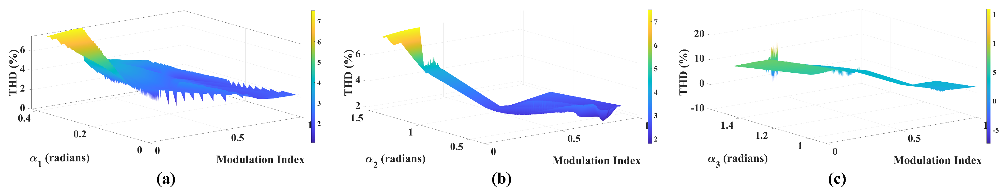
6.1. Simulation Results

The voltage and current waveforms for both the MPUC7 and MPUC5 inverters were obtained by using the MATLAB/Simulink simulation software; the simulation parameters used are tabulated in Table 4. For the MPUC7 inverter, the simulation was performed under four load conditions: a fixed resistive load of R = 40 Ω , a fixed RL load with R = 40 Ω and L = 80 mH , a varying resistive load transitioning from R = 40 Ω to R = 50 Ω , and a varying RL load transitioning from R = 40 Ω , L = 80 mH to R = 40 Ω , L = 80 mH . As observed in Figure 7, the voltage and current waveforms remained stable across all conditions. The waveform quality under RL loads showcased the inverter’s ability to handle reactive components effectively, ensuring consistent voltage and current outputs with minimal distortion. Similarly, for the MPUC5 inverter, the results in Figure 8 displayed stable and well-regulated waveforms under identical load conditions. The fewer switching angles in the MPUC5 inverter resulted in slightly higher Total Harmonic Distortion (THD) compared to the MPUC7, but the overall waveform integrity remained suitable for practical applications. These simulations validated the hybrid GA-PSO algorithm’s efficiency in determining optimal switching angles, ensuring low THD, and maintaining waveform stability across varying load conditions.
Figure 9 illustrates the voltage FFT (Fast Fourier Transform) analysis for the MPUC7 and MPUC5 inverters, providing insight into the harmonic content of their output waveforms. For the MPUC7 inverter, as shown in Figure 9a, the waveform is observed with a THD of 11.48%. The FFT analysis highlights the presence of lower-order harmonics, but the hybrid GA-PSO algorithm has successfully minimized their amplitudes, ensuring that the THD remains within acceptable limits for most power quality standards. This performance demonstrates the effectiveness of the optimized switching angles in controlling harmonic content while maintaining a high-quality output waveform.
In Figure 9b, the FFT analysis for the MPUC5 inverter shows a waveform is observed with a higher THD of 17.43%. The increased THD compared to the MPUC7 inverter is attributed to the reduced number of voltage levels and fewer switching angles available in the MPUC5 topology. Despite this limitation, the FFT results show that the major harmonics are still well managed, making the MPUC5 suitable for applications where slightly higher harmonic distortion can be tolerated. The comparative analysis between the two inverters emphasizes the advantage of having more voltage levels in reducing harmonic distortion and improving waveform quality.

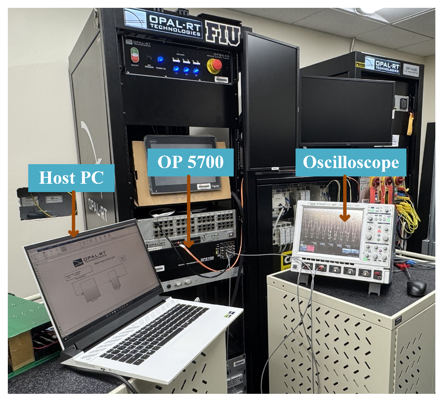
6.2. Real-Time Simulation Results

Digital Implementation

The hybrid GA-PSO algorithm was implemented and validated using a comprehensive digital framework combining software tools and real-time hardware platforms. The algorithm was developed using Python 3.13.0 and MATLAB 2023b leveraging their optimization toolboxes to solve the harmonic mitigation problem efficiently. MATLAB/Simulink was used to model the modified packed U-cell (PUC) inverters and simulate their performance under various operating conditions, with the hybrid GA-PSO algorithm integrated into the Simulink environment for real-time optimization of switching angles. For real-world applicability, the algorithm was validated using the OP5700 hardware-in-the-loop (HIL) platform, which provided high-fidelity emulation of inverter performance under practical load conditions. The workflow included initial algorithm coding and testing in Python, integration of optimized switching angles into MATLAB/Simulink models for harmonic analysis, and deployment on the OP5700 platform to evaluate robustness under varying load scenarios. The digital implementation demonstrated efficient convergence to optimal switching angles, reduced computational overhead, and consistent performance, as reflected in waveform quality and harmonic suppression metrics. This process validates the hybrid GA-PSO algorithm as a robust and scalable solution for real-time applications in harmonic mitigation.
Real-time simulation results were conducted on the OP5700 hardware-in-the-loop (HIL) platform to verify the inverter performance in real-world scenarios as shown in Figure 10. In Figure 11, the real-time implementation of the MPUC7 inverter is depicted under four load conditions. Figure 11a shows the output voltage and current waveforms under a fixed resistive load of R = 40 Ω . The voltage waveform exhibits a clear seven-level stepped structure, demonstrating the proper operation of the switching strategy. The current waveform remains nearly square, consistent with the characteristics of a resistive load. In Figure 11b, with a fixed RL load ( R = 40 Ω , L = 80 mH ), the current waveform becomes smoother and sinusoidal due to the inductive nature of the load, while the voltage retains its stepped profile. A visible phase shift occurs between V out and I out , reflecting the inductive behavior. Figure 11c illustrates the inverter’s performance under a varying resistive load as the resistance increases from ( R = 40 Ω 50 Ω ). Both the voltage and current waveforms remain stable, with the voltage maintaining its seven-level pattern and the current adjusting proportionally to the change in load. Figure 11d shows the waveforms under a varying RL load, where the load increases ( R = 40 Ω , R = 40 Ω , L = 80 mH ). As the inductance increases, the current waveform becomes smoother with an increased phase shift relative to the voltage waveform. The results confirm the inverter’s robustness and ability to adapt to changing load conditions while maintaining output quality.
Figure 12 presents the real-time implementation results for the MPUC5 inverter under the same load conditions. In Figure 12a, for a fixed resistive load ( R = 40 Ω ), the voltage waveform clearly displays a five-level stepped pattern, which is characteristic of the MPUC5 topology. The current waveform remains square, consistent with resistive load behavior. Figure 12b depicts the inverter’s operation under a fixed RL load ( R = 40 Ω , L = 80 mH ), where the current waveform becomes sinusoidal due to the inductance, and a phase shift occurs between V out and I out . Figure 12c shows the performance under a varying resistive load ( R = 40 Ω 50 Ω ), with both voltage and current waveforms remaining stable as the load increases. Finally, Figure 12d illustrates the waveforms under a varying RL load ( R = 40 Ω , R = 40 Ω , L = 80 mH ). The current waveform smooths further with increasing inductance, and a clear phase shift relative to the voltage waveform is observed. The results validate the MPUC5 inverter’s ability to handle varying load conditions while maintaining its output performance, though with fewer voltage levels compared to the MPUC7.
Figure 13 provides the FFT analysis of the output voltage for both the MPUC7 and MPUC5 inverters, demonstrating the harmonic suppression achieved by the proposed hybrid GA-PSO optimization technique. In Figure 13a, the FFT analysis for the MPUC7 inverter shows the dominant fundamental frequency at 60 Hz , with significantly reduced lower-order harmonics, such as the third, fifth, and seventh harmonics. The Total Harmonic Distortion (THD) is measured at 11.68%, confirming the inverter’s ability to achieve effective harmonic elimination. Figure 13b presents the FFT analysis for the MPUC5 inverter, where the fundamental frequency is also observed at 60 Hz , but the harmonic components are slightly more pronounced compared to MPUC7. The THD for MPUC5 is measured at 17.61%, which is higher due to the lower number of voltage levels. These results clearly demonstrate that the proposed hybrid GA-PSO algorithm effectively minimizes THD and mitigates harmonic distortions, with MPUC7 achieving superior performance owing to its higher voltage levels.
The discussion of results demonstrates the hybrid GA-PSO algorithm’s success in optimizing switching angles to minimize THD while maintaining stable voltage and current waveforms. Both simulation and real-time results validate the robustness and adaptability of the MPUC7 and MPUC5 inverters for grid-connected and standalone applications. Thus, their confirmation under widely ranging load conditions proves their suitability for renewable energy systems where the dynamics of the variation in load conditions are different. The hybrid optimization approach ensures the possibility for both inverters to achieve high power quality with minimum possible distortion, therefore being reliable for modern power systems.
In order to verify the efficiency of the proposed GA-PSO, we compare its performance with other algorithms such as the GA, DE, and GWO, as shown in Table 5. Results are depicted in Table 5 where the THD is minimized to 17.61% using the GA-PSO method in comparison to GWO (30.20%), DE (29.99%), and GA (27.26%). The third, fifth, and seventh harmonic components have also been minimized to 0.23%, 0.46%, and 0.87%, respectively, to further confirm the robustness of the hybrid GA-PSO approach for mitigation of harmonics.

6.3. Application

The proposed hybrid GA-PSO algorithm and modified packed U-cell (PUC) inverters offer significant potential across various applications. In renewable energy systems, the method is highly suitable for grid-connected and standalone setups, such as photovoltaic (PV) and wind energy systems, where achieving low Total Harmonic Distortion (THD) is critical for compliance with IEEE 519 standards and maintaining power quality. The compact design and efficiency of the modified PUC topology make it ideal for microgrid integration, where dynamic load conditions require robust harmonic mitigation and cost-effective solutions. Industrial applications, including motor drives and high-precision power electronics systems, can benefit from the algorithm’s ability to reduce harmonic losses and enhance waveform quality. Additionally, the approach is applicable to electric vehicle (EV) charging infrastructure, where harmonic suppression ensures grid stability and efficient charging. The scalability of the PUC topology enables its use in high-voltage and high-power applications, such as HVDC transmission systems. Furthermore, the proposed solution addresses harmonic pollution in distribution systems, improving grid stability and reducing losses. Its adaptability to dynamic conditions makes it a strong candidate for future smart grids, facilitating the integration of diverse Distributed Energy Resources (DERs) with advanced harmonic control.

7. Conclusions

This work proposes an effective harmonic mitigation method for modified packed U-cell inverters using a hybrid algorithm based on Genetic Algorithm–Particle Swarm Optimization techniques. The proposed technique effectively combines the exploratory diversity of genetic algorithms with the precise convergence efficiency of Particle Swarm Optimization as an effort to tune the optimal value of switching angles for reduced harmonic distortion, minimized voltage stress, and increased operational efficiency. The THD for the MPUC7 inverter presented a value of 11.68%, which is far below conventional approaches. Similarly, for the MPUC5 inverter, a THD of 17.61% was obtained, proving that the approach proposed here also applies to other topologies. The approach also worked effectively for a resistive load with R = 40 Ω and an inductive–resistive load with R = 40 Ω and L = 80 mH , where the voltage and current waveforms continued to remain stable across changing load conditions. Real-time tests on the hardware-in-the-loop platform OP5700 further reinforced these results, where the MPUC7 inverter maintained a THD within IEEE standards and presented high-quality waveforms across fixed and time-varying loads. It was also seen that the hybrid technique outperformed standalone GA and PSO techniques with faster convergence, low computational overhead, and with better harmonic suppression. These results indicate the appropriateness of the hybrid algorithm for modern power systems, especially when it comes to the integration of renewable energy sources and microgrids. It also proves to be suitable under dynamic load conditions and has the ability to ensure high power quality with practical and efficient multilevel inverter designs. Future research may apply this approach to the higher-level inverters and investigate the approach with adaptation possibilities in real-time control systems for further performance improvements in complex grid conditions. Comparative results, as shown in Table 5, validate the effectiveness of the proposed GA-PSO method for harmonic suppression performance improvement, which outperforms traditional algorithms like the GA, DE, and GWO. The proposed approach is thus very effective at reducing THD and optimizing harmonic performance for multilevel inverters. Future work will extend the work of this study to include nonlinear and time-varying loads, showcasing the hybrid GA-PSO algorithm’s adaptability to complex conditions such as harmonic interactions from rectifiers and variable-speed drives. Additionally, we aim to develop a full hardware prototype of the grid-tied modified PUC inverter, integrating the hybrid GA-PSO algorithm. This prototype will be optimized for field tests and validated under nonlinear and dynamic load conditions, with findings to be published in subsequent work.

Author Contributions

Conceptualization, H.I. and A.S.; methodology, H.I. and A.S.; software, H.I.; validation, H.I. and A.S.; formal analysis, A.S.; investigation, H.I. and A.S.; resources, H.I.; data curation, H.I.; writing—original draft preparation, H.I.; writing—review and editing, A.S.; visualization, H.I.; supervision, A.S.; project administration, A.S. All authors have read and agreed to the published version of the manuscript.

Funding

This research received no external funding.

Data Availability Statement

The original contributions presented in the study are included in the article; further inquiries can be directed to the corresponding author(s).

Conflicts of Interest

The authors declare no conflicts of interest.

Abbreviations

The following abbreviations are used in this manuscript:
CHBCascaded H-Bridge
DCDirect Current
DEDifferential Evolution
FCFlying Capacitor
FFTFast Fourier Transform
GAGenetic Algorithm
HILHardware-in-the-Loop
MLIMultilevel Inverter
MOOMulti-Objective Optimization
MPUC5Modified Five-Level Packed U-Cell Inverter
MPUC7Modified Seven-Level Packed U-Cell Inverter
NSGA-IINon-Dominated Sorting Genetic Algorithm-II
NPCNeutral Point Clamped
PSOParticle Swarm Optimization
PUCPacked U-Cell
RLResistive-Inductive
SASimulated Annealing
SHMSelective Harmonic Mitigation
THDTotal Harmonic Distortion

References

  1. Srinivasan, G.K.; Rivera, M.; Loganathan, V.; Ravikumar, D.; Mohan, B. Trends and challenges in multi-level inverter with reduced switches. Electronics 2021, 10, 368. [Google Scholar] [CrossRef]
  2. Bughneda, A.; Salem, M.; Richelli, A.; Ishak, D.; Alatai, S. Review of multilevel inverters for PV energy system applications. Energies 2021, 14, 1585. [Google Scholar] [CrossRef]
  3. Mehta, S.; Puri, V. A review of different multi-level inverter topologies for grid integration of solar photovoltaic system. Renew. Energy Focus 2022, 43, 263–276. [Google Scholar] [CrossRef]
  4. Ali Khan, M.Y.; Liu, H.; Yang, Z.; Yuan, X. A comprehensive review on grid connected photovoltaic inverters, their modulation techniques, and control strategies. Energies 2020, 13, 4185. [Google Scholar] [CrossRef]
  5. Villanueva, E.; Correa, P.; Rodríguez, J.; Pacas, M. Control of a single-phase cascaded H-bridge multilevel inverter for grid-connected photovoltaic systems. IEEE Trans. Ind. Electron. 2009, 56, 4399–4406. [Google Scholar] [CrossRef]
  6. Rana, R.A.; Patel, S.A.; Muthusamy, A.; Lee, C.W.; Kim, H.J. Review of multilevel voltage source inverter topologies and analysis of harmonics distortions in FC-MLI. Electronics 2019, 8, 1329. [Google Scholar] [CrossRef]
  7. Taghvaie, A.; Haque, M.E.; Saha, S.; Mahmud, M.A. A new step-up switched-capacitor voltage balancing converter for NPC multilevel inverter-based solar PV system. IEEE Access 2020, 8, 83940–83952. [Google Scholar] [CrossRef]
  8. Chenchireddy, K.; Jegathesan, V. A Review Paper on the Elimination of Low-Order Harmonics in Multilevel Inverters Using Different Modulation Techniques. In Inventive Communication and Computational Technologies: Proceedings of ICICCT 2020; Springer: Berlin/Heidelberg, Germany, 2021; pp. 961–971. [Google Scholar]
  9. Singhal, A.; Vu, T.L.; Du, W. Consensus control for coordinating grid-forming and grid-following inverters in microgrids. IEEE Trans. Smart Grid 2022, 13, 4123–4133. [Google Scholar] [CrossRef]
  10. Vairavasundaram, I.; Varadarajan, V.; Pavankumar, P.J.; Kanagavel, R.K.; Ravi, L.; Vairavasundaram, S. A review on small power rating PV inverter topologies and smart PV inverters. Electronics 2021, 10, 1296. [Google Scholar] [CrossRef]
  11. Iqbal, H.; Khalid, A.; Riggs, H.; Sarwat, A. Kalman Filter-Based Harmonic Distortion Mitigation Technique for Microgrid Applications. In Applications and Optimizations of Kalman Filter and Their Variants; IntechOpen: London, UK, 2024; Chapter 1. [Google Scholar]
  12. Poorfakhraei, A.; Narimani, M.; Emadi, A. A review of multilevel inverter topologies in electric vehicles: Current status and future trends. IEEE Open J. Power Electron. 2021, 2, 155–170. [Google Scholar] [CrossRef]
  13. Iqbal, H.; Tariq, M.; Sarfraz, M.; Anees, M.A.; Alhosaini, W.; Sarwar, A. Model predictive control of Packed U-Cell inverter for microgrid applications. Energy Rep. 2022, 8, 813–830. [Google Scholar] [CrossRef]
  14. Iqbal, H.; Tariq, M.; Sarfraz, M.; Sarwat, A.I.; Alhosaini, W.; Aldosari, O.; Aziz, A. Selective harmonic mitigation based two-scale frequency control of cascaded modified packed U-Cell inverters. Energy Rep. 2022, 8, 1009–1020. [Google Scholar] [CrossRef]
  15. IEEE Std 519-2022; IEEE Standard for Harmonic Control in Electric Power Systems. IEEE: Piscataway, NJ, USA, 2022; pp. 1–31. Available online: https://ieeexplore.ieee.org/document/9848440 (accessed on 14 November 2024).
  16. Duc, M.L.; Hlavaty, L.; Bilik, P.; Martinek, R. Harmonic mitigation using meta-heuristic optimization for shunt adaptive power filters: A review. Energies 2023, 16, 3998. [Google Scholar] [CrossRef]
  17. Eroğlu, H.; Cuce, E.; Cuce, P.M.; Gul, F.; Iskenderoğlu, A. Harmonic problems in renewable and sustainable energy systems: A comprehensive review. Sustain. Energy Technol. Assess. 2021, 48, 101566. [Google Scholar] [CrossRef]
  18. Memon, M.A.; Siddique, M.D.; Mekhilef, S.; Mubin, M. Asynchronous particle swarm optimization-genetic algorithm (APSO-GA) based selective harmonic elimination in a cascaded H-bridge multilevel inverter. IEEE Trans. Ind. Electron. 2021, 69, 1477–1487. [Google Scholar] [CrossRef]
  19. Adak, S. Harmonics mitigation of stand-alone photovoltaic system using LC passive filter. J. Electr. Eng. Technol. 2021, 16, 2389–2396. [Google Scholar] [CrossRef]
  20. Raman, R.; Sadhu, P.K.; Kumar, R.; Rangarajan, S.S.; Subramaniam, U.; Collins, E.R.; Senjyu, T. Feasible Evaluation and Implementation of Shunt Active Filter for Harmonic Mitigation in Induction Heating System. Electronics 2022, 11, 3464. [Google Scholar] [CrossRef]
  21. Iqbal, H.; Tufail, S.; Tariq, M.; Sarwat, A.I.; Sarwar, A. GA-based Integrated SHM-NLC Control for a Single Sourced Switched Capacitor Multi-Level Inverter with Boosting Capability for Microgrid. In Proceedings of the 2023 IEEE International Conference on Energy Technologies for Future Grids (ETFG), Wollongong, Australia, 3–6 December 2023; pp. 1–6. [Google Scholar]
  22. Gad, A.G. Particle swarm optimization algorithm and its applications: A systematic review. Arch. Comput. Methods Eng. 2022, 29, 2531–2561. [Google Scholar] [CrossRef]
  23. Fontes, D.B.; Homayouni, S.M.; Gonçalves, J.F. A hybrid particle swarm optimization and simulated annealing algorithm for the job shop scheduling problem with transport resources. Eur. J. Oper. Res. 2023, 306, 1140–1157. [Google Scholar] [CrossRef]
  24. Li, G.; Wang, W.; Zhang, W.; Wang, Z.; Tu, H.; You, W. Grid search based multi-population particle swarm optimization algorithm for multimodal multi-objective optimization. Swarm Evol. Comput. 2021, 62, 100843. [Google Scholar] [CrossRef]
  25. Deng, W.; Shang, S.; Cai, X.; Zhao, H.; Song, Y.; Xu, J. An improved differential evolution algorithm and its application in optimization problem. Soft Comput. 2021, 25, 5277–5298. [Google Scholar] [CrossRef]
  26. Guilmeau, T.; Chouzenoux, E.; Elvira, V. Simulated annealing: A review and a new scheme. In Proceedings of the 2021 IEEE Statistical Signal Processing Workshop (SSP), Rio de Janeiro, Brazil, 11–14 July 2021; pp. 101–105. [Google Scholar]
  27. Sharma, S.; Kumar, V. A comprehensive review on multi-objective optimization techniques: Past, present and future. Arch. Comput. Methods Eng. 2022, 29, 5605–5633. [Google Scholar] [CrossRef]
  28. Abdel-Basset, M.; Mohamed, R.; Mirjalili, S. A novel whale optimization algorithm integrated with Nelder–Mead simplex for multi-objective optimization problems. Knowl.-Based Syst. 2021, 212, 106619. [Google Scholar] [CrossRef]
Figure 1. Single U-cell.
Energies 18 00124 g001
Figure 2. (a) Seven−level PUC inverter. (b) Seven-level synthetic output voltage waveform.
Energies 18 00124 g002
Figure 3. (a) Five−level modified PUC inverter. (b) Five-level synthetic output voltage waveform.
Energies 18 00124 g003
Figure 4. Proposed algorithm working flowchart.
Energies 18 00124 g004
Figure 5. Variation in corresponding THD and modulation index for MPUC7 with different switching angles (a) α 1 ; (b) α 2 ; (c) α 3 .
Energies 18 00124 g005
Figure 6. Variation in corresponding THD and modulation index for MPUC5 with different switching angles (a) α 1 ; (b) α 2 .
Energies 18 00124 g006
Figure 7. Simulated in Matlab/Simulink voltage and current waveform for MPUC7 under (a) fixed 40 Ω R−load, (b) fixed ( R = 40 Ω , L = 80 mH ) RL−load, (c) varying load from ( R = 40 Ω ) R−load to ( R = 50 Ω ) RL−load, and (d) varying R−load from ( R = 40 Ω ) to ( R = 40 Ω , L = 80 mH ) .
Energies 18 00124 g007
Figure 8. Simulated in Matlab/Simulink voltage and current waveform for MPUC5 under (a) fixed 40 Ω R−load, (b) fixed ( R = 40 Ω , L = 80 mH ) RL−load, (c) varying load from ( R = 40 Ω ) R−load to ( R = 50 Ω ) RL−load, and (d) varying R−load from ( R = 40 Ω ) to ( R = 40 Ω , L = 80 mH ) .
Energies 18 00124 g008
Figure 9. Voltage FFT analysis for (a) MPUC7 and (b) MPUC5.
Energies 18 00124 g009
Figure 10. Real−time simulation setup using Opal-rt OP5700.
Energies 18 00124 g010
Figure 11. Real−time implementation for MPUC7 using OP5700 under (a) fixed 40 Ω R-load, (b) fixed ( R = 40 Ω , L = 80 mH ) RL−load, (c) varying R load from 40 Ω to 50 Ω , and (d) varying load from 40 Ω R-load to ( R = 40 Ω , L = 80 mH ) RL−load.
Energies 18 00124 g011
Figure 12. Real−time implementation for MPUC5 using OP5700 under (a) fixed 40 Ω R−load, (b) fixed ( R = 40 Ω , L = 80 mH ) RL-load, (c) varying R load from 40 Ω to 50 Ω , and (d) varying load from 40 Ω R-load to ( R = 40 Ω , L = 80 mH ) RL−load.
Energies 18 00124 g012
Figure 13. Voltage FFT analysis using real-time simulation for (a) MPUC7 and (b) MPUC5.
Energies 18 00124 g013
Table 1. Comparison with Other Existing MLIs.
ComponentsNPC5FLC5CHB5PUC5PUC7
Switches88866
Capacitor47211
Clamping Diode60000
Control ComplexityVery HighVery HighLowLowHigh
Table 2. Switching states for MPUC7 inverters.
Switching StatesS1S2S3Vab
1100 V 1
2101 V 1 V 2
3110 V 2
41110
50000
6001 V 2
7010 V 2 V 1
8011 V 1
Table 3. Switching states for MPUC5 inverters.
Switching StatesS1S2S3Vab
1100 V 1
2101 V 2
31110
40000
5001 V 2
6011 V 1
Table 4. Simulation parameters.
ParametersValues
V 1 300 V
V 2 100 V (for MPUC7), 150 V for (MPUC5)
Capacitors2200 μF, 200 V; 2200 μF, 200 V
Resistance at load40 Ω , 50 Ω
Inductance at load80 mH
Frequency60 Hz
Table 5. Comparison with other optimization techniques.
Optimization AlgorithmThird (%)Fifth (%)Seventh (%)THD (%)
GWO1.3325.291.5030.20
DE1.9316.0618.3629.99
GA0.5722.671.4527.26
GA-PSO (This work)0.230.460.8717.61
Disclaimer/Publisher’s Note: The statements, opinions and data contained in all publications are solely those of the individual author(s) and contributor(s) and not of MDPI and/or the editor(s). MDPI and/or the editor(s) disclaim responsibility for any injury to people or property resulting from any ideas, methods, instructions or products referred to in the content.

