Abstract
This paper presents the results of an optimization analysis of two types of thermal fluid channels. The selected geometries were evaluated according to the criterion of the Entropy Generation Minimization method as suggested by Adrian Bejan, with reference to a smooth pipe of the same diameter. The aim of this research was to assess the effectiveness of two channels that intensify heat transfer in different ways: with an insert (disrupting the flow in the pipe core) and with internal fins (disrupting the flow at the pipe wall), and to compare the results using the same criterion: the EGM method. The tested insert consisted of spaced streamline-shaped flow turbulizing the elements fixed in the axis of the pipe and spaced at equal distances from each other. The second channel was formed by making a right-angled triangle (rib profile) on the deformation of the pipe wall perimeter. Using computer modeling, the effect of the two geometric parameters of the above-mentioned channels on the flux of entropy generated was studied. These are (a) the diameter of the disturbing element (“droplet”) and the distance between these elements for a channel with a turbulent insert, and (b) the height of the rib and the longitudinal distance between them for a finned channel. The novelty resulting from the research is the discovery that the turbulization of the flow in the pipe wall boundary layer generates significantly less irreversible entropy than the disturbance of the flow in the pipe axis by the insert.
1. Introduction
The intensification of heat transfer in heat exchanger channels is always correlated with an increase in the flow resistance. This fact entails an increase in the energy used for pumping the fluid, while reducing the temperature difference due to the turbulization of the flow. The thermodynamic optimization of such channels is aimed at ensuring such thermal fluid parameters for a given geometry that the total efficiency of such a device is maximized (or as high as possible). This occurs when the sum of generated entropy arising from irreversible processes reaches a minimum. Bejan [1] was one of the first to give a theoretical basis for calculating the generated entropy for a smooth pipe and called the optimization method itself the EGM (Entropy Generation Minimization) method. Also, for geometries other than smooth pipe, it is possible to derive the corresponding analytical relationships, but the correlation between flow (friction coefficient f) and thermal (Nusselt number Nu) parameters must be known.
For many new channel geometries, these relationships are not known. Therefore, experimental measurements or numerical simulations are carried out to know the thermal-flow characteristics f(Re) and Nu(Re).
Well-made numerical simulations have the advantage over experiments as, besides the average values of velocity, temperature, and heat transfer coefficient, their vector or scalar fields across the channel are also known. These data can be directly used for EGM optimization analysis.
The aim of this paper is to present the findings gained from computer simulation for two types of channels: (i) a pipe with a drop-shaped insert and (ii) a pipe with ribbed protrusions on the wall. These channels were chosen because of their slightly different method of flow turbulence. In the first channel, the insert is placed in the axis of the pipe and causes a disturbance of the flow in the turbulent core. The fluid stream bypasses the elements of the insert by locally increasing the velocity at the wall. In the second channel, the flow-disturbing elements are transverse asymmetrical ribs, which cause an increase in the heat transfer surface and locally break the fluid boundary layer on the wall. This entails a significant increase in turbulence in this area of the channel, while having little effect on the turbulent core.
In the available literature, there are virtually no studies comparing the two heat transfer intensification methods in terms of thermodynamic optimization (EGM methods). However, one can find many studies for other heat transfer intensification inserts. For example, Tandiroglu [2] studied entropy generation in a pipe with baffle inserts in different geometric arrangements for turbulent flow. Yakut et al. [3,4] analyzed the effect of conical-ring turbulators on heat transfer, pressure drop, flow-induced vibration, and vortices. In addition, the coefficient of thermal efficiency at constant pumping power and entropy generation were also assessed. Under the entropy generation criterion, conical ring turbulators demonstrated advantages as energy-saving devices, especially at low Reynolds numbers, as they generated a low pressure drop in the studied range of Re numbers. Sahiti et al. [5] investigated a double-pipe pin fin heat exchanger. They analyzed the value of generated entropy as a function of Re number and showed that, for all the channel lengths studied, it is possible to find the optimal range of Re number in which the entropy minimum is generated. Kurtba et. al. [6] studied yet another turbulizing device: propeller-type swirl generators, in which the variable geometric parameters were the longitudinal distance between the propeller blades and the angle of inclination of those blades. Their studies indicate that the Nusselt number and, thus, the efficiency of a heat exchanger with installed turbulators increases up to 3.6 and 5.09 times compared to a smooth tube, and the increase in heat transfer results in an increase in the entropy generation factor of about 2.8 times. Other researchers, such as Ogulata [7], Vargas [8], and Iyengar [9], have studied various geometric configurations of internally finned heat exchanger channels in terms of generating minimum entropy in the heat transfer process and flow resistance, as well as their thermodynamic optimization. Jasinski, in [10], presented a numerical investigation of the influence of the angle of helical micro-ribbing in a pipe on entropy generation. The analysis showed that the least amount of entropy is generated in a pipe with a ribbing angle of 70°. Sakkay et al. [11] investigated a rectangular microchannel heat sink with inserted pillars to improve thermo-hydraulic performance for different geometric configurations of the pillars used. In this study, they analyzed the impact of both pillar position and their diameter. The authors demonstrated that increasing the number of pillars improves heat transfer by expanding the area, mixing fluids, and increasing velocity, but also increases entropy generation due to frictional resistance during fluid flow. At the same time, entropy generation from heat transfer decreases, where its minimum is reached at a pillar number of 50 and at Re = 740. Al-Daamee et al. [12] studied the heat flow characteristics and total entropy generation during laminar flow in a straight, triangular, and sinusoidal channel. They reported the highest values of entropy generation, but also heat transfer intensification for the sinusoidal duct, slightly smaller for the triangular duct and the lowest for the straight duct. Zhu Q. et al. [13] numerically studied microchannels with drop-shaped cavities in the channel walls and with rib columns of different shapes placed in the center of such a cavity. Among other things, they studied the impact of the shape and position of the rib columns on the thermal and flow characteristics of the microchannels. The authors reported that a microchannel with cavities alone without rib columns had the highest entropy production during heat transfer, while a channel with rectangular rib columns had the lowest. Entropy production in such a channel is lower by about 13–20% compared to a microchannel with empty cavities.
2. Tested Geometries
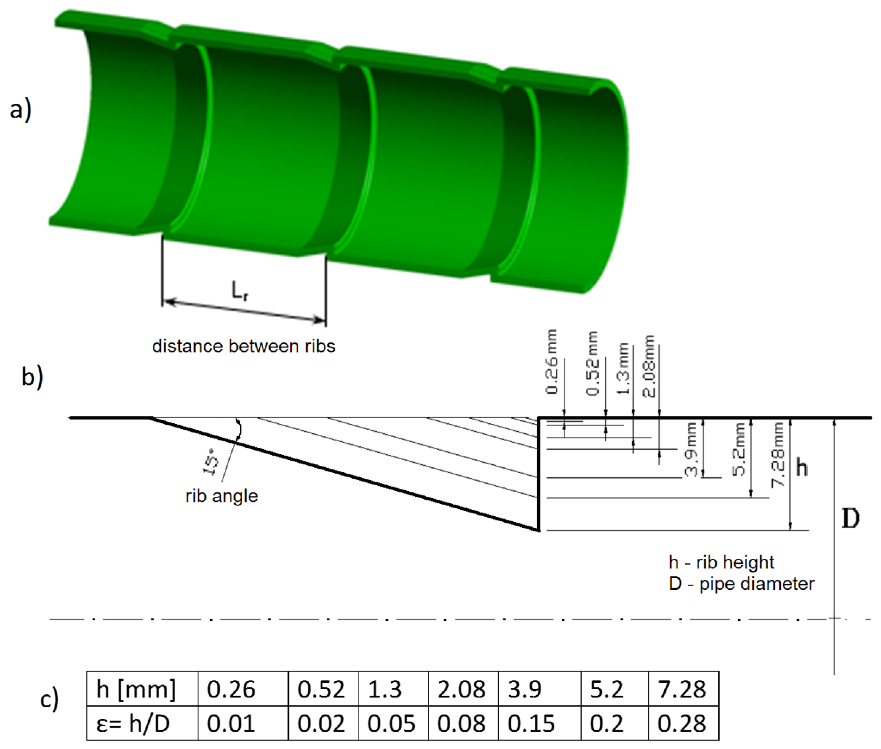
Figure 1 shows the first of the geometries studied: a pipe with transverse, asymmetrical ribs, which were created by deforming the wall. A wide range of rib dimensions was investigated numerically: 7 heights h with 7 different longitudinal distances Lr between them, resulting in 7 × 7 = 49 different rib configurations. Figure 1c shows the heights of the ribs studied and the corresponding dimensionless values, while the longitudinal distances are given in Table 1.
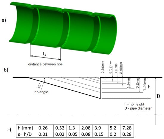
Figure 1.
Tube with cross ribs: (a) 3D view, (b) comparison of rib sizes, and (c) tested rib heights.

Table 1.
Longitudinal distances (the same for both geometries) between tested turbulizing elements, where L = Lr = Ld.
A constant rib inclination angle of 15° was assumed for all geometries, which means that, for different heights h, the dimension of its base also changed (Figure 1b).
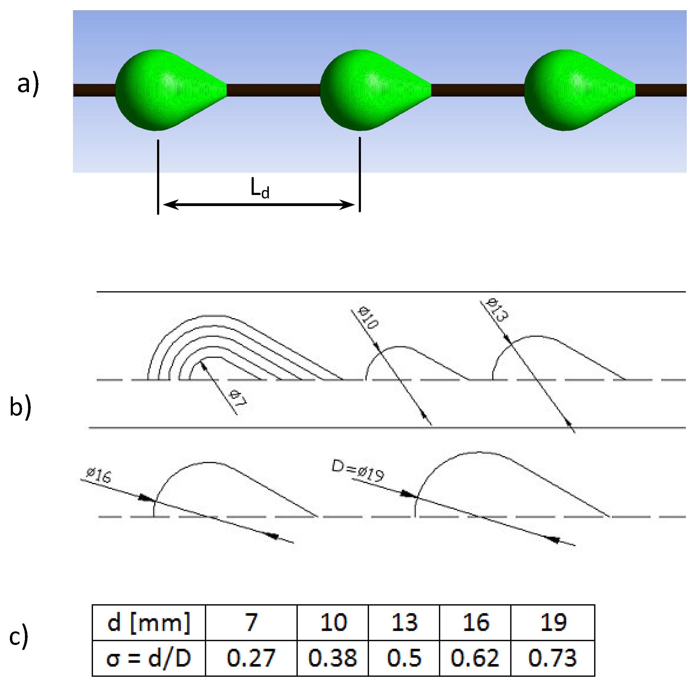
Figure 2 shows the second of the geometries studied: a turbulent insert with drop-shaped perturbation elements. This insert, like the finned pipe, was also numerically investigated over a wide range of geometric dimensions: 5 different “droplet” diameters d (Figure 2c) with 7 different longitudinal distances Ld between them, giving 5 × 7 = 35 different configurations. The longitudinal distances between the elements are given in Table 1 and were the same as for the finned pipe.

Figure 2.
Turbulizing insert: (a) 3D view, (b) comparison of the size of the “droplets”, and (c) dimensions of the diameters of the tested elements.
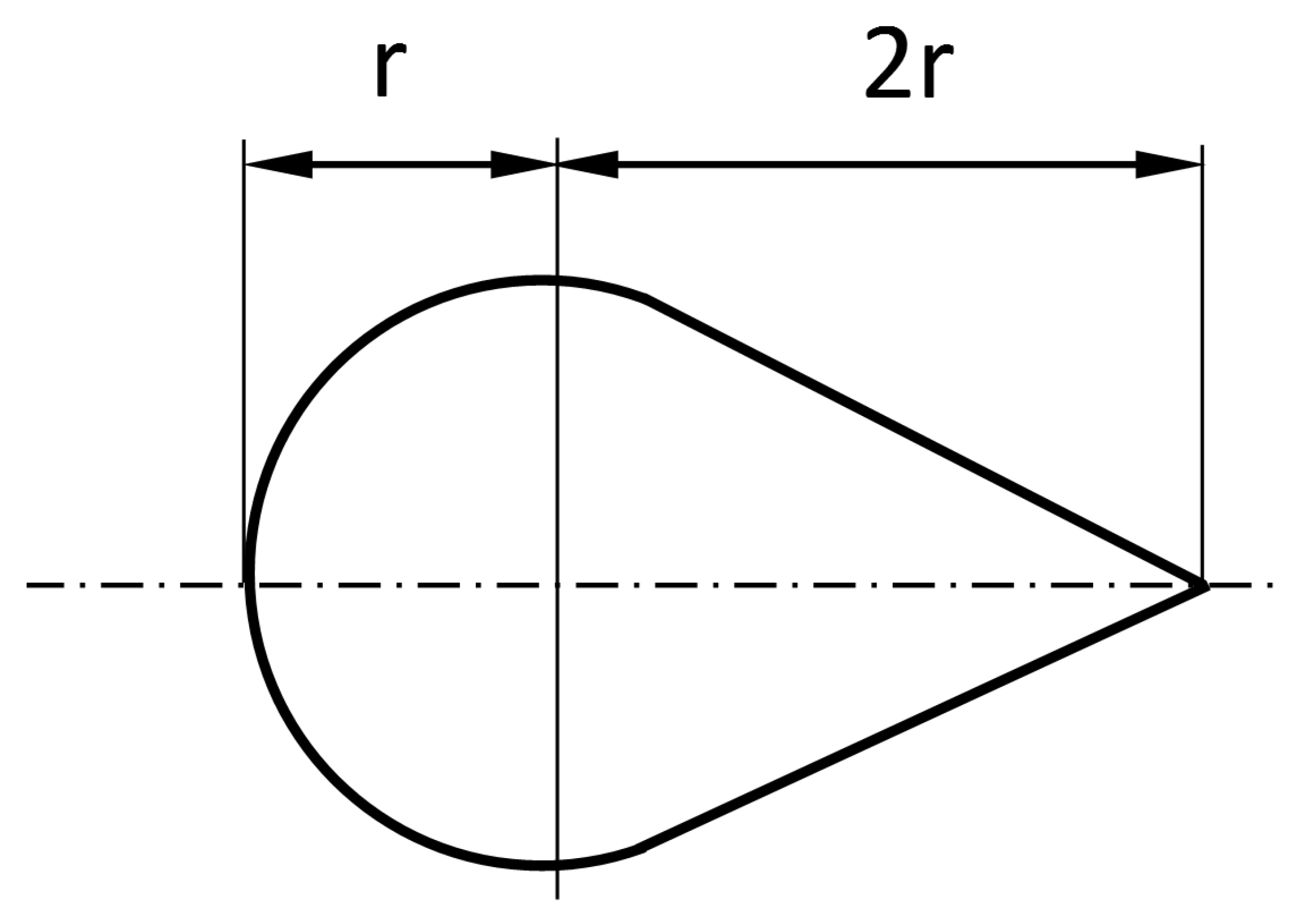
The length of the streamlined part of the disturbing element (the “tail of the drop”) was taken as 2r, which is equal to the diameter of the spherical part of the insert (Figure 3). Other lengths of 3r and 4r were also tested, which turned out to be slightly less favorable in terms of the quantity of entropy being generated in the system.

Figure 3.
Mutual proportions of insertion-disturbing elements.
The inner diameter of the finned tubes and the turbulent insert was the same and was 26 mm.
For each of these geometries, numerical simulations were carried out at 10 numerical simulations for different Reynolds numbers. (In addition to the entropy flux generated, data were obtained for each case to enable the preparation of thermal fluid characteristics, which were not included in this work). This gives 49 × 10 = 490 numerical simulations for the finned pipe and 35 × 10 = 350 simulations for the inserts. In total, 490 + 350 = 840 numerical simulations were performed for all cases studied.
3. Theoretical Background
The EGM optimization method considers the complete channel as a thermodynamic system in which two irreversible processes derived from heat transfer and fluid flow exist. The entropy generation in these processes depends mainly on the Reynolds number and heat transfer between the fluid and the channel wall. When increasing the Re number, due to an increase in frictional resistance, the entropy generated in the fluid flow process increases, while, in the heat transfer process, it decreases due to a decrease in temperature differences. Thus, the total entropy generated in a heat flow channel is the sum of the entropies derived from these two processes. Therefore, there is, for each channel geometry, a certain specific value of the Re number, called the optimal Re number, at which the thermodynamic system produces a minimum of entropy.
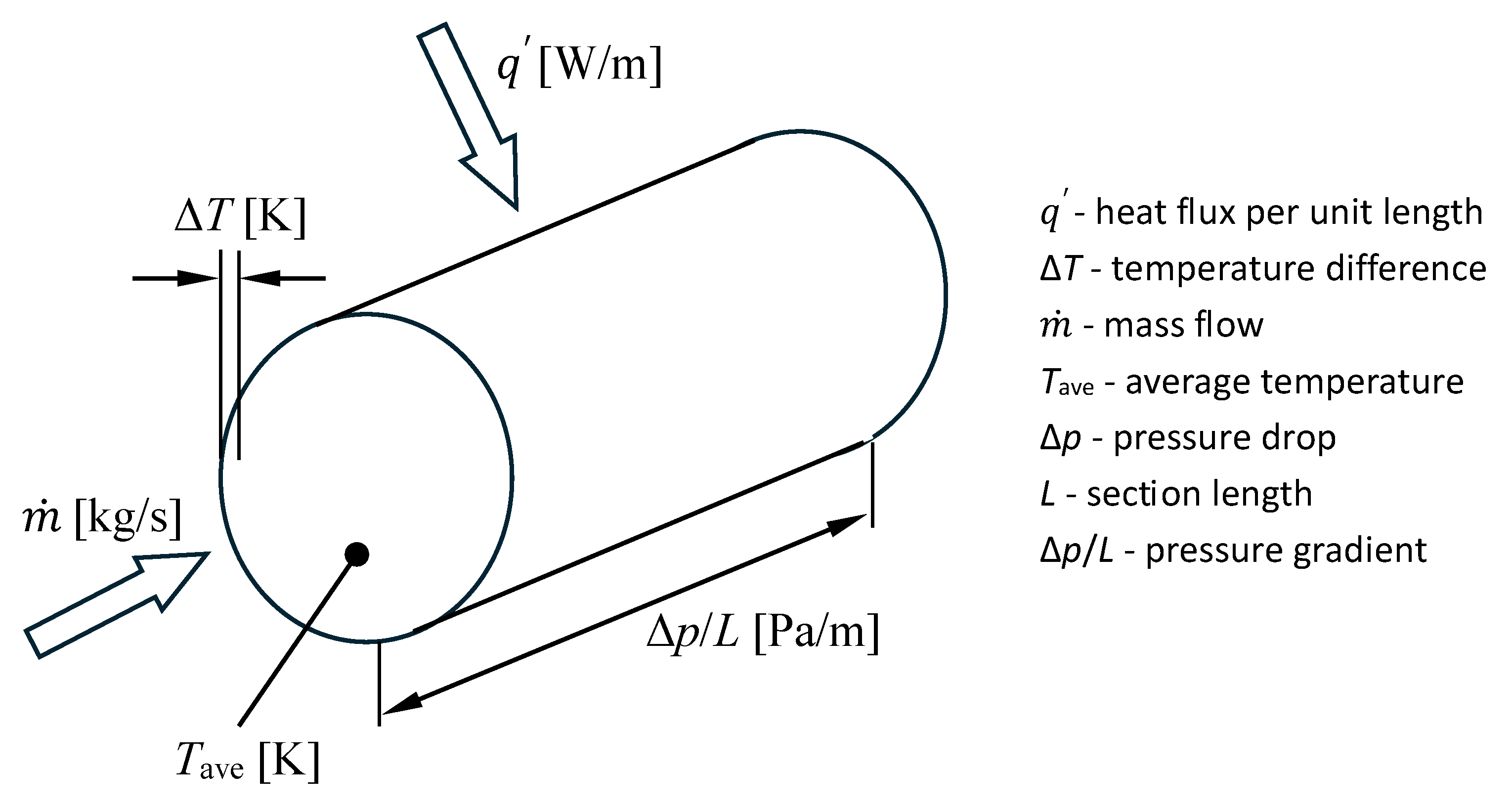
For the simplest flow channel, which is a smooth pipe (Figure 4), the basic relations were given by Bejan [1,14]. Two processes take place in that exemplary section of the pipe, i.e., heat transfer and fluid flow, and their irreversibility is caused by the temperature difference and pressure gradient, respectively. The equation describing the generation of total entropy S′gen has the following form.
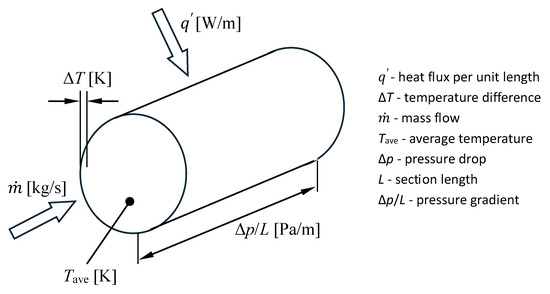
Figure 4.
Diagram of variable designations for Equation (2) in the smooth pipe elementary section.
For such an elementary pipe channel treated as a thermodynamic system, Bejan [1] gave a relation for the total entropy generated in a section of the channel length.
Well-known formulas were used to correlate for Nu number and flow resistance coefficient.
After substituting the appropriate variables into the formula and performing transformations, he obtained the formula for the entropy ratio [1]:
where Reopt is called the optimal Reynolds number and can be expressed as follows.
In (5), B is coefficient depending on mass flow, heat flux, and fluid properties.
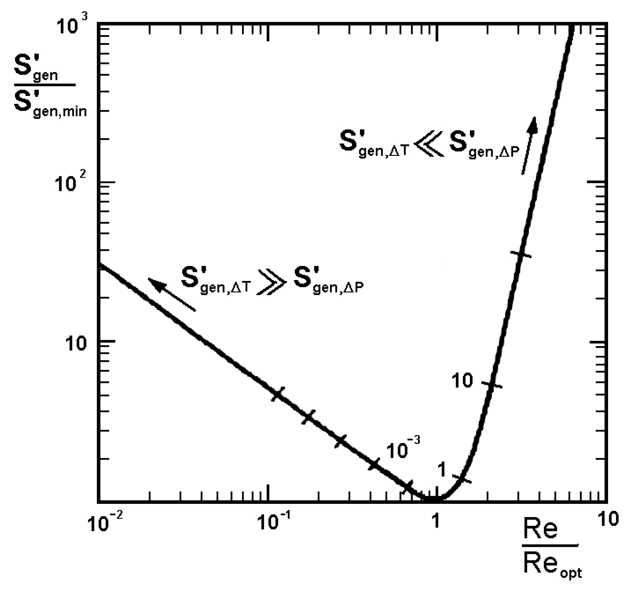
In Figure 5, a graphical illustration of Equation (4) is shown. This is a graph created on the basis of theoretical values, where the generated total entropy S′gen is normalized by the generated minimum entropy of the thermodynamic system S′gen,min. Based on numerical simulations of the same flow channel section, the same graph can be plotted, but Equation (2) is required to calculate the total entropy S′gen.
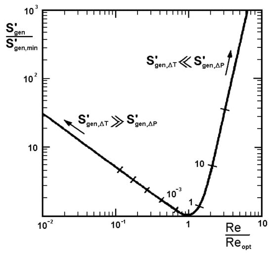
Figure 5.
The relative entropy generation for forced convection heat transfer in a smooth tube [1].
The ratio of the dimensionless entropy of the studied channels is referred to as the minimum entropy generated in a smooth pipe for the same flow parameters. The generated total entropy in the studied channel S′gen is calculated from the results of numerical simulations (using Equations (5) and (6)), whereas the minimum entropy generated by the system S′gen,min is calculated for the smooth pipe from theoretical relations (3), using the exact same boundary conditions as in the numerical calculations. This approach makes it possible to relate and compare the results of the studied channels to the smooth pipe. In Figure 5, the values of generated entropy S′gen,ΔT derived from the heat transfer process are located on the left side of the diagram, while on its right side (values greater than Re/Reopt = 1) is the entropy generated by the flow resistance S′gen,Δp.
4. Numerical Simulation
4.1. Geometrical Model
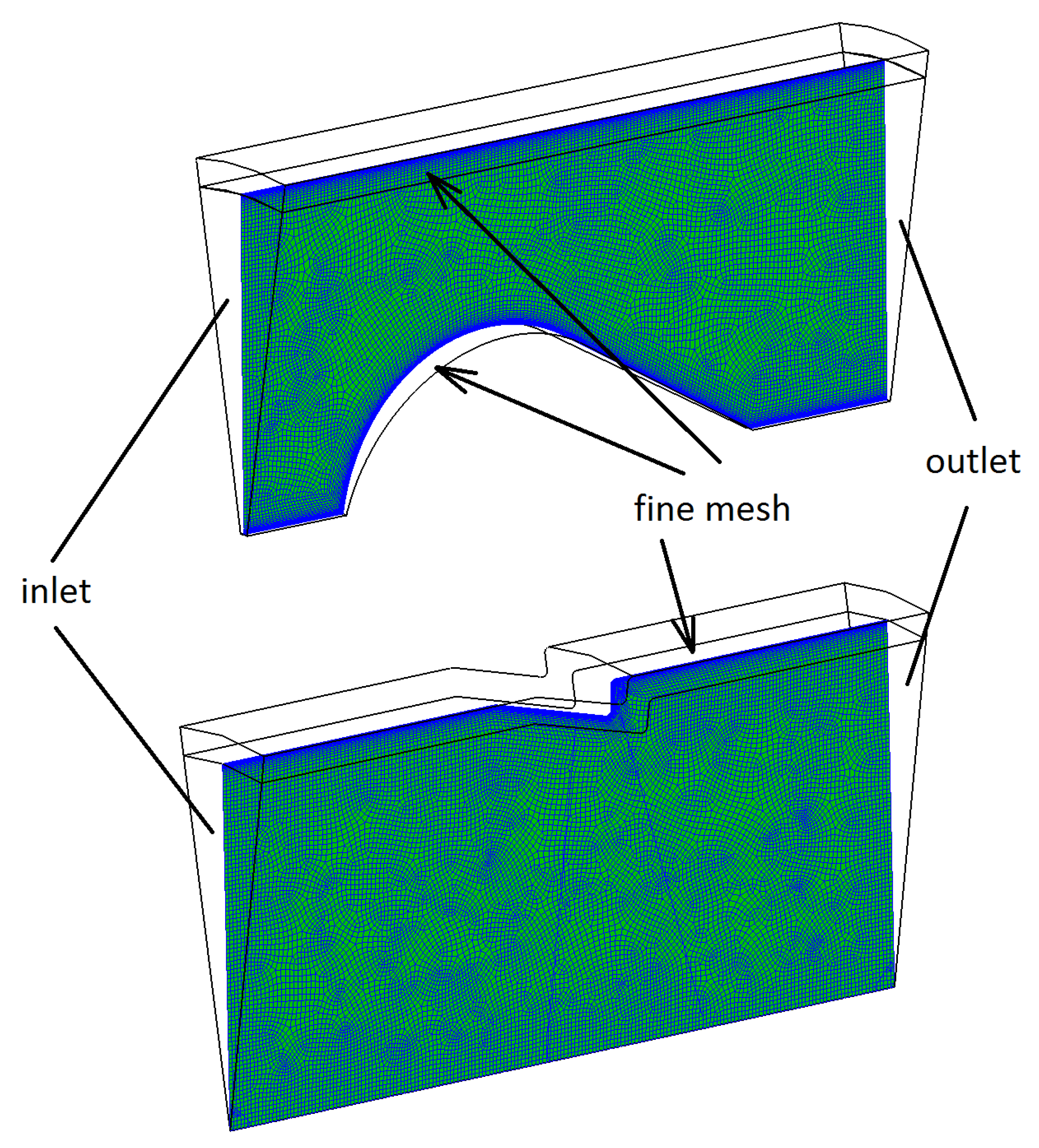
In the geometries considered, the flow is axisymmetric due to the lack of factors that would cause a transverse component of velocity in relation to the fluid inlet domain. Therefore, such tasks can be treated as two-dimensional. However, since the solver of the ANSYS CFX v. 18.1 computational program is based on the FV method (Finite Volume), the domain has to be a 3D body but with the boundary conditions applied as for a 2D body. For the numerical calculations, a simplified pipe geometry was used, as in Figure 6, with the shape of a cylinder cut out, where the length of the considered domain was L and the angle of opening was 10°. On the sides of the domain, the axial symmetry was set as boundary conditions enforcing two-dimensional flow. The working fluid in each calculated case was water with an average temperature of 30 °C.
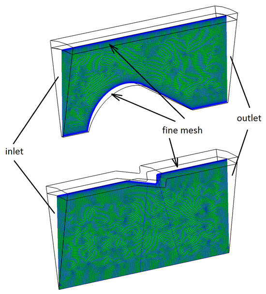
Figure 6.
Repetitive and periodic segments of the tested pipes as computational domains.
4.2. Boundary Conditions
The idea of numerical research for a single repetitive section of a thermal fluid channel is based on inducing the hydraulically and thermally fully developed flow in it. The ANSYS CFX computational program allows for the use of such a test method, which allows for focusing the computational process on a repetitive section of the channel, and which is representative of the entire channel [10,13,14,15,16,17]. Obtaining fully developed flow in such a short section of pipe required setting non-standard boundary conditions. Translational periodicity was applied at the inlet and outlet of the domain, and the force inducing the flow was the pressure gradient.
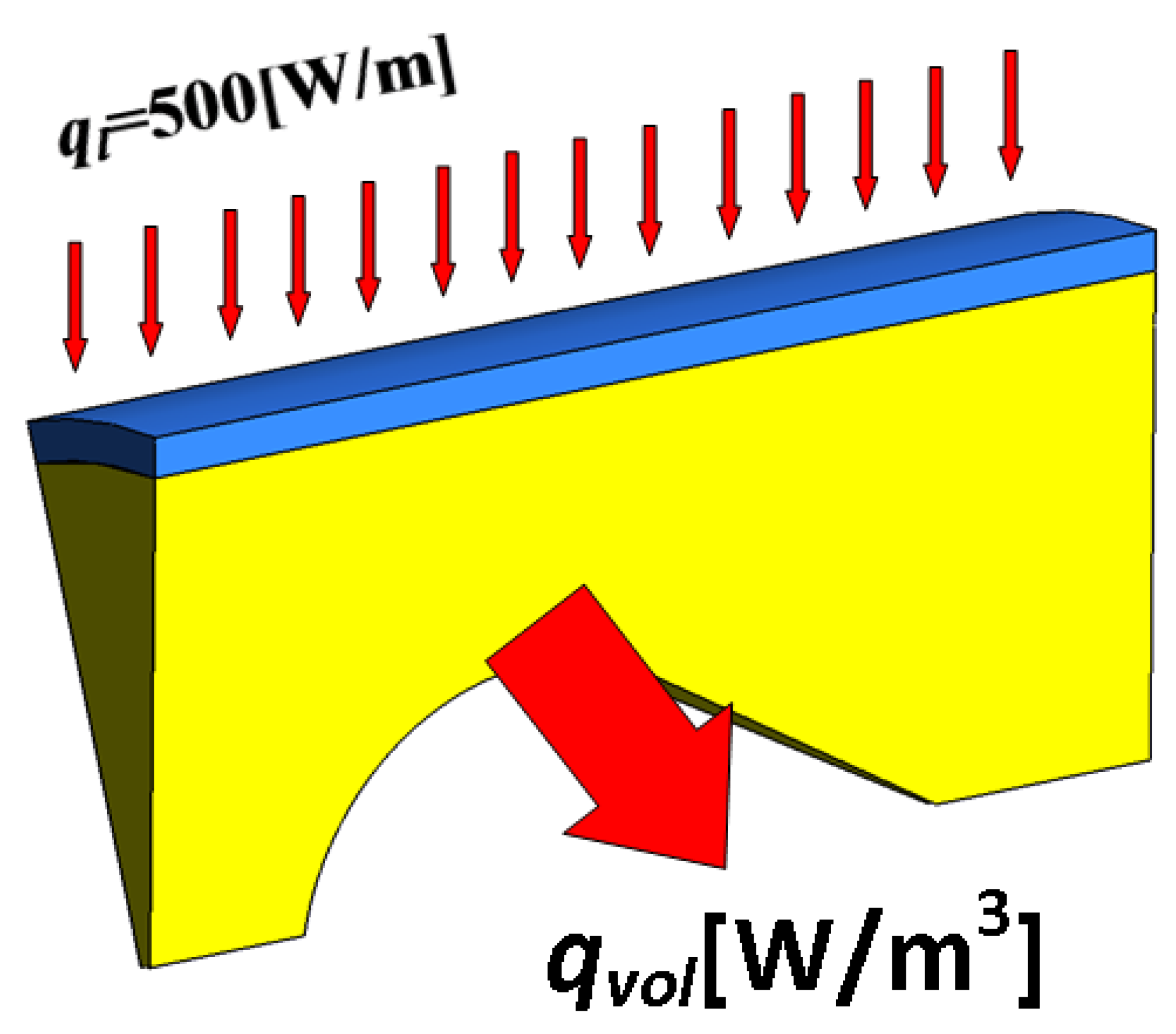
Also, a non-standard approach had to be used to set the thermal boundary conditions. A constant heat flux of 500 W/m (per unit length of the channel), Figure 7, was set on the pipe wall, while, to receive and balance the supplied heat to the domain, a volumetric energy source of negative sign was used, equal in value to the heat supplied to the domain wall.
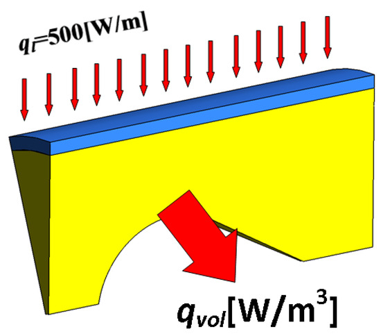
Figure 7.
Repeated and periodic segment of the pipes under study. Heat transfer diagram in the computational domain.
In general, the assumption of such a numerical model is to study a repetitive fragment of the channel geometry, rather than its entire length. This approach allows us to increase the accuracy and quality of the computational mesh and at the same time significantly reduce the computational time of each analyzed case.
4.3. Grid Independence
Prior to performing the main simulations, a test of computational mesh independence on the obtained numerical results was performed for several selected geometries. Due to the different size of the domains of the cases studied, a parameter relating to the average grid cell volume and not to the direct number of nodes in the geometry was monitored. Meshes with the following average cell sizes H × H × H [mm] and corresponding volumes Vcell [mm3], H3 = Vcell → 23 = 8, 13 = 1, 0.753 = 0.422, 0.53 = 0.125, 0.43 = 0.064, 0.33 = 0.027, 0.23 = 0.008 [mm3], were tested. When testing the meshes, the monitored parameters were the average temperature in the domain, the average velocity, and the y+ coefficient, which informs the quality of the mesh in the boundary layer. A minimum mesh density of 0.43 = 0.064 [mm3] was determined, at which further densification of the mesh resulted in a change in average velocity of about 1% and average temperature of about 1.5%, while increasing the number of nodes by about 3 times. Such accuracy is, therefore, a balance between accuracy and calculation time. At the same time, by the local densification of the near-wall layer, the y+ parameter was maintained at a level appropriate for the given turbulence model in all tested geometries.
4.4. Turbulence Model
A k-ω SST (Shear Stress Transport) turbulence model was performed for all numerical simulations. This is one of the most widely applied models in CFD calculations thanks to its much better representation of thermal fluid phenomena in cases with jet separation, which is characteristic of the flow of the studied inserts, compared to the standard k-ε model [18].
The SST model’s main feature is its ability to perform calculations in the viscous sublayer by using the k-ω model close to the wall and using the standard k-ε model in the turbulent core away from the wall. A special “blending function” is implemented in the SST model [18,19], which is responsible for selecting and switching the appropriate model for calculation depending on the distance from the wall. According to the recommendations for mesh density in the near-wall layer, the SST turbulence model requires at least several nodes of the computational mesh in this region so that the condition y+ < 2, and this was achieved in all calculations [18].
A comparison with experimental measurements and the validation of these two turbulence models, SST and k-ε, was also reported in [20].
5. Results and Discussion
Due to the large number of simulations, only the results for a few selected longitudinal L/D distances as a representative of the whole are shown. Two types of graphs are presented: S′gen(Re)-total entropy flux vs. Reynolds number (Figure 8, Figure 10 and Figure 14) and (S′gen/S′genmin)/(Re/Reopt)-relative entropy vs. dimensionless Reynolds number (Figure 9, Figure 11 and Figure 13). In each figure, graphs with the results are shown side by side, (a) for pipe with insert and (b) for a finned pipe, in order to compare the generated entropy of the tested geometries with the same longitudinal distances of the disturbing elements. In each graph, the entropy generated in a smooth pipe of the same diameter is shown as a reference level as well. Figure 8 shows the flux of entropy generated as a function of the Re number for a distance L/D = 0.77. The analysis of the results of the tested inserts shows (Figure 8a) that the position of the minimum of each insert is essentially at the same level as for the smooth tube S′gen ≈ 0.04 [W/mK]. They differ only in the number of Re at which this minimum occurs. A pipe with an insert disruption element with dimensions σ = d/D = 0.5 has a minimum of generated entropy at about Re = 100,000, while, for a smooth pipe, it is Re = 110,000.
The pipe with ribs (Figure 8b) shows much smaller values of minima of generated entropy than the pipe with an insert. The least entropy (lowest minimum) is generated by the pipe with ribs with the lowest height ε = 0.01. The absolute value of this minimum is S′gen ≈ 0.02 [W/mK] and is approx. two times smaller than for a smooth pipe at Re ≈ 105,000. Ribs with other ε heights generate more irreversible entropy, while their minima fall at lower Re numbers (e.g., for ε = 0.15 Re ≈ 65,000).
Figure 9 shows a graph depicting the generated relative entropy as a function of the dimensionless Reynolds number. The reference is a smooth pipe, for which the minimum of the generated entropy is located at the intersection of the axes, i.e., at the “ones”, exactly as in Figure 5. The results obtained from the computer simulation for S′gen are divided (normalized) by the minimum value of the entropy S′genmin that a smooth pipe would have at the same Re number, according to Formula (7).
As can be seen, all minima, both for the insert and finned pipes, lie below 1, i.e., they generate correspondingly less irreversible entropy than the smooth pipe. The smallest minimum from the inserts tested is generated by the σ = 0.5 geometry (Figure 9a), which is about 0.8 compared to the value of 1.0 (100%) for the smooth pipe, simultaneously shifting the minimum toward dimensionless Re numbers less than 1 (Re/Reopt ≈ 0.65). For the finned pipe, the minima of dimensionless entropy S′gen/S′gen,min reach even lower values: from about 0.65 for ε = 0.15 to about 0.47 for ε = 0.01.

Figure 8.
Total entropy generation rate for dimensionless longitudinal distance L/D = 0.77: (a) pipe with insert and (b) ribbed pipe.
Figure 8.
Total entropy generation rate for dimensionless longitudinal distance L/D = 0.77: (a) pipe with insert and (b) ribbed pipe.
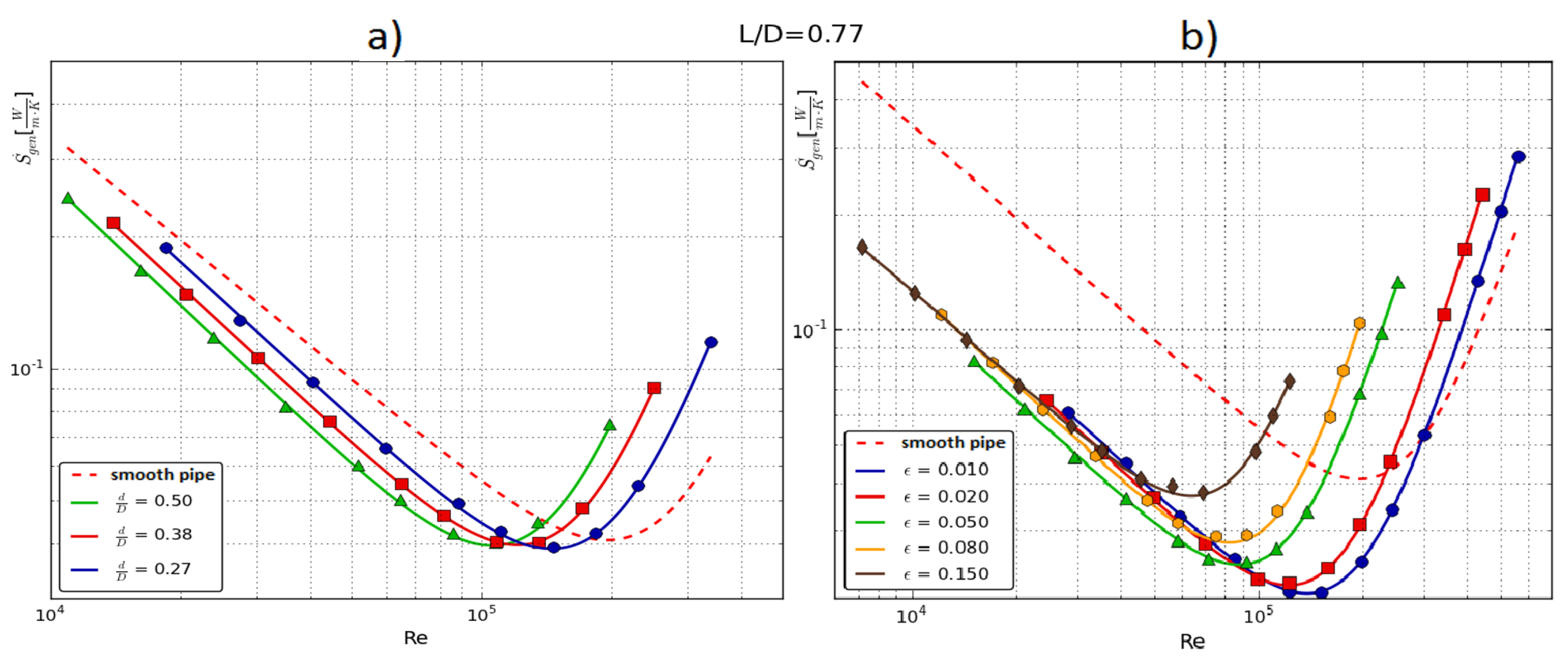
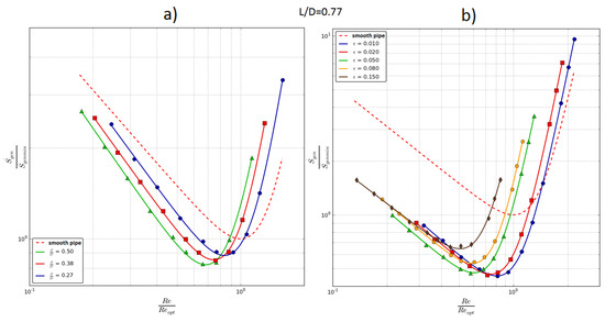
Figure 9.
Relative entropy generation rate for dimensionless longitudinal distance L/D = 0.77: (a) pipe with insert and (b) ribbed pipe.
Figure 9.
Relative entropy generation rate for dimensionless longitudinal distance L/D = 0.77: (a) pipe with insert and (b) ribbed pipe.
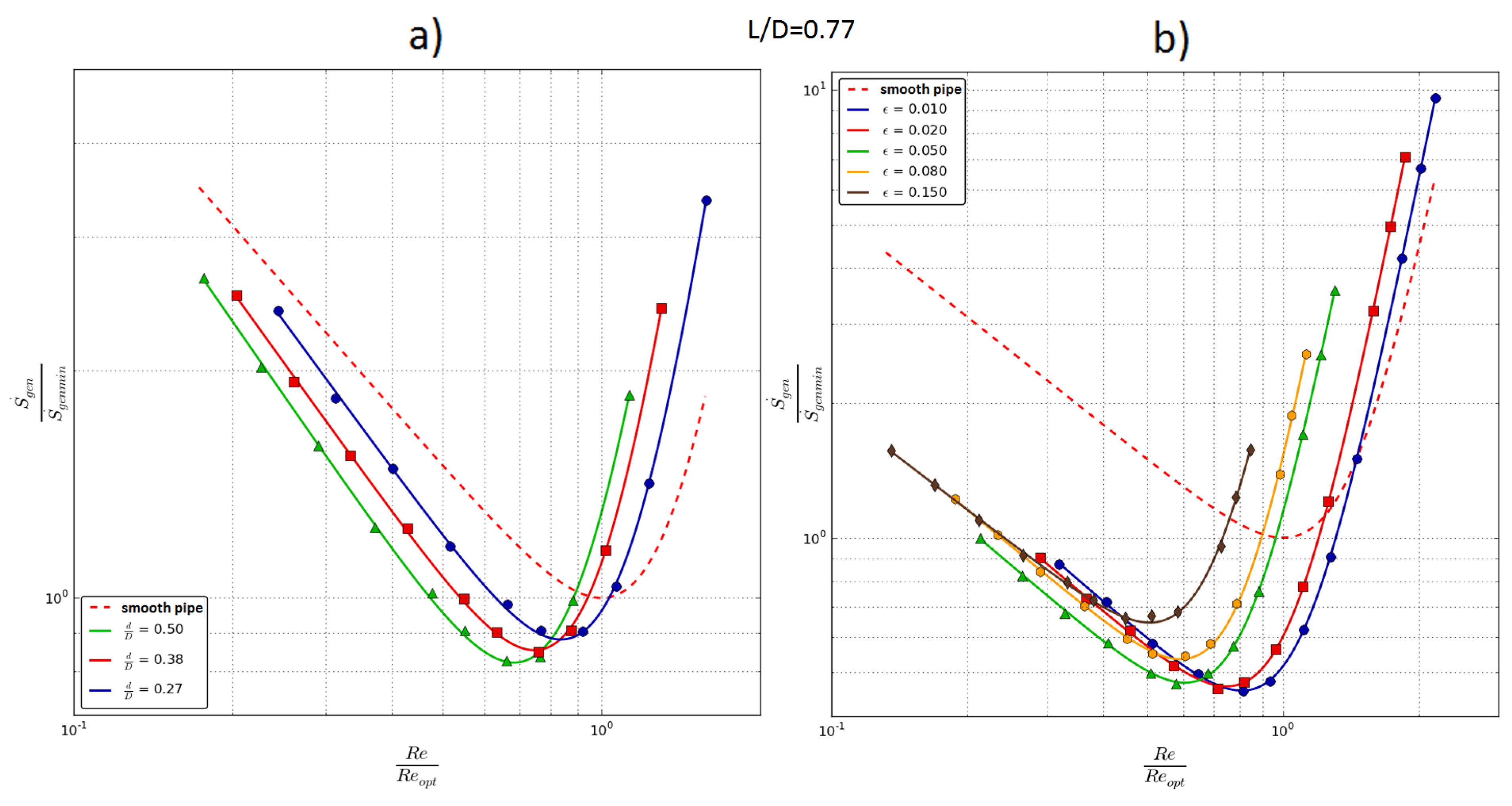
The analysis shows that, with a longitudinal distance of L/D = 0.77, the most favorable geometric configuration has the pipe with the smallest rib height ε = 0.01, which generates only about 47% of the irreversible entropy during the thermal fluid process compared to the smooth pipe. In addition, for both pipes with insert and finned, a certain regularity can be observed in the position of these curves on the graphs. For the finned pipes, the smallest values of generated entropy occur for the smallest disturbing elements ε = 0.01, and the largest for the largest ε = 0.15. On the other hand, for an insert pipe, the opposite is true: the smallest values of generated entropy occur for the largest disturbance elements d/D = 0.5, and the highest entropy is generated for the smallest insert elements d/D = 0.27
Figure 10 shows the flux of total generated entropy for a larger longitudinal spacing of the disturbing elements L/D = 1.38. As for the smaller L/D spacing (Figure 8a), for the insert, the minima have a value comparable to that for the smooth pipe, i.e., about 0.04 [W/mK], while they occur at smaller Re numbers (Figure 10a). For a finned pipe, on the other hand, the most favorable rib height is also ε = 0.01, where the minimum entropy generated has a value of about 0.02 [W/mK]. It is worth noting that, in absolute terms, the pipe with the highest rib height (ε = 0.28) generates a higher entropy flux than the smooth pipe (Figure 10b).
Figure 11 shows plots of generated relative entropy for L/D = 1.38. As with smaller longitudinal distances, the same order of position of the curves can be observed. The insert (Figure 11a) with the largest diameter of the “droplets” generates, relatively, the least entropy, and its minimum reaches a value of about 75% of the minimum of the smooth pipe, with a dimensionless Re number of about 0.55. The smaller the diameter of the insert elements, the more entropy generated relative to the smooth pipe.
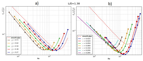
Figure 10.
Total entropy generation rate for dimensionless longitudinal distance L/D = 1.38: (a) pipe with insert and (b) ribbed pipe.
Figure 10.
Total entropy generation rate for dimensionless longitudinal distance L/D = 1.38: (a) pipe with insert and (b) ribbed pipe.
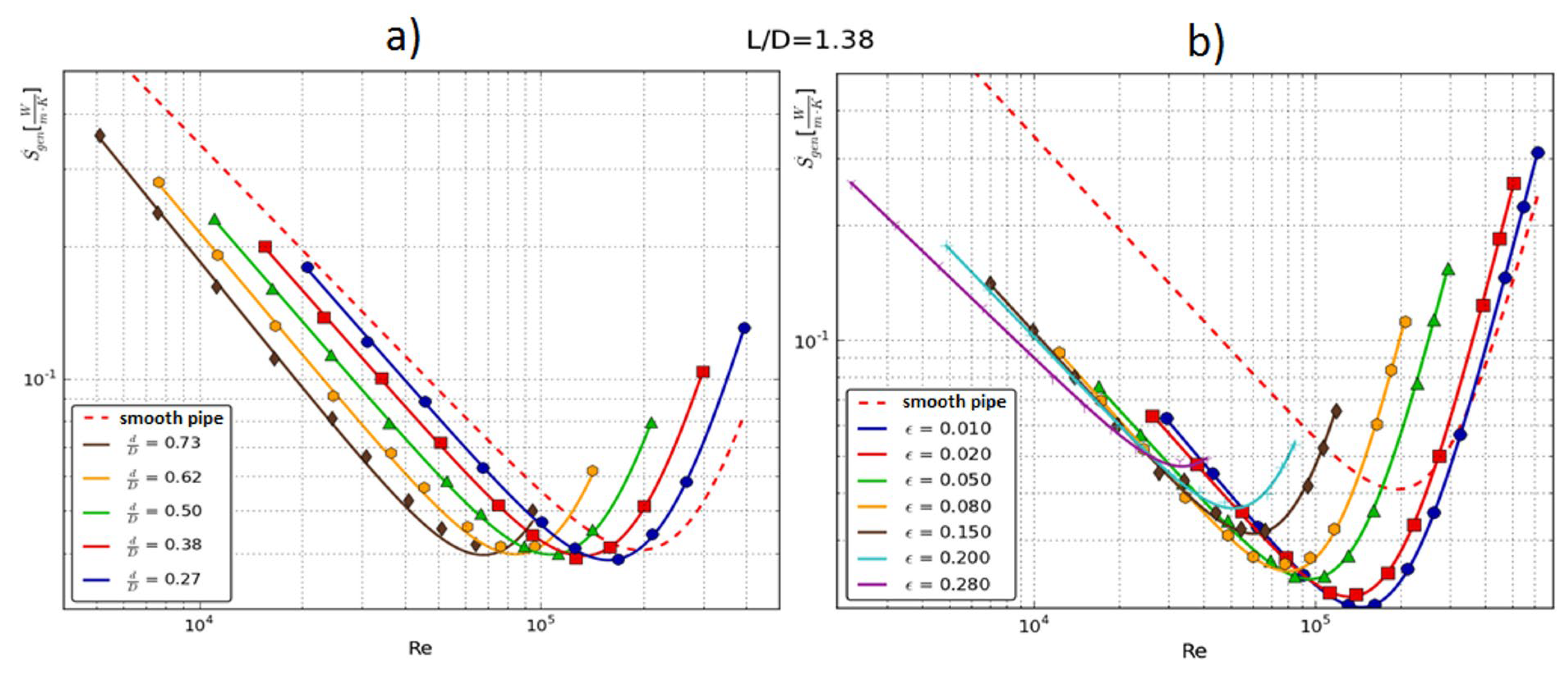
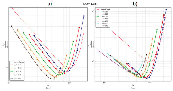
Figure 11.
Relative entropy generation rate for dimensionless longitudinal distance L/D = 1.38: (a) pipe with insert and (b) ribbed pipe.
Figure 11.
Relative entropy generation rate for dimensionless longitudinal distance L/D = 1.38: (a) pipe with insert and (b) ribbed pipe.
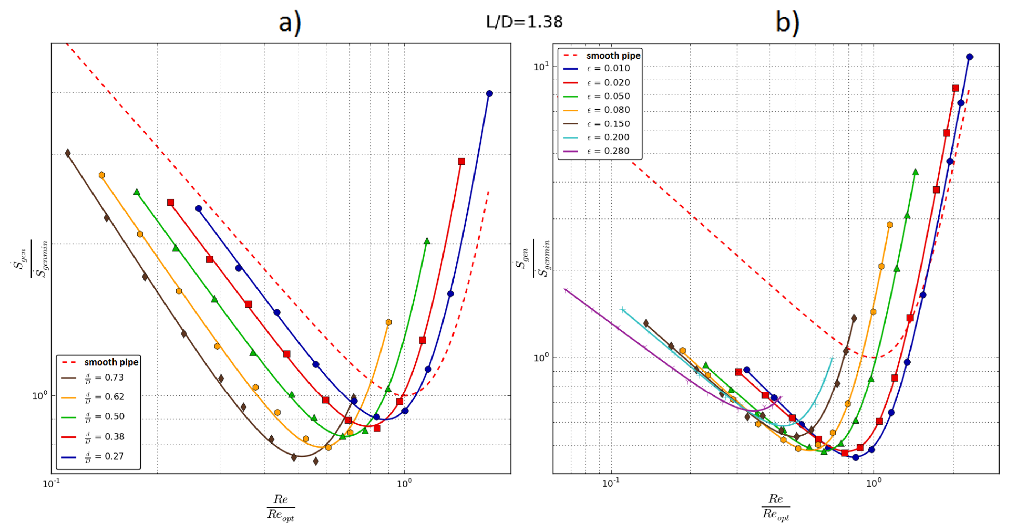
For the finned pipe, as for the distance L/D = 0.77, it follows that the most favorable geometry has a pipe with ε = 0.01. It also generates approx. 47% irreversible entropy relative to the smooth pipe. In addition, as with the smaller L/D, the smallest values of generated entropy occur for the smallest disturbing elements (ε = 0.01) and the largest for the largest (ε = 0.15).
A very similar situation as for smaller L/D occurs for the largest longitudinal distance between elements L/D = 3.27 (Figure 12 and Figure 13a). However, this is interesting to note for the difference in the location of the relative entropy curves for the finned tube (Figure 13b). At smaller longitudinal distances, the pipe with the smallest ribs generated, relatively, the least irreversible entropy (ε = 0.01). In such a case, the values of the minimum dimensionless entropy for ribs ε = 0.01 and ε = 0.28, i.e., for the smallest and largest ribs, are practically the same, about 0.47.
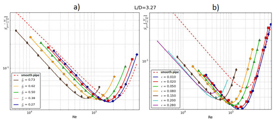
Figure 12.
Total entropy generation rate for dimensionless longitudinal distance L/D = 3.27: (a) pipe with insert and (b) ribbed pipe.
Figure 12.
Total entropy generation rate for dimensionless longitudinal distance L/D = 3.27: (a) pipe with insert and (b) ribbed pipe.
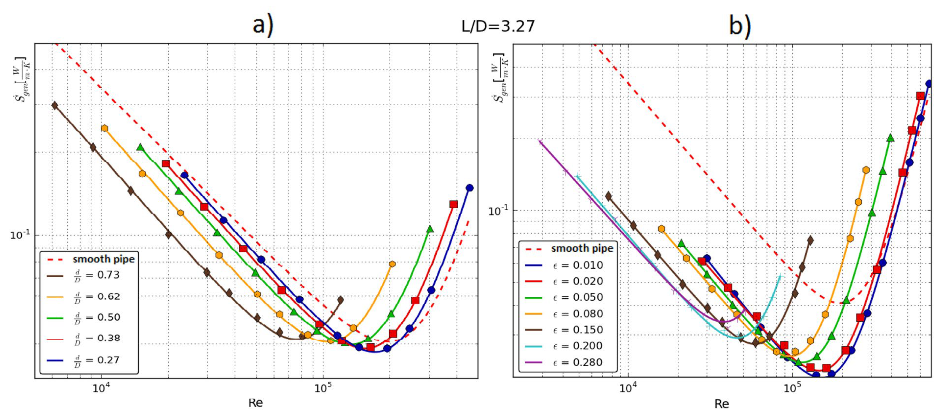
Figure 13.
Relative entropy generation rate for dimensionless longitudinal distance L/D = 3.27: (a) pipe with insert and (b) ribbed pipe.
Figure 13.
Relative entropy generation rate for dimensionless longitudinal distance L/D = 3.27: (a) pipe with insert and (b) ribbed pipe.
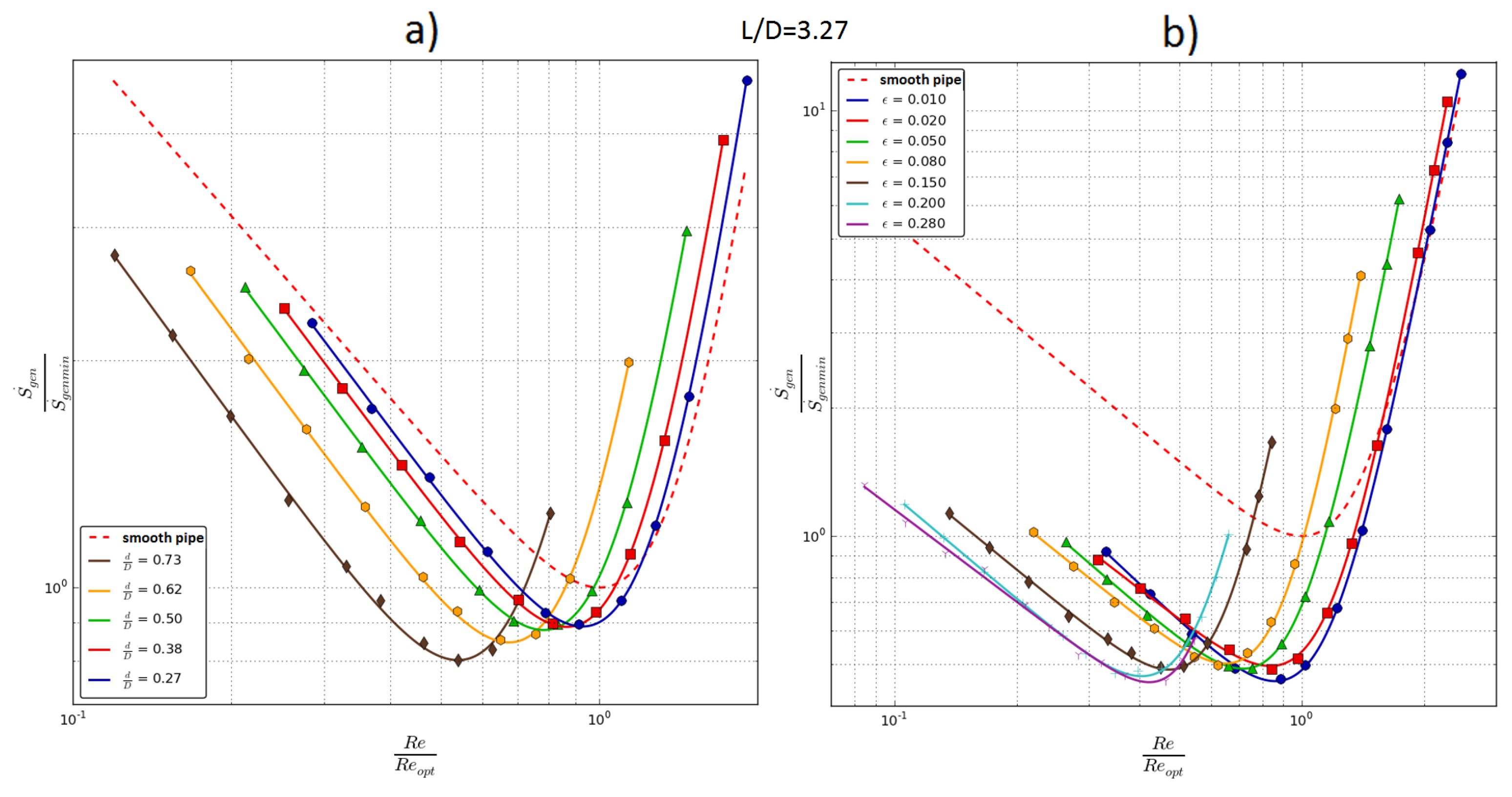
However, taking into account the relative Re number (about 0.42 for ε = 0.28 and about 0.9 for ε = 0.01) at which this minimum occurs, it is definitely more favorable for the pipe with the largest ribs due to its smaller value than for the smooth pipe.
This case proves that, for larger longitudinal distances, the order of the position of the curves corresponding to the different rib geometries can be “disturbed”. However, considering the flux of total entropy generated, according to Figure 8b, Figure 10b and Figure 12b, the smallest value of the minimum occurs for a pipe with ribs ε = 0.01.
6. Type of Intensification of Heat Transfer
The aim of the presented investigations was to compare the efficiency of the two channels in different ways of intensifying the heat transfer: with the insert (turbulizing flow in the pipe core) and with the internal ribs (turbulizing flow at the pipe wall). The tested channels have a different flow structure that affect the intensity of heat transfer from the pipe to the fluid. A key aspect is a different way of reducing the laminar boundary layer (having a main influence on the heat transfer) in both geometries.
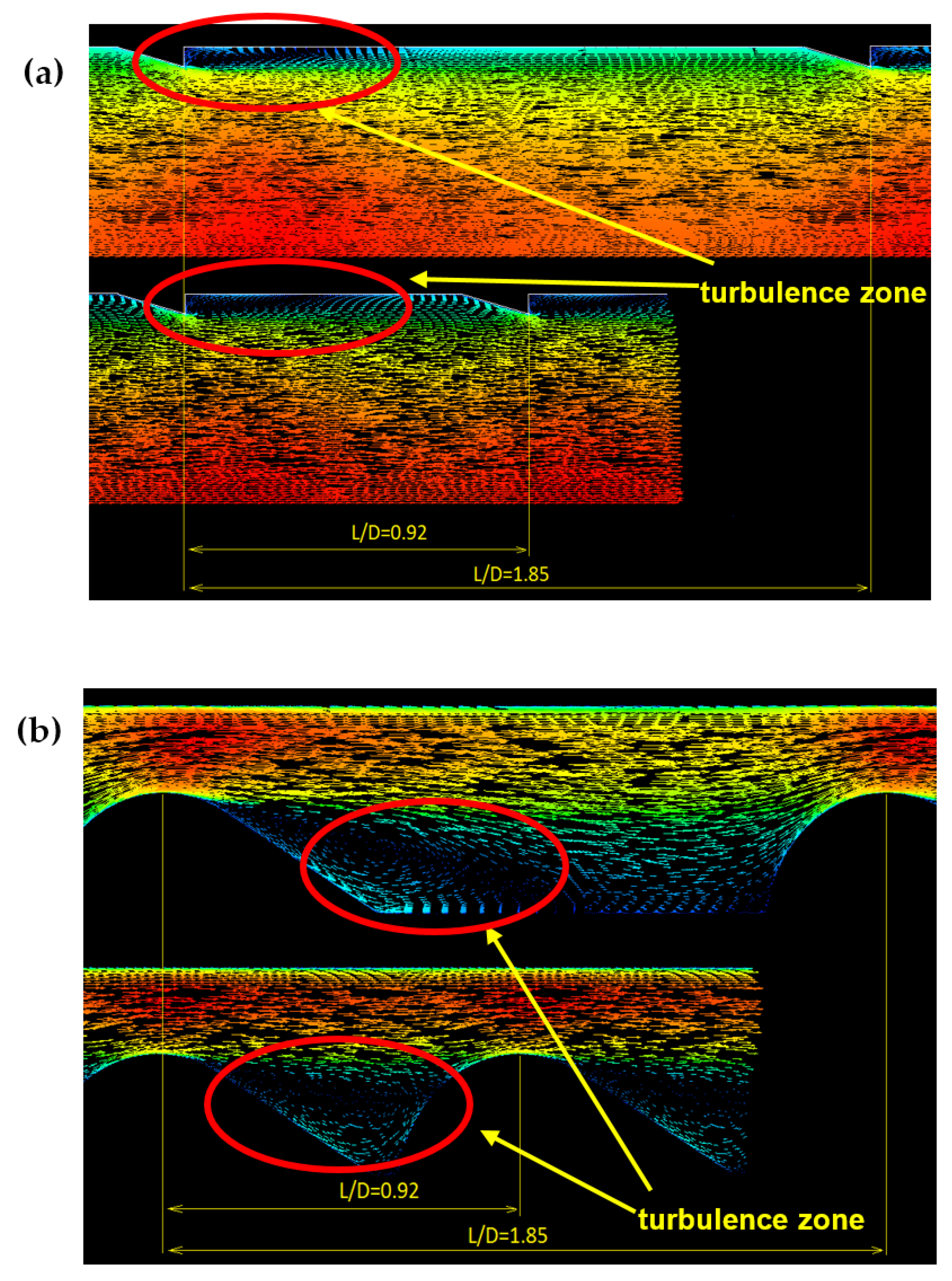
In the ribbed tube showed in Figure 14a, the flow is disturbed on the wall, so, directly in the laminar boundary layer. The ribs cause the local breaking of this layer, increasing turbulence, vortices generation, and reverse flow behind the rib and in close proximity to the wall. A characteristic feature of this geometry is the small influence of the ribs (especially those with a low height) on the flow in the pipe core: it remains practically undisturbed.
For the pipe with the insert (Figure 14b), the flow structure is different in nature. The insert is placed in the axis of the tube, which forces the flow around the elements, causing a local increase in fluid velocity at the wall, but without its turbulization. In regions with increased velocity (red vectors in Figure 14b), the thickness of the laminar boundary layer is reduced, causing local heat transfer intensification. In this flow, there is no direct rapture of the boundary layer, while, between the elements of the insert (“drops”), the vortices and the reverse flows are formed, and the turbulence increase is also associated with them.
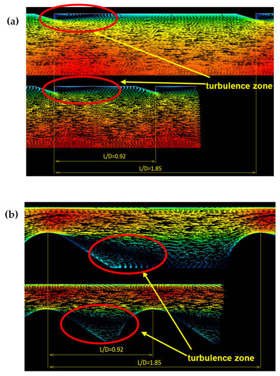
Figure 14.
Velocity vector map for the two chosen longitudinal distances with marked turbulence zones: L/D = 0.92 and L/D = 1.85, (a) ribbed pipe, and (b) pipe with insert.
Figure 14.
Velocity vector map for the two chosen longitudinal distances with marked turbulence zones: L/D = 0.92 and L/D = 1.85, (a) ribbed pipe, and (b) pipe with insert.
7. Conclusions
This paper shows the results of numerical simulations where the optimization analysis was carried out using the EGM method. The effect of the two geometric parameters of each channel on the quantity of generated entropy was tested and a comparison was made between them. For the channel with the turbulizing insert, these parameters are the diameter of the insert element (“drop”) and the distance between them, while, for the finned tube, these are the rib height and the longitudinal distance between them. The most significant novelty resulting from presented research is the determination that the turbulization of flow in the pipe wall layer generates significantly less irreversible entropy than the disturbance of flow in the pipe axis by the insert.
The results obtained are presented in the form of two types of graphs: S′gen(Re), the entropy-generated rate as a function of Re (Figure 8, Figure 10 and Figure 12), and S′gen/S′min(Re/Reopt), the relative entropy rate as a function of dimensionless Re number (Figure 9, Figure 11 and Figure 13), wherein S′min and Reopt refer to a smooth tube with the same diameter. On each figure, the graphs of the two tested geometries are shown side-by-side in order to compare them at the same longitudinal distance L/D of turbulizing elements. The analysis showed that, for almost all of the tested geometry, the minimum of the total generated entropy is smaller than for a smooth tube: diagrams S′gen(Re). When comparing the two studied geometries, the one with the greater benefit definitely turned out to be the ribbed tube. This is due to the nature of the flow, where the direct disorder of the continuity of boundary layer by the rib is found to have a lower impact on the amount of entropy generated in the heat flow process.
The pipe with the smallest rib height, h = 0.26 mm (ε = 0.01), definitely proved to be the most advantageous in terms of generating the amount of entropy (Figure 9b, Figure 11b and Figure 13b), and, also, it has the lowest value of minimum S′gen/S′min ≈ 0.47 for all tested distances L/D. In Figure 13b, which is for the largest distance L/D = 3.27, some “disruption” can be observed in the curve arrangement, which does not correspond to the order of the decreasing size of ribs; the greatest ribs ε = 0.2 and ε = 0.28 generate the same amount of minimum entropy, about 0.47, but at a smaller dimensionless Re number (Re/Reopt). This means that, for larger distances L/D, the largest ribs may be the more preferred geometry.
The presented EGM method can be used to determine both the appropriate geometry of the flow channel (mainly in a design phase) and/or to determine the appropriate parameters of the heat flow process, i.e., finding the thermodynamic optimum, and also for calculating exergy losses, e.g., using the Gouy–Stodola theorem.
Author Contributions
Conceptualization, P.B.J.; methodology, P.B.J.; validation, P.B.J.; investigation, P.B.J.; writing—original draft preparation, P.B.J., G.G. and Z.C.; writing—review and editing, P.B.J., G.G. and Z.C.; supervision, P.B.J. All authors have read and agreed to the published version of the manuscript.
Funding
This research received no external funding.
Data Availability Statement
The original contributions presented in the study are included in the article, further inquiries can be directed to the corresponding author.
Conflicts of Interest
The authors report no conflicts of interest.
Nomenclature
| D | pipe diameter (mm) |
| d | “drop” diameter (mm) |
| f | friction factor (-) |
| h | rib height (mm) |
| L | pipe length (mm) |
| m | mass flow rate through the duct (kg/s) |
| q′ | unit heat flux (W/m) |
| Reopt | optimal Reynolds number |
| S′gen | generation of total entropy rate (W/mK) |
| S′gen, min | generation of minimum entropy rate (W/mK) |
| S′gen,ΔT | entropy generation from heat transfer (W/mK) |
| S′gen,Δp | entropy generation from pressure drop (W/mK) |
| Tav | average temperature (K) |
| Nu | Nusselt number (-) |
| Re | Reynolds number (-) |
| Pr | Pandtl number (-) |
| y+ | non-dimensional wall distance (-) |
| ε | non-dimensional rib height (-) |
| σ | non-dimensional pipe diameter (-) |
References
- Bejan, A. Advanced Engineering Thermodynamics, 2nd ed.; Wiley-Interscience: Hoboken, NJ, USA, 1997. [Google Scholar]
- Tandiroglu, A. Effect of flow geometry parameters on transient entropy generation for turbulent flow in circular tube with baffle inserts. Energy Convers. Manag. 2007, 48, 898–906. [Google Scholar] [CrossRef]
- Yakut, K.; Sahin, B.; Canbazoglu, S. Performance and flow-induced vibration characteristics for conical-ring turbulators. Appl. Energy 2004, 79, 65–76. [Google Scholar] [CrossRef]
- Yakut, K.; Sahin, B. Flow-induced vibration analysis of conical rings used of heat transfer enhancement in heat exchanger. Appl. Energy 2004, 78, 273–288. [Google Scholar] [CrossRef]
- Sahiti, N.; Krasniqi, F.; Fejzullahu, X.; Bunjaku, J.; Muriq, A. Entropy generation minimization of a double-pipe pin fin heat exchanger. Appl. Therm. Eng. 2008, 28, 2337–2344. [Google Scholar] [CrossRef]
- Kurtba, I.; Durmuş, A.; Eren, H.; Turgut, E. Effect of propeller type swirl generators on the entropy generation and efficiency of heat exchangers. Int. J. Therm. Sci. 2007, 46, 300–307. [Google Scholar] [CrossRef]
- Ogulata, R.T.; Doba, F. Experiments and entropy generation minimization analysis of a cross-flow heat exchanger. Int. J. Heat Mass Transf. 1998, 41, 373–381. [Google Scholar] [CrossRef]
- Vargas, J.; Bejan, A. Thermodynamic optimization of finned crossflow heat exchangers for aircraft environmental control systems. Int. J. Heat Fluid Flow 2001, 22, 657–665. [Google Scholar] [CrossRef]
- Iyengar, M.; Bar-Cohen, A. Least-energy optimization of forced convection plate-fin heat sinks. IEEE Trans. Compon. Packag. Technol. 2003, 26, 62–70. [Google Scholar] [CrossRef]
- Jasiński, P. Numerical optimization of flow-heat ducts with helical micro-fins, using Entropy Generation Minimization (EGM) method. In Proceedings of the WSEAS International Conferences (HTE’11), Florence, Italy, 23–25 August 2011; pp. 47–54. [Google Scholar]
- Sakkay, M.; El Ghandouri, I. Enhancing heat transfer efficiency and entropy generation minimization in Micro-Channel Heat Sinks through pillar spacing and diameter optimization. Int. J. Heat Fluid Flow 2024, 108, 109492. [Google Scholar] [CrossRef]
- Al-Daamee, F.; Hamza, N. Hydro-thermal characteristics of flow of different corrugated channels: Experimental and numerical approaches. Int. J. Heat Fluid Flow 2024, 110, 109580. [Google Scholar] [CrossRef]
- Zhu, Q.; Su, R.; Xia, H. Numerical simulation study of thermal and hydraulic characteristics of laminar flow in microchannel heat sink with water droplet cavities and different rib columns. Int. J. Therm. Sci. 2022, 172 Pt B, 107319. [Google Scholar] [CrossRef]
- Bejan, A. Thermodynamic optimization of geometry in engineering flow systems. Exergy Int. J. 2001, 1, 269–277. [Google Scholar] [CrossRef]
- Jasiński, P. Thermodynamic Optimalization of Tube with Internal Micro-Ribbed Surface using EGM Criterion in Computer Simulation. In Proceedings of the XIV Symposium Heat and Mass Transfer, Miedzyzdroje, Poland, 9–12 September 2010. [Google Scholar]
- Fodemski, T.; Górecki, G.; Jasiński, P. Corrugated channels heat transfer efficiency analysis based on velocity fields resulting from computer simulation and PIV Measurements. In Proceedings of the 8th International Conference on Heat Transfer, Fluid Mechanics and Thermodynamics, HEFAT 2011, Pointe Aux Piments, Mauritius, 11–13 July 2011. [Google Scholar]
- Fodemski, T.R.; Jasiński, P. Computer simulation study of high-pressure gas quenching of a steel element within vacuum batch for different working conditions. In Proceedings of the 5th International Conference on Heat Transfer, Fluid Mechanics & Thermodynamics, HEFAT 2007, Sun City, South Africa, 1–7 July 2007. [Google Scholar]
- Jasiński, P. Numerical study of friction factor and heat transfer characteristics for single-phase turbulent flow in tubes with helical micro-fins. Arch. Mech. Eng. 2012, 59, 469–485. [Google Scholar] [CrossRef]
- ANSYS-CFX Manual; v. 18.1; ANSYS: Canonsburg, PA, USA, 2017.
- Di Piazza, I.; Ciofalo, M. Numerical prediction of turbulent flow and heat transfer in helically coiled Pipes. Int. J. Therm. Sci. 2010, 49, 653–663. [Google Scholar] [CrossRef]
Disclaimer/Publisher’s Note: The statements, opinions and data contained in all publications are solely those of the individual author(s) and contributor(s) and not of MDPI and/or the editor(s). MDPI and/or the editor(s) disclaim responsibility for any injury to people or property resulting from any ideas, methods, instructions or products referred to in the content. |
© 2024 by the authors. Licensee MDPI, Basel, Switzerland. This article is an open access article distributed under the terms and conditions of the Creative Commons Attribution (CC BY) license (https://creativecommons.org/licenses/by/4.0/).

