Abstract
The conventional Trombe wall (TW) with concrete construction has been shown to enhance the indoor environment of buildings in cold and Mediterranean climates. Thus, a TW is an option for reducing energy consumption related to thermal comfort for buildings in the northwestern region of Mexico, characterized by arid and semi-arid conditions with low winter temperatures. The thermal behavior of the TW and a conventional facade (CF) of concrete were compared when installed in the southern wall of reduced-scale test boxes in Ensenada, B.C. Unlike other research works available in the literature, which typically monitored a data point measure of the wall and room temperatures, the present study measured the temperature of key components: the absorber wall, the air at the bottom and top vents, the glass cover, and the air at the cross-section plane of the TW test box. The results showed that the TW increases the air temperature through its channel up to C and yields a maximum thermal efficiency of 84% during a sunny winter week. Further, the indoor air temperature at the midpoint of the TW test module is up to C greater than the obtained on the CF-test module; therefore, the TW improved the thermal comfort conditions during winter.
1. Introduction
According to the International Energy Agency (IEA), the building sector ranks second place in the overall electricity consumption in Mexico with 5441 ktoe in 2018, representing 22% of the country’s total consumption. In the same year, this sector was responsible for the emission of 17 Mt [1]. In addition, according to Mexico’s population growth projections, a considerable increase in energy consumption for cooling and heating is forecast. The average potential consumption today is 4.5 times the average consumption of households between 1990 and 2015, and the urban residential sector exhibits a higher consumption [2]. It is also worth mentioning that according to IEA, under the Efficient World scenario, the increase in energy consumption could be limited to just 10% between now and 2040, which would save 1 EJ of additional energy use compared to expected trends. The savings would mainly come from the transport (45%) and industry (30%) sectors, followed by the construction sector. Therefore, it is evident that there is a need to reduce the energy consumption of buildings as much as possible, specially the energy destined for thermal comfort, and to find sustainable and effective technologies that guarantee energy savings. Thermal comfort is a complex phenomenon influenced by a variety of factors, including air temperature, humidity, individual metabolic rates, and even clothing, playing a crucialrole [3,4].
Passive solar techniques are an excellent option to reduce the electricity consumption used for space conditioning. These techniques have been reported to reduce the annual heating demand by up to 25% [5]. These techniques include the Trombe wall (TW) system, which stores solar energy that directly affects a building facade to later transfer such energy to the building’s interior space, even in the absence of solar radiation. A classic TW comprises an energy-absorbing storage wall and a glass cover that creates the greenhouse effect; both elements make up a vertical channel connected to a room [6]. This channel has a lower vent that allows air to enter the room through the channel, where the wall heats the air. Then, the heated air returns to the room through an upper vent because of natural convection. In classic TW, the storage wall is generally painted black to improve absorption and it is made of a material with high-energy storage capacity. It is worth mentioning that TW is a widely recommended technique due to its simple configuration and high efficiency. Previous research demonstrates that when a TW is used in buildings it provides heating energy savings between 16% and 30% [7,8]. Further, to improve the thermal performance of the classic TW, some authors have modified its materials or configuration. There are configurations with storage walls integrated with phase change materials (PCMs), water, or nanofluids. Some researchers have also added fins to the wall or solar cells to increase the energy efficiency of TW.
There are several experimental studies available in the literature. In 2020, Wang et al. [9] divided the experimental methods for TW evaluation into four types: reduced-scale thermal box, full-scale thermal box, stand-alone Trombe wall module, and actual testing house. Among these methods, the reduced-scale thermal box stands out because it has no limitations for its application and has the advantages of space-saving, flexible arrangement, and cost savings. Such a method involves constructing a reduced-scale thermal box with a TW to simulate the thermal behavior of a building under specific weather conditions or in a climatic chamber.
For this reason, some authors have used this method to analyze the thermal performance of the classical TW using different construction materials for the storage wall, such as Zalewski et al. [10], who used a 15 cm thick concrete slab and found that it causes a time lag of 6 h under climatic conditions in Cadarache, France. Later, Zalewski et al. [11] analyzed the composite solar wall with PCM bricks and concluded that its time delay (2 h 40 min) is almost 2.5 times longer than the results of the concrete wall. A couple of years later, Abbassi et al. [12] investigated the thermal performance of a Trombe wall with a storage wall composed of 0.1 m thick concrete bricks on the Mediterranean coast of Africa (Tunis, Tunisia). The experiment measured a maximum room temperature between 22 and C for a maximum ambient temperature of C during the day. At night, their temperature falls close to the ambient temperature between 10 and C. In 2016, Dimassi and Dehmani [13] carried out another experiment on the Mediterranean coast of Africa. They built a classic TW with a concrete wall of 10 mm in thickness coupled to a test cell. They painted the south surface of the storage wall using black matt, the air gap between the wall and glazing was 0.12 m in width, and the upper and lower vents had dimensions of 0.25 m/0.15 m. Their results showed that thermal radiation was greater than the convection in both the interior of the test cell and the air gap. The same authors [14] proposed adding a thin black copper panel instead of the painted black wall of the previous TW. They reported a mean maximum thermal efficiency of 0.671 and 0.441 for the improved TW and the classic TW, respectively; this result was because the copper panel increased both conductive and convective flux.
On the other hand, it has been observed that the integration of fins into the storage wall significantly improves the thermal behavior of the TW; therefore, some research has focused on improving the efficiency of the fins. Regarding the study of fins in the TW, Rabani and Rabani [15] analyzed three fin materials, brass, aluminum, and copper under climatic conditions in Yazd, Iran. The authors concluded that the copper fin showed the maximum heating efficiency of the TW because it promotes a higher heat transfer rate by natural convection inside the channel. In the same year, Baïri et al. [16] experimentally evaluated the heat transfer by natural convection in a TW enhanced by the interposition of transparent vertical partitions in the active enclosure of the TW. Their study was performed in a steady state under a controlled thermal environment to quantify the natural convective heat flux in the active cavity. The authors found that the proposed TW achieves an improvement in average convective heat transfer between 10.0 and 14.4% with respect to a conventional TW. For its part, Abbassi and Dehmani [17] studied an unvented Trombe wall with internal fins to maximize the heat transfer to the room. Their experiment reveals that the fins increased the room temperature around 3–C on sunny days. It did not exceed C during cloudy days in a Mediterranean region. They used the experimental results to validate simulations in TRNSYS. Later, Qi et al. [18] developed a three-dimensional numerical model to evaluate the thermal performance of a finned/unfinned Trombe wall attached to a room under cold climate conditions. In their study, the authors used ANSYS-Fluent 2022R1 software. The authors optimized the height, transverse spacing, and longitudinal spacing of the vertical fins for a finned Trombe wall. The results showed that the thermal performance of the Trombe wall improved when the height of the fins was 20 mm, the transverse spacing was 0.20 m, the longitudinal spacing was 0.533 m, and in-line fins with a top angle of 90°, i.e., isosceles right triangle fins were used.
Some authors have proposed modifications to the traditional TW design to improve its energy efficiency. In 2020, Hu et al. [19] studied and proposed a TW with blinds (WBTW) that were made of micro-channel pipes, through which water can flow. They concluded that the WBTW reduces room overheating in the non-heating season. Recently, Islam et al. [20] proposed to replace the glass of the TW with a PV panel (PVTW) and located a Venetian blind installed in the air gap between the PV panel and the TW (PVTW_Ven). Their results showed that the proposed system reduces the average interior surface temperature by C compared to a classic TW with Venetian blinds in semi-arid conditions of the Abha Asir province of Saudi Arabia. Later, Zelazna et al. [21] studied the energy and environmental impact of a Trombe wall with the integration of a phase change material (PCM) under temperate climate conditions in Rzeszów, Poland. The PCM used was RT25HC. The authors performed laboratory tests to determine the aging characteristics of the PCM, in which they established its temperature and latent heat of fusion/solidification. The results showed that the Trombe wall with PCM reduced heating loads by up to 11.3% compared to the Trombe wall without PCM.
Based on the reviewed literature, it was observed that the reduced-scale test box has been effectively used to study the thermal behavior of the classical TW and its various modifications. The research conducted has provided valuable information about the thermal performance of TW under diverse climatic conditions, and a few have validated numerical models. However, most of them did not provide detailed experimental data and just monitored a data point measure on the wall and room temperature, which does not allow us to observe the variation temperature along the room cavity or the channel of the TW. To address this gap, an experimental study was carried out using two reduced-scale test boxes with different façade designs. The temperatures of the absorber wall, the air in the bottom and top vents, the glass cover, and the air at the cross-section plane of the test boxes were monitored during the experiments. Furthermore, the literature review showed that a conventional TW with a concrete wall improves the indoor environment of buildings in cold and Mediterranean climates in countries such as France and Tunisia. However, no studies have examined the thermal performance of Trombe walls in the northwestern region of Mexico, characterized by arid and semi-arid conditions and low winter temperatures. Therefore, this research work presents the thermal evaluation of a TW in winter conditions of Ensenada, B.C., Mexico. This work also shows the benefits of a classic TW built with inexpensive materials in terms of thermal efficiency, thermal load leveling, and temperature distribution. In addition, the thermal behavior of the TW is compared to that of a traditional concrete facade (CF). The CF is used as a reference facade because it is present in many Mexican buildings [2] and it can be used as a basis for the construction of TW in buildings.
2. Description of the Experimental Model
The thermal performance of the TW and CF systems was evaluated using two test boxes that represent scaled-down building rooms (Figure 1). Figure 1a illustrates the test box with the TW system, while Figure 1c shows the one with the CF system. Both test boxes were designed to isolate and analyze the effects of the TW and CF systems on indoor air temperature. The TW system consists of a concrete storage wall measuring 1 m in length, 0.7 m in height, and 50 mm in thickness, paired with a glazing cover measuring 1 m in length, 1 m in height, and 0.006 m in thickness, with a transmittance of 0.82. An air gap, 1 m long, 1 m high, and 0.125 m wide, separates the glazing cover from the concrete storage wall (see the TW cross-section in Figure 1b). Furthermore, the vents connecting the TW system to the test box measure 0.125 m in height and 1 m in length. Because Mezhrab and Rabhi [22] found that the TW system achieves greater heat transfer efficiency when the ventilation path is unobstructed, all tests were carried out with the vents open. In contrast, the CF test box working as a reference case includes a concrete facade wall with dimensions of 1 m in length, 1 m in height, and 50 mm in thickness. Concrete was selected to construct TW and CF because it is a common building material in Mexico. The thermal conductivity and specific heat of the concrete are 0.18 W/m·K and 1.08 kJ/kg·K, respectively [23]. To simulate the solar radiation absorbed by the facades, flexible electrical resistances covered with silicon were installed: 15.5 m in the CF and 11.5 m in the TW.
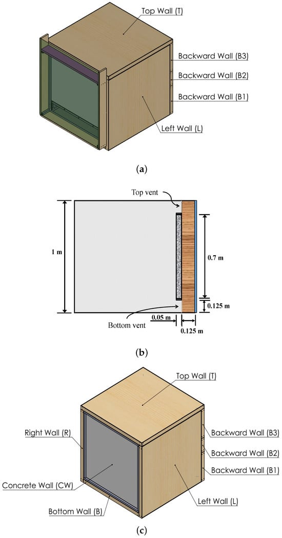
Figure 1.
Physical model of the test boxes. (a) TW test box, (b) Cross-section of the TW text box and (c) CF test box.
The facade of a building absorbs ≈ 70–80% () of the solar radiation it receives. Part of this absorbed energy is stored within the facade, while the remainder is transferred to the indoor air through conduction. In the case of the CF, it exchanges heat with the outdoor and indoor environments via convection and radiation. For the TW, heat is transferred to the indoor space through convection and radiation. Additionally, the TW transfers heat by convection and radiation to the air gap between the storage concrete wall and the glazing cover. This process causes the air in the channel to return to the indoor space of the test box at a higher temperature. The air transfers energy to the glazing cover within the TW channel, which also conducts heat. Finally, some energy is either lost or gained through convection and radiation at the external surface of the glazing cover, depending on the outdoor environmental conditions.
The top, bottom, right, left, and bottom walls of the test boxes were designed as composite walls, consisting of a medium-density fiberboard layer (0.0127 m), an extruded polystyrene layer (0.0254 m), and another medium-density fiberboard layer (0.0127 m). This configuration aimed to reduce heat transfer by conduction because the extruded polystyrene layer has a thermal conductivity of 0.0288 W/m·K. Further, to minimize radiative heat exchange in the indoor space a low-emissivity foil ( = 0.1) was applied to the inner surfaces of the composite walls. Each test box has an internal volume of 1 m × 1 m × 1 m.
Instrumentation
All composite walls were equipped with evenly distributed differential thermopiles to measure the average temperature difference between the internal and external surfaces. This temperature difference was used to determine the heat flux through the walls. Additionally, thermocouples were installed at the center of the inner surface of each wall (, , , , , , ) to serve as temperature references. All thermocouples and thermopiles used in the experiment were “T” type with a C uncertainty, PFA (perfluoroalkoxy) insulation, and special limit error (SLE). All thermocouples and anemometers were calibrated to set up the experiment. Moreover, the accuracy of the sensors was according to the intended measurements. Figure 2 shows the thermocouple distribution on a cross-section of the test boxes (, , , , ). Here, is positioned at the midpoint of the test box, while and are 25 cm vertically above and below , respectively. Similarly, and are located 25 cm horizontally to the east and west of , respectively. For the TW, thermocouples were installed on the glazing cover (, ) and at the middle of both the inlet and outlet vents (, ). In addition, a thermocouple () and an anemometer () were placed in the air-gap channel, 2 cm away from the CSW (Figure 2a). All sensors used in the experiment were connected to three 34901A acquisition cards, which were integrated into a 34972A data acquisition system. This system facilitated real-time monitoring and data recording on a connected PC, as shown in Figure 3, which depicts a schematic diagram of the experimental setup.
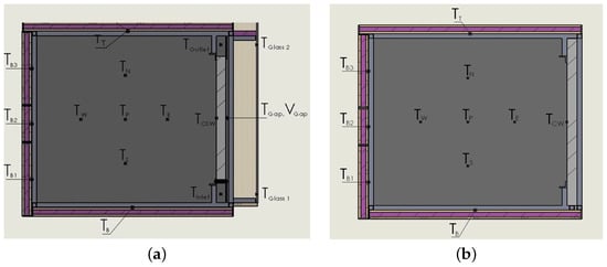
Figure 2.
Distribution of the thermocouples in the test boxes. (a) TW and (b) CF.
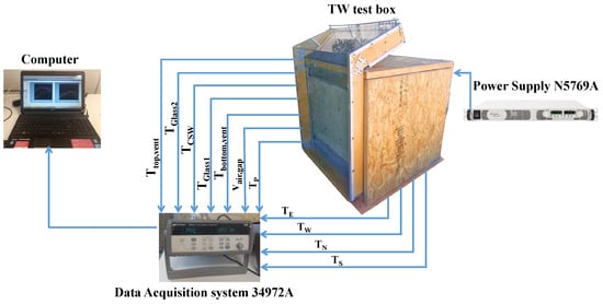
Figure 3.
Measured variables and equipment used to monitor the test boxes.
A programmable Power Supply N5769A (1500 W) was used to power the electrical resistance of the concrete wall (CF), with an uncertainty of 100 mV and 45 mA. For the thermal storage wall (TW), a programmable Power Supply TP10015 (1500 W) was used to supply energy to its electrical resistance, offering a reading accuracy of 500 mV and 450 mA. The power supplies were controlled based on the hourly average solar radiation calculated for a typical year. Figure 4 shows the test boxes: (a) TW and (b) CF. The experimental setup was installed at the Center for Scientific Research and Higher Education at Ensenada (CICESE), B.C., Mexico. Ensenada has a Mediterranean climate (Köppen classification: Csa), influenced by its coastal location along the Pacific Ocean. The Mediterranean conditions make it somewhat unique in Mexico, resembling climates more commonly found in southern California or parts of the Mediterranean basin. Climatic variables were monitored using a meteorological station equipped with a 16-bit data acquisition system, located N latitude and W longitude within the CICESE campus. Figure 5 shows a diagram that summarizes the procedure or methodology followed by the authors to develop the experimental tests using the test boxes.
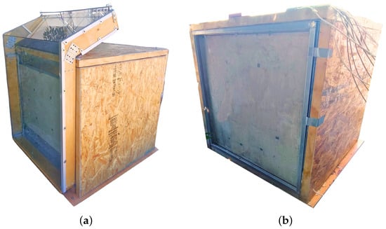
Figure 4.
Experimental test boxes. (a) TW and (b) CF.
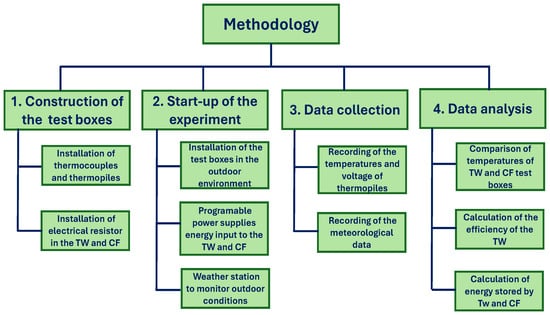
Figure 5.
Methodology diagram.
3. Results
This section shows and discusses the results regarding the temperature of the facades and the interior space, the energy accumulated on the storage wall, and the thermal efficiency. The experimental tests were carried out under winter conditions because this season provides the most challenging thermal environment to evaluate the ability of the Trombe wall to capture and store solar energy effectively. Since winter is typically when outdoor air temperatures are lower than in other seasons, assessing performance during this period is crucial for understanding its practical effectiveness in increasing the indoor air temperature of buildings. The first part of this section presents the TW thermal performance results from 3 to 7 February, corresponding to a sunny winter week. The second part of the results focuses on the thermal behavior of the TW on a sunny day (5 February) and on a cloudy day (24 February). In addition, the analysis of the energy stored in the TW and in a conventional concrete facade (CF) is presented.
3.1. Thermal Performance of the TW During a Sunny Week
This section presents the thermal behavior of the TW during a sunny winter week, from 3 to 7 February 2020. In this period, the ambient temperature oscillated between 8.3 and C and wind speeds between 0 and 2.8 m/s (Figure 6a). On the other hand, to simulate the solar radiation absorbed by the concrete walls, an electric power equivalent to the solar energy absorbed by a TW oriented to the south is induced (), which is shown in Figure 6b.
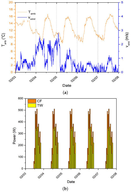
Figure 6.
Ambient conditions during a sunny winter week: (a) Ambient temperature () and wind velocity (), and (b) power induced in the facades for the sunny week.
Figure 7 shows the behavior of several temperatures in the TW text box: the temperature at the middle height of the storage wall (), the glass cover temperatures 5 cm away from the bottom () and the top (), the air temperature at the top vent (), and the air temperature at the bottom vent (). The figure indicates that the behavior of the temperatures in the TW is similar to that of the power induced in the TW, with peak values during the day and minimum values at night. The thermal behavior of the TW components is consistent across all five test days. Because the storage wall is the primary energy source for the test box, it exhibits higher temperatures than the air, glass covers, and other walls. The storage wall reached peak temperatures around C (). As air enters the channel between the storage wall and the glass cover, it is heated by the wall, which has a temperature higher than the bottom vent (). Consequently, the air rises through the channel as its density decreases and its temperature increases due to contact with the heated storage wall. As a result, the top vent temperature () becomes the second-highest, reaching peak values between C and C. During the day, the air circulating through the TW channel is heated, and can be up to C higher than . In contrast, at dawn, the temperature difference between and is nearly zero.
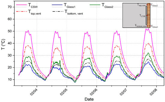
Figure 7.
Temperatures of several points in the TW.
The temperatures of and differ by up to C. The temperature is higher than because the top glass is in contact with warmer air. These results indicate that the glass temperatures in this system are not constant and vary with the height of the facade. The largest temperature fluctuations for both and were observed on 4 February, coinciding with the highest recorded wind speed () on that day (Figure 6a). Additionally, although the heating values are similar across the monitored days, 7 February exhibits the highest temperatures in the TW. This is due to the combination of the highest ambient temperature () and lower wind speeds (), resulting in reduced heat losses. This effect is further evidenced by the thermal efficiency calculations, which reflect the amount of energy retained in the air circulating through the TW.
The thermal efficiency () is defined as the ratio of the energy gained by the air in the TW, denoted as , to the total amount of solar radiation received. In this context, the solar radiation is represented by the induced power [24]. Thus, the thermal efficiency can be expressed as follows:
where was obtained from the average air speed () measured by the anemometers at the vents of the TW, the cross-sectional area of the vents (), the and the , in such a way that it is expressed as
Figure 8 shows the hourly thermal efficiency () of the TW during the hours of solar radiation. As noted earlier, 7 February exhibits the highest thermal efficiency, reaching a peak value of 84%. In contrast, the maximum on 4 February is lower than that of the other days, with a value of 62%. The lower thermal efficiency observed on 4 February can be attributed to the high wind speeds (), which increase heat losses to the outside, thereby reducing the amount of energy gained by the air.
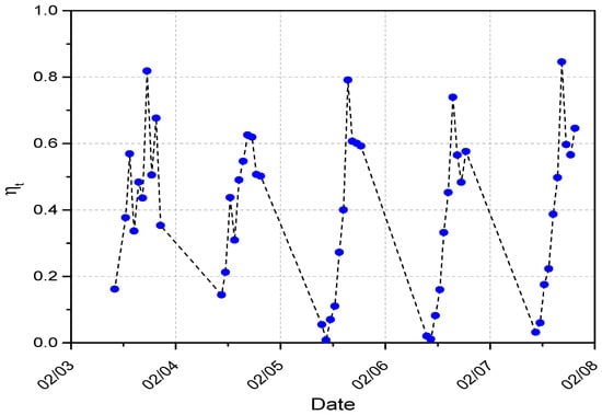
Figure 8.
Hourly thermal efficiency of the TW.
The thermal behavior of the TW significantly influences the temperature of the air within the indoor space of the test box (). In this study, the air temperature was measured at five points inside the test box (, , , , ), as shown in Figure 2a. These points were selected to examine the temperature distribution caused by natural convection. Figure 9 shows the behavior of , , , , and , along with the ambient temperature (). The temperature distribution within the module follows a natural convection pattern, with the air in the upper region exhibiting the highest temperatures (), while the air in the lower region shows the lowest temperatures (). This temperature gradient is most pronounced during the day, with a difference of up to 7.6 °C, and becomes negligible during the night and early morning. Furthermore, the temperature differences between , , and are minimal, indicating that the temperature variation in the horizontal direction at the mean height of the cavity is insignificant. This small variation closely resembles the behavior observed in natural convection within a differentially heated cavity filled with air.
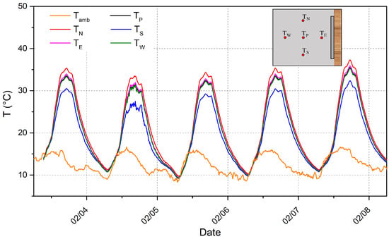
Figure 9.
Behavior of the indoor air temperature and ambient temperature.
The average temperature of the indoor space in the module () is influenced by climatic variables such as ambient temperature (), wind speed (), and absorbed solar radiation, which, in this study, is represented by the electric power. To assess the stability of the temperature inside the module due to the presence of the TW, the thermal load leveling (TLL) was calculated. This parameter is defined as the difference between the maximum and minimum temperatures inside the module ( and ), divided by their sum [25]:
where the values of and were determined from the average temperature of the interior space of the module ( = ( + + + + )/5). Equation (3) indicates that the numerator indicates the degree of fluctuation of the interior temperature and the denominator the basic value of such fluctuation. Therefore, the TLL value was calculated for each day (Table 1).

Table 1.
Thermal load leveling (TLL) during a sunny week.
A TLL interval between 0.41 and 0.55 was obtained for the TW test box. Therefore, a reduced variation interval between the TLL values is observed. However, the highest TLL values correspond to the days with the lowest in the early morning, at which time the absorber wall has released all the heat stored during the day and, therefore, the is similar to . Finally, it is worth mentioning that the literature indicates that as the thickness of the storage wall increases, the TLL in the system decreases, and is valid only for absorbed walls with high thermal mass, which are desirable for TW. Also, it is worth mentioning that the mass production of housing in Mexico uses concrete as the main material due to its thermophysical properties, mainly the concrete formwork system with 10 cm of reinforced concrete [26,27]. For example, for a semi-transparent photovoltaic thermal Trombe wall with a thickness of 0.4 m, Taffesse et al. [25] reported a TLL of up to 0.02.
3.2. Thermal Behavior of the TW During a Sunny Day and a Cloudy Day
This section presents the thermal behavior of the TW on two days: a sunny winter day (5 February 2020) and a cloudy winter day (24 February 2020) in Ensenada, B.C., Mexico. Figure 10 shows the ambient temperature (), wind speed (), and power at the TW for both days. On the cloudy day, the is slightly higher than on the sunny day, with ranging from 8.3 to C on the sunny day and from 12.6 to C on the cloudy day. In terms of power, the sunny day achieves a maximum value of 357 , while the cloudy day reaches 219.8 . These values correspond to the solar radiation absorbed by a south-facing wall.
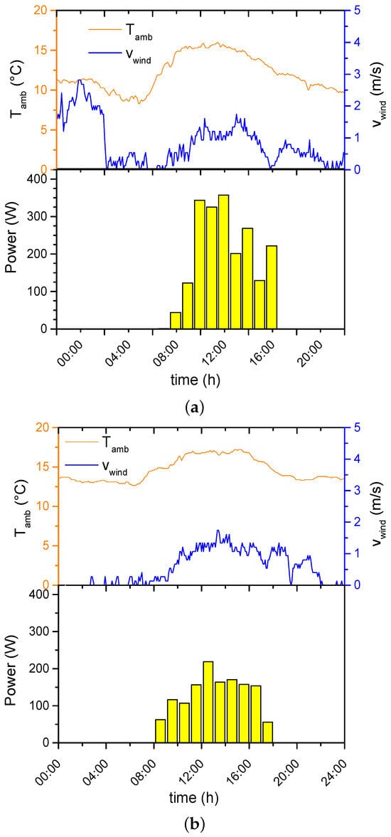
Figure 10.
Ambient temperature (), wind velocity (), and power at the TW for (a) the sunny day and for (b) the cloudy day.
Figure 11 shows the behavior of the , the indoor air temperature in the center of the module (), the air temperature in the TW vents ( and ), and the for (a) sunny day and (b) cloudy day. The figure shows that the value of is directly proportional to the energy the TW receives. Consequently, is up to C higher on the sunny day compared to the cloudy day. The energy received by the TW affects the heating potential of the system, which can be observed from the temperature difference between the air in the upper and lower vents. The maximum value of is similar for both days; however, on the sunny day, the temperature difference ( ) increases by up to C, whereas on the cloudy day, the increase is only C. Additionally, the indoor air temperature () reaches peak values of up to C on the sunny day, compared to C on the cloudy day, indicating a temperature difference of approximately C between the two days. This suggests that both the energy absorbed by the wall and the ambient temperature () significantly influence . In general, the differences in the variables compared on both days were not significant, which is due to both the power values, which were higher on the sunny day, and due to the values of , which were slightly smaller on the cloudy day. Also, it is worth mentioning that the TLL for the sunny day is 0.55 and 0.31 for the cloudy day; such values indicate greater stability in the indoor air temperature during the cloudy day because it presented fewer temperature oscillations.
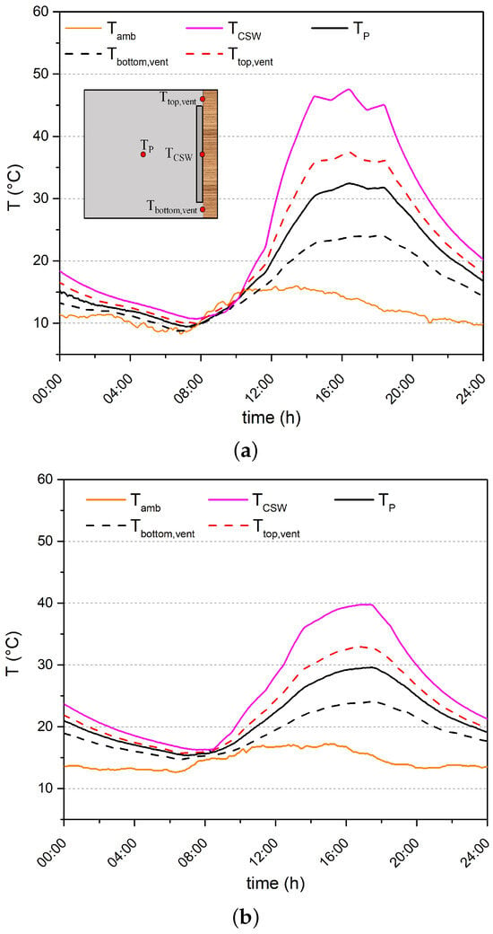
Figure 11.
Thermal behavior of the TW test box for (a) the sunny day and for (b) the cloudy day.
3.3. Stored Energy in the TW and the CF
The temperature of the walls and their properties were used to determine the amount of energy stored by the TW and the conventional facade (CF). The stored energy is determined from the energy balance equation:
The stored energy indicates the difference between the energy received by the wall () and the energy released () [28]. Therefore, the stored energy is determined as a function of the variation in the hourly average temperature and is expressed as follows:
where = 1 h, and the is calculated by an arithmetic average of the recorded during the .
Figure 12 illustrates the hourly stored energy, the air temperature behavior at the midpoint of both test modules ( and ), as well as the ambient temperature () and wind velocity (). Positive values of hourly stored energy occur when the facades are receiving energy, indicating that the energy input () is greater than the energy output () as described by Equation (4). On the contrary, from sunset until early morning, negative values are observed, indicating that is less than . The peak value of coincides with the moment when the facades begin releasing energy, while the minimum value of corresponds to the time when energy absorption begins. The hourly stored energy of the CF shows a similar trend to that of the TW, although the CF stores slightly more energy, with a maximum difference of up to 233.5 kJ/h. This difference is due to the larger volume of the CF, which increases its storage capacity. However, the TW module consistently exhibits higher indoor air temperatures (9.4 ≤ C), compared to the CF (8.1 ≤ C), which shows more pronounced fluctuations, particularly on 4 February 2020 when wind velocities () were higher. This suggests that, although the CF stores more energy, it also releases a significant amount to the external environment, making it more sensitive to changes in . In contrast, the TW reduces heat losses to the outside due to its glass cover, making less sensitive to fluctuations in . Despite storing less energy, the TW is more effective for transferring heat to the indoor air compared to the CF. There are also some shortcomings associated with using TW. The thermal behavior observed in the TW might increase the cooling load in the summer. To prevent overheating in the summer, it is suggested to incorporate passive cooling strategies, such as natural ventilation or shading devices. Moreover, Trombe walls should face south for optimal performance, which may not be feasible in all buildings or locations.
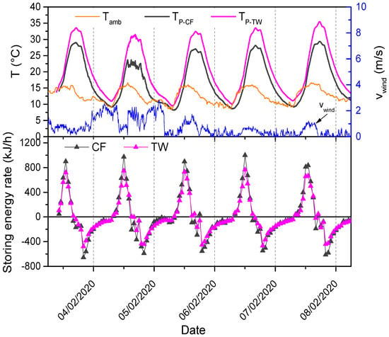
Figure 12.
Hourly stored energy and indoor air temperature of the TW and the CF.
4. Conclusions
This research presented the construction and experimental thermal evaluation of two test boxes designed to represent a room space, one coupled to a Trombe wall (TW) and the other one coupled to a concrete facade (CF) facade. Experiments were conducted under winter conditions in Ensenada, Baja California, characterized by a semi-arid Mediterranean climate. This study evaluated the thermal performance of the TW during a sunny week in winter, as well as on individual sunny and cloudy days. Additionally, a comparative analysis was performed to assess the stored energy and indoor air temperature behavior associated with each façade type. The main conclusions of this research are as follows:
- The glazing cover in the TW presents a nonuniform thermal behavior, with the temperature on the top region being up to C higher than in the bottom region on a sunny winter day. The results also indicate that the most significant oscillations of glazing temperature occur on windy days. Thus, it can be concluded that the thermal performance of the TW is mainly affected by the wind velocity.
- The TW can increase the air temperature through its channel up to C, which yields a maximum thermal efficiency of 84% during the sunny winter day. On the other hand, the maximum thermal efficiency during a windy day with solar radiation similar to a sunny day is up to 64%.
- The comparison between the results from the sunny day and the cloudy day revealed a difference up to C in the maximum indoor air temperature, which corresponds to values of C for the sunny day and C for the cloudy day. Additionally, the thermal load leveling (TLL) was 0.55 for the sunny day and 0.31 for the cloudy day. These findings indicate that higher solar radiation contributes to improved thermal stability of the indoor air.
- It was found that the TW test module shows the highest indoor air temperature values (9.4 ≤ C) regarding the CF-test module (8.1 ≤ C) because the cover glazing of the TW reduces heat losses to the outdoor environment. We also observed that the indoor air temperature on the CF-test module is very close to the ambient temperature at night and even below the ambient temperature during the morning.
Finally, it is concluded that TW can improve the thermal behavior of buildings under winter conditions in Ensenada, B.C., Mexico. The thermal behavior observed in the TW might increase the cooling load in the summer. To prevent overheating in the summer, passive cooling strategies, such as natural ventilation or shading devices, should be incorporated. Moreover, TW should face south to have a good thermal performance, which may not be feasible in all buildings. Therefore, the authors are studying further experiments to observe the TW thermal performance in summer conditions of Ensenada. Further, the authors are examining the possibility of isolated configurations to avoid an adverse effect of the TW on summer conditions and propose a modified TW coupled to a solar chimney configuration in future works.
Author Contributions
Conceptualization, I.H.-P. and I.Z.-G.; writing—original draft preparation, I.H.-P., Á.R.-A., D.S.-C., I.H.-L. and B.K.; writing—review and editing, I.H.-P., Á.R.-A., D.S.-C., I.H.-L. and B.K. All authors have read and agreed to the published version of the manuscript.
Funding
This work was financially supported by Consejo Nacional de Humanidades, Ciencia y Tecnología, CONAHCYT-Mexico, project PN-2017-5658 (module for evaluating passive ventilation and heating systems for energy-saving purposes in buildings).
Data Availability Statement
The original contributions presented in this study are included in the article. Further inquiries can be directed to the corresponding author.
Acknowledgments
The authors acknowledge CONAHCYT-Mexico for the support given through the System of National Researchers program (Sistema Nacional de Investigadoras e Investigadores, SNII). This work is dedicated to the memory of our mentor and friend J. Xamán. Rest in peace dear friend, you will forever stay in all of our hearts.
Conflicts of Interest
The author declare no conflicts of interest.
References
- World Energy Balances 2020 Edition; Technical Report; International Energy Agency: Paris, France, 2020.
- Rosas-Flores, J.; Rosas-Flores, D. Potential energy savings and mitigation of emissions by insulation for residential buildings in Mexico. Energy Build. 2020, 209, 109698. [Google Scholar] [CrossRef]
- Miao, J.; Tian, M.; Qu, L.; Zhang, X. Flexible, transparent and conductive wearable electronic skin based on 2D titanium carbide (MXene) ink. Carbon 2024, 222, 118950. [Google Scholar] [CrossRef]
- He, Y.; Guo, S.; Zuo, X.; Tian, M.; Zhang, X.; Qu, L.; Miao, J. Smart Green Cotton Textiles with Hierarchically Responsive Conductive Network for Personal Healthcare and Thermal Management. Acs Appl. Mater. Interfaces 2024, 16, 59358–59369. [Google Scholar] [CrossRef] [PubMed]
- Liu, Y.; Feng, W. Integrating passive cooling and solar techniques into the existing building in South China. Adv. Mater. Res. 2012, 368–373, 3717–3720. [Google Scholar] [CrossRef]
- Hu, Z.; He, W.; Ji, J.; Zhang, S. A review on the application of Trombe wall system in buildings. Renew. Sustain. Energy Rev. 2017, 70, 976–987. [Google Scholar] [CrossRef]
- Briga-Sá, A.; Martins, A.; Boaventura-Cunha, J.; Lanzinha, J.C.; Paiva, A. Energy performance of Trombe walls: Adaptation of ISO 13790:2008(E) to the Portuguese reality. Adv. Mater. Res. 2014, 74, 111–119. [Google Scholar] [CrossRef]
- Hordeski, M.F. Dictionary of Energy Efficiency Technologies; Fairmont Press: Fairmont, WV, USA, 2004. [Google Scholar]
- Wang, D.; Hu, L.; Du, H.; Liu, Y.; Huang, J.; Xu, Y.; Liu, J. Classification, experimental assessment, modeling methods and evaluation metrics of Trombe walls. Renew. Sustain. Energy Rev. 2020, 124, 109772. [Google Scholar] [CrossRef]
- Zalewski, L.; Chantant, M.; Lassue, M.; Duthoit, B. Experimental thermal study of a solar wall of composite type. Energy Build. 1997, 55, 8–17. [Google Scholar] [CrossRef]
- Zalewski, L.; Joulin, A.; Lassue, S.; Dutil, Y.; Rousse, D. Experimental study of small-scale solar wall integrating phase change material. Sol. Energy 2012, 86, 208–219. [Google Scholar] [CrossRef]
- Abbassi, F.; Dimassi, N.; Dehmani, L. Energetic study of a Trombe wall system under different Tunisian building configurations. Energy Build. 2014, 80, 302–308. [Google Scholar] [CrossRef]
- Dimassi, N.; Dehmani, L. Experimental heat flux analysis of a solar wall design in Tunisia. J. Build. Eng. 2016, 8, 70–80. [Google Scholar] [CrossRef]
- Dimassi, N.; Dehmani, L. Performance comparison between an improved and a classical Trombe wall: An experimental study. J. Build. Phys. 2017, 40, 372–395. [Google Scholar] [CrossRef]
- Rabani, M.; Rabani, M. Heating performance enhancement of a new design trombe wall using rectangular thermal fin arrays: An experimental approach. J. Energy Storage 2019, 24, 100796. [Google Scholar] [CrossRef]
- Baïri, A.; Martín-Garín, A.; Adeyeye, K.; She, K.; Millán-García, J. Enhancement of natural convection for improvement of Trombe wall performance. An experimental study. Energy Build. 2020, 211, 109788. [Google Scholar] [CrossRef]
- Abbassi, F.; Dehmani, L. Experimental and numerical study on thermal performance of an unvented Trombe wall associated with internal thermal fins. Energy Build. 2015, 105, 119–128. [Google Scholar] [CrossRef]
- Qi, X.; Wang, J.; Wang, Y. Influence of a Built-in Finned Trombe Wall on the indoor thermal environment in cold regions. Energies 2024, 17, 1874. [Google Scholar] [CrossRef]
- Hu, Z.; Zhang, S.; Hou, J.; He, W.; Liu, X.; Yu, C.; Zhu, J. An experimental and numerical analysis of a novel water blind-Trombe wall system. Energy Convers. Manag. 2020, 205, 112380. [Google Scholar] [CrossRef]
- Islam, N.; Irshad, K.; Zahir, M.H.; Islam, S. Numerical and experimental study on the performance of a Photovoltaic Trombe wall system with Venetian blinds. Energy 2021, 218, 119542. [Google Scholar] [CrossRef]
- Zelama, A.; Licholai, L.; Krasón, J.; Miasik, P.; Mikusova, D. The Effects of Using a Trombe Wall Modified with a Phase Change Material, from the Perspective of a Building’s Life Cycle. Energies 2024, 16, 7689. [Google Scholar]
- Mezrhab, A.; Rabhi, M. Modeling of the thermal transfers in an enclosure of the Trombe wall type. Thermodyn. Anal. Renew. Energy 2008, 6, 9–14. [Google Scholar]
- Hernández-Pérez, I.; Xamán, J.; Macías-Melo, V.; Aguilar-Castro, K.M.; Zavala-Guillén, I.; Hernández-López, I.; Simá, E. Experimental thermal evaluation of building roofs with conventional and reflective coatings. Energy Build. 2018, 158, 569–579. [Google Scholar] [CrossRef]
- Zhou, L.; Huo, J.; Zhou, T.; Jin, S. Investigation on the thermal performance of a composite Trombe wall under steady state condition. Energy Build. 2020, 214, 109815. [Google Scholar] [CrossRef]
- Taffesse, F.; Verma, A.; Singhand, G.N.; Tiwari, S. Periodic modeling of semi-transparent photovoltaic thermal-trombe wall (SPVT-TW). Sol. Energy 2016, 135, 265–273. [Google Scholar] [CrossRef]
- Becerra-Santacruz, H.; Lawrence, R. Evaluation of the thermal performance of an industrialised housing construction system in a warm-temperate climate: Morelia, Mexico. Build. Environ. 2016, 107, 135–153. [Google Scholar] [CrossRef]
- Bacelis, G.; Martínez-Torres, K.; Ruíz-Torres, R.P. Validation of thermal performance during winter season in a low-income housing model. Vivienda Comunidades Sustentables 2024, 15, 63–80. [Google Scholar] [CrossRef]
- Rabani, M.; Kalantar, V.; Dehghan, A.; Faghih, A.K. Experimental study of the heating performance of a Trombe wall with a new design. Sol. Energy 2015, 118, 359–374. [Google Scholar] [CrossRef]
Disclaimer/Publisher’s Note: The statements, opinions and data contained in all publications are solely those of the individual author(s) and contributor(s) and not of MDPI and/or the editor(s). MDPI and/or the editor(s) disclaim responsibility for any injury to people or property resulting from any ideas, methods, instructions or products referred to in the content. |
© 2025 by the authors. Licensee MDPI, Basel, Switzerland. This article is an open access article distributed under the terms and conditions of the Creative Commons Attribution (CC BY) license (https://creativecommons.org/licenses/by/4.0/).