Review

Ammonia Combustion: Internal Combustion Engines and Gas Turbines

Department of Mechanical Engineering, School of Engineering, University of Birmingham, Birmingham B15 2TT, UK
*
Author to whom correspondence should be addressed.
Energies 2025, 18(1), 29; https://doi.org/10.3390/en18010029
Submission received: 20 November 2024 / Revised: 14 December 2024 / Accepted: 19 December 2024 / Published: 25 December 2024
(This article belongs to the Section I1: Fuel)

Abstract

:
The quest for renewable energy sources has resulted in alternative fuels like ammonia, which offer promising carbon-free fuel for combustion engines. Ammonia has been demonstrated to be a potential fuel for decarbonizing power generator, marine, and heavy-duty transport sectors. Ammonia’s infrastructure for transportation has been established due to its widespread primary use in the agriculture sector. Ammonia has the potential to serve as a zero-carbon alternative fuel for internal combustion engines and gas turbines, given successful carbon-free synthesis and necessary modifications to legacy heat engines. While its storage characteristics surpass those of hydrogen, the intrinsic properties of ammonia pose challenges in ignition, flame propagation, and the emissions of nitrogen oxides (NOx) and nitrous oxide (N2O) during combustion in heat engines. Recent noteworthy efforts in academia and industry have been dedicated to developing innovative combustion strategies and enabling technologies for heat engines, aiming to enhance efficiency, fuel economy, and emissions. This paper provides an overview of the latest advancements in the combustion of neat or high-percentage ammonia, offering perspectives on the most promising technical solutions for gas turbines, spark ignition, and compression ignition engines.

1. Introduction

For many decades, fossil fuels have been used as the primary source of power generation, resulting in by-combustion products, mainly CO2 emissions, that have contributed hugely to global warming. Despite some measures taken to improve combustion efficiency, most importantly, urgent actions are required to combat climate change. Countries have pledged to the Paris Agreement’s goals and are committed to achieving carbon neutrality by 2050, emphasizing the immediate need for carbon-zero fuel solutions. The Paris Agreement established a global warming restriction to below 2 °C above pre-industrial levels, aiming to cap it at 1.5 °C at the UN climate change conference [1]. Hydrogen and ammonia are both potential carbon-free candidates. However, these fuels present unique challenges that must be addressed for widespread adoption. Hydrogen, with its low ignition energy, wide flammability range, and low volumetric energy density (2.9 MJ/L at 70 MPa) poses a concern mainly in transportation and storage. Ammonia is known as a carbon-free fuel, with established infrastructure because of its use in agriculture, and its high hydrogen density (hydrogen carrier) and relatively simple storage compared to compressed hydrogen make it more attractive as an alternative fuel for decarbonization in the transport sector, mainly heavy-duty transport, as the need for network pipelines is already met and the economics would be less of an issue for its transportation and storage [2]. Ammonia’s unique properties, such as the absence of CO2 emissions during combustion and a high energy density (7.1 MJ/L), include the fact that it can potentially undergo dual strategies with more reactive fuels like hydrogen to improve its combustion stability in automotive engines, making it a beacon of hope for a sustainable future [3,4,5]. Table 1 summarises ammonia properties and highlights the combustion characteristics of ammonia as a potential alternative fuel along with conventional fuels.
Despite ammonia’s advantages, it also encounters challenges such as flame stability and low ignition because of ammonia’s high auto-ignition temperature and low flame speed, causing a problem in achieving combustion efficiency during combustion. Ammonia’s inherent toxicity and corrosivity present health, environmental, and infrastructure requirement risks during transportation, handling, and accidental leaks. Additionally, ammonia combustion results in NOx production and ammonia slip, necessitating advanced treatment systems such as selective catalytic reduction (SCR) to comply with the safety and environmental automotive emission regulation standards. Ammonia holds excellent promise for decarbonization; ammonia’s safe and efficient use will necessitate addressing these limitations through technological innovations, infrastructure, and policy development.
Ammonia can be produced through various methods, such as steam reforming from natural gas, naphtha, heavy fuel oil, coal, and refinery gas [10]. These methods have resulted in higher greenhouse gas emissions and energy consumption [11], leading to more interest in alternative methods of production where Haber–Bosch and solid-state ammonia synthesis processes are currently the most used. Conventionally, diesel and gasoline fuels have been widely used for power generation but are associated with challenges such as CO2 emissions and other pollutants causing environmental impact [12,13]. Therefore, adopting ammonia fuel provides a revolutionary approach and a promising way to mitigate these hazardous emissions and reduce carbon footprint [14,15]. Ammonia has been recognized as an alternative fuel for power generation and propulsion, particularly in the maritime and heavy-duty applications. In these sectors, green ammonia distribution and synthesis are primarily investigated, whereas light-duty applications where electric batteries and hydrogen cells are the focus due to their ease of integration and higher efficiency. Converting existing gasoline or diesel engines to run on ammonia rather than manufacturing new ones appears technically feasible but presents challenges such as cost and the complexity of the engineering related to the design modifications and material replacements. This conversion comes with technical obstacles that, if overcome, will enable the efficient use of ammonia in a conventional generator [16,17]. Considering the extensive global inventory of internal combustion engines (ICEs) and gas turbines (GTs), direct ammonia combustion with minimal emissions has a substantial impact on the energy transition, offering significant energy, space, and cost savings compared to the alternative of ammonia decomposition back to hydrogen for various applications. The direct combustion of ammonia in ICEs and GTs poses challenges attributed to ammonia’s intrinsic properties, such as high ignition energy, a narrow flammability limit, slow laminar burning velocity, cooling effect, corrosion effect, and the emission of NOx and N2O when air serves as the oxidant [18,19]. This review offers an overview of the latest research and developments focusing on emerging ICE and GT combustion approaches and enabling technologies investigated in experimental studies. Special attention is directed towards neat ammonia combustion and hydrogen-assisted methods in the pursuit of achieving carbon-neutral combustion.

2. Ammonia Combustion in Internal Combustion Engines

2.1. Ammonia Combustion

The application of ammonia-fuelled ICEs was seen during World War II due to diesel oil scarcity in Europe. Recently, major marine engine manufacturers (MAN, WinGD, and Wartsila) are developing new ammonia-fuelled models for both low-speed, two-stroke [20,21], and medium-speed, four-stroke engines [22]. Japan’s IHI Power Systems made significant strides in four-stroke engines, successfully co-firing 80% ammonia in land-based trials [23]. In the UK, Mahle Powertrain focuses on ammonia-fuelled heavy-duty engines for the mining and construction industries [24]. Canadian company Hydrofuel modifies high-power vehicle engines for power generation [25]. Notably, Toyota and their Chinese partner GAC started to develop four-stroke engines for passenger cars in 2023 [26]. Reviews documenting the advancements of internal combustion engines fuelled by ammonia [27,28], have been consistently published.
Ammonia’s elevated auto-ignition temperature demands high ignition energy in spark ignition (SI) engines. However, engine trials using neat ammonia showed inferior performance due to slow flame propagation. Successful combustion required proper mixing and advanced ignition timing in addition to higher spark energy through ignition system modification. A study [29] on a four-stroke SI engine using neat ammonia revealed the cylinder temperature’s greater impact on ignition delay than pressure.
In most literature, a secondary fuel is used as a promoter. In the case of the SI engine, gasoline was first used as a promoter for the combustion of ammonia in a conventional engine. Gasoline is there to boost ammonia ignition with its higher cetane number, leading to a shorter ignition delay time. A certain amount of gasoline was therefore required for combustion. In the same context, studies on ammonia and gasoline dual-fuelled SI engines were conducted by Ryu et al. [30]. Their study investigated ammonia combustion characteristics and emissions in an SI engine using gasoline port injection as a baseline (0.6 kW power). The finding showed that the total engine power increased to 2.7 kW when ammonia injection timing and duration were advanced to 370 BTDC and 22 ms, respectively. While the ammonia peak pressure was slightly lower than gasoline alone due to ammonia’s slow flame speed, the brake specific energy consumption (BSEC) stayed the same with gasoline-only operation, as can be seen in Figure 1. They reported that the use of ammonia resulted in CO emissions and an increase in NOx and HC emissions, with ammonia slipping because of incomplete combustion [30].
In a different study [31], Grannel et al. demonstrated the feasibility of a vehicle based on the combustion of a 70% ammonia and 30% gasoline (lower heating value) mixture to overcome the high auto-ignition values of ammonia. Recently, an experimental study using an SI engine was conducted by Kurien et al. to investigate the effect of ammonia energy fractions on combustion stability and performance in a dual-fuelled (NH3/CH4) single-cylinder SI engine [32]. Their results showed that the fuel mixture’s lower heating value and flame propagation speed decreased with ammonia share (0–60% at 8 Nm load) increase, leading to an engine performance reduction and more significant combustion variability (1.36–14.9% COV of IMEP) [32]. On the other hand, performance, flame speed, and combustion stability (COV reduced to 4.3%) improved with an increase in the load to 16 Nm. Overall, to achieve cleaner fuel and less hydrocarbon emission, their study suggested that an ammonia blend can be optimized at higher loads.
With the objective to combat climate change and reduce CO2 emissions, most studies have started using hydrogen as an ammonia fuel promotor [33], which was commonly used to enhance ammonia combustion. Findings showed 5–10% hydrogen in a lean mixture achieved the highest indicated efficiency (39%) [34]. Recent research conducted in current SI engines proved that ammonia could burn with small quantities of H2 (around 5–10%vol.) or even without H2 at only a compression ratio of around 10:1 in a full load for forthcoming hybrid vehicles or range extender systems [35]. Higher hydrogen fractions (40–60%) increased heat release rate, raising heat loss and lowering efficiency. Elevated compression ratios (CRs) contributed to enhanced engine efficiency, facilitated by the excellent anti-knock properties of NH3/H2 blends [36]. Pyrc et al. solidified the effect of CR with an experimental investigation at variable CR SI engine dual-fuelled ammonia–hydrogen (energy shares ranging from 0% to 70%) combustion [37]. The findings revealed that ammonia alone led to ignition failures or delayed combustion at CRs equal to eight and ten. For CRs eight and ten, as shown in Figure 2, ignition instability is resolved, and engine performance and combustion stability have improved along with an IMEP increase when 12% hydrogen is introduced. The results also proved that higher hydrogen shares increased NO emissions for both compression ratios.
In earlier trials with NH3/H2 blends in SI engines (e.g., 80% vol. NH3—20% vol H2) [38], NO emissions (3000–5000 ppm) were comparable to gasoline, but the peak shifted to a higher excess air ratio (λ = 1.35) due to fuel-bond NO formation. A recent study [29] showed NOx rising from <1000 ppm at λ = 1 to 5000–6000 ppm at λ = 1.3 lean burn before dropping again. Among NOx emissions from NH3/H2 combustion, about 3–4% of NO2 emission was greater than that of <2% in conventional gasoline engines, likely due to nitrogen’s presence in ammonia [38]. While an increased hydrogen and compression ratio improved combustion [39], higher temperatures increased NOx. A trade-off between NOx and NH3, as well as N2O emission (GWP 298 times CO2), is shown in Figure 3. N2O formation starts below 1350 K, until 650 K, possibly from unburnt ammonia in crevices at intermediate temperatures and excess air [29].
Hydrogen, a crucial promoter for ammonia combustion, can be produced onboard through ammonia decomposition, eliminating the need for a secondary hydrogen storage system. The endothermic decomposition reaction (ΔH°= 92 kJ/mol) is influenced by various monometallic (e.g., Ru, Ni, etc.) and bimetallic catalysts (e.g., Ni–Pt) [36]. In an early attempt, NOx emission reduction and combustion efficiency improvement were achieved in an SI engine with a catalyst with 2% Ru on alumina pellets [40]. An ammonia electrolyte cell (AEC) was assessed for onboard ammonia cracking [41]. The latest study of an onboard ammonia cracker showcased stable combustion in a four-stroke SI engine with a hydrogen fraction of 12.6 to 66.1 mol%, derived from autothermal reforming of ammonia [42]. It is still the early stage of studies covering ammonia decomposition, combustion, and exhaust aftertreatment.
Another advancement in research has been highlighting ammonia combustion potential using combustors for decentralized power and small-scale systems. Kim and Kwon [43] developed a micro-reforming system integrated with a heat-recirculating micro combustor to produce hydrogen from ammonia to burn hydrogen-added ammonia air mixtures using a recirculating combustor as a feature and using a ruthenium-catalysed micro-reformer. The findings reveal the important role of the ruthenium-catalyst in enhancing heat transfer. This system achieves a significant hydrogen production rate of 5.4 W, an ammonia rate of conversion of 97%, and an overall efficiency of 10.4%, and maintains NOx emission at 158 ppm at optimal conditions, providing effective combustion efficiency and stability via inlet NH3-H2- air mixture velocity, and equivalence ration optimization [43]. Zhao et al. [44] investigated an ammonia/methane-fuelled micro-thermal photovoltaic combustion system. The findings reveal that, at a specific inlet velocity, the system achieved optimal performance with an electrical power output of 6.9 W and energy efficiency of 5.85%. This was accomplished using the methane mole fraction (0.9) as the burning velocity and power output booster and quartz; micro-combustion material being a significant aid for CO emissions reduction [44]. Both study ammonia feasibility as a clean fuel used in reforming and burning with a methane blend, improving combustion efficiency and stability for power generation.
Recently, prechamber turbulent jet ignition (TJI) was used to aid ammonia combustion by employing a spark plug in a prechamber with multiple jet holes, accelerating the jet flame into the main engine cylinder. A numerical work at 3 MPa and 800 K predicted higher OH, O, and HNO radicals with a higher equivalence ratio in lean burn, leading to reduced NOx [45]. In an optical study [46], at 0.8–1.1 MPa and 500 K, TJI outperformed direct SI, reducing ignition delay by 60% and combustion duration by 47–77%, in turn, resulting in a rapid pressure rise rate. A study involving gaseous ammonia and air injection into the prechamber (see Figure 4) revealed improved combustion stability [47], allowing a spark timing lag from 40–45° to 22–28 °CA BTDC and reducing both NOx emissions and NH3 slip. Key factors influencing TJI performance are spark location, the geometry of prechamber and jet flame orifices, active pilot fuel injection, and prechamber scavenging (exhaust gas recirculation) [18].
Other ignition strategies were explored, including multiple spark plugs [48], glow plug-assisted prechamber TJI [49], and plasma-assisted combustion (PAC) [27,50]. PAC stimulates the direct decomposition of ammonia to hydrogen at a low-temperature threshold (<450 °C), outperforming thermal decomposition. Ammonia ignition delay decreased with rising pulsation frequency and pulse number of PAC [51], attributed to the accumulation of the reactive radical pool (e.g., OH*, H*, and O*). PAC generally extends lean the blowoff limits of ammonia flames, reducing NOx emissions, although no experimental engine uses PAC yet.
Ammonia’s low flame speed and high ignition temperature also make it a poor candidate for traditional SI engines such as Otto-cycle and Atkinson-cycle engines, which rely on a spark plug and on fuel that ignites easily and burns quickly compared to ammonia, providing insufficient energy to initiate combustion. CI engines are better equipped to burn ammonia, as they can produce the high pressures and temperatures necessary for ammonia to self-ignite, overcoming its poor spark-ignition characteristics. Hence, engine manufacturers are concentrating on CI applications for ammonia, possibly in conjunction with a dual-fuel strategy, where a small amount of diesel or hydrogen is used to overcome ignition issues and optimize combustion. Incorporating ammonia into CI engines also poses challenges, primarily due to the initiation of combustion through fuel auto-ignition. In most studies, diesel was still used as a pilot fuel, and ammonia was introduced via intake port injection [52]. Niki et al. investigated ammonia gas port injection into an intake manifold of a 1.1 L single-cylinder CI engine adjusted with a selective catalytic reduction (SCR) system to reduce NOx and unburned NH3 emissions [53]. The findings revealed decreased compression and peak pressures, extended ignition delay, and increased unburned NH3 emissions as the ammonia supply increased. This investigation concluded that ammonia could be viable in compression-ignition engines. However, optimized injection strategies and SCR systems to manage NOx and unburned ammonia can achieve effective emissions control. In a later study [54], Niki et al. focused on emission management. They found that reduced N2O emissions and improved ammonia combustion were achieved by increasing combustion temperature and using advanced diesel injection strategies. A recent study on a 9.5 L four-stroke CI engine explored up to 90% ammonia injection by heat fraction [55]. At low–medium ammonia addition (0–40%), increasing premixed NH3/air concentration enhanced the first premixed combustion heat release peak with more OH*. At higher ammonia percentages (80–90%), the overall heat release profile was suppressed due to slow flame speed-induced late combustion. Pilot fuel injection strategies were extensively explored, such as pilot n-heptane injection and up to 98% NH3 port injection [56], pilot diesel and 71–91% NH3 port injection [57], pilot diesel and 50% NH3 port injection [58], and split pilot diesel injections [59]. Advanced pilot diesel injection (around 25–40°CA BTDC) optimises reactivity-controlled compression ignition (RCCI) and maximises indicated efficiency. Due to the complexity of combustion and variety of test engine geometries, optimal strategies for reducing NOx emissions and NH3 slip are still being explored. Another study explored ammonia in diesel in a dual-fuel CI engine [60]. Experimental findings revealed that 84.2% of the engine’s input energy can be provided by ammonia while increasing indicated thermal efficiency (ITE). Carbon based emissions such as CO2, CO, and particulate matter (PM) are reduced with higher ammonia ratios. However, it increases NOx and unburned ammonia emissions. The study also suggested that at least 35.9% diesel replacement is necessary to decrease greenhouse gas (GHG) emissions as shown in Figure 5.
Dupuy et al. explored the efficiency and emissions of a single-cylinder reactivity-controlled compression ignition (RCCI) engine [61], varying diesel and ammonia fuel content with minimal diesel use (as low as 2%) at a constant 1000 rpm and various ammonia/air equivalence ratios from 0.6 to 1.1. Results indicate inefficient combustion and instability at ultra-lean conditions, while combustion stability was achieved at other conditions. The findings also revealed a trade-off at an equivalence ratio of 0.8 of optimal pollutant and GHG emissions occurring despite NOx emissions peaking at this point [61]. It was further shown that a high diesel fraction yields a significantly higher total amount of CO₂-equivalent emissions compared to the minimum diesel usage. Higher CO2-equivalent emissions were found in lean and rich conditions than in stoichiometric or near-stoichiometric ammonia–air mixtures.
Another pilot fuel was used to study ammonia on a compression ignition engine [62]. Samson et al. explored and addressed ammonia combustion through dual-fuelled combustion using a highly reactive carbon-based promoter (Dodecane or HVO) with a combustion additive containing alkyl nitrates (CEN) as an enhancer. The results showed that when the promoter fuel’s energy share was kept at 2% and 1% of the additive added, it increased the IMEP and improved cycle-to-cycle stability (CoV IMEP). The boost of the additive to 10% increased engine power output and smoothed combustion [62]. The findings also revealed that the additive and low pilot fuel ratios synergize to improve ammonia ignition, combustion stability, and power output, even under challenging conditions.
Direct high-pressure liquid ammonia injection for CI engines, particularly favoured by marine engine manufacturers, have started to draw research attention. In the earliest two-stroke CI engine study [63], the co-combustion of directly injected ammonia (50% by heat fraction) and diesel, as well as optimal injection timings, was investigated. Direct ammonia injection (at 6–12°CA BTDC like the diesel injection timings) contributed to the late peaks of the two-stage heat release profile. Despite achieving a high indicated efficiency, NOx (300–400 ppm) is doubled compared to the diesel baseline results. In a four-stroke engine study involving the co-combustion of ammonia (40–60% by heat fraction) [64], liquid ammonia injection timings were tested between 80°CA BTDC and 2.5°CA ATDC. Slightly delayed ammonia injection after diesel injection (diesel at 15°CA BTDC) yielded the best engine efficiency and NOx emissions (500–1250 ppm), but ammonia slip increased significantly (5000–20,000 ppm) [64].

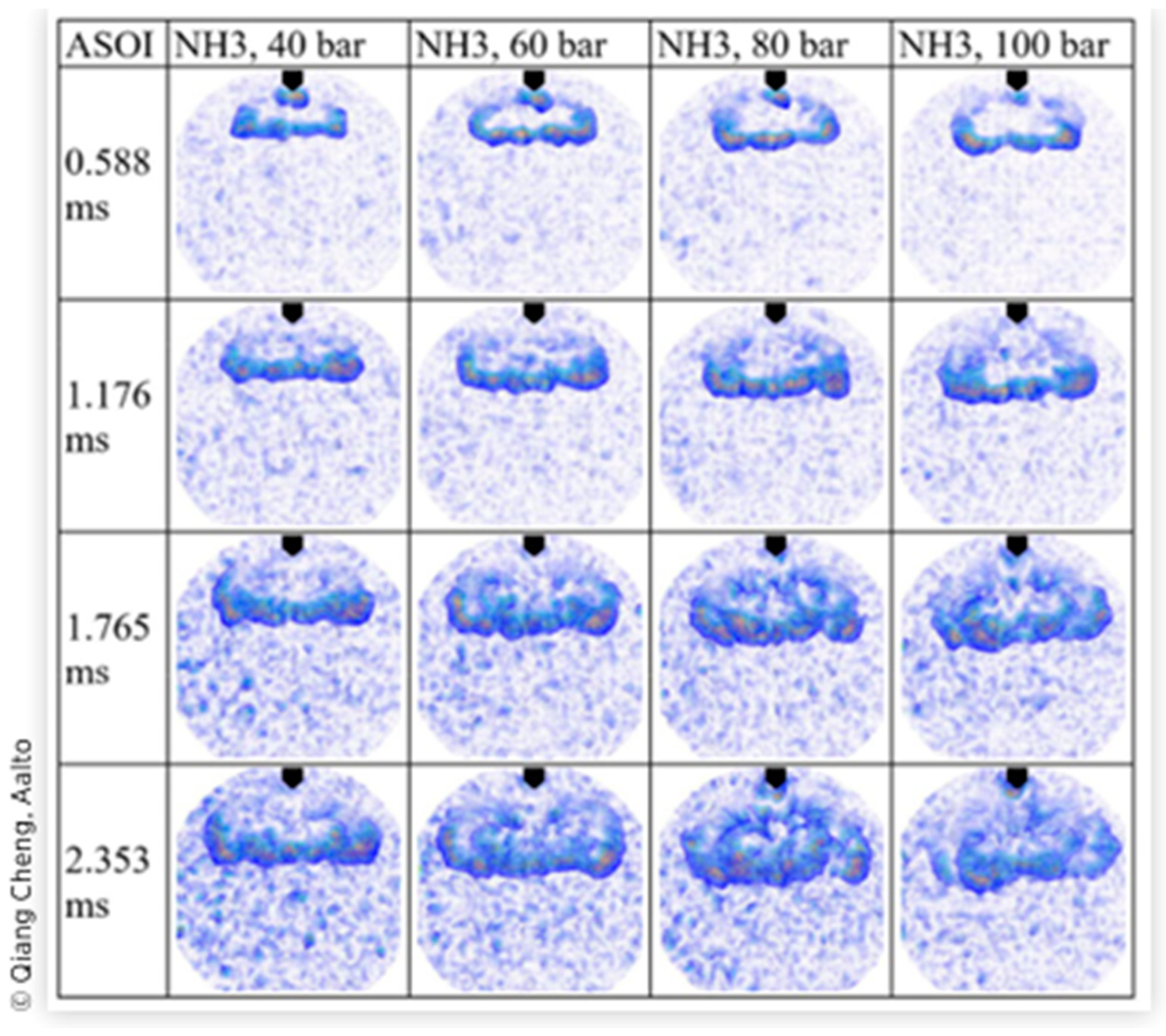
2.2. Direct Liquid Ammonia Injection Spray Characteristics and Effect on Combustion Performance

Direct liquid ammonia injection is gaining traction due to its cost-effectiveness and operational advantages over gaseous injection. Nonetheless, the unique characteristics of high-pressure liquid ammonia injection, especially flash boiling and large latent heat in a spray, are unavoidable due to ammonia’s low boiling point of 240.7 K (−33.5 °C), which causes rapid vaporization during injection and difficulties for ignition and combustion. This process is accompanied by adiabatic and evaporation cooling effects, which cool down the boiling droplet. In addition, a low flame speed relative to standard hydrocarbons remains a significant challenge for sustaining combustion stability. The combustion characteristics highlighted above are vital for designing and optimizing direct-combustion ammonia engines. Ongoing research delves into fundamental aspects like spray patterns [65], spray-combustion [66], and CI/SI engine flame characteristics [67] in this emerging field. In the earliest study of ammonia spray patterns [68], high-pressure ammonia spray (100 bar) characteristics were meticulously investigated under diverse chamber temperature and pressure conditions (at 25 °C with chamber pressures of 1 bar, 5 bar, 10 bar, and 20 bar, and at 50 °C with chamber pressures of 2 bar, 10 bar, 20 bar, and 40 bar), revealing vital insights for its application in internal combustion engines [68]. The researchers used high-speed imaging and sophisticated analysis techniques (Mie-Scattering and Schlieren Method) to investigate ammonia spray behaviours. The findings illustrate that ammonia’s penetration length diminishes as chamber pressure and temperature increase, with specific values observed at 25 °C and 50 °C under varied pressures. Notably, when chamber pressure surpasses ammonia’s vapor pressure (25 °C with 10 bar and 50 °C with 20 bar), the liquid spray shape mirrors the gas spray configuration, with lower Pc/Pv ratios enhancing vaporization. A significant flash-boiling phenomenon at a Pc/Pv of 0.1 was observed, merging spray plumes into a single jet, more pronounced at higher fuel temperatures. Comparatively, ammonia exhibited wider cone angles and faster evaporation rates than methane and iso-octane, with methane remaining gaseous and iso-octane showing no flash-boiling due to lower vapor pressure [68]. This comprehensive analysis underscores ammonia’s potential as a sustainable fuel, highlighting its enhanced vaporization and atomization capabilities. Despite these properties’ ignition and combustion challenges, the study provides a foundational understanding crucial for developing efficient combustion systems for marine and heavy-duty applications, marking significant strides in ammonia combustion research.
In the same context [69], Okafor et al. comprehensively studied the flame stability and emission characteristics of liquid ammonia spray co-fired with methane using a swirl combustor with preheated air at 500 K and liquid ammonia injected at (1.0 MPa at 295 K). Firstly, the study on non-reacting flow field measurements at the combustor’s liner exit revealed distinct velocity patterns (upwards near the liner wall and strong reverse flow in the central region) when variating swirled means inlet velocities (8 m/s and 24 m/s) [69]. Higher inlet velocity increases reserve flow speed and creates a significant inner recirculation zone, which improves the dispersion and vaporization of ammonia droplets and shortens the spray height. Secondly, the study investigated liquid ammonia stability since it poses a challenge compared to gas due to its unique properties. Pressure drop in the ammonia line can lead to vaporization and cavitation at the nozzle, causing unstable spray combustion. Therefore, the supply line was cooled to 279 K to maintain compressed ammonia in its liquid phase before injection and prevent unstable spray formation due to upstream vapor pockets of the nozzle causing fluctuation. The study showed the importance of preheated air further downstream, which influences flame stability and emission, as liquid ammonia exhibits a notable cooling effect due to its large evaporation latent heat and flash-boiling. The effective cooling effect and flash boiling favour stability; hence, the study reveals the successful stabilization of the liquid ammonia spray flame with the aid of swirled preheated air [69].
Another study investigated ammonia spray characteristics under various ambient pressure and temperature (air densities) conditions with a current GDI engine injector [70]. Ammonia was injected at 120 bar and 20 °C with an injection duration of 3.9 ms in a constant-volume 2.5 L chamber with a 30 bar and 200 °C pressured capacity. The Schlieren technique was used to capture and follow the liquid and vapor development of the spray. The experiment was conducted with various fuels (ethanol and gasoline), and a comparison was made. The findings showed differences in spray geometry and revealed how low air densities can impact ammonia spray penetration, causing it to exhibit longer morphology than ethanol and gasoline, resulting in jet collapse due to flash boiling. See Figure 6 comparing the spray shape of different fuels.
As ammonia exhibits a flash boiling effect due to its high vapor pressure, the likelihood of its occurrence is significant when ammonia is injected into a low-pressure environment (ambient temperature 20 °C) (see Figure 6), causing rapid evaporation due to the drop in pressure, releasing vapor bubbles within the spray, and then expanding quickly and cooling liquid ammonia surrounding it as a result of the high latent heat of vaporization. This cooling effect extracts heat, causing the vapor to condense back into liquid, creating a local low-pressure zone inside the spray, causing the overall spray structure to become unstable and collapse, as shown in Figure 6. However, these differences were less pronounced at higher air densities [70]. The finding also showed how ammonia spray penetration reached the chamber wall faster after 1.5 ms at 120 °C compared to ethanol (3.5 ms) and gasoline (3 ms), highlighting the high sensitivity of ammonia spray penetration to air density and temperature [70]. Overall, flash boiling introduces a dynamic process to enhance atomization and improve fuel mixing; hence, combustion efficiency with finer liquid droplets evaporating quickly is essential for complete combustion and NOx emission reduction as adequate mixing reduces the peak temperature in the combustor, lowering the formation of NOx. However, the jet collapse can potentially lead to combustion instability and inconsistencies in the fuel–air mixture if the mixture is not controlled with precision and accuracy.
Complementing previous papers [69], a subsequent study delved into liquid ammonia spray characteristics [71], particularly regarding flash boiling and atomization using a pressure swirl atomizer equipped with Delavan Type WDA nozzles, highlighting the impact of ammonia’s unique properties (viscosity, surface tension, and density) and comparing them with ethanol spray through shadowgraph imaging. The experiment used an atomizer to produce a swirling flow via a tangential slot spread out in a hollow cone shape formed by centrifugal force and a vacuum zone in the centre for adequate fuel–air mixing at various nozzles (No. five: orifice diameter of 0.64 mm, water flow rate of 14.5 L/h at 0.5 MPa, and No. eighteen: orifice diameter of 1.32 mm, water flow rate of 51.8 L/h at 0.5 MPa) and spray cone angle (30° and 80°) specifications [71]. A rectified air flow was fed to the chamber to carry the spray downstream with one-tenth liquid velocity controlled for reverse flow prevention. The upstream supply line tubes were cooled with dry ice to prevent ammonia from evaporating prematurely before reaching the nozzle, as ammonia exhibits a unique evaporating spray due to its low boiling point. The study emphasizes [69] the necessity of maintaining a stable spray and revealed that ammonia decompression evaporation occurs due to pressure drop when ammonia is supplied without cooling, leading to flow rate and spray cone fluctuation. One notable observation highlighted [70], is the absence of visible droplets downstream due to the formation of tiny droplets resulting from high degrees of superheat during rapid depressurization (flash boiling), which can lead to spray collapse [70]. However, the ammonia flow rate and spray cones were stable when the supply line cooled, although downstream droplets evaporated after some time. The finding revealed that at a 30° nozzle, ammonia spray showed smaller droplets and a significantly larger spray cone angle compared to ethanol, attributed to ammonia’s low viscosity, which enhances atomization; nevertheless, at an 80° nozzle, there are no significant differences shown on the ammonia, ethanol, and water spray cone angle, demonstrating how under the overpowering effect of centrifugal force, the viscosity and surface tension impact is reduced [71]. The findings showed a larger droplet formation using the No. eighteen atomizer than in No. five initially but a darker and blurry spray cone after a few seconds due to heat exchange with ambient gas [71]. Overall, the study emphasizes the distinct behaviour of ammonia critical for optimizing fuel–air mixture and combustion efficiency. Larger spray cone angles ensure better fuel–air mixture and atomization, mainly with the 30° atomizer, help with NOx emissions reduction, promoting complete combustion, and optimizing ammonia injection is essential for an injection design system that leverages ammonia properties, thereby enhancing engine performance.
Similarly [72], a further investigationtitled ‘Dynamics of the Ammonia Spray Using High-Speed Schlieren Imaging’ explored ammonia spray characteristics using high-pressure GDI injection systems with a hollow cone piezoelectric injector. The study investigated spray characteristics at various pressure injections (40, 60, 80, and 100 bar), pressure chambers (5, 10, and 20 bar), and lift needles (35, 50, and 65 μm).Ammonia spray behaviour was compared with renewable fuels like ethanol and methanol under engine-like conditions in a constant volume chamber using a high-speed schlieren technique and novel optical flow method to capture and analyse the dynamics of the spray. The results reveal that, due to ammonia’s unique properties like density and viscosity, it exhibited longer spray penetration and larger cone angles. The technique of optical flow was used to capture the velocity field and to give a detailed visualization of turbulence and flow patterns within the spray chamber. The results highlighted the vortices’ role in promoting fuel–air mixture by creating local turbulence and helping the fuel spray to break up and disperse evenly and efficiently to improve ignition, combustion, and emission reduction, as represented in Figure 7.
The investigation also studied the effect of pressure injection on the ammonia spray characteristics [72]. It revealed how higher injection pressure induced greater turbulence and promoted atomization (finer droplets), penetration, and spray area due to increased momentum. However, shorter penetration and smaller spray areas were observed as the result of the pressure chamber due to greater air drag force, which increases droplet coalescence and reduces secondary spray breakup, affecting fuel distribution. The effect of the pressure ratios of four (40/10 and 80/20) and eight (40/5 and 80/10) on the spray characteristics and needle lift was studied [72]. The findings reveal sharper spray edges, longer penetration, and larger spray areas, highlighting the unique spray behaviour of ammonia determined by the combined effect of chamber and injection pressures. The ammonia phase transition from liquid to vapor showed nonlinear characteristics at a similar pressure ratio. The study also showed a higher injection rate and momentum with needle lift increase, resulting in a larger spray area and longer penetration. This study emphasizes the previous papers [70,71] on ammonia compared to methanol and ethanol, which exhibit a larger area and penetration spray due to their lower viscosity and density and faster evaporation rate due to their higher vapor pressure. Overall, advanced injection design systems are critical, and optimizing injection parameters is vital for enhancing engine performance and emission reduction.
Previous studies on flash boiling have suggested many transition criteria for the different flash-boiling regimes, based on pressure ratio and factors such as spray angle, Jacob number, vapor-to-liquid density ratio (ϕ) [70,72], Weber number (Wev), external bubble nucleation, and the effect of aspect ratio. To expand on these understandings of the factors that influence flash boiling [73,74], an investigation was conducted to examine the effect of nozzle geometry and injection temperature on the flash transition of liquid ammonia spray, using a high-pressure GDI injection with a single nozzle hole to study liquid ammonia spray behaviour under different injection temperatures (from 270 K to 290 K) and nozzle geometries with a range of injection pressures (from 1.2 MPa to saturated pressure) [74]. The aspect ratio (L/D: 2.5, 5, and 10) and the degree of superheat (Rp = 3.5, 5.1, 5.2, 5.3, 8, 8.5, 9) were used as the nozzle geometries and injection temperatures, respectively, to explore the liquid ammonia spray flash transition, where D (between 0.1 mm and 0.21 mm) is the diameter of the orifice and L is the length. The findings revealed the formation of a straight ammonia jet for a low aspect ratio (2.5 to 5), indicating mechanical breakup and bubble appearance under higher superheat at L/D = 5, implying the flash boiling onset [74]. As the L/D increases to 10, a bowl-like spray pattern emerges composed of an inner liquid jet surrounded by fine droplets, a typical characteristic of flash-boiling atomization, which agrees with previous studies on flash-boiling [71,73]. Analysing the degree of superheat, the results showed a notable change in the spray pattern but minimal variation at L/D = 2.5. However, a small temperature variation (20 k) significantly alters the spray pattern for L/D = 5 and 10, indicating that at L/D = 5, the spray transitioned from purely mechanical breakup to partial flash (liquid core surrounded by fine droplets) and at L/D = 10, it transitioned from partial flash to full flash (a lack of liquid core visibility) [73,74]. On the other hand, the spray angle evolution exhibited high variation when L/D and superheat increased, jumping from 40° at L/D = 5 to 120° at L/D = 10. Higher L/D and superheat, therefore, speed up the transition to flashing, forming fine droplets that ensure effective fuel–air distribution and atomization and boost complete combustion. The experiment also highlighted the effect of nozzle spray geometry on the inner flow and spray characteristic using a glass nozzle and how a slight change in orifice can significantly impact the flashing behaviour and flow rate as represented in Figure 8, where the red square represents the enlarged image region (microscope lens), and the dashed white region illustrates the mixed liquid–gas region [74].
Internal flashing contributes to finer atomization and uniform spray distribution but a lower flow rate. These studies offer a solid foundation on the practical consideration criteria when designing an efficient liquid ammonia injection system, taking into consideration its properties (viscosity and density), injection conditions, and nozzle geometries, and offer a clear understanding of the flash boiling phenomenon to improve combustion, reduce emissions, and enhance engine performance. To improve efficient liquid ammonia spray combustion, further investigation of the geometric variation, like the effect of orifice section change, needs to be conducted quantitatively for further flash condition optimization. Flash transition criteria need to be explored further, considering the impact of heterogeneous nucleation and the reattachment of liquid to the orifice wall when associated with a larger L/D.

3. Ammonia Combustion in Gas Turbines

Ammonia as a gas turbine fuel has garnered attention since the 1960s, experiencing renewed interest in Japan and Europe since 2017–2018. Japan’s Ministry for Economic, Trade, and Industry devised a strategy for ammonia fuel, targeting carbon neutrality in industries by 2050. In 2023, IHI and General Electric initiated a collaboration on multi-hundred-megawatt ammonia-exclusive gas turbines [75]. In the EU, SINTEF’s project, ‘Enabling safe, clean, and efficient utilization of hydrogen and ammonia as carbon-free fuels,’ started in 2017, and its successor in 2023, ‘DECAMMP -Decomposed ammonia for carbon-free power generation,’ [76] is investigating the partial decomposition of ammonia to create a blend suitable for GTs.
The initial successful GT using ammonia produced 44.4 kW at 80,000 rpm [77]. Despite its relatively high combustion efficiency, issues such as significant unburnt ammonia and NOx emissions indicate the poor homogeneity of the fuel–air mixture, leading to the coexistence of fuel-rich and fuel-lean zones in combustion. Addressing NOx emissions and optimising fuel utilisation are two crucial challenges for ammonia GTs. Early attempts to optimise combustor designs, such as swirl burners [78], focused on adjusting the swirl number, a geometric parameter determined by the inner and outer diameters of a swirler and swirler vane angle. The swirl number rose from 0.736 to 1.27, enhancing turbulent fuel–air mixing and prolonging fuel residence time in combustion. However, this increase in swirl number resulted in a narrower flame stability region with respect to the equivalent ratio. A comprehensive combustor design introduced a two-stage burner [79], with rich combustion in the primary stage and lean burn in the secondary stage (see Figure 9). The study examined the impacts of dilution holes, air swirler area, sleeve-fitting gap area, and cooling holes. Compared to the baseline system, NO was reduced by two-thirds to 337 ppm (@ 16% O2), along with observed reductions in unburnt NH3 and N2O emissions.
In contrast to non-premixed combustion with separate fuel and air supplies, a first preliminary study explored a premixed combustion of a 50:50 vol% mixture of ammonia and hydrogen at an equivalent ratio (ER) ranging from 0.43 to 0.52 [80]. At Φ = 0.43, NOx emissions were in the low hundreds of ppm, but hydrogen flashbacks occurred due to its high diffusivity. This approach, known as lean burn dry low emissions (DLE), reduced flame temperature, and diminished thermal NO formation. In another study [81], a two-stage DLE burner achieved low NOx emissions (below 80 ppm @ 16% O2) with an overall ER as low as 0.38, considering both primary and secondary combustion. This outperformed non-premixed combustion across a range of overall ER (0.38 to 0.8) and its superior NOx emissions were enhanced at elevated pressure (0.2–0.3 MPa).
Moderate or intense low-oxygen dilution (MILD) is an alternative approach to reduce thermal NOx formation, relying on local distributed auto-ignition instead of a flame propagation mechanism. A 5 kW cyclonic flow burner [82] in a MILD combustion study exhibited extremely low NOx levels around 10 ppm @ 16% O2, but with unburnt NH3 reaching 1000 ppm at an overall ER of 1.1 and an air preheated temperature of 900 K. Quantifying exhaust gas recirculation (EGR) was challenging due to the cyclonic flow burner design. In a theoretical study [83], at a pressure ratio of 20, an EGR ratio of 0.6, and an ER between 1 and 1.1, the GT was predicted as having NO emission in the single-digit ppm range due to a lower gas turbine temperature of 1800 K.
The third approach, humification, was presented in a study using a mixture of 70% NH3 and 30% H2 [84], incorporated steam injection with a maximum steam/fuel mass ratio of 0.4, thereby, increasing power output and decreasing thermal NOx. Results indicated NOx emissions just above 10 ppm at an inlet temperature of 400 K and ER of 1.2. In a subsequent numerical work [84], humification was integrated into a two-stage burner known as rich-burn, quick-quench, and lean-burn (RQL). RQL demonstrated high performance, consuming most reactive species, with NOx production after the lean burn zone calculated as 127 ppm (@ 15% O2). A numerical comparison of three combustion concepts (DLE, MILD, and RQL) for ammonia GTs [85] revealed that RQL and MILD achieved the lowest emissions, while the DLE concept exhibited acceptable values only under conditions considered unstable, where laminar flame speeds were below 3 cm/s.
Since ammonia is primarily stored in its liquid phase, liquid ammonia’s direct combustion is the focus of renewed research for gas turbines, aiming to minimise fuel preparation and start-up. In a preliminary study [69], a single-stage swirl combustor used separate liquid ammonia (1.0 MPa at 295 K), methane, and air additions. With 70% ammonia in the fuel (by heat fraction) and an elevated 500 K inlet air temperature, stable flames occurred within a narrower ER range of 0.66 to 1.37. Optimal results showed NO and unburnt NH3 emissions near 1000 ppm and 100 ppm, respectively, at ER 1.06. The presence of methane led to a swift increase in toxic hydrogen cyanide (HCN) from 50 ppm at an ER of 1.06 to 200 ppm at an ER of 1.1. A study on a downsized industrial GT burner and local ammonia decomposition found that NOx emissions are optimal (see Figure 10) when the overall ER is between 1.2 and 1.4 and the decomposition rate of ammonia (DCR) is low, indicating a high ammonia concentration in the blend [86].
Another study numerically investigates liquid ammonia spray combustion in a gas turbine combustor at a lower pressure of 0.1 MPa, co-firing with gas hydrogen while maintaining a 50% ammonia energy fraction compared to gas ammonia [87]. The results showed that a preheated tangential swirling flow allowed stable liquid NH3 spray flames across equivalence ratios of 0.99 to 1.49 despite NH3 vapor at –60 °C. The optimal equivalence ratio for minimizing NO and unburnt NH3 emissions was approximately 1.35 [87]. In a later study [88], Okafor et al. explored flame stability and emission control challenges of liquid ammonia spray combustion using a two-stage gas microturbine at 0.25 MPa and an input power of up to 230 kW [88]. Findings revealed that injecting liquid ammonia spray into a methane–air flame yielded rapid combustor cooling and flame blowoff. Nonetheless, the stable combustion of pure liquid ammonia was achieved without slot film cooling. The results proved that two-stage rich-lean combustion decreased emissions, though the primary combustion zone required better flame stability. Additionally, improving the combustor inlet temperature and minimizing wall heat loss enhanced combustion, and decreased emissions of NO, NO2, N2O, NH3, HCN, and CO when ammonia was co-fired with methane. Pure ammonia combustion led to higher emissions due to droplet distribution challenges and heat transfer, requiring further optimization. In a subsequent numerical study [89], liquid ammonia spray characteristics and co-combustion with hydrogen were explored at 50–70% of ammonia (by heat fraction). The validated ammonia droplet size was 15–20 µm at 0.3 MPa injection pressure. The flash boiling of liquid ammonia caused a low temperature (270–280 K) near the nozzle tip, indicating the need for high enthalpy air intake and extensive combustor recirculation for flame stability [89].
In most combustor studies, additional fuels like hydrogen or methane were employed to enhance ammonia flame speed and stability, which were also used to initiate stable combustion before injecting ammonia, underscoring the challenge of ammonia ignition. Numerous studies delved into the combustion, mechanisms, and emissions of ammonia blends, e.g., 61% mol NH3–39% mol CH4 [90], 30%NH3–70%CH3 by heat fraction [91], NH3-HHO in ratios of 10:3 to 10:7 [92], and 28.8–41.4% NH3– 71.2–58.6% CH4 by heat fraction [93]. As the ammonia fraction increased, combustion efficiency decreased, and global warming potential rose due to higher N2O emissions [92].

4. Conclusions

Studies and investigations have been conducted worldwide, putting valuable efforts into tackling CO2 emissions to respond to the growing challenges of climate change. This paper highlighted the latest advancements in the combustion of neat or high-percentage ammonia as a carbon-free fuel. Despite ammonia’s historical use as a fuel and recent research on ammonia combustion, achieving an optimal balance between combustion efficiency and minimal NOx emissions remains a challenge for ICEs and GTs, impeding the swift deployment of new power generation and propulsion models.
  • Ammonia’s uniqueness highlights its potential in the transition to net zero, owing to its carbon-free combustion, high energy density, and undeniable potential for gas turbine and internal combustion engines. However, it is crucial to recognize ammonia’s inherent challenges and complexity, raising a safety concern and the issue related to public acceptance as a fuel. Therefore, these challenges need to be addressed rigorously.
  • For spark ignition engines, achieving ammonia combustion efficiency and reliable ignition will not only demand advanced technologies such as turbulent jet ignition and partially cracked ammonia but also an increased comprehension of the combustion kinetics of ammonia. The gap between laboratory investigations and real-world deployment must be bridged and will require fundamental research coupled with practical application.
  • Compression ignition engines offer the potential for ammonia utilization in maritime transportation sectors. Implementing multi-fuel injection strategies and secondary promoter fuels provide ways to control emissions and improve performance. However, with these integrated solutions it is essential to balance the cost and complexity of the system to guarantee its feasibility.
  • Gas turbines provide a remarkable, exciting frontier for the combustion of ammonia, innovative combustor design, and ammonia–hydrogen or methane blending that can play a key role in achieving decarbonization; nonetheless, critical challenges like NOx emissions still need to be addressed and demand the precise control of the combustion conditions and a robust after-treatment system.
  • Outlook: Ammonia’s journey to becoming a mainstream solution will become a reality only by addressing its limitations thoroughly, which implies developing advancing emission control technologies, scalable safety solutions, and combustion performance efficiency in collaboration with academics, industry, and policymakers.
  • Ammonia is far from perfect, like a broad range of fuels; however, its role in achieving net zero emissions is vital. Therefore, a pragmatic approach is necessary to leverage its strengths while addressing its weaknesses, and prioritizing innovation can push ammonia forward in becoming a cornerstone of energy systems in the future.

Author Contributions

Conceptualization, E.F.E., E.N. and D.W; methodology, E.F.E., E.N. and D.W; formal analysis, E.F.E., E.N. and D.W.; investigation, E.F.E., E.N. and D.W.; writing—original draft preparation, E.F.E., E.N. and D.W.; writing—review and editing, E.F.E., E.N. and D.W.; supervision, D.W.; project administration, D.W.; funding acquisition, D.W. All authors have read and agreed to the published version of the manuscript.

Funding

This research was funded by Engineering and Physical Sciences Research Council (EPSRC), grants number EP/W016656/1 and EP/Y024605/1.

Conflicts of Interest

The authors declare no conflicts of interest.

Nomenclature

ICEsInternal combustion engines
CICompression ignition engines
SISpark ignition engines
NH3Ammonia
LNH3Liquid ammonia
H2Hydrogen
CH4Methane
NOxNitrogen oxides
N2ONitrous oxide
CO2Carbon dioxide
GTsGas turbines
BSECBrake-specific energy consumption
BTDCBefore top dead centre
HCHydrocarbon
COCarbon monoxide
IMEPIndicated mean effective pressure
COVCoefficient of variation
CRCompression ratio
λAir ratio
GWPGlobal warming potential
ΔH°Standard enthalpy change
RuRuthenium
Ni–PtNickel–platinum
AECAmmonia electrolyte cell
TJIPrechamber turbulent jet ignition
PACPlasma-assisted combustion
OOxygen
OHHydroxyl radical
HNO Nitroxyl radical
SCRSelective catalytic reduction
RCCIReactivity-controlled compression ignition
ITEIndicated thermal efficiency
GHGGreenhouse gas
PMParticulate matter
HVOHydrotreated vegetable oil
CENCombustion enhancer containing alkyl nitrates
CACrank angle
ATDCAfter top dead centre
TDCTop dead centre
Pc/Pv Pressure chamber/ Pressure vapour ratio
ϕVapor-to-liquid density ratio
GDIGasoline direct injection
L/DAspect ratio (length-to-diameter orifice)
RpDegree of superheat
EREquivalent ratio
DLEDry low emissions
MILDModerate or intense low-oxygen dilution
EGRExhaust gas recirculation
RQLRich-burn, quick-quench, lean-burn
DCRDuty cycle ratio
HCNHydrogen cyanide
DCRDecomposition rate of ammonia

References

  1. UNFCCC. Adoption of the Paris Agreement—Paris Agreement Text English; UNFCCC: Bonn, Germany, 2015. [Google Scholar]
  2. Do Sacramento, E.; Carvalho, P.C.; De Lima, L.; Veziroglu, T. Feasibility study for the transition towards a hydrogen economy: A case study in Brazil. Energy Policy 2013, 62, 3–9. [Google Scholar] [CrossRef]
  3. Giddey, S.; Badwal, S.; Kulkarni, A. Review of electrochemical ammonia production technologies and materials. Int. J. Hydrogen Energy 2013, 38, 14576–14594. [Google Scholar] [CrossRef]
  4. Yapicioglu, A.; Dincer, I. A review on clean ammonia as a potential fuel for power generators. Renew. Sustain. Energy Rev. 2019, 103, 96–108. [Google Scholar] [CrossRef]
  5. Dimitriou, P.; Javaid, R. A review of ammonia as a compression ignition engine fuel. Int. J. Hydrogen Energy 2020, 45, 7098–7118. [Google Scholar] [CrossRef]
  6. Mozafari-Varnusfadrani, A. Predictions and Measurements of Spark-Ignition Engine Characteristics Using Ammonia and Other Fuels; Queen Mary University of London: London, UK, 1988. [Google Scholar]
  7. Duynslaegher, C.; Jeanmart, H.; Vandooren, J. Ammonia combustion at elevated pressure and temperature conditions. Fuel 2010, 89, 3540–3545. [Google Scholar] [CrossRef]
  8. Vukadinovic, V.; Habisreuther, P.; Zarzalis, N. Experimental study on combustion characteristics of conventional and alternative liquid fuels. J. Eng. Gas Turbines Power 2012, 134, 121504. [Google Scholar] [CrossRef]
  9. Grannell, S.M.; Assanis, D.N.; Bohac, S.V.; Gillespie, D.E. The fuel mix limits and efficiency of a stoichiometric, ammonia, and gasoline dual fueled spark ignition engine. J. Eng. Gas Turbines Power. 2008, 130, 042802. [Google Scholar] [CrossRef]
  10. Bicer, Y.; Dincer, I.; Vezina, G.; Raso, F. Impact assessment and environmental evaluation of various ammonia production processes. Environ. Manag. 2017, 59, 842–855. [Google Scholar] [CrossRef]
  11. Zhou, W.; Zhu, B.; Li, Q.; Ma, T.; Hu, S.; Griffy-Brown, C. CO2 emissions and mitigation potential in China’s ammonia industry. Energy Policy 2010, 38, 3701–3709. [Google Scholar] [CrossRef]
  12. Andres, R.J.; Boden, T.A.; Bréon, F.-M.; Ciais, P.; Davis, S.; Erickson, D.; Gregg, J.S.; Jacobson, A.; Marland, G.; Miller, J. A synthesis of carbon dioxide emissions from fossil-fuel combustion. Biogeosciences 2012, 9, 1845–1871. [Google Scholar] [CrossRef]
  13. Andres, R.J.; Gregg, J.S.; Losey, L.; Marland, G.; Boden, T.A. Monthly, global emissions of carbon dioxide from fossil fuel consumption. Tellus B Chem. Phys. Meteorol. 2011, 63, 309–327. [Google Scholar] [CrossRef]
  14. Zamfirescu, C.; Dincer, I. Ammonia as a green fuel and hydrogen source for vehicular applications. Fuel Process. Technol. 2009, 90, 729–737. [Google Scholar] [CrossRef]
  15. Mørch, C.S.; Bjerre, A.; Gøttrup, M.P.; Sorenson, S.C.; Schramm, J. Ammonia/hydrogen mixtures in an SI-engine: Engine performance and analysis of a proposed fuel system. Fuel 2011, 90, 854–864. [Google Scholar] [CrossRef]
  16. Duynslaegher, C.; Contino, F.; Vandooren, J.; Jeanmart, H. Modeling of ammonia combustion at low pressure. Combust. Flame 2012, 159, 2799–2805. [Google Scholar] [CrossRef]
  17. Sahoo, B.; Sahoo, N.; Saha, U. Effect of engine parameters and type of gaseous fuel on the performance of dual-fuel gas diesel engines—A critical review. Renew. Sustain. Energy Rev. 2009, 13, 1151–1184. [Google Scholar] [CrossRef]
  18. Zhou, L.; Zhong, L.; Liu, Z.; Wei, H. Toward highly-efficient combustion of ammonia–hydrogen engine: Prechamber turbulent jet ignition. Fuel 2023, 352, 129009. [Google Scholar] [CrossRef]
  19. Cai, T.; Zhao, D.; Gutmark, E. Overview of fundamental kinetic mechanisms and emission mitigation in ammonia combustion. Chem. Eng. J. 2023, 458, 141391. [Google Scholar] [CrossRef]
  20. Riviera. WinGD on Track to Deliver Ammonia Engines in 2025. Available online: https://www.rivieramm.com/news-content-hub/news-content-hub/wingd-on-track-to-deliver-ammonia-engines-in-2025-76985 (accessed on 10 October 2024).
  21. Lindstrand, N. MAN Energy Solutions Is Developing a Fuel-Flexible, Two-Stroke Ammonia Engine as a Key Technology in the Maritime Energy Transition. MAN. 2023. Available online: https://www.man-es.com/discover/two-stroke-ammonia-engine (accessed on 15 October 2024).
  22. Alder, I. Wärtsilä Continues to Set the Pace for Marine Decarbonisation with Launch of World-First 4-Stroke Engine-Based Ammonia Solution. Wärtsilä Corporation. 2023. Available online: https://www.wartsila.com/media/news/15-11-2023-wartsila-continues-to-set-the-pace-for-marine-decarbonisation-with-launch-of-world-first-4-stroke-engine-based-ammonia-solution-3357985 (accessed on 17 October 2024).
  23. Line, N. Maritime Consortium Successfully Completes Ammonia Co-Firing Test Using Cutting-Edge Ammonia-Fueled Engine. 2023. Available online: https://www.nyk.com/english/news/2023/20230516_01.html (accessed on 20 October 2024).
  24. Rimmele, C. MAHLE Powertrain Drives the Development of Ammonia Combustion for Heavy Duty Engines. 2023. Available online: https://www.mahle-powertrain.com/en/news-and-press/press-releases/mahle-powertrain-drives-the-development-of-ammonia-combustion-for-heavy-duty-engines-91713#:~:text=MAHLE%20Powertrain%20drives%20the%20development%20of%20ammonia%20combustion%20for%20heavy%20duty%20engines (accessed on 25 October 2024).
  25. Hydrofuel. Engine Conversions. 2023. Available online: https://www.mahle-powertrain.com/en/news-and-press/press-releases/mahle-powertrain-drives-the-development-of-ammonia-combustion-for-heavy-duty-engines-91713 (accessed on 26 October 2024).
  26. Kable, G. GAC and Toyota Develop Ammonia Engine for 90% CO2 Reduction. Four-Cylinder Engine Is the First Ammonia-Fuelled Engine for Passenger Cars; Could Be a Hydrogen Alternative. 2023. Available online: https://www.autocar.co.uk/car-news/new-cars/gac-and-toyota-develop-ammonia-engine-90-co2-reduction (accessed on 30 October 2024).
  27. Ma, F.; Guo, L.; Li, Z.; Zeng, X.; Zheng, Z.; Li, W.; Zhao, F.; Yu, W. A review of current advances in ammonia combustion from the fundamentals to applications in internal combustion engines. Energies 2023, 16, 6304. [Google Scholar] [CrossRef]
  28. Tornatore, C.; Marchitto, L.; Sabia, P.; De Joannon, M. Ammonia as green fuel in internal combustion engines: State-of-the-art and future perspectives. Front. Mech. Eng. 2022, 8, 944201. [Google Scholar] [CrossRef]
  29. Jespersen, M.C.; Rasmussen, T.Ø.H.; Ivarsson, A. Widening the operation limits of a SI engine running on neat ammonia. Fuel 2024, 358, 130159. [Google Scholar] [CrossRef]
  30. Ryu, K.; Zacharakis-Jutz, G.E.; Kong, S.-C. Effects of gaseous ammonia direct injection on performance characteristics of a spark-ignition engine. Appl. Energy 2014, 116, 206–215. [Google Scholar] [CrossRef]
  31. Grannell, S.M.; Assanis, D.N.; Gillespie, D.E.; Bohac, S.V. Exhaust emissions from a stoichiometric, ammonia and gasoline dual fueled spark ignition engine. In Proceedings of the Internal Combustion Engine Division Spring Technical Conference, Milwaukee, WI, USA, 3–6 May 2009; pp. 135–141. [Google Scholar]
  32. Kurien, C.; Varma, P.S.; Mittal, M. Effect of ammonia energy fractions on combustion stability and engine characteristics of gaseous (ammonia/methane) fuelled spark ignition engine. Int. J. Hydrogen Energy 2023, 48, 1391–1400. [Google Scholar] [CrossRef]
  33. Mounaïm-Rousselle, C.; Bréquigny, P.; Dumand, C.; Houillé, S. Operating limits for ammonia fuel spark-ignition engine. Energies 2021, 14, 4141. [Google Scholar] [CrossRef]
  34. Lhuillier, C.; Brequigny, P.; Contino, F.; Mounaïm-Rousselle, C. Experimental study on ammonia/hydrogen/air combustion in spark ignition engine conditions. Fuel 2020, 269, 117448. [Google Scholar] [CrossRef]
  35. Mounaïm-Rousselle, C.; Brequigny, P. Ammonia as fuel for low-carbon spark-ignition engines of tomorrow’s passenger cars. Front. Mech. Eng. 2020, 6, 70. [Google Scholar] [CrossRef]
  36. Qi, Y.; Liu, W.; Liu, S.; Wang, W.; Peng, Y.; Wang, Z. A review on ammonia-hydrogen fueled internal combustion engines. ETransportation 2023, 18, 100288. [Google Scholar] [CrossRef]
  37. Pyrc, M.; Gruca, M.; Tutak, W.; Jamrozik, A. Assessment of the co-combustion process of ammonia with hydrogen in a research VCR piston engine. Int. J. Hydrogen Energy 2023, 48, 2821–2834. [Google Scholar] [CrossRef]
  38. Westlye, F.R.; Ivarsson, A.; Schramm, J. Experimental investigation of nitrogen based emissions from an ammonia fueled SI-engine. Fuel 2013, 111, 239–247. [Google Scholar] [CrossRef]
  39. Dinesh, M.; Pandey, J.K.; Kumar, G. Study of performance, combustion, and NOx emission behavior of an SI engine fuelled with ammonia/hydrogen blends at various compression ratio. Int. J. Hydrogen Energy 2022, 47, 25391–25403. [Google Scholar] [CrossRef]
  40. Ryu, K.; Zacharakis-Jutz, G.E.; Kong, S.-C. Performance enhancement of ammonia-fueled engine by using dissociation catalyst for hydrogen generation. Int. J. Hydrogen Energy 2014, 39, 2390–2398. [Google Scholar] [CrossRef]
  41. Ezzat, M.; Dincer, I. Development and assessment of a new hybrid vehicle with ammonia and hydrogen. Appl. Energy 2018, 219, 226–239. [Google Scholar] [CrossRef]
  42. Koike, M.; Suzuoki, T.; Takeuchi, T.; Homma, T.; Hariu, S.; Takeuchi, Y. Cold-start performance of an ammonia-fueled spark ignition engine with an on-board fuel reformer. Int. J. Hydrogen Energy 2021, 46, 25689–25698. [Google Scholar] [CrossRef]
  43. Kim, J.; Um, D.; Kwon, O. Hydrogen production from burning and reforming of ammonia in a microreforming system. Energy Convers. Manag. 2012, 56, 184–191. [Google Scholar] [CrossRef]
  44. Zhao, H.; Zhao, D.; Sun, D.; Semlitsch, B. Electrical power, energy efficiency, NO and CO emissions investigations of an ammonia/methane-fueled micro-thermal photovoltaic system with a reduced chemical reaction mechanism. Energy 2024, 305, 132248. [Google Scholar] [CrossRef]
  45. Meng, X.; Zhao, C.; Cui, Z.; Zhang, X.; Zhang, M.; Tian, J.; Long, W.; Bi, M. Understanding of combustion characteristics and NO generation process with pure ammonia in the pre-chamber jet-induced ignition system. Fuel 2023, 331, 125743. [Google Scholar] [CrossRef]
  46. Zhang, X.; Tian, J.; Cui, Z.; Xiong, S.; Yin, S.; Wang, Q.; Long, W. Visualization study on the effects of pre-chamber jet ignition and methane addition on the combustion characteristics of ammonia/air mixtures. Fuel 2023, 338, 127204. [Google Scholar] [CrossRef]
  47. Liu, Z.; Zhou, L.; Wei, H. Experimental investigation on the performance of pure ammonia engine based on reactivity controlled turbulent jet ignition. Fuel 2023, 335, 127116. [Google Scholar] [CrossRef]
  48. Uddeen, K.; Tang, Q.; Shi, H.; Magnotti, G.; Turner, J. A novel multiple spark ignition strategy to achieve pure ammonia combustion in an optical spark-ignition engine. Fuel 2023, 349, 128741. [Google Scholar] [CrossRef]
  49. Guo, B.; Ichiyanagi, M.; Kajiki, K.; Aratake, N.; Zheng, Q.; Kodaka, M.; Suzuki, T. Combustion analysis of ammonia fueled high compression ratio si engine with glow plug and sub-chamber-effects of ammonia content under condition of co-combustion with gasoline/ammonia/air. Int. J. Automot. Eng. 2022, 13, 1–8. [Google Scholar] [CrossRef] [PubMed]
  50. Engelmann, Y.; van’t Veer, K.; Gorbanev, Y.; Neyts, E.C.; Schneider, W.F.; Bogaerts, A. Plasma catalysis for ammonia synthesis: A microkinetic modeling study on the contributions of Eley–Rideal reactions. ACS Sustain. Chem. Eng. 2021, 9, 13151–13163. [Google Scholar] [CrossRef]
  51. Faingold, G.; Lefkowitz, J.K. A numerical investigation of NH3/O2/He ignition limits in a non-thermal plasma. Proc. Combust. Inst. 2021, 38, 6661–6669. [Google Scholar] [CrossRef]
  52. Chiong, M.-C.; Chong, C.T.; Ng, J.-H.; Mashruk, S.; Chong, W.W.F.; Samiran, N.A.; Mong, G.R.; Valera-Medina, A. Advancements of combustion technologies in the ammonia-fuelled engines. Energy Convers. Manag. 2021, 244, 114460. [Google Scholar] [CrossRef]
  53. Niki, Y.; Yoo, D.-H.; Hirata, K.; Sekiguchi, H. Effects of ammonia gas mixed into intake air on combustion and emissions characteristics in diesel engine. In Proceedings of the Internal Combustion Engine Division Fall Technical Conference, Greenville, SC, USA, 9–12 October 2016. [Google Scholar]
  54. Niki, Y.; Nitta, Y.; Sekiguchi, H.; Hirata, K. Emission and combustion characteristics of diesel engine fumigated with ammonia. In Proceedings of the Internal Combustion Engine Division Fall Technical Conference, San Diego, CA, USA, 4–7 November 2018. [Google Scholar]
  55. Jin, S.; Wu, B.; Zi, Z.; Yang, P.; Shi, T.; Zhang, J. Effects of fuel injection strategy and ammonia energy ratio on combustion and emissions of ammonia-diesel dual-fuel engine. Fuel 2023, 341, 127668. [Google Scholar] [CrossRef]
  56. Førby, N.; Thomsen, T.B.; Cordtz, R.F.; Bræstrup, F.; Schramm, J. Ignition and combustion study of premixed ammonia using GDI pilot injection in CI engine. Fuel 2023, 331, 125768. [Google Scholar] [CrossRef]
  57. Xu, L.; Xu, S.; Bai, X.-S.; Repo, J.A.; Hautala, S.; Hyvönen, J. Performance and emission characteristics of an ammonia/diesel dual-fuel marine engine. Renew. Sustain. Energy Rev. 2023, 185, 113631. [Google Scholar] [CrossRef]
  58. Pei, Y.; Wang, D.; Jin, S.; Gu, Y.; Wu, C.; Wu, B. A quantitative study on the combustion and emission characteristics of an Ammonia-Diesel Dual-fuel (ADDF) engine. Fuel Process. Technol. 2023, 250, 107906. [Google Scholar] [CrossRef]
  59. Mi, S.; Wu, H.; Pei, X.; Liu, C.; Zheng, L.; Zhao, W.; Qian, Y.; Lu, X. Potential of ammonia energy fraction and diesel pilot-injection strategy on improving combustion and emission performance in an ammonia-diesel dual fuel engine. Fuel 2023, 343, 127889. [Google Scholar] [CrossRef]
  60. Nadimi, E.; Przybyła, G.; Lewandowski, M.T.; Adamczyk, W. Effects of ammonia on combustion, emissions, and performance of the ammonia/diesel dual-fuel compression ignition engine. J. Energy Inst. 2023, 107, 101158. [Google Scholar] [CrossRef]
  61. Dupuy, A.; Brequigny, P.; Schmid, A.; Frapolli, N.; Mounaïm-Rousselle, C. Experimental study of RCCI engine-Ammonia combustion with diesel pilot injection. J. Ammon. Energy 2023, 1. [Google Scholar] [CrossRef]
  62. Samson, R.; Morin, A.-G.; Foucher, F. Effects of the Combustion Enhancer Containing Alkyl Nitrate (CEN) to Dodecane and HVO as Pilot Fuels on a Compression Ignition Engine Operating in Dual-Fuel with Ammonia; SAE Technical Paper; SAE International: Warrendale, PA, USA, 2023. [Google Scholar]
  63. Zhang, Z.; Long, W.; Dong, P.; Tian, H.; Tian, J.; Li, B.; Wang, Y. Performance characteristics of a two-stroke low speed engine applying ammonia/diesel dual direct injection strategy. Fuel 2023, 332, 126086. [Google Scholar] [CrossRef]
  64. Bjørgen, K.O.P.; Emberson, D.R.; Løvås, T. Combustion of liquid ammonia and diesel in a compression ignition engine operated in high-pressure dual fuel mode. Fuel 2024, 360, 130269. [Google Scholar] [CrossRef]
  65. Ichikawa, Y.; Niki, Y.; Takasaki, K.; Kobayashi, H.; Miyanagi, A. NH3 combustion using three-layer stratified fuel injection for a large two-stroke marine engine: Experimental verification of the concept. Appl. Energy Combust. Sci. 2022, 10, 100071. [Google Scholar] [CrossRef]
  66. Scharl, V.; Sattelmayer, T. Spectroscopic investigation of diesel-piloted ammonia spray combustion. Fuel 2024, 358, 130201. [Google Scholar] [CrossRef]
  67. Chen, L.; Zhao, W.; Zhang, R.; Wei, H. Comparative study on combustion and flame characteristics of NH3 dual-fuel engine under CI vs SI combustion modes. Fuel 2024, 359, 130525. [Google Scholar] [CrossRef]
  68. Hyun Ho Park. An Experimental Study on High-Pressure Spray Characteristics of Ammonia by Using Schlieren & Mie-Scattering Method. 2018. Available online: https://hdl.handle.net/10371/141371 (accessed on 12 October 2024).
  69. Okafor, E.C.; Yamashita, H.; Hayakawa, A.; Somarathne, K.K.A.; Kudo, T.; Tsujimura, T.; Uchida, M.; Ito, S.; Kobayashi, H. Flame stability and emissions characteristics of liquid ammonia spray co-fired with methane in a single stage swirl combustor. Fuel 2021, 287, 119433. [Google Scholar] [CrossRef]
  70. Pelé, R.; Mounaïm-Rousselle, C.; Bréquigny, P.; Hespel, C.; Bellettre, J. First study on ammonia spray characteristics with a current GDI engine injector. Fuels 2021, 2, 253–271. [Google Scholar] [CrossRef]
  71. Fan, Y.; Ohtomo, M.; Kasuga, S.; Iki, N.; Kurata, O.; Tsujimura, T.; Furutani, H. Characteristics of ammonia spray injected by pressure-swirl atomizers. In Proceedings of the International Conference on Liquid Atomization and Spray Systems (ICLASS), Edinburgh, UK, 22–26 July 2018. [Google Scholar]
  72. Cheng, Q.; Ojanen, K.; Diao, Y.; Kaario, O.; Larmi, M. Dynamics of the ammonia spray using high-speed schlieren imaging. SAE Tech. Pap. 2022, 2022. [Google Scholar] [CrossRef]
  73. Sher, E.; Bar-Kohany, T.; Rashkovan, A. Flash-boiling atomization. Prog. Energy Combust. Sci. 2008, 34, 417–439. [Google Scholar] [CrossRef]
  74. Colson, S.; Yamashita, H.; Oku, K.; Somarathne, K.D.K.A.; Kudo, T.; Hayakawa, A.; Kobayashi, H. Study on the effect of injection temperature and nozzle geometry on the flashing transition of liquid ammonia spray. Fuel 2023, 348, 128612. [Google Scholar] [CrossRef]
  75. Aresi, L. General Electric: GE and IHI Sign Agreement to Develop Ammonia Fuels Roadmap Across Asia; GE Gas Power: Tokyo, Japan; GE (NYSE: GE) and IHI Corporation (IHI) GE Gas Power: Tokyo, Japan, 2021; Available online: https://www.marketscreener.com/quote/stock/GE-AEROSPACE-4823/news/General-Electric-GE-and-IHI-Sign-Agreement-to-Develop-Ammonia-Fuels-Roadmap-across-Asia-35664503/ (accessed on 12 October 2024).
  76. Skjervold, V. DECAMMP—Decomposed Ammonia for Carbon-Free Power Generation. 2023. Available online: https://www.sintef.no/en/projects/2023/decammp-decomposed-ammonia-for-carbon-free-power-generation/ (accessed on 13 April 2023).
  77. Kurata, O.; Iki, N.; Matsunuma, T.; Inoue, T.; Tsujimura, T.; Furutani, H.; Kobayashi, H.; Hayakawa, A. Performances and emission characteristics of NH3–air and NH3CH4–air combustion gas-turbine power generations. Proc. Combust. Inst. 2017, 36, 3351–3359. [Google Scholar] [CrossRef]
  78. Hayakawa, A.; Arakawa, Y.; Mimoto, R.; Somarathne, K.K.A.; Kudo, T.; Kobayashi, H. Experimental investigation of stabilization and emission characteristics of ammonia/air premixed flames in a swirl combustor. Int. J. Hydrogen Energy 2017, 42, 14010–14018. [Google Scholar] [CrossRef]
  79. Kurata, O.; Iki, N.; Inoue, T.; Matsunuma, T.; Tsujimura, T.; Furutani, H.; Kawano, M.; Arai, K.; Okafor, E.C.; Hayakawa, A. Development of a wide range-operable, rich-lean low-NOx combustor for NH3 fuel gas-turbine power generation. Proc. Combust. Inst. 2019, 37, 4587–4595. [Google Scholar] [CrossRef]
  80. Valera-Medina, A.; Pugh, D.; Marsh, P.; Bulat, G.; Bowen, P. Preliminary study on lean premixed combustion of ammonia-hydrogen for swirling gas turbine combustors. Int. J. Hydrogen Energy 2017, 42, 24495–24503. [Google Scholar] [CrossRef]
  81. Okafor, E.C.; Somarathne, K.K.A.; Hayakawa, A.; Kudo, T.; Kurata, O.; Iki, N.; Kobayashi, H. Towards the development of an efficient low-NOx ammonia combustor for a micro gas turbine. Proc. Combust. Inst. 2019, 37, 4597–4606. [Google Scholar] [CrossRef]
  82. Sorrentino, G.; Sabia, P.; Bozza, P.; Ragucci, R.; de Joannon, M. Low-NOx conversion of pure ammonia in a cyclonic burner under locally diluted and preheated conditions. Appl. Energy 2019, 254, 113676. [Google Scholar] [CrossRef]
  83. Božo, M.G.; Vigueras-Zuniga, M.; Buffi, M.; Seljak, T.; Valera-Medina, A. Fuel rich ammonia-hydrogen injection for humidified gas turbines. Appl. Energy 2019, 251, 113334. [Google Scholar] [CrossRef]
  84. Božo, M.G.; Mashruk, S.; Zitouni, S.; Valera-Medina, A. Humidified ammonia/hydrogen RQL combustion in a trigeneration gas turbine cycle. Energy Convers. Manag. 2021, 227, 113625. [Google Scholar] [CrossRef]
  85. Rocha, R.C.; Costa, M.; Bai, X.-S. Combustion and emission characteristics of ammonia under conditions relevant to modern gas turbines. Combust. Sci. Technol. 2021, 193, 2514–2533. [Google Scholar] [CrossRef]
  86. Ditaranto, M.; Saanum, I.; Larfeldt, J. Experimental study on high pressure combustion of decomposed ammonia: How can ammonia be best used in a gas turbine? In Turbo Expo: Power for Land, Sea, and Air; American Society of Mechanical Engineers: New York, NY, USA, 2021. [Google Scholar] [CrossRef]
  87. Somarathne, K.; Yamashita, H.; Colson, S.; Okafor, E.; Hayakawa, A.; Kudo, T.; Kobayashi, H. Liquid ammonia spray combustion and emission characteristics with gaseous hydrogen/air co-firing. In Proceedings of the 13th Asia-Pacific Conference on Combustion, Abu Dhabi, United Arab Emirates, 5–9 December 2021. [Google Scholar]
  88. Okafor, E.C.; Kurata, O.; Yamashita, H.; Inoue, T.; Tsujimura, T.; Iki, N.; Hayakawa, A.; Ito, S.; Uchida, M.; Kobayashi, H. Liquid ammonia spray combustion in two-stage micro gas turbine combustors at 0.25 MPa; Relevance of combustion enhancement to flame stability and NOx control. Appl. Energy Combust. Sci. 2021, 7, 100038. [Google Scholar] [CrossRef]
  89. Somarathne, K.D.K.A.; Yamashita, H.; Colson, S.; Oku, K.; Honda, K.; Okafor, E.C.; Hayakawa, A.; Kudo, T.; Kobayashi, H. Towards the development of liquid ammonia/air spray combustion in a gas turbine-like combustor at moderately high pressure. Appl. Energy Combust. Sci. 2023, 16, 100215. [Google Scholar] [CrossRef]
  90. Valera-Medina, A.; Marsh, R.; Runyon, J.; Pugh, D.; Beasley, P.; Hughes, T.; Bowen, P. Ammonia–methane combustion in tangential swirl burners for gas turbine power generation. Appl. Energy 2017, 185, 1362–1371. [Google Scholar] [CrossRef]
  91. Okafor, E.C.; Somarathne, K.K.A.; Ratthanan, R.; Hayakawa, A.; Kudo, T.; Kurata, O.; Iki, N.; Tsujimura, T.; Furutani, H.; Kobayashi, H. Control of NOx and other emissions in micro gas turbine combustors fuelled with mixtures of methane and ammonia. Combust. Flame 2020, 211, 406–416. [Google Scholar] [CrossRef]
  92. Kenanoğlu, R.; Baltacioğlu, E. An experimental investigation on hydroxy (HHO) enriched ammonia as alternative fuel in gas turbine. Int. J. Hydrogen Energy 2021, 46, 29638–29648. [Google Scholar] [CrossRef]
  93. Ávila, C.D.; Cardona, S.; Abdullah, M.; Younes, M.; Jamal, A.; Guiberti, T.F.; Roberts, W.L. Experimental assessment of the performance of a commercial micro gas turbine fueled by ammonia-methane blends. Appl. Energy Combust. Sci. 2023, 13, 100104. [Google Scholar] [CrossRef]
Figure 1. Contributions to engine power and cylinder pressure, respectively [30].
Energies 18 00029 g001
Figure 2. In-cylinder pressure traces for a compression ratio of eight (a) and a compression ratio of ten (b) [37].
Energies 18 00029 g002
Figure 3. NOx, NH3, and N2O emissions from an SI engine [29].
Energies 18 00029 g003
Figure 4. Air-assisted prechamber TJI system [47].
Energies 18 00029 g004
Figure 5. GHG emissions of an ammonia/diesel-fuelled engine for various ammonia/diesel ratios [60].
Energies 18 00029 g005
Figure 6. Comparison of three fuels’ (ammonia, gasoline, and ethanol) spray shapes 1 ms after injection where the yellow sections correspond to the flash boiling [70].
Energies 18 00029 g006
Figure 7. Velocity field of the ammonia spray at different injection and chamber pressures [72].
Energies 18 00029 g007
Figure 8. The impact of a slight change in the orifice geometry and inner flashing, L/D = 11: (a) glass nozzle 9–2 with the reduced section and opening (Da,out = 0.19 mm, Da,min = 0.18 mm); (b) glass nozzle 9–3 with straight orifice after reduction (Db,out = Db,min = 0.18 mm); red represent the projected area for c and d: (c) enlarged image of (a); and (d) enlarged image of (b) [74].
Energies 18 00029 g008
Figure 9. The two-stage, rich/lean burner [79].
Energies 18 00029 g009
Figure 10. Measured NOx emissions vs. overall DCR [86].
Energies 18 00029 g010
Table 1. Combustion characteristics of ammonia and conventional fuels [6,7,8,9].
FuelFormulaStorage Temp. [°C]Storage Pressure [kPa]Density [kg/m3]Lower Heating Value [MJ/kg]Air/Fuel Ratio by WeightSpecific Energy [MJ/kg]Auto-Ignition Temperature [°C]
AmmoniaNH325103060018.86.052.64651
Hydrogen (gas)H22524,82117.512034.323.40571
Hydrogen (liquid)H2−2531027112034.323.40571
DieselC12H2325101.38504514.322.77254
GasolineC7H1725101.370042.515.292.58370
EthanolC2H5OH25101.3790278.952.70423
MethanolCH3OH25101.378019.56.442.69464
Disclaimer/Publisher’s Note: The statements, opinions and data contained in all publications are solely those of the individual author(s) and contributor(s) and not of MDPI and/or the editor(s). MDPI and/or the editor(s) disclaim responsibility for any injury to people or property resulting from any ideas, methods, instructions or products referred to in the content.

