Abstract
Linear motor electromagnetic energy regenerative suspension (LMEERS), integrating dual functionalities of energy regeneration and active control, possesses the potential to overcome the performance limitations inherent in existing suspension architectures. Research on key technologies for LMEERS aligns with the contemporary automotive development theme of “enhanced comfort, improved safety, and optimized energy efficiency”. This paper reviews the research progress of the configuration design, performance optimization, functionality switching criterion identification, and top-layer control strategies of LMEERS. Regarding configuration design, a systematic summary is provided for the design schemes of fundamental configuration and the technical features of three composite configurations. In the aspect of performance optimization, the specific approaches and their effectiveness in enhancing LMEERS comprehensive characteristics are analyzed. Concerning functionality switching criterion identification, the operating principles and performance differences among various estimation methods in identifying road surface information are discussed. For top-layer control strategies, the characteristics and applicability of various control methods in exploiting the dual functionalities of LMEERS are summarized. Future developments in LMEERS are anticipated to trend towards integration, lightweighting, standardization, intellectualization, and multi-mode operation. This review provides a theoretical reference for the design optimization and technological innovation of LMEERS, contributing to the advancement of automotive chassis systems in terms of electrification, intellectualization, and energy conservation.
1. Introduction
Automobiles serve as the most frequently utilized mode of daily transportation, offering substantial convenience to the public. However, the continuous growth of the global vehicle population has precipitated numerous societal challenges, including frequent traffic accidents, resource depletion, and environmental pollution, which adversely impacts quality of life. Therefore, extensive attention has been focused on automotive energy-saving technologies. In general, vehicle energy conservation primarily refers to subsystem-level energy efficiency, such as engine energy conservation (for internal combustion engine vehicles) [1,2], motor energy conservation (for electric vehicles) [3,4], braking system energy regeneration [5,6], and suspension system energy regeneration [7,8]. This approach aims to achieve comprehensive vehicle energy efficiency through optimization of individual subsystems. Additionally, advancements in battery chemistry, such as the development of high-energy-density lithium batteries and solid-state batteries, have significantly contributed to the further energy saving of vehicles by reducing weight and improving charge–discharge efficiency [9,10].
The suspension system serves as a critical automotive subsystem and is responsible for transmitting forces and moments between the vehicle body and wheels. It works to mitigate impacts, attenuate vibrations, and regulate vehicle body posture, thereby influencing all key vehicle dynamic performances, including ride comfort, handling stability, and driving safety [11]. Based on control methodologies, suspension systems are categorized as passive suspensions, semi-active suspensions, and active suspensions [12].
Conventionally, passive suspensions employing the traditional “spring-damper” architecture have difficulties in effectively balancing diverse vehicle dynamic performance requirements. Furthermore, the kinetic energy generated from suspension vibration is dissipated as heat into the atmosphere, representing significant energy loss. Although hydraulic active suspension and air active suspension demonstrably enhance vehicle dynamic performance [13,14], they are inherently constrained by the operating principles and intrinsic characteristics of their actuators. These systems commonly exhibit shared limitations, such as high energy consumption, response lag, and limited controllable bandwidth [15], hindering their ability to satisfy the future automotive imperatives. Addressing this technical challenge necessitates, first and foremost, the structural innovation of suspension systems. The design objective is to develop a novel suspension architecture capable of simultaneously fulfilling demanding dynamic performances and energy-saving properties for vehicles. This pursuit represents a major current focus and developmental direction in the automotive industry.
Currently, electromagnetic energy regenerative suspension (EERS) systems have garnered worldwide attention due to their significant advantages, including high power output, simple control implementation, extended service life, superior environmental adaptability, and the capability of seamless switching between vibration suppression and energy harvesting. Fu et al. [16] have laid a valuable foundation for understanding the general advancements in EERSs, particularly in the areas of structural research, optimal design methods, and control methods. These works provide a broad overview of various electromagnetic actuator types and their integration into vehicle suspensions, offering important insights into the field’s developmental trajectory.
However, most existing reviews predominantly tend to analyze and discuss the research progress in structural design and control strategies for all types of EERSs from a generalized perspective. In contrast, this paper focuses specifically on linear motor electromagnetic energy regenerative suspension (LMEERSs), which utilizes the linear motor as its actuator, integrating dual functionalities of energy regeneration and active control. On one hand, it enables the conversion of kinetic energy generated by suspension vibration into electrical energy for recovery and reuse, realizing indirect sub-system energy conservation. On the other hand, it can be actively controlled, significantly reducing the response time and expanding the controllable bandwidth of the control system [17]. Therefore, LMEERS possesses the potential to overcome the performance limitations inherent in existing suspension architectures. Research on its key technologies aligns with the current automotive development imperatives of electrification and energy conservation, holding significant theoretical importance and engineering application value for achieving a leap forward in the comprehensive performances of vehicles.
Unlike broader surveys, this paper delves deeply into the dual-functionality nature of LMEERS, emphasizing four key technologies:
- Principles and schemes of configuration design tailored to linear motors.
- Multidisciplinary performance optimization addressing critical operational characteristics of linear motors.
- Integration of functionality switching criterion identification for trade-off between dual functionalities.
- Selection of top-layer control strategies that fully exploit the dual-functionality capability of LMEERS.
Specifically, configuration design serves as the foundation for satisfying the functionality and reliability requirements of LMEERS. Performance optimization, focusing on structural refinement, parametric optimization, and intelligent control, represents a crucial pathway for further enhancing overall performance. Accurate road surface information identification is a prerequisite for the rational switching between LMEERS’s dual functionalities and the effective implementation of top-layer control strategies. Finally, efficient top-layer control strategies are the key to exploiting the dual functionalities.
By concentrating on these aspects, this review offers a specialized and in-depth analysis that distinguishes it from more generalized surveys on EERS. It aims to serve as a targeted reference for researchers and engineers working on next-generation high-performance energy regenerative suspension systems centered on linear motor technology. The research framework is illustrated in Figure 1.
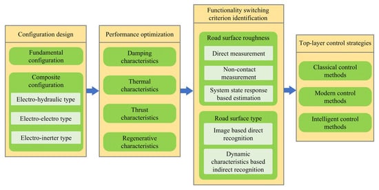
Figure 1.
Research framework.
This paper is organized as follows. Section 2 analyzes the structural features of fundamental and composite configurations of LMEERS. In Section 3, optimization pathways for the four primary operational characteristics, namely damping characteristics, thermal characteristics, thrust characteristics, and regenerative characteristics, are systematically summarized. Identification methodologies for two types of road surface information are reviewed in Section 4. A performance comparison of various top-layer control strategies applicable for LMEERS is conducted in Section 5. Section 6 discusses the existing challenges and future development trends in LMEERS. Conclusions are drawn in Section 7.
2. Configuration Design of LMEERS
2.1. Principle and Classification of Vibration Energy Regenerative Systems
According to the underlying mechanisms for the conversion of vibration energy into electrical energy, energy regenerative approaches are categorized into four types: electrostatic, piezoelectric, triboelectric, and electromagnetic [18]. Their underlying mechanisms are illustrated in Figure 2, with a comparative summary provided in Table 1. Among them, electrostatic systems exhibit a high operating frequency range but suffer from limited load-bearing capacity [19]. Piezoelectric systems are constrained by a narrow operational bandwidth [20]. And triboelectric systems face challenges in reliability and durability [21]. Consequently, these three energy harvesting approaches are not viable for engineering applications in automotive suspension systems. In contrast, electromagnetic systems operate on Faraday’s law of electromagnetic induction, converting suspension vibration energy into electricity through the relative motion between coils and permanent magnets (PMs). This mechanism exhibits high compatibility with suspension systems in terms of structural characteristics and operating principles. Furthermore, electromagnetic systems offer significant advantages, including high power output, simple control implementation, extended service life, superior environmental adaptability, and the capability of seamless switching between vibration suppression and energy harvesting.
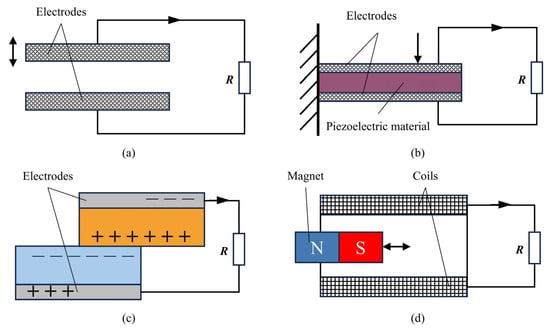
Figure 2.
Underlying mechanisms of the four energy harvesting technologies: (a) electrostatic type; (b) piezoelectric type; (c) triboelectric type; (d) electromagnetic type in Ref. [18].

Table 1.
Underlying mechanisms, core characteristics, and application status of vibration energy regenerative systems.
According to Faraday’s law of electromagnetic induction, the power generation capacity of the electromagnetic energy regenerative suspension (EERS) is closely related to the arrangement scheme, motion form, and relative velocity of PMs and coils. Based on the structure and arrangement features of the actuator, EERS can be classified into three primary configurations: rotary motor type [22], linear motor type [23], and composite type [24].
2.2. Fundamental Configuration of LMEERS
Unlike the rotary motor type, the actuator configuration of the linear motor type shares greater structural similarity with conventional hydraulic dampers. It comprises a stator and a mover, in which the mover is functionally analogous to the piston rod of a damper and connects to the vehicle body, and the stator corresponds to the damper cylinder tube and attaches to the wheel. During suspension vibration, relative linear motion occurs between the stator and mover. According to Faraday’s law of electromagnetic induction, the electric current is induced in the coils, thereby converting kinetic energy into electrical energy to achieve energy regeneration. Conversely, when alternating current is supplied to the coils, the mover generates an active force to suppress motion between the vehicle body and wheels, enabling active control functionality. It can be seen that LMEERS possesses dual functionalities of energy regeneration and active control.
Currently, linear motors exhibit diverse structural forms. Based on their topological configuration, they are classified into the cylindrical, flat-plate, and U-channel types [25,26,27], as illustrated in Figure 3. According to their operating principles, they fall into four categories: permanent magnet synchronous motors (PMSMs), alternating current induction motors (ACIMs), brushless direct current motors (BLDCs), and switched reluctance motors (SRMs) [28,29,30,31,32]. Performance comparisons of two classification schemes are presented in Table 2 and Table 3.
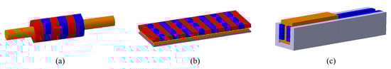
Figure 3.
Classification based on topological configuration: (a) cylindrical type; (b) flat-plate type; (c) U-channel type.
Table 2.
Performance comparison of classification scheme based on topological configuration.
Table 3.
Performance comparison of classification schemes based on operating principles.
Analysis of Table 3 reveals that PMSMs demonstrate superior efficiency, more compact dimensions, and simpler control systems compared to ACIMs. While BLDCs and SRMs exhibit certain advantages in manufacturing cost, control complexity, and reliability, both suffer from inherent drawbacks, including significant thrust ripple and lower efficiency, rendering them unapplicable for high-precision automotive suspension actuators. Furthermore, rapid advancements in motor PM materials and control technologies have substantially improved the manufacturing cost-effectiveness and control performance of PMSMs. Therefore, PMSMs have emerged as the predominant choice for actuators of automotive suspension systems.
Moreover, while cylindrical motors offer high thrust density and superior servo performance, their limited stroke and challenging heat dissipation pose significant design constraints for suspension applications. Flat-plate motors, in contrast, excel in heat dissipation and control precision, making them theoretically better suited for high-performance applications, but their significant thrust ripple and sensitivity to lateral forces could degrade ride comfort and necessitate more complex control algorithms to compensate. The choice of motor topology, therefore, is not a straightforward decision but a critical design compromise based on the prioritization of stroke, force density, thermal management, and cost.
Additionally, the arrangement schemes of two critical components, PMs and coils, exert a profound influence on motor performance [33]. Three primary classification schemes exist: the relative position of PMs and coils categorizes configurations into moving-magnet and moving-coil types, PMs magnetization orientation differentiates axial, radial, and Halbach arrays, while coil core structural form separates into slotless and slotted designs [34,35,36,37]. Schematic illustrations of these three arrangement schemes are provided in Figure 4, with performance comparisons summarized in Table 4.
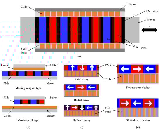
Figure 4.
Classification based on arrangement scheme of PMs and coils: (a) structural diagram of a PMSM; (b) relative position; (c) PMs magnetization orientation; (d) coil core structural form.
Table 4.
Performance comparison of classification based on arrangement scheme of PMs and coils.
2.3. Composite Configuration of LMEERS
The single-motor configuration of LMEERS cannot simultaneously ensure fundamental dynamic characteristics during energy regeneration and fail-safe properties during active control [38]. To address this limitation, composite configurations integrating complementary advantages of different types of shock absorbers are proposed to enhance the comprehensive performance of LMEERS. They are classified based on their operating principles into electro-hydraulic, electro-electro, and electro-inerter composite systems.
2.3.1. Electro-Hydraulic Composite LMEERS
The electro-hydraulic composite (EHC) configuration typically integrates a linear motor with a passive hydraulic damper or a solenoid valve damper. It utilizes the base damping provided by the latter to compensate for the shortcomings of the linear motor in damping characteristics, thereby enhancing the dynamic performance and reliability of the suspension system.
Ding et al. [39,40,41] proposed a hybrid electromagnetic actuator structure where a hydraulic damper was positioned inside a linear motor, as shown in Figure 5. In this configuration, the PM mover of the motor is rigidly connected to the damper piston rod, and the stator coils are rigidly connected to the damper cylinder barrel, thereby achieving a parallel arrangement of the damper and motor. They conducted in-depth research on the working mechanism and control scheme for this EHC configuration, revealing the influence law of damping on energy regeneration and vehicle body vibration isolation. Furthermore, a switching control strategy matching the adjustable damping of the linear motor and the fixed damping of the hydraulic damper was devised. Wei et al. [42] designed an EHC-type LMEERS applicable to MacPherson independent suspensions by employing a coaxially nested arrangement of a linear motor, a hydraulic damper, and a coil spring. The developed configuration ensures the safety and stability of the MacPherson suspension.
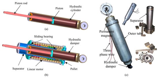
Figure 5.
Hybrid electromagnetic actuator designed in Ref. [39]: the passive hydraulic damper is placed inside the linear motor: (a) hydraulic damper; (b) hybrid electromagnetic actuator; (c) prototype of the actuator.
Acknowledging that hydraulic dampers can only provide fixed damping, a hybrid electromagnetic actuator structure integrating a linear motor with a solenoid valve shock absorber was proposed by Kou et al. [43,44]. Here, the former is utilized for active control or energy recovery, while the latter provides variable hydraulic damping by adjusting the solenoid valve opening. A multi-mode switching control strategy was designed for this composite configuration, achieving effective coordination of ride comfort, handling stability, and energy regeneration capability for suspension systems.
In contrast to hydraulic and solenoid valve dampers, which adjust damping by changing the fluid flow, magnetorheological (MR) dampers utilizing smart rheological materials can continuously adjust damping within milliseconds, offering a significantly larger control bandwidth and damping adjustment range. Consequently, MR dampers have become a current research focus in the automotive suspension field. Self-powered electromagnetic damping systems combining an energy-harvesting linear motor with an MR damper represent another common EHC configuration.
Chen et al. [45] positioned a linear motor outside an MR damper for energy regeneration, while the MR damper provided semi-active control. In this setup, the linear motor consistently operates at its maximum energy regeneration power state, and the regenerated electrical energy directly powers the MR damper, thereby achieving self-powered semi-active control. Wang et al. [46] designed a self-powered electromagnetic vibration suppression and absorption system by externally integrating a linear motor and an MR damper in parallel. Within this system, the linear motor functions for vibration absorption and energy regeneration, while the MR damper provides vibration suppression. Simulation results demonstrated that, in comparison with the sole MR suspension, this system achieved superior dynamic performances. Furthermore, the regenerated energy covered the power consumption required for semi-active control.
2.3.2. Electro-Electro Composite LMEERS
The electro-electro composite (EEC) configuration typically integrates an eddy current damper or constitutes a dual-motor structure. Ebrahimi et al. [17] proposed a hybrid electromagnetic damper featuring a highly integrated linear motor and eddy current damper. In this structure, an eddy current damper, composed of an outer conductor tube and outer magnet, is placed concentrically outside a cylindrical linear motor. When relative motion occurs in the damper, the varying magnetic field induces the eddy current within the conductor, providing an additional passive damping coefficient of 1570 Ns/m. As a result, system energy consumption was reduced by over 70%. Furthermore, Zhang et al. [47] employed a Halbach PMs array within an EEC structure to enhance the magnetic field variation rate, thereby increasing the magnitude of the induced eddy current damping. They also investigated the influence law of the dislocation ratio between the inner and outer PMs on the motor’s energy regeneration power and the composite damping coefficient.
Hu et al. [48] developed a hybrid generator integrating a sliding-mode triboelectric nanogenerator (S−TENG) with a linear motor, as depicted in Figure 6. This dual-motor structure achieved self-powering for onboard sensors without compromising vehicle ride comfort. Suda et al. [49] designed a self-powered electromagnetic active vibration isolation system for heavy-duty truck cabins with the coaxial arrangement of two linear motors. One motor operates in the generator mode to recover energy and simultaneously to provide passive electromagnetic damping. The other utilizes the recovered energy to output active control forces for suspension system. In contrast to Suda’s coaxial arrangement, Li et al. [50] employed the parallel-axis arrangement of dual linear motors, as illustrated in Figure 7. In this configuration, the primary motor functions as the actuator for active vibration suppression and energy recovery, while the secondary motor acts as a vibration absorber to absorb wheel vibration energy. Hardware-in-loop testing results demonstrated that this configuration effectively balanced the vertical dynamic performance and energy-harvesting capability, exhibiting a regeneration potential of 72 W on the B-class random road. The dual-motor structure employing a linear motor and a rotary motor was developed by Wang et al. [51].
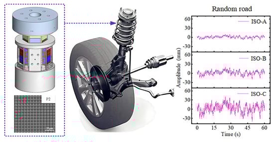
Figure 6.
Hybrid generator integrating the S−TENG with a linear motor.
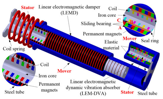
Figure 7.
Diagram of the dual linear motor actuator configuration.
2.3.3. Electro-Inerter Composite LMEERS
The electro-inerter composite (EIC) configuration introduces an inerter element into the electromagnetic system, breaking through the traditional two-element (spring-damper) parallel configuration and broadening the vibration isolation frequency band of suspension systems. Yang et al. [52] investigated the influence of series and parallel arrangements of the linear motor and inerter on the energy regeneration capability and ride comfort of suspensions, as shown in Figure 8. They concluded that the parallel arrangement is more conducive to energy harvesting efficiency, while the series arrangement benefits vehicle ride comfort. Shen et al. [53,54] integrated a linear motor with a hydraulic piston type inerter, designing a split-type EIC actuator, as illustrated in Figure 9. This design features primary and secondary hydraulic cylinders arranged side-by-side and connected via fluid circulation tubes. And the linear motor is integrated with the secondary cylinder. During suspension operation, fluid circulating between the primary and secondary cylinders generates a hydraulic inerter effect. Simultaneously, the motor can recover energy driven by the secondary cylinder piston rod or actively output electromagnetic force to the secondary cylinder. Subsequently, Hu [55] implemented active control for this EIC configuration, exploring its potential for improving vehicle dynamic performance.
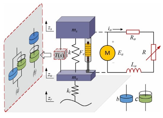
Figure 8.
Structure diagram of EIC actuator in series and parallel arrangements.
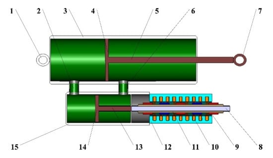
Figure 9.
Diagram of the split-type EIC actuator designed in Ref. [54].
He et al. [56] compared the performance indexes of EIC actuators with a linear motor and a rotary motor. They concluded that the ball-screw-based rotary motor combined with the inerter achieved a higher inerter–mass ratio, which was more advantageous for reducing actuator volume and mass towards commercialization. Gonzalez-Buelga et al. [57] proposed a novel electrical inerter, formed by connecting a parallel inductor–resistor circuit in series with a capacitor, and then integrated this inerter into the linear motor winding circuit to create an EIC configuration. This structure has minimal impact on the motor’s physical dimensions; however, it exhibits relatively lower energy regeneration power.
The single-motor based LMEERS configuration faces challenges in simultaneously ensuring satisfactory suspension dynamic performance during energy recovery and reliability during active control. To address these limitations, LMEERS is commonly integrated with auxiliary devices, primarily forming three composite configurations: EHC, EEC, and EIC.
- Currently, composite configurations centered around linear motors are predominantly EHC types, which underscores a fundamental engineering trade-off: reliability and “hard damping” versus energy efficiency and integration. The hydraulic component provides a fail-safe property and robust impact resistance, which is a critical advantage for automotive safety. However, this comes at the cost of energy that is intrinsically dissipated within the hydraulic fluid rather than being recovered, thereby reducing the net energy-saving potential of the entire system.
- In contrast, EEC types, exemplified by those integrating eddy current dampers, offer higher integration levels and pure electromagnetic operation but provide only “soft damping”, which may be insufficient for extreme driving conditions or failure modes. Other EEC configurations, such as the dual-motor structure, face challenges related to structural complexity and high cost, hindering commercialization prospects.
- EIC types introduce an inerter element into the electromagnetic system, breaking through the traditional two-element (spring-damper) parallel configuration and broadening the vibration isolation bandwidth. However, they encounter similar issues, including large volume, complex structure, elevated cost, etc.
Therefore, the selection of a composite configuration involves a strategic decision: prioritizing functional safety and robustness (favoring EHC) versus pursuing maximum energy regeneration and integration (favoring EEC/EIC), with the current industry trend leaning towards the former due to safety-critical considerations.
3. Performance Optimization of LMEERS
Commercial validation of LMEERS was demonstrated when Bose Corporation conducted public testing of its in-house developed suspension system in the Lexus LS400 model, revealing its capacity to recover vibration energy during compression strokes. The total energy consumption of LMEERS was reduced to merely one-third of the vehicle’s air conditioning load while excellent vibration attenuation was also achieved [58]. Similarly, BYD Auto has implemented its DiSus-Z, a linear motor electromagnetic suspension system, in the Yangwang U7 model, achieving comprehensive vehicle body control characterized by effective vibration isolation and negligible lateral tilt [59].
Extensive research substantiates LMEERS’s significant improvements in vehicle dynamic performance and energy conservation capability [60,61]. However, inherent limitations of linear motors constrain LMEERS performance in the aspects of damping, thermal, thrust, and regenerative characteristics. Addressing these deficiencies necessitates the conduction of performance optimization in terms of structural refinement, parametric optimization, and intelligent control. These three approaches all involve optimization processes, where advanced optimization algorithms serve as pivotal enablers for enhancing design efficiency [62,63,64]. Given that performance optimization for LMEERS constitutes a complex multidisciplinary, multi-objective problem, nonlinear programming methods are typically employed for systematic optimization design. The specific optimization workflow is detailed in Figure 10.
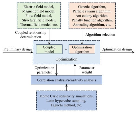
Figure 10.
Flow chart of the multidisciplinary and multi-objective optimization problem.
3.1. Optimization in Damping Characteristics
Linear motors are functionally equivalent to passive dampers when operating in energy regeneration mode. Yet, fundamentally distinct from hydraulic damping, the electromagnetic damping generated by motors constitutes “soft damping”, characterized by a significantly lower magnitude than hydraulic systems, thereby failing to rapidly attenuate suspension vibrations. For instance, the linear motor designed by Tang et al. [65] achieved a maximum damping coefficient of merely 940 N·s/m, while conventional passenger vehicles require 1500~2000 N·s/m for adequate vibration suppression. To address this deficiency, Gysen et al. [66,67] proposed embedding aluminum rings within motor stator slots. Relative motion between coils and PMs induces eddy currents in these rings, generating supplemental eddy current damping that reduces energy consumption during active control and enhances damping characteristics.
Building upon this concept, Ebrahimi et al. [17] added an additional layer of PMs concentrically outside the linear motor’s outer conductor tube. Relative stator–mover motion creates varying magnetic fields that induce eddy currents in the outer conductor tube, providing additional passive damping of 1570 N·s/m and reducing total motor mass by 53%. Tang et al. [68] further employed the Finite Element Method (FEM) to optimize motor parameters, aiming to boost power density and damping density. Additionally, they refined the motor structure by introducing a dual-layer laminated configuration and a radial PM array, which further enhanced the power density. Prototype testing results confirmed that the damping coefficient provided by the optimized linear motor met or exceeded the performance standards of conventional hydraulic shock absorbers.
It is noteworthy that the aforementioned solutions primarily focus on optimizing the linear motor structure and parameters to improve its intrinsic damping. Nevertheless, this enhanced damping fundamentally remains “soft damping”, exhibiting potential reliability concerns and failing to meet suspension dynamic demands under extreme operating conditions. Therefore, it is proposed that the reliable “hard damping” provided by hydraulic elements can be directly integrated in parallel with the linear motor to substantially increase the suspension system’s damping coefficient.
Asadi et al. [69,70] placed the linear motor inside a hydraulic damper. In this configuration, the hydraulic damper provides the base damping for the suspension system, while the linear motor recovers vibration energy. The motor’s equivalent damping can be adjusted by varying its load resistance to meet vehicle dynamic requirements under different driving conditions. Xu et al. [71] filled the interior of a linear motor with hydraulic fluid and set solenoid valves onto the piston coaxial with the motor mover. By controlling the solenoid valve opening, the damping coefficient of the hydraulic unit can be modulated. Based on this hybrid structure, the actuator can operate in three modes. In active mode or regeneration mode, the linear motor outputs electromagnetic thrust or recovers energy, while the hydraulic unit provides the base damping, ensuring suspension dynamic performance. In semi-active mode, both the motor and the hydraulic unit can simultaneously provide variable damping.
3.2. Optimization in Thermal Characteristics
Temperature rise directly deteriorates the output thrust and winding losses of linear motors, consequently degrading vibration suppression effectiveness and energy regeneration efficiency of LMEERS. In severe cases, it can even lead to PM demagnetization and winding insulation failure. Common mitigation approaches involve parametric optimization of the motor structure, implementing cooling systems, and developing thermal management control strategies.
3.2.1. Structural Optimization in Thermal Characteristics
In the aspect of parametric optimization, Wang et al. [72] proposed a bidirectional electromagnetic-thermal coupled model, accounting for the influence of variations in material thermal properties on temperature rise. With winding temperature rise and motor detent force as optimization objectives, the Response Surface Methodology (RSM) was employed for multi-objective optimization of sensitive structural parameters. The optimized design reduced winding temperature rise and electromagnetic losses by 11.02% and 17.50%, respectively. Zhu [73] established an electro-magnetic-thermal multiphysics coupled model for the linear motor, the accuracy of which was validated by a constructed temperature rise test platform. Subsequently, a neural network surrogate model was used for co-optimization of motor structural parameters. The results indicated a 6.3% reduction in the optimized coil peak temperature.
BYD Auto has conducted structural refinement of LMEERS by arranging various cooling systems in order to improve its thermal characteristics. Several liquid-cooling schemes have been designed, such as installing external radiators [74] and incorporating internal heat exchange cavities or cooling chambers within motors [75,76,77]. An air-cooling solution featuring a novel rectifier design capable of generating stable, high-speed airflow within the motor housing for stator cooling was also developed [78].
3.2.2. Thermal Management
For the dynamic operating environment of automotive suspensions, precise tracking of the linear motor’s transient temperature response is essential for implementing effective thermal management and improving the utilization efficiency of the motor’s electromagnetic output. Available monitoring methods include sensor-based and model-based approaches. The former involves direct sensor placement within motors but poses significant challenges regarding system cost, reliability, and signal accuracy. Therefore, research should prioritize the latter approach [79,80].
Common thermal monitoring models can be categorized into Lumped Parameter Thermal Networks (LPTNs) or numerical modeling. Both methods can effectively predict motor temperature distribution [81,82]. Lu et al. [83] investigated the thermal distribution of a PM linear motor during operation on the basis of LPTN. This enabled real-time optimization of the coolant flow rate in the liquid-cooling system. Furthermore, the optimal relationship between the short-time large current and working time, as well as the optimal duty cycle for the drive current, were determined. Chow et al. [84,85] modeled the motor with the Finite Difference Method (FDM), as shown in Figure 11, to calculate the internal heat transfer. Experiments confirmed the high accuracy of this method for temperature prediction.
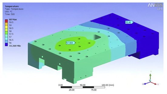
Figure 11.
Temperature profile of the linear motor under steady-state thermal simulation in Ref. [84].
3.3. Optimization in Thrust Characteristics
The thrust output of a linear motor is proportional to its volume, while the compact installation space within a suspension system imposes significant constraints on the dimension design of motors requiring high thrust. Furthermore, several factors such as end effects and cogging effects cause thrust ripple, which deteriorates the positioning accuracy and operational stability of motors [86,87,88]. To optimize the thrust characteristics of linear motors, three approaches are typically employed, namely structural refinement, parametric optimization, and intelligent control.
3.3.1. Structural Optimization in Thrust Characteristics
Regarding refinement and optimization, for the primary unit, Refs [89,90,91] proposed to optimize the primary core length to reduce end forces. Refs [92,93] demonstrated that incorporating an auxiliary pole structure on the primary unit could effectively suppress thrust ripple. Makki et al. [94] investigated the influence of primary core slotting design on the magnetic reluctance force. A tubular linear PMSM featuring a double primary structure was designed by Wu et al. [95,96]. The electromagnetic characteristics of the dual primaries was superimposed, and the end tooth structure was optimized, which effectively suppressed the even harmonics within the detent force, thereby reducing motor thrust ripple. The optimized structure exhibited low thrust ripple and excellent working performance. Zhang et al. [97,98] proposed a modulation method for cogging force and end force based on the destructive interference theory. Accounting for both cogging and end effects, they established an integrated subdomain analytical model to optimize the primary core structural parameters, thereby reducing detent force. The proposed method achieved a thrust ripple below 1.5%.
In addition to considering the primary structure, Yan et al. [23] also investigated the influence of secondary PM parameters on thrust ripple. Multi-objective optimization with the Taguchi method and RSM resulted in an 11.9% increase in average thrust and a 76.6% reduction in ripple for the optimized motor. A novel skewing pole structure for PM was proposed by Li et al. [99], which further reduced thrust ripple. Xu et al. [100] suggested employing the Halbach array for PM to suppress thrust ripple. Refs [101,102,103] investigated the impact of PM shape on thrust performance, such as the arc-shaped PMS shown in Figure 12, while complex shapes increased the manufacturing complexity. Cheng [104] discovered that motor detent force would reach its minimum when the number of slots and poles were coprime. Lu et al. [105] further clarified that in single-sided linear motors, thrust characteristics are superior when the slot–pole combination differs by 1 or 2. For double-sided structures, thrust density is higher when the slot–pole combination differs by 1.
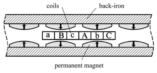
Figure 12.
Arc-shaped PMs mentioned in Ref. [101].
3.3.2. Intelligent Control in Thrust Characteristics
Implementing advanced control strategies to compensate for linear motor behavior and improve dynamic response proved to be an effective approach for detent force suppression. Common suppression strategies include active disturbance rejection control [106,107,108], sliding mode control [109,110], predictive control [111,112,113], and iterative learning control [114,115,116].
Kim et al. [117] compensated for thrust ripple with a feedforward controller. Zhang et al. [118] designed a Proportional Resonant Internal Model Extended State Observer (PR-IMESO) specifically targeting detent force. This designed disturbance observer possessed excellent capabilities of observing and compensating for detent forces, and effectively suppressed thrust ripple caused by other unmodeled factors. Model-based feedforward and observers do not change the controller structure and require less computational resources, but their optimization effectiveness is limited in high-frequency, high-speed environments. In contrast, intelligent control strategies, such as neural network and iterative learning, offer superior compensation for thrust ripple. However, they inherently suffer from substantial computational burdens, potentially compromising the real-time performance of the control system.
3.4. Optimization in Regenerative Characteristics
The energy regeneration power in energy recovery mode and the electromagnetic thrust in active control mode are fundamentally determined by the air-gap magnetic flux density between the primary and secondary components. To enhance motor energy regeneration efficiency, optimization efforts are focused on three aspects: structural refinement, parametric optimization, and intelligent control.
3.4.1. Structural Optimization in Regenerative Characteristics
Regarding structural refinement, the layout of PMs and coils is primarily optimized. In the aspect of PM design, Gupta et al. [119] designed an electromagnetic energy regenerative damper featuring a coaxial arrangement of inner and outer dual-layer annular PMs for improving regenerative characteristics. Although increasing the number of PMs could readily enhance the air-gap flux density, it concomitantly increases the actuator’s volume and weight, hindering practical application.
To address this limitation, Halbach [120] innovatively proposed a novel PM array. Unlike conventional arrays, adjacent PMs in this array are magnetized at 90° angles relative to each other. This design significantly strengthens the magnetic field on one side while nearly eliminating it on the opposite side, thereby achieving high field strength within a compact volume. Zhu et al. [121,122] investigated the application potential of Halbach arrays for vibration energy recovery. Simulation results demonstrated that single-layer and double-layer Halbach arrays increased the energy regeneration power of linear motors by 40% and 88%, respectively. Dai [123] compared the air-gap flux density of different arrays on the basis of FEM. As shown in Figure 13, the Halbach array exhibited the highest density. The Halbach-like array was designed by Xiong et al. [124] to increase motor energy regeneration power. Additionally, Kopylov et al. [125] found that implementing a back-iron architecture for PMs yielded higher energy harvesting power.
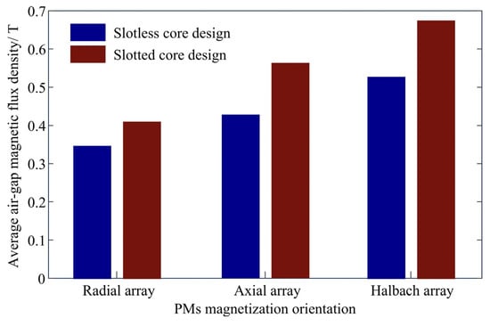
Figure 13.
Air-gap magnetic flux density of different PM arrays and coil core slots.
Additionally, regarding coil layout, factors such as turn number, layer number, phase number, and the core slotting design also influence energy recovery power. Tang et al. [65] indicated that a larger winding phase number could increase power. Figure 13, above, also illustrates that the slotted core design yields a greater magnetic flux density.
For parametric optimization, Hasani et al. [126] proposed an optimization method based on the electromagnetic damping model to improve motor energy regeneration efficiency. Abdelkareem et al. [127] conducted frequency-based parametrical bandwidth sensitivity analyses on suspension vibration energy recovery potential with Monte Carlo sensitivity simulations. The correlation between energy-harvesting potential and various suspension parameters were revealed, providing the theoretical foundation for subsequent parametric optimization and facilitating the conceptual design of EERS.
3.4.2. Intelligent Control in Regenerative Characteristics
Once the topology and parameters of LMEERS are finalized, efficient and reliable intelligent control strategies are essential to fully exploit its energy regeneration potential. Li et al. [128] proposed a pavement-level-based switching control strategy for LMEERS. Its core logic involves adjusting the control parameters of the top-layer controller according to the road profile to ensure the maximum energy harvesting efficiency under high-frequency excitation. Simulation results showed that this switching strategy improved regenerative efficiency by 30.5%. Azmi et al. [129] designed an optimal control strategy based on a continuous predictive approach. The energy regeneration power increased by 31% due to the suspension control focus steered towards high-efficiency regenerative regions by adjusting weighting coefficients. The time-delay control was employed by Wu et al. [130] to enhance the energy recovery capability. The existing literature demonstrates that the introduction of active control can effectively improve energy harvesting potential. However, it is noteworthy that extracting excessive energy from suspension vibration will degrade other performance indexes, highlighting an inherent trade-off between the dynamic performance and energy regeneration capability of LMEERS.
3.5. Emerging Optimization Methods
While the optimization methods discussed in the preceding sections have significantly enhanced the comprehensive performances of LMEERS, they often face inherent limitations. These include the computational complexity of high-fidelity multi-physics models, challenges in handling system nonlinearities and uncertainties in real-time, and the difficulty in achieving a globally optimal trade-off between dynamic performance and energy regeneration capability. Recent advancements in Artificial Intelligence (AI) and Digital Twin (DT) technologies offer a transformative paradigm to overcome these limitations and unlock new frontiers in LMEERS performance optimization [131,132].
DT technology, characterized by the creation of a high-fidelity virtual replica of the physical suspension system, moves beyond the traditional static modeling. This cyber-physical system synchronizes with its physical counterpart in real-time via sensor data, enabling unprecedented capabilities for optimization [133,134,135,136,137]. The DT framework integrates high-fidelity electromagnetic, thermal, and structural models, facilitating the virtual prototyping and design validation, real-time performance prediction, and closed-loop online calibration. Prusa et al. [138] conducted a comparative analysis of the performance differences between DT technology and the traditional Finite Element Method (FEM) in the development of linear motors, arguing that DT can simultaneously achieve both simulation accuracy and real-time capability. This led to the conclusion that DT is highly important for the motor development process. Luo et al. [139] proposed a data-driven DT method for real-time estimation of the motor operating temperature, with experimental results demonstrating the method’s effectiveness in achieving thermal management for motors. Antonelli et al. [140] developed a DT of a suspension system after performing nonlinear modeling, which was utilized for the development and optimization of the suspension control system. Furthermore, online calibration of the controller was also conducted on the DT.
Meanwhile, AI-driven methodologies are revolutionizing control and optimization strategies [141,142,143,144]. Deep Learning (DL), particularly through deep neural networks, excels at identifying complex, non-linear patterns from operational data [145,146]. DL can be employed to develop data-driven surrogate models that approximate the system’s dynamics with less computational cost than full physical models, or to enhance road information identification algorithms for more precise functionality switching [147,148]. Iwata et al. [149] employed a pre-trained deep learning model to predict the degree of influence of transitions from air to magnetic materials in a PMSM, thereby facilitating the topological optimization of the motor. Both the development efficiency and the motor’s electromagnetic and mechanical performance were significantly improved. Khan et al. [150] introduced a novel method using deep learning to predict the efficiency map of motor drives, which demonstrated higher accuracy and efficiency compared to FEM. In addition, this method is proven to be applicable to the design and optimization processes of motors.
The convergence of DT and AI creates a powerful symbiotic relationship where DT provides the realistic environment necessary for training and validating AI algorithms, while AI provides the intelligent core to analyze data and make decisions within the DT framework. This integrated approach promises a future where LMEERS can autonomously self-optimize its performance in real-time, achieving a truly adaptive and intelligent suspension system. Although these technologies are still immature in their application to LMEERS, they signify a pivotal shift from conventional methodologies towards a more holistic, data-driven, and self-adaptive optimization paradigm, setting a clear direction for future research and development.
In summary, due to performance limitations inherent in the linear motor, LMEERS exhibits shortcomings in damping, thermal, thrust, and regenerative characteristics. Three aspects of structural refinement, parametric optimization, and intelligent control are typically focused on to improve the comprehensive performance of LMEERS.
- Damping characteristics is typically enhanced by integrating the eddy current or hydraulic damping modules.
- Parametric optimization and implementing cooling systems are simple and effective approaches to mitigate motor temperature rise.
- Thrust and regenerative characteristics, being critical to the functional behavior of LMEERS, require a comprehensive set of approaches for improvement.
- Emerging optimization methods, such as DT and AI, demonstrate substantial application potential, representing a promising and critical direction for future research.
4. Functionality Switching Criterion Identification of LMEERS
An inherent trade-off exists between the energy regenerative capability and dynamic performance of LMEERS. Consequently, the working modes of LMEERS must be judiciously switched according to driving conditions to balance its dual functionalities of energy regeneration and active control. Road excitation, as the primary input source generating vibration for suspension systems, also constitutes a critical component of the vehicle’s driving conditions. Therefore, road surface information serves as the most appropriate switching criterion for determining whether LMEERS should prioritize active control or energy recovery [18].
Furthermore, the extraction and identification of road surface information can offer more precise and rational front-end decision-making for subsequent top-layer control. This ensures the organic combination and efficient coordination between energy regeneration and active control, ultimately achieving the control objective of optimal overall performance across all road conditions. With the rapid development of high-level autonomous driving, multi-sensor fusion-based environment recognition technologies are maturing daily. This maturation provides the technical foundation for LMEERS to perform functionality switching based on road surface information. Hence, researchers worldwide have begun to prioritize road surface information as a key criterion for LMEERS mode switching.
For vertical dynamic control of suspension systems, road surface information primarily comprises road surface roughness and road surface type.
- Road surface roughness, defined as the random variation in road surface profile (as illustrated in Figure 14), is the direct vertical excitation input to the wheels [151]. Through the tire–suspension–body transmission path, it induces vibrations. These vibrations influence the vehicle’s demand for either dynamic performance or energy regeneration capability—essentially determining which functionality mode is the optimal choice at any given moment. Therefore, road surface roughness is the core road information considered during LMEERS functionality switching, particularly in single-wheel suspension application scenarios.
- Regarding the road surface type, it reflects the statistical characteristics of road surface roughness, typically serving as prior knowledge to assist in estimating road surface roughness [152]. The fundamental methods for road surface information identification are summarized in Figure 15. The identification methods of road surface roughness are primarily divided into three categories, namely direct measurement, non-contact measurement, and system state response-based estimation [153,154,155]. And road surface type identification methods are categorized into two main classes, namely image-based direct recognition and vehicle dynamic characteristic-based indirect recognition [156,157].

Figure 14.
Road surface roughness visualization: (a) vertical road surface profile; (b) contact between a rough road surface and tire (the road vertical profile is exaggerated for better visualization).
Figure 14.
Road surface roughness visualization: (a) vertical road surface profile; (b) contact between a rough road surface and tire (the road vertical profile is exaggerated for better visualization).


Figure 15.
Fundamental methods for road surface information identification.
Figure 15.
Fundamental methods for road surface information identification.

4.1. Identification of Road Surface Roughness
4.1.1. Direct Measurement Methods
Direct measurement methods utilize specialized equipment, such as road roughness meters, installed on or connected to vehicles to directly measure the road surface profile in the case of maintaining continuous contact with the ground [158,159]. Guo et al. [160] conducted a comparative analysis of various measurement techniques, concluding that direct measurement methods could yield high-precision road surface roughness data, thereby accurately reflecting road surface profile information.
A novel compact pavement profilometer was employed by Abulizi et al. [153] to conveniently collect data for assessing the roughness condition of public roads. Lushnikov et al. [161] compared the operational characteristics and measurement accuracy of several profilometers used for measuring road surface longitudinal roughness. Currently, a widely adopted road roughness meter within the industry is the Longitudinal Profile Analyzer (LPA) developed by the Laboratoire Central des Ponts et Chaussées (LCPC) in Nantes, France. Its structure is shown in Figure 16. This instrument can accurately measure road surface profiles with amplitudes around ±100 mm and wavelengths spanning 0.5–20 m to 1–50 m. Since that the LPA feeler wheel maintains contact with the road surface via a spring and damper system, the spring stiffness and damper damping coefficient influence the amplitude–frequency characteristics of the LPA, thereby affecting the measurement accuracy within its resonance frequency range [162]. Besides the French LPA, other commonly applied road roughness meters include the articulated multi-wheeled profilograph developed by the UK’s Transport Research Laboratory (TRL) [163], and the vibratory cumulative measuring device adopted by the US Federal Highway Administration (FHWA) [164].
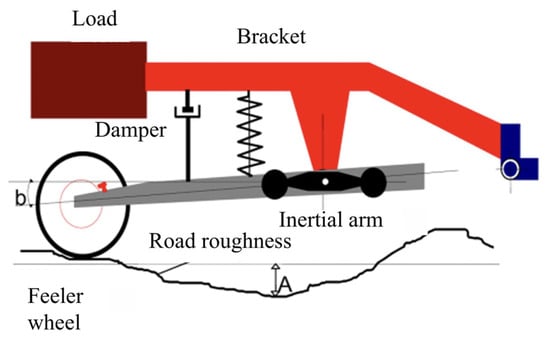
Figure 16.
Longitudinal Profile Analzser developed in France.
Limitations inherent in the structure and installation requirements of road roughness meters result in the poor transplant ability of these instruments. Furthermore, the measurement process necessitates that vehicles must travel at relatively low speeds. Therefore, direct measurement methods based on specialized equipment are mainly applied to pavement maintenance and repair and inapplicable for real-time road information acquisition on conventional vehicles.
4.1.2. Non-Contact Measurement Methods
Non-contact measurement methods operate based on the inertial reference principle. Distance sensors (e.g., Light Detection And Ranging (LiDAR), Radar) or vision sensors (e.g., optic camera) installed on vehicles are utilized to directly measure road surface profile [165]. With the advancement of automotive intellectualization, these methods exhibit broad application prospects. Babu et al. [154] proposed a novel semi-empirical model for road surface roughness identification based on the high-resolution airborne Polarimetric Synthetic Aperture Radar (PolSAR). The measurement results demonstrated high agreement with ground truth data. Furthermore, the proposed model is adaptable to lower-performance SAR systems, thereby reducing identification costs. Gao et al. [166] applied high-precision point cloud data from a 3D LiDAR to measure urban pavement roughness. This approach accurately estimated the International Roughness Index (IRI) values of actual roads and the distribution characteristics of their spatial roughness. The LiDAR data-based identification algorithm developed by Kumar et al. [167] estimated pavement roughness by calculating the profile residual values between the LiDAR points and road surface mesh. Their experimental results validated the algorithm’s effectiveness. Blasiis et al. [168] designed the identification workflow illustrated in Figure 17. It demonstrates the minor deviations between road surface profiles calculated from LiDAR data and those directly acquired by a profilometer.
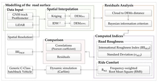
Figure 17.
Identification workflow of a non-contact measurement method based on LiDAR.
Current research indicates that LiDAR-based non-contact measurement methods achieve high accuracy but they impose a significant cost burden on vehicles. Consequently, the relatively lower-cost optic cameras attain expanded concerns. Khalifeh et al. [169] constructed 3D road surface models according to the color and depth images captured by cameras. The road profile under a single wheel track was then extracted to ultimately derive the IRI value. This method offered high measurement accuracy and low equipment costs. Aleadelat et al. [170] employed a low-cost depth camera to estimate IRI values, achieving accuracy of 83%.
Although non-contact measurement methods show high identification accuracy and good transplant ability, enabling on-board measurement on conventional vehicles, they necessitate additional expensive sensors and image processors. Moreover, due to lengthy processing times, measurement effectiveness remains constrained by vehicle speed (typically 20~100 km/h). Additionally, commonly used LiDARs and cameras exhibit poor environmental adaptability, making it difficult to guarantee their measurement accuracy under rainy or snowy weather [171].
4.1.3. System State Response-Based Estimation Methods
To address the limitations of direct measurement methods, such as poor transplant ability, and those of non-contact measurement methods, such as high cost and poor environmental adaptability, estimation methods based on vehicle dynamic responses using low-cost sensors commonly equipped in conventional vehicles have garnered significant attention. The type of suspension signals used obviously impacts the applicability and estimation accuracy of different state response-based estimation methods.
Acceleration is one of the most common signals and boasts the highest sensor equipment rate in suspension systems. It directly reflects vehicle vibration intensity; hence, identification methods based on acceleration signals have been extensively researched. Liu et al. [172] designed an online road level identification algorithm based on vehicle body acceleration signal, with its principle illustrated in Figure 18. First, they constructed an inverse dynamic model of a quarter-car suspension system with the adaptive neural fuzzy network, then the time-domain road surface profile estimator was designed. Finally, the frequency-domain road level estimator was developed based on Power Spectral Density (PSD) estimation. Experimental results demonstrated that this algorithm achieved estimation accuracy exceeding 90% across various random roads and exhibited excellent adaptability to varying vehicle speed. Liu et al. [155] proposed a speed-decoupled road level identification method. Vehicle body and wheel accelerations were selected as input signals, and an improved Least-Squares Method (LSM) was applied to obtain pure spatial-domain pavement roughness parameters independent of vehicle speed, with estimation accuracy exceeding 95%. Axle acceleration was utilized by Ngwangwa et al. [173] to design a road identification method based on an artificial neural network for mining trucks. Notably, this method exhibits high estimation accuracy for discrete road obstacles, such as bumps, depressions, and potholes. Based on the Long Short-Term Memory (LSTM) model, Im et al. [174] designed a deep learning identification system for entire vehicles to estimate the roughness of unknown roads. This method worked with the data from accelerometers and gyroscopes at the vehicle’s center of gravity without a physical suspension system model, rendering it more lightweight and efficient.
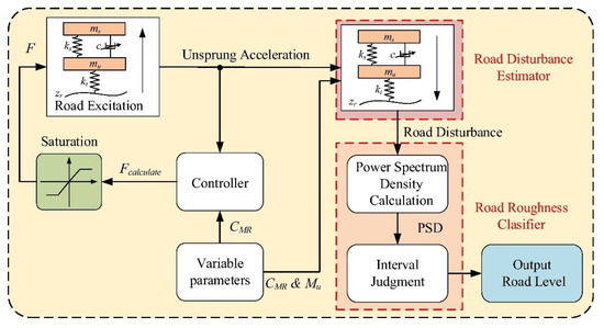
Figure 18.
Principle of the online identification algorithm for road level.
In addition to the acceleration signal, suspension working stroke is another readily measurable vibration characteristic parameter. Guo et al. [175] proposed that suspension working stroke has the potential to be employed for pavement roughness identification. For this purpose, a novel road level evaluation index was defined, and its explicit expression in terms of suspension working stroke and vehicle speed was derived. Gong et al. [176] introduced the new Relative Roughness Index (RRI) according to IRI as the basis for identifying complex road roughness encountered by heavy-duty rescue vehicles. Furthermore, with suspension working stroke as the sole input, the road level identification method based on a Takagi–Sugeno (T-S) fuzzy controller was developed. A discrete Kalman observer considering unknown inputs was designed by Kang et al. [177]. Suspension working stroke, vehicle body acceleration, and wheel acceleration were selected as the state variables for online road surface roughness estimation. Due to significant simplifications of suspension system nonlinearities, this method exhibited certain identification errors. To address this limitation, Kim et al. [178] incorporated a vehicle parameter identification module to enhance the Kalman observer’s accuracy. Focusing on a half-car model, Li et al. [179] selected eight suspension signals as inputs, namely suspension working stroke, vehicle body acceleration, wheel acceleration, vehicle body pitch angular velocity, and displacement, and then employed the orthogonal experimental design to analyze the performance of four typical neural networks, namely BackPropagation (BP), Radial Basis Function (RBF), wavelet, and Nonlinear AutoRegressive with eXogenous inputs (NARX). Simulation results verified NARX as the optimal neural network for road roughness identification. Wang et al. [180] investigated the application potential of pavement roughness identification for multi-axle heavy vehicles. Using displacement and oil pressure signals from hydro-pneumatic suspension cylinders as response signals, a Support Vector Machine (SVM) trained by both model and real vehicle data was employed to recognize the road level.
System state response (e.g., acceleration, suspension working stroke)-based road surface roughness identification can be categorized into three core methodologies. The first type is the dynamic model-based inverse method, in which the road profile is directly estimated from sensor data according to the dynamic relationship between vehicle body and wheels. The second type is the state observer method, in which an observer designed based on the vehicle physical model fuses multi-sensor data to simultaneously estimate road information and suspension states. In contrast, the last type bypasses physical modeling and directly establishes end-to-end mapping from sensor data to road roughness, which is referred to as the data-driven method. A comparative analysis of these three methods is presented in Table 5.
Table 5.
Performance comparison of three system state response-based estimation methods.
Road surface roughness identification methods have been primarily classified into three major categories: direct measurement methods, non-contact measurement methods, and system state response-based estimation methods. Each category possesses distinct characteristics and respective strengths. Table 6 summarizes the features and applicable scenarios of these three identification methods.
Table 6.
Performance comparison of three road surface roughness identification methods.
4.2. Identification of Road Surface Type
One fundamental function of suspension systems is to transmit and dynamically distribute the vertical loads acting on the tires. This ensures that tires maintain continuous contact with uneven road surfaces, thereby maximizing effective adhesion utilization between the tires and pavements. Furthermore, this enhances the traction performance, braking performance, and handling stability of vehicles. The same pavement under different environmental conditions, or different types of pavements under the same conditions, exhibit distinct surface characteristics. For instance, road adhesion significantly deteriorates on wet or icy surfaces, while gravel roads present a broadband random excitation. In addition, discrete pavement features, such as potholes, bumps, and cracks, impose more stringent demands on suspension system performance. Therefore, research on road surface type identification, followed by adaptive switching of suspension operating modes, constitutes a critical pathway for ensuring that vehicles maintain superior dynamic performance and energy regeneration capability even under complex road conditions. Additionally, different road types typically exhibit characteristic statistical features of the roughness, which can serve as prior knowledge to assist in estimating road surface roughness. Image-based direct recognition methods and vehicle dynamic characteristic-based indirect recognition methods are typically employed in the estimation of road surface types.
4.2.1. Image-Based Direct Recognition Methods
Direct recognition methods comprehensively utilize sensors, such as optic cameras and imaging radar, to acquire road surface images. Target information is then directly identified through image processing [181]. Sabery et al. [156] employed the Convolutional Neural Network (CNN) to classify road surfaces with images captured by an imaging radar. Liu et al. [182] also utilized the CNN to process the collected road surface image data via cameras for type identification. The recognition accuracy exceeded 99.9% for different road surfaces, with a processing time of approximately 9.5 ms per image. Subsequently, the control parameters of a semi-active control strategy were optimized based on the identified road information, enabling the suspension system to achieve superior dynamic performance. Zhao et al. [183] proposed a vision-based road classification method with the recognition accuracy of 94.84%. This method extracted texture features from road surface images captured by a camera, and then a deep learning classification model incorporating specific training strategies was employed to infer the road surface type. Furthermore, advancing this approach, Zou et al. [184] combined transfer learning with the Visual Geometry Group Network (VGGNet) model to design a network architecture specifically tailored for road classification. Its processing workflow is illustrated in Figure 19. Compared to other classical network models, this approach has significantly improved identification accuracy and training speed, making it applicable for preemptive perception of road types. The recognition method combining visual data with a Deep Neural Network (DNN), developed by Šabanovič et al. [185], exhibited high identification efficiency and was capable of monitoring every half-meter of road surface at vehicle speeds of 100 km/h.
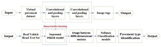
Figure 19.
Transfer learning process for pavement classification recognition based on the improved VGGNet-16 model.
For suspension control, discrete road surfaces, such as potholes, bumps, and cracks, significantly impact ride comfort and driving safety. Therefore, with road structural features as classification criterion, vision sensor-based road type identification methods have also been investigated. These methods aim to preemptively adjust suspension control parameters, thereby mitigating the deterioration of vehicle dynamic performance under transient excitations. Wang [186] proposed a semi-global block matching algorithm to construct a road profile model from 2D images captured by binocular cameras, and then extracted the road slope and bump features to train a multi-class SVM. As a result, the SVM could identify four characteristic road types: uphill, downhill, flat roads, and speed bumps.
The effectiveness of image-based direct recognition methods hinges on the efficiency of the image processing techniques. Common techniques are categorized into traditional methods and deep learning methods [187,188]. The former involves two steps: feature extraction and classifier construction. These typically require manual intervention, consuming significant labor and time resources, and exhibit limited performance in complex scenarios [189,190]. In contrast, deep learning methods can directly process raw data. They enable machines to autonomously learn feature representations and abstractions, thereby avoiding tedious manual feature construction and enhancing image recognition accuracy [191,192].
4.2.2. Vehicle Dynamic Characteristic-Based Indirect Recognition Methods
Direct recognition methods are inherently dependent on image quality, and their operational performances under harsh environmental conditions are difficult to guarantee. In addition, when actual driving conditions deviate from the algorithm training conditions, the estimation accuracy for road surface type tends to decrease. In contrast, vehicle dynamic characteristic-based indirect recognition methods exhibit superior environmental adaptability. Their fundamental principle is illustrated in Figure 20. Additionally, dynamic characteristic-based classification models inherently imply the interaction mechanics between the vehicle and the road surface. Therefore, their identification results possess greater applicability value for vehicle control.
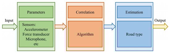
Figure 20.
Fundamental principle of vehicle dynamic characteristic-based indirect recognition methods.
Ward et al. [157] posited that the wheel acceleration directly reflected the road profile, thus selecting this signal as the algorithm input and employing an SVM for the identification. Notably, the vehicle speed was decoupled by performing spatial estimation on the road profile. Wang et al. [193] utilized accelerometers to capture triaxial accelerations during tire rolling, and then extracted time-domain and frequency-domain statistical features from the longitudinal and lateral acceleration signals. Following dimensionality reduction via principal component analysis, an SVM was used to classify and train the feature parameters, ultimately achieving road type estimation. With wheel vertical forces selected as the response signals, Yang et al. [194] applied wavelet packet transform for feature extraction, followed by an SVM for unpaved road classification. Zhao [195] selected wheel speed fluctuation, rolling resistance, and vertical acceleration as inputs and adopted the SHapley Additive exPlanations (SHAP) approach to elucidate the correlation between dynamic features and road surface types. A Random Forest (RF)-based road classifier was subsequently designed, and its recognition accuracy and recall rate both exceeded 93%.
The acoustic footprint varies significantly across different road types, and the frequency of tire–road noise on the same surface differs under varying moisture levels. On this basis, Alonso et al. [196] proposed a method to identify the dry/wet state of asphalt pavements by measuring tire–road noise. Paulo et al. [197] investigated the correlation between the acoustic signals generated at the tire–road interface and the road profile based on statistical learning methods. Combining Bayesian analysis with a neural network for road type classification achieved accuracy exceeding 90%. Furthermore, Kalliris et al. [198] evaluated the practical performance of various machine learning algorithms for road type identification using tire noise. Results demonstrated that second-order and third-order SVMs yielded the best performance.
The working principle underlying indirect road type identification is fundamentally identical to the data-driven method for road surface roughness identification introduced in Section 4.1.3. Both bypass system modeling to directly establish a mapping relationship between sensor data and road characteristics (roughness or type). However, the sensors employed for road type identification are not limited to those typically deployed within suspension systems.
To utilize the complementary strengths of both direct and indirect methods, multi-sensor fusion-based road type identification methods have been proposed. Wang et al. [199] introduced an identification method fusing the features of mechanical and visual sensor data. This approach first reconstructed the road profile via a vehicle dynamic model with wheel acceleration and vehicle speed information. Subsequently, feature extraction and classification of road surface images captured by cameras were conducted. Finally, the data features from all sensors were fused for road type identification. Experimental results revealed that identification accuracy based on the sole dynamic characteristics was relatively low, averaging 67%, while sole image-based identification averaged 88% accuracy. Notably, multi-sensor fusion significantly improved the average accuracy to 90%, with enhanced reliability and adaptability. Although multi-sensor fusion offers higher accuracy and reliability, providing a novel direction for road information identification research, vigilance is required regarding the “barrel effect” (where overall performance is limited by the weakest sensor), introduced by multiple sensors.
4.3. Decision-Making Algorithms for Functionality Switching
Accurate identification of road surface information (roughness and type) serves as an essential input for suspension control, but it is the decision-making algorithms that act as the intelligent gateway, determining the functional mode of LMEERS. The core objective of these algorithms is to resolve the inherent conflict between vibration isolation and energy harvesting by the intelligent switching between active control and energy regeneration modes based on real-time driving conditions. The prevailing decision-making algorithms can be categorized as follows.
- Rule-Based Threshold Switching: This is the most straightforward approach, where predefined thresholds on identified road indexes (e.g., IRI [176], root mean square of suspension state variables [177,178,179]) trigger functionality switching. For instance, if the road roughness exceeds a certain threshold, indicating poor road conditions, the algorithm prioritizes active control to ensure ride comfort and driving safety. Conversely, on smooth roads (low roughness), it switches to energy regeneration mode to maximize energy recovery [19,148]. While simple and computationally efficient, this method lacks flexibility and can lead to frequent or oscillatory switching if thresholds are not carefully tuned for complex road scenarios.
- Fuzzy Logic Inference: Fuzzy Logic Control (FLC) is highly suited for this application due to its ability to handle imprecise inputs with expert knowledge. The identified road information (e.g., “smooth”, “rough”) and vehicle states (e.g., “high speed”, “low speed”) are fuzzified and processed through a set of IF-THEN rules formulated by domain experts to output a decision or a continuous weighting factor between the two functionalities [64,200]. For example, a rule could state: “IF road is very rough AND vehicle speed is high, THEN prioritize active control.” This method offers smoother transitions between modes and better handles the ambiguity in road classification compared to rule-based thresholds.
- Learning-Based Adaptive Strategies: With the advancement of onboard processing power, data-driven learning algorithms are emerging for more intelligent and predictive switching. These strategies can adapt the switching policy online based on historical performance or driver preferences. Reinforcement Learning (RL) is a promising framework where an agent learns an optimal policy (switching strategy) by maximizing a reward function that balances ride comfort, driving safety, and energy recovery efficiency [201]. Neural network can also be trained to map identified road features and vehicle states directly to the optimal functionality mode [202,203]. Although these methods promise superior performance and adaptability, they require significant computational resources and extensive training data.
The selection of decision-making algorithms involves a trade-off between computational complexity, performance, and ease of calibration. The ultimate goal is to seamlessly integrate this algorithm with the top-layer control strategies (in Section 5) to form a cohesive hierarchical control architecture that fully exploits the potential of the dual functionality of LMEERS.
In summary, in-depth investigations into road surface information identification have been conducted, establishing it as a crucial switching criterion between the dual functionalities of energy regeneration and active control for LMEERS. Road surface information primarily encompasses road surface roughness and road surface type, typically identified with two on-vehicle approaches, namely image-based methods and dynamic response-based methods.
- The former offers preemptive perception of the road ahead and high identification accuracy but suffers from high equipment costs and poor environmental adaptability.
- The latter provides superior robustness and cost advantages, yet struggles to identify complex road surfaces.
- Multi-sensor fusion-based road information identification methods, capitalizing on the advantages of both methods, represent the future direction for on-vehicle solutions, contingent upon further reductions in sensor costs.
5. Top-Layer Control Strategies of LMEERS
Structural design and top-layer control constitute two pivotal aspects in LMEERS development. The former establishes the physical foundation and defines performance boundaries for the latter, while the latter exploits application potential and compensates for inherent deficiencies of the former. This synergy fundamentally determines the ultimate performance ceiling of LMEERS systems. Currently, extensive and in-depth research has achieved profound advancements in structural design and performance optimization, establishing robust feasibility for active control and energy regeneration within current configurations. Consequently, the imperative now shifts toward developing structure feature-based top-layer control methodologies to maximize operational efficiency across diverse working environments. Top-layer control strategies applicable for LMEERS are typically categorized into three types, namely classical control methods, modern control methods, and intelligent control methods.
5.1. Classical Control Methods
Classical control methods are typically applicable for single-input single-output linear time-invariant systems, the core tools of which are the frequency-domain analysis and transfer function models. These have the advantages of intuitiveness, practicality, and outstanding engineering solution capabilities [204,205]. Presently, the classical control methods commonly applied to LMEERS include skyhook control, groundhook control, and PID control.
5.1.1. Skyhook and Groundhook Control
Skyhook control was first proposed by Karnopp [206] in the 1974s. Its operating principle involves virtually connecting the vehicle body to an ideal inertial sky via a damper, thereby suppressing vertical vibrations of the sprung mass. This approach circumvents suspension nonlinearities by requiring the actuator to output a force proportional to the absolute velocity of the sprung mass but in the opposite direction. However, since the “ideal sky” is physically unrealizable, actuators mounted between the vehicle body and wheels must emulate this skyhook force, which inevitably amplifies unsprung mass oscillations. To address this limitation, Hong et al. [207] developed a modified skyhook strategy incorporating supplemental passive damping to suppress wheel vibrations, thereby effectively balancing ride comfort and handling stability. Groundhook control operates on a similar principle but targets vibration suppression of the unsprung mass. Comparative ideal models of both strategies are illustrated in Figure 21.
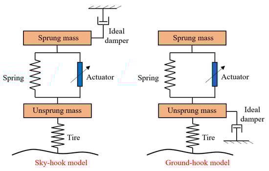
Figure 21.
Ideal models of skyhook and groundhook control strategies.
Ding et al. [208,209] designed an energy-saving modified skyhook algorithm for an electro-hydraulic composite LMEERS. The skyhook damping in the algorithm was provided by the linear motor while the passive damping was delivered by the hydraulic damper. This algorithm matching damping and regenerative characteristics of the actuator realizes the superior satisfaction of LMEERS control requirements, where ride comfort is obviously improved without substantial handling stability deterioration, overcoming traditional skyhook limitations. Furthermore, this algorithm enables the linear motor to recover energy to offset active control consumption, thereby reducing net system energy expenditure. Wang et al. [210] combined skyhook control with active disturbance rejection control, employing an extended state observer to online estimate and compensate for switching disturbances. This hybrid strategy ensured stable mode switching and effective vibration attenuation across random, impulse, and sinusoidal road profiles.
Jiang et al. [211] implemented a hybrid skyhook–groundhook damping control, optimizing strategy coefficients via Genetic Algorithms (GAs) to enhance ride comfort and wheel grounding performance. Kou et al. [212] established four workings modes, namely economy, safety, comfort, and comprehensive mode, and developed a corresponding hybrid skyhook–groundhook controller for LMEERS. In this hybrid strategy, the skyhook component worked for vehicle body vibration isolation while the groundhook component worked for wheel vibration suppression. Compared with passive suspensions, the proposed strategy reduced vehicle body acceleration by 45.5% at vehicle body resonance frequencies and decreased tire dynamic load by 54.7% at wheel resonance frequencies, with the average regenerative power reaching 70.9 W.
Skyhook-based algorithms effectively exploit LMEERS’s functionality of active vibration suppression without precise suspension models and are characterized by simple control laws, thereby having potential to achieve widespread commercial adoption.
5.1.2. PID Control
Proportional–Integral–Differential (PID) control and its variants are extensively applied in engineering fields, such as suspension systems, due to their structural simplicity, operational reliability, and easy implementation [213,214]. As illustrated in Figure 22, the algorithm comprises three core components: a proportional unit, an integral unit, and a differential unit, each of which makes a unique contribution to the control effect. Among them, the proportional unit is responsible for rapid adjustment of control output according to the deviation to enhance response speed. The integral unit works to improve steady-state accuracy through accumulated error correction, and the differential unit predicts deviation trends to preemptively adjust for oscillation mitigation. While fundamentally straightforward and practical, the parameters of the three PID control units require manual calibration in advance, presenting challenges such as low efficiency and limited adaptability. However, these limitations have been mitigated to some extent through the application of machine learning techniques and online tuning methodologies.
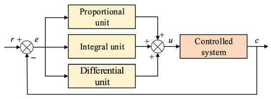
Figure 22.
Operational principle of PID control strategy.
To enhance the PID control performance, advanced optimization algorithms have been employed for tuning PID parameters, such as surrogate model-based algorithms [215,216,217], multi-objective evolutionary algorithms [218,219,220], and heuristic and meta-heuristic algorithms [221,222,223]. However, these methods are exclusively applicable for offline updates and cannot dynamically adjust PID parameters according to real-time driving conditions during vehicle operation, exhibiting inherent limitations. Wei et al. [224] designed a fuzzy PID controller for LMEERS, which employed a fuzzy control principle to adjust PID parameters online, thereby further improving control effectiveness. This strategy effectively rejects external disturbances and handles system uncertainties, particularly applicable for complex nonlinear systems like LMEERS. Furthermore, Ahmed et al. [225] recognized that the fuzzy rules in fuzzy PID controllers constitute an offline-constructed knowledge base, resulting in poor adaptability to varying road conditions. To address this limitation, the online modified Differential Evolution (DE) optimization algorithm-based Fuzzy-DE-PID control strategy was proposed, which reduced the control system’s dependency on offline fuzzy knowledge base. Li et al. [226] tackled issues of inaccurate parameter tuning and performance deterioration of traditional PID control for complex nonlinear systems by introducing a novel Fractional-Order PID (FOPID) control strategy. This approach combined the fractional-order theory with conventional PID control, expanding the actuator’s control bandwidth, thereby outperforming fuzzy PID in enhancing vehicle ride comfort.
5.2. Modern Control Methods
Classical control theory offers straightforward control laws and easy implementation, yet its limited control performance struggles to reconcile conflicting requirements in vehicle dynamic performances. Modern control methods, founded on state-space equations, represent an advanced extension of classical control theory. They typically focus on the evolution law of state variables in multi-input multi-output (MIMO) control systems [227,228]. For LMEERS, common modern control methods primarily include adaptive control, optimal control, and robust control.
5.2.1. Adaptive Control
Initially developed for aerospace control challenges, adaptive control maintains desired system performance amidst model uncertainties or external disturbances, with online adjustment to control parameters [229,230]. Vehicles in operation constitute stochastically varying nonlinear systems, making them well-suited for adaptive control applications [231]. Cai et al. [232] designed an energy regenerative adaptive controller enabling LMEERS to simultaneously achieve energy regeneration and active vibration suppression. The controller could attain regeneration efficiency of 35%, and improved vibration attenuation by 27% compared to viscous damping systems. Basaran et al. [233] proposed a Lyapunov-based adaptive backstepping control strategy, as illustrated in Figure 23, wherein the adaptive term estimated motor parameters to compute the desired drive current for LMEERS motors. This method effectively reduced the vertical displacement and pitch angle of the sprung mass, and the adaptive parameter estimation process exhibited rapid convergence.
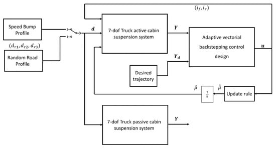
Figure 23.
Block diagram of the adaptive backstepping control strategy.
To mitigate the impact of linear motor nonlinearities on LMEERS active control performance, Li et al. [234] introduced adaptive control to compensate for response errors in the ideal motor drive current. The system dynamic responses at low frequencies were significantly improved compared to uncompensated control, thereby enhancing vehicle ride comfort. Gu et al. [235] developed a model-free adaptive sliding mode controller to mitigate the effects of modeling inaccuracies and time-varying parameters on LMEERS control performance. On the basis of the pseudo-gradient concept, the complex, hard-to-model dynamic model of LMEERS was transformed into a full-form dynamic linearized data model, thereby reducing the top-layer controller’s dependence on precise LMEERS modeling.
The core objective of adaptive control is to achieve online identification and compensation for system time-varying parameters, nonlinear dynamics, and external disturbances through real-time adjustments to controller parameters or structures. It is frequently embedded within other control theory frameworks, thereby forming composite control structures (e.g., adaptive robust control, adaptive sliding mode control), to enhance system robustness and tracking performance under unknown disturbances and model mismatches.
5.2.2. Optimal Control
The Linear Quadratic Regulator (LQR) represents the most mature and widely applied control strategy within optimal control [236]. Its principle involves constructing system state-space equations, defining control objectives, optimizing weighting coefficients, and applying control theory to derive the optimal control law under the defined control objectives. Skyhook control can be regarded as a special case of optimal control, alternatively termed suboptimal control.
Wu et al. [237] compared the vehicle body vibration isolation performance of the LQR and H∞ control strategies for linear motor-based electromagnetic active suspensions, with results demonstrating the superiority of LQR. Chen et al. [238] designed a hierarchical control strategy for electromagnetic active suspension, wherein LQR served as the top-layer controller to compute the optimal active force, and a GA was employed to optimize the LQR weighting coefficients. Wu et al. [239] investigated the dynamic behavior of a full-vehicle LMEERS system with LQR control under extreme operating conditions, as illustrated in Figure 24. The co-simulation results verified that LQR control significantly enhanced vehicle handling stability and driving safety.
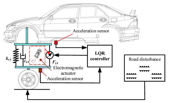
Figure 24.
System model of LQR control in Ref. [239].
Considering its multi-input nature in enabling more effective balance between ride comfort and driving safety, Lu et al. [240] adopted LQR control as the top-layer strategy for LMEERS in its active control mode, thereby achieving a 22.5% reduction in vehicle body acceleration compared to energy regeneration mode. To reduce motor energy consumption during LMEERS active control, Sun et al. [241] designed a modified LQR controller incorporating an energy consumption constraint into the traditional LQR weighting coefficient optimization model. In comparison with conventional LQR, this modified LQR reduced motor power by 80%, thereby effectively mitigating motor energy consumption and temperature rise issues, while still outperforming passive suspensions in dynamic performance. Azmi et al. [149] augmented the LQR optimal control law with a weighting factor of the suspension relative velocity, guiding the LMEERS operating point towards the high-efficiency regeneration zone, which enabled an additional 31% energy recovery. Bazios et al. [242] incorporated three performance indexes, namely vehicle body acceleration, dynamic tire load, and regeneration power, into the LQR objective function and investigated the influence of their weighting coefficients on LMEERS ride comfort, handling stability, and energy regeneration capability across varying excitation frequencies.
The above research collectively indicates that by modifying the LQR control model or selecting LQR as the controller for active mode, the conflicting demands of active vibration suppression and passive energy regeneration for LMEERS can be effectively reconciled.
5.2.3. Robust Control
Robust control primarily addresses uncertainties in suspension systems, such as parameter variations and unmodeled dynamics [243,244], with its main implementation approaches including H∞ control and Sliding Mode Control (SMC). The former enhances system robustness by minimizing the infinity norm of the closed-loop transfer function to reduce system sensitivity to various disturbances. Conversely, SMC delivers high robustness without requiring system identification during controller design, but it inherently suffers from chattering phenomena [245,246].
Hu et al. [247] designed a constrained H2/H∞ robust controller for linear motor-based electromagnetic active suspension, compensating for the motor’s output force to align actual suspension control force with the ideal target, thereby eliminating the impact of motor nonlinearities on suspension performance. Wu et al. [248] developed an H∞ robust controller based on Lyapunov stability theory to mitigate adverse effects of parameter uncertainties, actuator faults, and electromagnetic interference on LMEERS. Sande et al. [249] incorporated frequency-dependent weighting filters into the H∞ robust controller to balance ride comfort and handling stability in linear motor-based electromagnetic suspensions. Under convex pavement conditions, the active suspension achieved a 53% improvement in ride comfort over the passive suspension. To address the negative impact of actuator motion inertia and suspension structural nonlinearities on LMEERS control stability, Chen et al. [250] designed an H∞ robust controller and explicitly accounted for sensor noise effects on controller working performance. This strategy enhanced robust stability across diverse driving conditions.
Xie et al. [251] employed an integral SMC to suppress vertical vibration of the sprung mass in electromagnetic active suspensions, as illustrated in Figure 25, showing superior anti-disturbance performance compared to state feedback control. Zhang et al. [252] devised a model-independent SMC to improve robustness in electromagnetic active suspensions, featuring low computational complexity for reduced system latency. Li et al. [148] proposed an adaptive SMC to eliminate sprung mass variation effects and incorporated convergence-guaranteed constraints in the SMC design. Furthermore, performing online parameter optimization according to the real-time road surface information identification, ultimately the efficient coordination between LMEERS dynamic performances and energy regeneration capability was achieved.
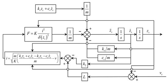
Figure 25.
Block diagram of the integral SMC strategy.
5.3. Intelligent Control Methods
Modern control methods struggle to achieve automatic parameter adjustment through self-organization or self-learning, limiting LMEERS performance under complex driving conditions. Intelligent control methods construct control strategies in imprecise ways by employing expert knowledge and empirical rules [253]. Representative intelligent control approaches primarily include fuzzy control, neural network control, and hybrid variants combining these with other algorithms.
5.3.1. Fuzzy Control
Fuzzy control comprises four core components: a fuzzification interface, a knowledge base, an inference machine, and a defuzzification interface [254,255]. Its operational principle is illustrated in Figure 26. This strategy exhibits strong robustness, as it does not rely on precise mathematical models of the controlled system, making it applicable for addressing the nonlinearities, strong couplings, and time-varying characteristics inherent in control processes, and demonstrating considerable fault tolerance [256]. However, the construction of the knowledge base is inherently subjective, and the fuzzification processing of information will lead to reduced control precision and deteriorated dynamic performance [257].
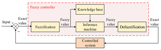
Figure 26.
Operational principle of fuzzy control strategy.
Kou et al. [258] designed an endocrine feedback-based fuzzy control strategy for LMEERS, demonstrating enhanced dynamic performance over conventional fuzzy control. Wei et al. [224] utilized fuzzy control to optimize PID parameters online, significantly improving ride comfort under random and impulse road excitations for linear motor-based electromagnetic suspensions. Min et al. [259] employed fuzzy control to identify bounded disturbances and unknown steady-state parameters in the nonlinear electromagnetic active suspension system. Liu et al. [200] proposed a PD control strategy based on the variable universe fuzzy theory, enabling EERS to recover over 18% of vibration energy and simultaneously optimizing ride comfort and handling stability. Fuzzy control was introduced by Deng et al. [260] to eliminate chattering in SMC, and a fuzzy sliding mode variable structure control strategy was developed. Subsequently, the multi-mode switching control scheme for electro-hydraulic composite LMEERS was designed, thereby concurrently improving the dynamic performances and energy regeneration capability of LMEERS. When designing the energy regeneration control strategy for an electro-hydraulic composite LMEERS, Yin [261] applied fuzzy control to the real-time voltage stabilization of the regeneration circuit, achieving a regeneration power of 70 W under C-class roads. Soudani et al. [262] proposed a novel three-input fuzzy logic controller that substantially reduced vehicle body acceleration compared to widely used two-input controllers, thereby enhancing ride comfort. Ren et al. [263] adopted T-S fuzzy theory to address uncertainties in active suspension systems, introducing a homogeneous polynomial parameter-dependent fuzzy controller that significantly increases the flexibility of fuzzy control.
5.3.2. Neural Network Control
Neural network control possesses nonlinear adaptive information processing capabilities, overcoming limitations of traditional artificial intelligence methods in handling intuitive tasks such as pattern identification, speech recognition, and unstructured information processing. This enables its successful application in fields such as neural expert systems, pattern identification, intelligent control, combinatorial optimization, and prediction [264,265]. However, as a black-box system, neural network control cannot explain its reasoning process or rationale, and it struggles to achieve effective control without sufficient training data [266].
Liu et al. [267] designed a BP neural network PID controller for EERS, wherein the BP neural network provided adaptive parameters for the PID control strategy. Compared with conventional PID, BP-PID demonstrated superior performance in enhancing both dynamic performance and energy regeneration capability. Notably, the regeneration efficiency of BP-PID remained nearly constant across varying road conditions, indicating the excellent adaptability and stability of the neural network control. Li et al. [148] employed an adaptive neural network algorithm to identify road surface levels, and then switched the optimal control parameters, thereby enabling balance between the vibration suppression and energy regeneration of LMEERS. Focusing on the critical engineering challenges in active suspension systems, including high consumption, input delay, and unknown/uncertain disturbances, Zhang et al. [268] proposed an adaptive neural network control method, wherein the neural network worked to estimate system disturbances. This hybrid strategy could facilitate online updates of input and output weights for neural networks and intentionally incorporate beneficial nonlinearities into vibration control. To resolve the issues of unmeasurable states and control input saturation constraints in active suspensions, Wang et al. [202] developed a state observation-based adaptive neural network output feedback control algorithm, ensuring robust vehicle dynamic performance.
Benefitting from strong nonlinear modeling capacity and multi-objective adaptability, neural network algorithms are frequently deployed as decision-makers for multi-mode switching control in suspension systems. Confronted with the difficulty of single-strategy control systems in simultaneously optimizing driving safety, ride comfort, and energy feedback of regenerative suspensions, Qu et al. [203] implemented adaptive switching of key top-layer controller parameters with a BP neural network, as illustrated in Figure 27.
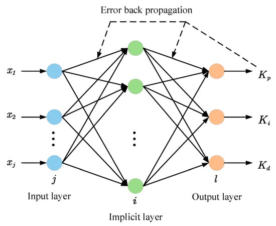
Figure 27.
BP neural network.
5.3.3. Hybrid Variants with Other Algorithms
Currently, combining classical and modern control methods represents the development trend of intelligent control methods, utilizing their self-learning capabilities to further enhance classical and modern controller performances. Li et al. [269] employed fuzzy logic theory to perform online estimation of the nonlinear dynamic model of the electromagnetic suspension actuator and unmeasurable suspension state variables. And then an adaptive fuzzy output feedback fault-tolerant control strategy was proposed, guaranteeing vertical dynamic performance even during actuator failures. Homayoun et al. [270] introduced a Radial Basis Function Neural Network (RBFNN)-based minimal learning backstepping control method to address the stochastic disturbances and actuator output saturation in nonlinear active suspension systems.
Intelligent optimization algorithms, such as GA and Particle Swarm Optimization (PSO), valued for their broad applicability, high robustness, and conceptual simplicity, are widely used to optimize control strategy parameters for maximizing control effectiveness or enabling multi-mode switching control [271,272,273]. Hu et al. [274] aimed at comprehensively improving ride comfort and handling stability, achieving optimal matching between suspension parameters and LQR controller via a multi-objective PSO algorithm. The optimized LQR significantly enhanced overall vehicle dynamic performances. Kou et al. [275] utilized the Gravitational Search Algorithm (GSA) to globally optimize the weighting coefficients of LQR controllers across three working modes of an electro-hydraulic composite LMEERS, thereby satisfying dynamic demands under varying driving conditions.
With the increasing computational power of on-vehicle chips and decreasing hardware costs, deep learning-based intelligent control methods are gradually becoming popular in vehicle suspension control. The high-dimensional fitting capability of intelligent algorithms can replace mathematical modeling, solving complex control problems through end-to-end learning [276]. Addressing the challenge of electromagnetic suspension systems adapting to vibration suppression demands in time-varying environments due to nonlinearities and uncertainties, Zhan et al. [201] modified a Deep Reinforcement Learning (DRL) network based on the actuator dynamic model, and then proposed a semi-active control strategy utilizing Neural Ordinary Differential Equations (NODEs) with the Proximal Policy Optimization (PPO) algorithm. Compared to fuzzy PID control, this hybrid strategy achieved superior vibration attenuation performance. Wang et al. [277] presented a DRL-based active suspension control algorithm, employing Deep Deterministic Policy Gradients (DDPGs) to significantly improve control performance, thereby yielding a faster response speed than the LQR controller.
In summary, the top-layer control methods critically influence the coordination between active control and energy regeneration of LMEERS, thereby directly impacting overall vehicle dynamic performance and energy economy. Different control strategies exhibit distinct advantages and limitations. A comparative analysis of the characteristics of control strategies commonly employed for LMEERS is provided in Table 7, serving as a technical reference for subsequent selection and design of control methods. The selection of a control strategy is a multifaceted decision that extends beyond mere performance indexes. While modern and intelligent control methods often provide superior theoretical performance, their practicability is a major concern. Strategies like LQR and adaptive control can be computationally intensive and require accurate system models, which are difficult to obtain for nonlinear suspension systems and may not be robust to parameter variations. Sliding mode control offers robustness but introduces undesirable chattering. Although intelligent methods, like fuzzy logic and neural network, handle nonlinearities well, they often suffer from a lack of transparency (“black-box” nature), significant calibration effort, and high computational load, posing challenges for deployment on low-cost automotive microcontrollers. In contrast, classical methods, like Skyhook and PID, while less optimal in complex scenarios, offer simplicity, ease of implementation, and proven reliability, explaining their continued prevalence in commercial applications.
Table 7.
Comparative analysis of the characteristics of control strategies for LMEERS.
Therefore, the evolution of LMEERS control methods is not just about pursuing algorithmic complexity but also about advancing computational hardware and developing simplified yet effective strategies that bridge the gap between performance and practicality.
6. Current Challenges and Development Trends in LMEERS
6.1. Current Principal Challenges
Integrating dual functionalities of active control and energy regeneration, LMEERS performs better alignment with automotive demands of dynamic performance and energy efficiency, representing a pivotal structural configuration for next-generation high-performance suspension systems. However, several persistent technical challenges impede their commercialization, necessitating solutions in future research.
- 1.
- Conflict between energy recovery efficiency and net energy-saving effectiveness:
On one hand, LMEERS faces intrinsic energy regeneration efficiency limitations. Under specific conditions, such as low-frequency, small-amplitude excitations of urban congestion, the linear motor yields insufficient regeneration voltage, resulting in poor energy recovery. On the other hand, energy losses occur throughout the regeneration pathway from LMEERS to storage systems, involving multi-stage conversions (rectification, voltage stabilization and storage), leading to low net regeneration rates. Furthermore, active suspension control algorithms with high energy consumption struggle to achieve net energy gain. Studies indicate that actual on-road recovered energy only accounts for a small part of the total suspension dissipated energy.
- 2.
- Engineering challenges in thrust density versus volume/weight:
LMEERS’s linear motor must simultaneously deliver long stroke and high thrust, inevitably increasing the volume and weight of suspension actuators. Conventional cylindrical PMSMs offer limited thrust density, failing to meet requirements for ample thrust within compact structures. Consequently, developing novel high-performance motor topologies is imperative. Additionally, liquid-cooling systems implemented to manage motor thermal loads further escalate structural complexity and mass. Excessive motor weight drastically increases unsprung mass, consequently deteriorating suspension dynamic performance.
- 3.
- Limitations in control algorithm hysteresis and complexity:
On one hand, high-frequency road excitation induces severe fluctuations in LMEERS feedback signals, necessitating dynamic motor load adjustments for stable force output. However, existing control strategies exhibit response hysteresis and control overshoot, hindering precise attainment of desired control objectives. On the other hand, intelligent algorithms (top-layer control coupled with road surface identification) capable of concurrently optimizing ride comfort, driving safety, and energy regeneration capability entail substantial online computational resources. This elevates hardware requirements for sensors and control chips on conventional vehicles, increasing manufacturing costs and control risks.
6.2. Future Development Trends
The commercialization of LMEERS hinges on overcoming the challenges detailed in Section 6.1, which are not of equal priority but exist in a hierarchical relationship. Among them, the primary and fundamental challenge is the inherent trade-off between energy recovery efficiency and vehicle dynamic performance (Challenge #1). This is the core dilemma that defines the LMEERS system and is the ultimate problem that all other research must solve. The goal is not to maximize one at the complete expense of the other but to develop strategies for intelligent trade-off management. The key enabling challenge is the thrust density versus volume/weight constraint of the linear motor (Challenge #2). This is a primary technological bottleneck because a bulky, low-efficiency actuator directly undermines both the dynamic performance (by increasing unsprung mass) and the energy-saving capability (by lowering regeneration power). Advancements here are prerequisites for achieving a viable system capable of effectively implementing any high-level control strategy. The critical implementation challenge is the computational complexity and hysteresis of advanced control algorithms (Challenge #3). This challenge becomes paramount once the hardware is capable. The most effective control strategy is irrelevant if it cannot be reliably executed in real time on affordable automotive hardware. Research must focus not only on algorithmic performance but also on their computational efficiency and robustness.
Therefore, future development trends should be prioritized to address these challenges in a logical sequence: firstly, by developing high-performance actuators to alleviate hardware limitations; secondly, by creating intelligent and computationally efficient algorithms to manage the fundamental performance–energy trade-off; and finally, by integrating these solutions into a robust and scalable system. The following trends are discussed within this prioritized framework.
- 1.
- Optimal design of motor topology and peripheral circuits:
Optimize the primary and secondary structural design and dimensional parameters, employing high-performance magnetic materials and Halbach arrays to enhance magnetic field unidirectionality, thereby increasing air-gap flux density. This approach will comprehensively improve the motor’s damping, thrust, and regenerative characteristics. Meanwhile, reduce the volume and weight of motors to achieve lightweighting objectives. In addition, design safe and efficient regeneration–storage systems and optimize energy recovery hardware circuits and control algorithms to enhance regeneration responsiveness, thereby elevating net energy recovery efficiency.
- 2.
- Application of high-voltage platforms and advanced thermal management:
Adopt high-voltage driving configurations to reduce copper losses in linear motor windings and to increase thrust density, ensuring the compatibility with electrical architectures of new energy vehicles. Realizing high-voltage operation in LMEERS necessitates breakthroughs in some key technologies, such as primary winding, insulation materials, and power electronics. Integrate motor cooling within the vehicle thermal management system, optimizing cooling channel topology and applying novel thermal interface materials. Synergistically combine thermal management control with suspension control to implement predictive cooling.
- 3.
- Enhancing the energy efficiency ratio via composite configurations:
Integrate hydraulic, electro, and inerter components with linear motors to ensure that LMEERS maintains dynamic characteristics during energy regeneration and fail-safe properties during active control. Furthermore, develop tailored control schemes according to the performance advantages of various composite configurations to improve comprehensive suspension performance. Among these configurations, the electro-hydraulic composite types, which offer easy implementation, high reliability, and sufficient hard damping, will dominate mainstream solutions, yet their lightweighting and integration remain a critical research focus.
- 4.
- Intelligent control and vehicle-road coordination:
Enable LMEERS with multiple working modes (e.g., comfort, sport, and economy modes) to balance active control and energy recovery across diverse driving scenarios. Utilize road surface information as the multi-mode switching criterion, and integrate intelligent control methods into suspension top-layer controller to enhance the road adaptability of LMEERS. Realize automatic adjustment to control parameters and adaptive switching of working modes, further elevating overall vehicle performance. Additionally, stability control during mode switching also requires focused attention.
7. Conclusions
Automotive energy-saving technologies have garnered extensive global research attention. As the critical subsystem, the suspension system’s performance in vibration attenuation and energy recovery directly influence vehicle dynamic performance and energy efficiency. Its configuration design stands as a key factor constraining its properties. Linear motor electromagnetic energy regenerative suspension (LMEERS), which integrates dual functionalities of active control and energy regeneration, demonstrates significant potential to overcome the performance limitations of conventional suspension architectures. It represents a pivotal development direction for next-generation high-performance suspension systems. Therefore, this review comprehensively synthesizes the state-of-the-art of the key technologies of LMEERS across four dimensions: configuration design, performance optimization, functionality switching criterion identification, and top-layer control strategies. To succinctly encapsulate the core insights of this review, the main findings across the four primary technological domains are summarized in Table 8.
Table 8.
Summary of main findings of key technologies for LMEERS.
- In terms of configuration design, the cylindrical PMSM is typically employed as the system actuator. To further enhance system reliability and overcome the limitations of a single-motor structure in damping characteristics and fault-safe performance, LMEERS is commonly integrated with auxiliary devices, primarily forming three composite configurations: electro-hydraulic, electro-electro, and electro-inerter types. Among these, the electro-hydraulic type is considered the most promising for engineering applications owing to its simple structure, high reliability, and ability to provide inherent hard damping.
- Regarding performance optimization, efforts focus on damping, thermal, thrust, and regenerative characteristics, which are enhanced through structural refinement, parametric optimization, and intelligent control. Currently, damping characteristics is typically enhanced by integrating the eddy current or hydraulic damping modules. Parametric optimization and implementing cooling systems are simple and effective approaches to mitigate motor temperature rise. Thrust and regenerative characteristics, being critical to the functional behavior of LMEERS, require a comprehensive set of approaches for improvement. Additionally, emerging optimization methods, such as DT and AI, demonstrate substantial application potential.
- In the aspect of functionality switching criterion identification, road information (including road roughness and road type) serves as the key criterion for coordinating the dual-functionality switching of LMEERS. Two on-vehicle approaches, namely image-based methods and dynamic response-based methods, have been developed and compared. The former offers preemptive perception of the road ahead and high identification accuracy, but it suffers from high equipment costs and poor environmental adaptability. In contrast, the latter provides superior robustness and cost advantages, yet struggles to identify complex road surfaces. Therefore, multi-sensor fusion-based road information identification methods, capitalizing on the advantages of both methods, represent a future direction for on-vehicle solutions.
- Concerning top-layer control strategies, classical control (e.g., skyhook control, PID), modern control (e.g., adaptive control, LQR, robust control), and intelligent control (e.g., fuzzy control, neural network control) methods are widely applied and increasingly integrated. The introduction of intelligent optimization algorithms (e.g., PSO, GA) and deep learning methods has further improved the adaptive capability and multi-objective coordination performance of control systems.
Nonetheless, LMEERS still faces challenges, such as unsatisfactory net energy saving effectiveness, limited feasibility in engineering application, and limitations in control algorithm hysteresis and complexity. Future development of LMEERS will trend towards integration, lightweighting, standardization, intellectualization, and multi-modal operation. Specific development directions include the following:
- Optimize motor topology and peripheral circuit design to enhance magnetic field orientation and energy recovery responsiveness.
- Apply high-voltage platforms and advanced thermal management technologies for compatibility with electrical architectures in new energy vehicles.
- Develop composite configurations and cooperative control strategies to improve overall system energy efficiency ratio and reliability.
- Integrate vehicle–road coordination with intelligent decision-making to achieve adaptive switching between multiple operational modes for global performance optimization.
Author Contributions
Conceptualization, D.S.; methodology, D.S. and R.D. (Renkai Ding); validation, R.D. (Renkai Ding); writing—original draft preparation, D.S.; writing—review and editing, R.D. (Rijing Dong). All authors have read and agreed to the published version of the manuscript.
Funding
This research was funded by the National Key Research and Development Program of China (2023YFB2504500), the National Natural Science Foundation Project of China (52472410), and the Project of College of Agricultural Engineering, Jiangsu University (NZXB20210101).
Data Availability Statement
Not applicable.
Conflicts of Interest
Author Rijing Dong was employed by the company CSSC Power (Group) Co., Ltd. The remaining authors declare that the research was conducted in the absence of any commercial or financial relationships that could be construed as a potential conflict of interest.
References
- Zhu, Z.; Yang, Y.P.; Wang, D.Q.; Cai, Y.F.; Lai, L.H. Energy Saving Performance of Agricultural Tractor Equipped with Mechanic-Electronic-Hydraulic Powertrain System. Agriculture 2022, 12, 436. [Google Scholar] [CrossRef]
- Zhu, Z.H.; Chai, X.Y.; Xu, L.Z.; Quan, L.; Yuan, C.C.; Tian, S.C. Design and performance of a distributed electric drive system for a series hybrid electric combine harvester. Biosyst. Eng. 2023, 236, 160–174. [Google Scholar] [CrossRef]
- Zhu, Z.; Zeng, L.X.; Chen, L.; Zou, R.; Cai, Y.F. Fuzzy Adaptive Energy Management Strategy for a Hybrid Agricultural Tractor Equipped with HMCVT. Agriculture 2022, 12, 1986. [Google Scholar] [CrossRef]
- Liu, J.; Xia, C.G.; Jiang, D.L.; Shang, G.G.; Han, J.Y.; Sun, Y. Determination and Application of Maximum Efficiency Curve of Crawler Electric Tractor Motors. Math. Probl. Eng. 2021, 2021, 1310926. [Google Scholar] [CrossRef]
- Heydari, S.; Fajri, P.; Rasheduzzaman, M.; Sabzehgar, R. Maximizing Regenerative Braking Energy Recovery of Electric Vehicles Through Dynamic Low-Speed Cutoff Point Detection. IEEE Trans. Transp. Electrif. 2019, 5, 262–270. [Google Scholar] [CrossRef]
- Park, Y.; Park, S.; Ahn, C. Performance Potential of Regenerative Braking Energy Recovery of Autonomous Electric Vehicles. Int. J. Control Autom. Syst. 2023, 21, 1442–1454. [Google Scholar] [CrossRef]
- Cui, L.F.; Mao, H.P.; Xue, X.Y.; Ding, S.M.; Qiao, B.Y. Optimized design and test for a pendulum suspension of the crop spray boom in dynamic conditions based on a six DOF motion simulator. Int. J. Agric. Biol. Eng. 2018, 11, 76–85. [Google Scholar] [CrossRef]
- Ding, R.K.; Wang, R.C.; Meng, X.P.; Chen, L. Mode-switching control and stability analysis of a hybrid electromagnetic actuator for the vehicle suspension. J. Vib. Control 2020, 26, 1804–1814. [Google Scholar] [CrossRef]
- Niu, H.Z.; Zhang, N.; Lu, Y.; Zhang, Z.; Li, M.N.; Liu, J.X.; Zhang, N.; Song, W.Q.; Zhao, Y.Z.; Miao, Z.C. Strategies toward the development of high-energy-density lithium batteries. J. Energy Storage 2024, 88, 111666. [Google Scholar] [CrossRef]
- Zou, X.Y.; Ma, C.W.; Xu, T.; Li, R.L.; Wang, H.X.; Chen, F. Evolution mechanism and response strategy of interface mechanics in all solid-state lithium metal batteries. J. Energy Storage 2023, 74, 109483. [Google Scholar] [CrossRef]
- Xu, L.Z.; Chai, X.Y.; Gao, Z.P.; Li, Y.M.; Wang, Y.D. Experimental study on driver seat vibration characteristics of crawler-type combine harvester. Int. J. Agric. Biol. Eng. 2019, 12, 90–97. [Google Scholar] [CrossRef]
- Yao, W.M. Suspension System. In Automobile Structure, 7th ed.; China Communications Press: Beijing, China, 2021; Volume 2, pp. 456–478. ISBN 978-7-1141-7116-1. [Google Scholar]
- Chen, Y.X.; Chen, L.; Wang, R.C.; Xu, X.; Shen, Y.J.; Liu, Y.L. Modeling and test on height adjustment system of electrically-controlled air suspension for agricultural vehicles. Int. J. Agric. Biol. Eng. 2016, 9, 40–47. [Google Scholar] [CrossRef]
- Cui, L.F.; Xue, X.Y.; Le, F.X.; Mao, H.P.; Ding, S.M. Design and experiment of electro hydraulic active suspension for controlling the rolling motion of spray boom. Int. J. Agric. Biol. Eng. 2019, 12, 72–81. [Google Scholar] [CrossRef]
- Wang, H.; Jasim, A.; Chen, X.D. Energy harvesting technologies in roadway and bridge for different applications—A comprehensive review. Appl. Energy 2018, 212, 1083–1094. [Google Scholar] [CrossRef]
- Fu, C.Z.; Lu, J.Y.; Ge, W.Q.; Tan, C.; Li, B. A review of electromagnetic energy regenerative suspension system & key technologies. Comput. Model. Eng. Sci. 2023, 135, 1779–1824. [Google Scholar] [CrossRef]
- Ebrahimi, B.; Bolandhemmat, H.; Khamesee, M.B.; Golnaraghi, F. A hybrid electromagnetic shock absorber for active vehicle suspension systems. Veh. Syst. Dyn. 2011, 49, 311–332. [Google Scholar] [CrossRef]
- Chen, Z.S.; Cao, J.Y.; Qin, Z.Y.; Chen, Z.W.; Xiong, Y.P. Simultaneous Vibration Suppression and Energy Harvesting of Vehicle Suspension Systems: Status and Prospects. J. Mech. Eng. 2022, 58, 3–26. [Google Scholar] [CrossRef]
- Li, Y.; Misra, M.; Gregori, S. Comparison of conventional and regenerative electrostatic energy harvesters. IET Circ. Devices Syst. 2017, 11, 638–647. [Google Scholar] [CrossRef]
- Wu, Y.F.; Zou, J.W.; Tang, K.; Xia, Y.; Wang, X.X.; Song, L.L.; Wang, J.H.; Wang, K.; Wang, Z.H. From electricity to vitality: The emerging use of piezoelectric materials in tissue regeneration. Burn. Trauma 2024, 12, tkae013. [Google Scholar] [CrossRef] [PubMed]
- Conta, G.; Libanori, A.; Tat, T.; Chen, G.R.; Chen, J. Triboelectric Nanogenerators for Therapeutic Electrical Stimulation. Adv. Mater. 2021, 33, 2007502. [Google Scholar] [CrossRef]
- Zhang, B.F.; Zhao, Z.; Li, Y.X.; Zhang, X.H.; Li, X.J.; Hao, D.N.; Zhang, Z.T. Design and analysis of a piezoelectric energy harvesting shock absorber for light truck applications. Appl. Energy 2025, 377, 124569. [Google Scholar] [CrossRef]
- Yan, J.H.; Li, B.; Shi, Y.; Zhang, L.Y.; Heng, P.R. Multi-objective stratified optimization design of tubular permanent magnet linear motors with nonuniform teeth for active suspension. Acta Armamentarii 2023, 32, 40–50. [Google Scholar] [CrossRef]
- Zou, J.Y.; Guo, X.X.; Abdelkareem, M.A.A.; Xu, L.; Zhang, J. Modelling and ride analysis of a hydraulic interconnected suspension based on the hydraulic energy regenerative shock absorbers. Mech. Syst. Signal Process. 2019, 127, 345–369. [Google Scholar] [CrossRef]
- Demirkol, Z.; Hasirci, U.; Demirci, R. Design, Implementation and Test of a Novel Cylindrical Permanent Magnet DC Linear Motor. Energies 2023, 16, 3491. [Google Scholar] [CrossRef]
- Sun, G.P.; Zhao, M.; Li, J.J.; Yao, T.; Zhang, H.Q. Design and Analysis of Tubular Transverse Flux Permanent Magnet Linear Motor. Energies 2024, 17, 6180. [Google Scholar] [CrossRef]
- Liu, X.; Gao, J.; Huang, S.D.; Lu, K.Y. Magnetic Field and Thrust Analysis of the U-Channel Air-Core Permanent Magnet Linear Synchronous Motor. IEEE Trans. Magn. 2017, 53, 8201504. [Google Scholar] [CrossRef]
- Zhang, X.Y.; Wang, Z.Q.; Liu, T. Anti-Disturbance Integrated Position Synchronous Control of a Dual Permanent Magnet Synchronous Motor System. Energies 2022, 15, 6697. [Google Scholar] [CrossRef]
- Tabassum, A.A.; Cho, H.M.; Mahmud, M.I. Essential Features and Torque Minimization Techniques for Brushless Direct Current Motor Controllers in Electric Vehicles. Energies 2024, 17, 4562. [Google Scholar] [CrossRef]
- Xu, Z.Y.; Li, T.; Zhang, F.G.; Zhang, Y.; Lee, D.H.; Ahn, J.W. A Review on Segmented Switched Reluctance Motors. Energies 2022, 15, 9212. [Google Scholar] [CrossRef]
- Jin, Y.C.; Liu, J.Z.; Xu, Z.J.; Yuan, S.Q.; Li, P.P.; Wang, J.Z. Development status and trend of agricultural robot technology. Int. J. Agric. Biol. Eng. 2021, 14, 1–19. [Google Scholar] [CrossRef]
- Yang, S.; Zhai, C.Y.; Gao, Y.Y.; Dou, H.J.; Zhao, X.G.; He, Y.K.; Wang, X. Planting uniformity performance of motor-driven maize precision seeding systems. Int. J. Agric. Biol. Eng. 2022, 15, 101–108. [Google Scholar] [CrossRef]
- Gysen, B.L.J.; Janssen, J.L.G.; Paulides, J.J.H.; Lomonova, E.A. Design Aspects of an Active Electromagnetic Suspension System for Automotive Applications. IEEE Trans. Ind. Appl. 2009, 45, 1589–1597. [Google Scholar] [CrossRef]
- Wang, R.L.; Zhang, L.; Shi, C.Y.; Zhao, C.Q.; Yang, K. Analysis and Optimization of a Moving Magnet Permanent Magnet Synchronous Planar Motor with Split Halbach Arrays. Energies 2025, 18, 1388. [Google Scholar] [CrossRef]
- Sun, Z.L.; Jia, G.Y.; Huang, C.B.; Zhou, W.C.; Mao, Y.H.; Lei, Z.R. Accurate Modeling and Optimization of Electromagnetic Forces in an Ironless Halbach-Type Permanent Magnet Synchronous Linear Motor. Energies 2023, 16, 5785. [Google Scholar] [CrossRef]
- Li, H.F.; Cui, L.F.; Ma, Z.G.; Li, B. Multi-Objective Optimization of the Halbach Array Permanent Magnet Spherical Motor Based on Support Vector Machine. Energies 2020, 13, 5704. [Google Scholar] [CrossRef]
- Xu, C.; Wu, H.; Shi, Y.C.; Wang, N.; Song, L.W. Study on the Influences of an Outer-Coreless-Rotor Permanent Magnet Synchronous Machine Using Halbach Magnet Array. Energies 2024, 17, 3108. [Google Scholar] [CrossRef]
- Wang, R.C.; Ding, R.K.; Chen, L. Application of hybrid electromagnetic suspension in vibration energy regeneration and active control. J. Vib. Control 2018, 24, 223–233. [Google Scholar] [CrossRef]
- Ding, R.K.; Wang, R.C.; Meng, X.P.; Chen, L. Energy consumption sensitivity analysis and energy-reduction control of hybrid electromagnetic active suspension. Mech. Syst. Signal Process. 2019, 134, 106301. [Google Scholar] [CrossRef]
- Ding, R.K.; Wang, R.C.; Meng, X.P.; Chen, L. Study on coordinated control of the energy regeneration and the vibration isolation in a hybrid electromagnetic suspension. Proc. Inst. Mech. Eng. Part D-J. Automob. Eng. 2017, 231, 1530–1539. [Google Scholar] [CrossRef]
- Ding, R.K.; Wang, R.C.; Meng, X.P. Energy-saving control strategy design and structure realization for electromagnetic active suspension. Proc. Inst. Mech. Eng. Part C-J. Eng. Mech. Eng. Sci. 2019, 233, 3060–3075. [Google Scholar] [CrossRef]
- Wei, W.; Yu, S.J.; Li, B.Z. Research on Magnetic Characteristics and Fuzzy PID Control of Electromagnetic Suspension. Actuators 2023, 12, 203. [Google Scholar] [CrossRef]
- Kou, F.R.; Li, M.X.; He, J.J.; Xu, J.N.; Wu, J.H. Layered coordinated control of self-powered electromagnetic hybrid suspension based on energy analysis. J. Vib. Shock 2023, 42, 98–108. [Google Scholar] [CrossRef]
- Kou, F.R.; He, J.J.; Li, M.X.; Xu, J.N.; Wu, D.P. Adaptive fuzzy control of an electromagnetic hybrid suspension based on road recognition. J. Vib. Shock 2023, 42, 303–311. [Google Scholar] [CrossRef]
- Chen, C.; Liao, W.H. A self-sensing magnetorheological damper with power generation. Smart Mater. Struct. 2012, 21, 025014. [Google Scholar] [CrossRef]
- Wang, R.C.; Jiang, Y.; Ding, R.K.; Liu, W.; Meng, X.P.; Sun, Z.Y. Design and experimental verification of self-powered electromagnetic vibration suppression and absorption system for in-wheel motor electric vehicles. J. Vib. Control 2022, 28, 2544–2555. [Google Scholar] [CrossRef]
- Zhang, X.Y.; Chen, R.W.; Ren, L.; Ren, S.M.; Wang, L.P. Design and test of hybrid electromagnetic regenerative suspension damper. Chin. J. Sci. Instrum. 2019, 40, 132–139. [Google Scholar] [CrossRef]
- Hu, Y.Q.; Wang, X.L.; Qin, Y.C.; Li, Z.H.; Wang, C.F.; Wu, H. A robust hybrid generator for harvesting vehicle suspension vibration energy from random road excitation. Appl. Energy 2022, 309, 118506. [Google Scholar] [CrossRef]
- Suda, Y.; Nakadai, S.; Nakano, K. Hybrid suspension system with skyhook control and energy regeneration (development of self-powered active suspension). Veh. Syst. Dyn. 1998, 29, 619–634. [Google Scholar] [CrossRef]
- Li, C.C.; Zhou, C.Y.; Xiong, J.Y. New Method to Coordinate Vibration Energy Regeneration and Dynamic Performance of In-Wheel Motor Electrical Vehicles. Energies 2023, 16, 2968. [Google Scholar] [CrossRef]
- Wang, R.C.; Liu, W.; Cai, Y.F.; Chen, L. Hybrid-Electromagnetic Suspension Capable of Self-Powering and Control Method Thereof. U.S. Patent 12,054,023, 6 August 2024. [Google Scholar]
- Yang, X.F.; Zhang, T.Y.; Shen, Y.J.; Liu, Y.L.; Bui, V.; Qiu, D.D. Tradeoff analysis of the energy-harvesting vehicle suspension system employing inerter element. Energy 2024, 308, 132841. [Google Scholar] [CrossRef]
- Shen, Y.J.; Shi, D.H.; Chen, L.; Liu, Y.L.; Yang, X.F. Modeling and experimental tests of hydraulic electric inerter. Sci. China-Technol. Sci. 2019, 62, 2161–2169. [Google Scholar] [CrossRef]
- Shen, Y.J.; Liu, Y.L.; Chen, L.; Yang, X.F. Optimal design and experimental research of vehicle suspension based on a hydraulic electric inerter. Mechatronics 2019, 61, 12–19. [Google Scholar] [CrossRef]
- Hu, J.B. Nonlinear Evolution and Predictive Control of Vehicle Hydro-electric Coupling ISD Suspension. Master’s Thesis, Jiangsu University, Zhenjiang, China, 2018. [Google Scholar]
- He, L.D.; Liu, Y.Z.; Han, S.L. Comparative Study between Two Schemes of Active-Control-Based Mechatronic Inerter. In Proceedings of the 3rd International Conference on Mechatronics and Mechanical Engineering (ICMME), Shanghai, China, 21–23 October 2016; pp. 1–8. [Google Scholar] [CrossRef]
- Gonzalez-Buelga, A.; Clare, L.R.; Neild, S.A.; Jiang, J.Z.; Inman, D.J. An electromagnetic inerter-based vibration suppression device. Smart Mater. Struct. 2015, 24, 055015. [Google Scholar] [CrossRef]
- Rakshith, M.; Kumar, Y.; Vikas, S.G. Bose automotive suspension. Int. J. Recent Technol. Eng. 2014, 3, 13–18. [Google Scholar]
- Fang, Y.J. In-depth Analysis of BYD’s DiSus-Z Electromagnetic Suspension Technology. Auto Maint. Repair 2024, 11, 71–73. [Google Scholar] [CrossRef]
- Lee, S.; Kim, W.J. Active Suspension Control With Direct-Drive Tubular Linear Brushless Permanent-Magnet Motor. IEEE Trans. Control Syst. Technol. 2010, 18, 859–870. [Google Scholar] [CrossRef]
- Wang, J.B.; Wang, W.Y.; Atallah, K. A Linear Permanent-Magnet Motor for Active Vehicle Suspension. IEEE Trans. Veh. Technol. 2011, 60, 55–63. [Google Scholar] [CrossRef]
- Tang, N.Q.; Sun, J.; Yao, K.S.; Zhou, X.; Tian, Y.; Cao, Y.; Nirere, A. Identification of Lycium barbarum varieties based on hyperspectral imaging technique and competitive adaptive reweighted sampling-whale optimization algorithm-support vector machine. J. Food Process Eng. 2021, 44, e13603. [Google Scholar] [CrossRef]
- Zhang, H.W.; Ji, W.; Xu, B.; Yu, X.W. Optimizing Contact Force on an Apple Picking Robot End-Effector. Agriculture 2024, 14, 996. [Google Scholar] [CrossRef]
- Yang, H.T.; Sun, Y.; Xia, C.G.; Zhang, H.D. Research on Energy Management Strategy of Fuel Cell Electric Tractor Based on Multi-Algorithm Fusion and Optimization. Energies 2022, 15, 6389. [Google Scholar] [CrossRef]
- Tang, X.D.; Lin, T.; Zuo, L. Design and Optimization of a Tubular Linear Electromagnetic Vibration Energy Harvester. IEEE-ASME Trans. Mechatron. 2014, 19, 615–622. [Google Scholar] [CrossRef]
- Gysen, B.L.J.; van der Sande, T.P.J.; Paulides, J.J.H.; Lomonova, E.A. Efficiency of a Regenerative Direct-Drive Electromagnetic Active Suspension. IEEE Trans. Veh. Technol. 2011, 60, 1384–1393. [Google Scholar] [CrossRef]
- Gysen, B.L.J.; Paulides, J.J.H.; Janssen, J.L.G.; Lomonova, E.A. Active Electromagnetic Suspension System for Improved Vehicle Dynamics. IEEE Trans. Veh. Technol. 2010, 59, 1156–1163. [Google Scholar] [CrossRef]
- Tang, X.D.; Liu, Y.L.; Cui, W.; Zuo, L. Analytical Solutions to H2 and H∞ Optimizations of Resonant Shunted Electromagnetic Tuned Mass Damper and Vibration Energy Harvester. J. Vib. Acoust.-Trans. ASME 2016, 138, 011018. [Google Scholar] [CrossRef]
- Asadi, E.; Ribeiro, R.; Khamesee, M.B.; Khajepour, A. A new adaptive hybrid electromagnetic damper: Modelling, optimization, and experiment. Smart Mater. Struct. 2015, 24, 075003. [Google Scholar] [CrossRef]
- Asadi, E.; Ribeiro, R.; Khamesee, M.B.; Khajepour, A. Analysis, Prototyping, and Experimental Characterization of an Adaptive Hybrid Electromagnetic Damper for Automotive Suspension Systems. IEEE Trans. Veh. Technol. 2017, 66, 3703–3713. [Google Scholar] [CrossRef]
- Xu, J.A.; Kou, F.R.; Zhang, X.Q.; Chen, C. Multi-mode switching control of electromagnetic hybrid suspension based on human subjective sensation. Proc. Inst. Mech. Eng. Part D-J. Automob. Eng. 2024, 238, 3092–3108. [Google Scholar] [CrossRef]
- Wang, R.C.; Zeng, K.Y.; Chen, L.; Ding, R.K.; Cai, Y.F. Thermal-electromagnetic analysis and optimization design of linear motor for active suspension. J. Chongqing Univ. Technol. (Nat. Sci.) 2024, 38, 20–29. [Google Scholar] [CrossRef]
- Zhu, Y.B. Research on Multi-Physical Field Coupling Optimization Design of Composite Electromagnetic Linear Actuator. Master’s Thesis, Jiangsu University of Science and Technology, Zhenjiang, China, 2024. [Google Scholar]
- Ling, H.P.; Zhang, X.Y.; Sun, X.M.; Yao, Y.; Zhang, F. Suspension Device and Vehicle with the Same. CN Patent ZL117656742B, 16 July 2024. [Google Scholar]
- Zeng, R.; Ma, B.Q.; Tan, G.D.; Qi, W.M. A Primary Assembly, Linear Motor, Electromagnetic Damper, and Vehicle. CN Patent ZL117674463B, 29 October 2024. [Google Scholar]
- Jin, Y.Z.; Ma, B.Q.; Tan, G.D.; Qi, W.M. A Primary Assembly, Linear Motor, Electromagnetic Suspension System, and Vehicle. CN Patent ZL117674509B, 11 March 2025. [Google Scholar]
- Lin, J.H.; Liao, Y.S.; Zhao, G.M.; Sun, X.M.; Zhang, F. Center Shaft, Stator, Linear Motor, Electromagnetic Damper, Suspension System, and Vehicle. CN Patent ZL117879200B, 29 October 2024. [Google Scholar]
- Liao, Y.S.; Sun, X.M.; Jia, Z.H.; Zhang, L.; Li, S. A Linear Motor, Electromagnetic Suspension System, and Vehicle. CN Patent 120200442A, 24 June 2025. [Google Scholar]
- Fernandez, D.; Reigosa, D.; Tanimoto, T.; Kato, T.; Briz, F. Wireless Permanent Magnet Temperature & Field Distribution Measurement System for IPMSMs. In Proceedings of the IEEE Energy Conversion Congress and Exposition (ECCE), Montreal, QC, Canada, 18–24 September 2015; pp. 3996–4003. [Google Scholar] [CrossRef]
- Wallscheid, O. Thermal monitoring of electric motors: State-of-the-art review and future challenges. IEEE Open J. Ind. Appl. 2021, 2, 204–223. [Google Scholar] [CrossRef]
- Yang, Y.; Bilgin, B.; Kasprzak, M.; Nalakath, S.; Sadek, H.; Preindl, M.; Cotton, J.; Schofield, N.; Emadi, A.J.I.E.S.i.T. Thermal management of electric machines. IET Electr. Syst. Transp. 2017, 7, 104–116. [Google Scholar] [CrossRef]
- Boglietti, A.; Cavagnino, A.; Staton, D.; Shanel, M.; Mueller, M.; Mejuto, C. Evolution and Modern Approaches for Thermal Analysis of Electrical Machines. IEEE Trans. Ind. Electron. 2009, 56, 871–882. [Google Scholar] [CrossRef]
- Lu, Q.F.; Zhang, X.M.; Chen, Y.; Huang, X.Y.; Ye, Y.Y.; Zhu, Z.Q. Modeling and Investigation of Thermal Characteristics of a Water-Cooled Permanent-Magnet Linear Motor. IEEE Trans. Ind. Appl. 2015, 51, 2086–2096. [Google Scholar] [CrossRef]
- Chow, J.H.; Zhong, Z.W.; Lin, W.; Khoo, L.P. A study of thermal deformation in the carriage of a permanent magnet direct drive linear motor stage. Appl. Therm. Eng. 2012, 48, 89–96. [Google Scholar] [CrossRef]
- Chow, J.H.; Zhong, Z.W.; Lin, W.; Khoo, L.P.; Kiew, C.M. A finite-difference thermal model of a three-phase coreless linear motor as a heat source. Appl. Therm. Eng. 2015, 87, 605–614. [Google Scholar] [CrossRef]
- Huang, X.Z.; Yu, H.C.; Zhou, B.; Li, L.Y.; Gerada, D.; Gerada, C.; Qian, Z.Y.Y. Detent-Force Minimization of Double-Sided Permanent Magnet Linear Synchronous Motor by Shifting One of the Primary Components. IEEE Trans. Ind. Electron. 2020, 67, 180–191. [Google Scholar] [CrossRef]
- Shin, K.H.; Kim, K.H.; Hong, K.; Choi, J.Y. Detent Force Minimization of Permanent Magnet Linear Synchronous Machines Using Subdomain Analytical Method Considering Auxiliary Teeth Configuration. IEEE Trans. Magn. 2017, 53, 4. [Google Scholar] [CrossRef]
- Wang, S.P.; Wang, Y.H.; Liu, C.C.; Lei, G.; Zhu, J.G.; Guo, Y.G. Detent Force Minimization of a Tubular Flux-Switching Permanent Magnet Motor Using Un-Equal Width Stator Slots Based on Taguchi Method. IEEE Trans. Appl. Supercond. 2020, 30, 5. [Google Scholar] [CrossRef]
- Han, X.Y.; Qi, K.; Zhang, Z.; Jia, J.G. Analysis and Suppression Measures of Magnetic Resistance Force in Permanent Magnet Linear Synchronous Motors. Trans. China Electrotech. Soc. 2015, 30, 70–76. [Google Scholar] [CrossRef]
- Hu, H.Z.; Liu, X.D.; Zhao, J.; Guo, Y.G. Analysis and Minimization of Detent End Force in Linear Permanent Magnet Synchronous Machines. IEEE Trans. Ind. Electron. 2018, 65, 2475–2486. [Google Scholar] [CrossRef]
- Inoue, M.; Sato, K. An approach to a suitable stator length for minimizing the detent force of permanent magnet linear synchronous motors. IEEE Trans. Magn. 2000, 36, 1890–1893. [Google Scholar] [CrossRef]
- Zhang, C.; Zhang, L.W.; Huang, X.J.; Yang, J.J.; Shen, L. Research on the Method of Suppressing the End Detent Force of Permanent Magnet Linear Synchronous Motor Based on Stepped Double Auxiliary Pole. IEEE Access 2020, 8, 112539–112552. [Google Scholar] [CrossRef]
- Hidaka, Y.; Takahashi, S.; Kondo, S.; Iezawa, M. Maintaining Average Torque and Suppressing Torque Ripple With T-Shaped Auxiliary Pole for Spoke Type Multi-Consequent-Pole Motor. IEEE Trans. Energy Convers. 2025, 40, 1400–1410. [Google Scholar] [CrossRef]
- Makki, M.; Hemmati, S. Optimum design of a double-sided permanent magnet linear synchronous motor to minimize the detent force. Energy Equip. Syst. 2017, 5, 1–11. [Google Scholar] [CrossRef]
- Wu, Q.L.; Yang, G.L.; Tang, E.L.; Wang, L.Q.; Wang, X.Y.; Wang, Z.F. A Slotted Double-Primaries Permanent Magnet Synchronous Linear Motor With a Low Thrust Ripple. IEEE-ASME Trans. Mechatron. 2024, 29, 3786–3798. [Google Scholar] [CrossRef]
- Wu, Q.L.; Wang, L.Q.; Yang, G.L.; Tang, E.L.; Wang, X.Y. Ramming Mechanism Based on Permanent Magnet Synchronous Linear Motor. IEEE Trans. Transp. Electrif. 2024, 10, 122–134. [Google Scholar] [CrossRef]
- Zhang, C.; Sang, N.; Qiu, S.H.; Chen, S.L.; Li, R.; Yang, M.; Yang, G.L. A Dual-Sided Hybrid Excitation Eddy Current Damper with High-Conductivity and High-Permeability Secondary Plate for Vibration Suppression Enhancement. J. Vib. Eng. Technol. 2023, 11, 1229–1240. [Google Scholar] [CrossRef]
- Zhang, C.; Chen, F.X.; Qiu, S.H.; Pei, T.Y.; Gao, W.W.; Chen, J.H.; Zhang, J.; Yang, G.L. A Low Detent Force DS-PMSLM Based on the Modulation of Cogging and End Forces. IEEE Trans. Ind. Electron. 2023, 70, 721–730. [Google Scholar] [CrossRef]
- Li, X.S.; Cui, H.S.; Hu, C.F.; Liu, X.; Huang, S.D. Optimal Design of Thrust Characteristics of Flat-Type Permanent Magnet Linear Synchronous Motor. Trans. China Electrotech. Soc. 2021, 36, 916–923. [Google Scholar] [CrossRef]
- Xu, X.Z.; Sun, Z.; Wang, X.D.; Feng, H.C.; Du, B.Y. Characteristic of a Novel Permanent Magnet Linear Synchronous Motor with Halbach Array Consequent-Pole. Trans. China Electrotech. Soc. 2019, 34, 1825–1833. [Google Scholar] [CrossRef]
- Tavana, N.R.; Shoulaie, A. Pole-shape optimization of permanent-magnet linear synchronous motor for reduction of thrust ripple. Energy Conv. Manag. 2011, 52, 349–354. [Google Scholar] [CrossRef]
- Shin, K.H.; Park, H.I.; Kim, K.H.; Jang, S.M.; Choi, J.Y. Magnet pole shape design for reduction of thrust ripple of slotless permanent magnet linear synchronous motor with arc-shaped magnets considering end-effect based on analytical method. AIP Adv. 2017, 7, 056656. [Google Scholar] [CrossRef]
- Sheykhvazayefi, H.; Mousavi-Aghdam, S.R.; Feyzi, M.R. Thrust Ripple Reduction of Permanent Magnet Linear Synchronous Motor Based on Improved Pole Shape for Electromagnetic Launcher System. Iran. J. Electr. Electron. Eng. 2019, 15, 545–555. [Google Scholar] [CrossRef]
- Cheng, Y.X. Study on Optimal Design of Thrust Ripple for Permanent Magnet Synchronous Linear Motors. Ph.D. Thesis, Huazhong University of Science & Technology, Wuhan, China, 2011. [Google Scholar]
- Lu, Q.F.; Cheng, C.Y.; Ye, Y.Y.; Fang, Y.T. Slot/Pole Number Combination Research of PM Linear Motors with Fractional Slots per Pole. Proc. CSEE 2012, 32, 68–74. [Google Scholar] [CrossRef]
- Zhao, J.; Wang, L.; Dong, F.; He, Z.; Song, J. Robust high bandwidth current regulation for permanent magnet synchronous linear motor drivers by using two-degree-of-freedom controller and thrust ripple observer. IEEE T. Ind. Electron. 2019, 67, 1804–1812. [Google Scholar] [CrossRef]
- Tang, L.D.; Wang, W.; Zhang, C.J.; Wang, Z.Y.; Ge, Z.Y.; Yuan, S.Q. Linear Active Disturbance Rejection Control System for the Travel Speed of an Electric Reel Sprinkling Irrigation Machine. Agriculture 2024, 14, 1544. [Google Scholar] [CrossRef]
- Zhang, S.C.; Xue, X.Y.; Chen, C.; Sun, Z.; Sun, T. Development of a low-cost quadrotor UAV based on ADRC for agricultural remote sensing. Int. J. Agric. Biol. Eng. 2019, 12, 82–87. [Google Scholar] [CrossRef]
- Zhao, X.Y.; Wang, L.M. Adaptive Fractional-Order Terminal Sliding Mode Control for Permanent Magnet Linear Synchronous Motor. Trans. China Electrotech. Soc. 2023, 38, 5434–5443. [Google Scholar] [CrossRef]
- Wang, Z.T.; Li, S.; Cheng, W.S. Fixed Structure Sliding Mode Position Tracking Control for Permanent Magnet Linear Synchronous Motor Based on Extended Sliding Mode Disturbance Observer. Trans. China Electrotech. Soc. 2022, 37, 2503–2512. [Google Scholar] [CrossRef]
- Yang, R.; Li, L.; Wang, M.; Zhang, C.J.I.J.o.E.; Electronics, S. Force ripple compensation and robust predictive current control of PMLSM using augmented generalized proportional–integral observer. IEEE J. Emerg. Sel. Top. Power Electron. 2019, 9, 302–315. [Google Scholar] [CrossRef]
- Liu, H.; Yan, S.C.; Shen, Y.; Li, C.H.; Zhang, Y.F.; Hussain, F. Model predictive control system based on direct yaw moment control for 4WID self-steering agriculture vehicle. Int. J. Agric. Biol. Eng. 2021, 14, 175–181. [Google Scholar] [CrossRef]
- Zhang, X.; Zhang, L.; Zhang, Y. Model predictive current control for PMSM drives with parameter robustness improvement. IEEE T. Power Electr. 2019, 34, 1645–1657. [Google Scholar] [CrossRef]
- Wang, L.M.; Sun, L.; Chu, S. Iterative Learning Control of Permanent Magnet Linear Synchronous Motor Based on Empirical Mode Decomposition Algorithm. Trans. China Electrotech. Soc. 2017, 32, 164–171. [Google Scholar] [CrossRef]
- Luo, Y.; Chen, Y.Q.; Ahn, H.S.; Pi, Y. Dynamic high order periodic adaptive learning compensator for cogging effect in permanent magnet synchronous motor servo system. IET Control Theory Appl. 2011, 5, 669–680. [Google Scholar] [CrossRef]
- Cho, K.; Nam, K. Periodic learning disturbance observer based precision motion control in PMLSM motion systems considering long-term instability problem. Int. J. Precis. Eng. Manuf. 2016, 17, 1101–1112. [Google Scholar] [CrossRef]
- Kim, M.; Kim, J.; Lee, M.G. Design of Feedforward Controller to Reduce Force Ripple for Linear Motor using Halbach Magnet Array with T Shape Magnet. Phys. Procedia 2011, 19, 352–356. [Google Scholar] [CrossRef]
- Zhang, G.Q.; Zhao, X.R.; Zhang, H.; Wang, G.L.; Xu, D.G. Proportional Resonant Internal Model Extended State Observer Based Thrust Ripple Suppression Strategy of PMLSM Drives. Trans. China Electrotech. Soc. 2024, 39, 2449–2458. [Google Scholar] [CrossRef]
- Gupta, A.; Jendrzejczyk, J.A.; Mulcahy, T.M.; Hull, J.R. Design of electromagnetic shock absorbers. Int. J. Mech. Mater. Des. 2006, 3, 285–291. [Google Scholar] [CrossRef]
- Halbach, K. Permanent magnets for production and use of high energy particle beams. In Proceedings of the 8th International Workshop on Rare Earth Magnets and Their Applications, Dayton, OH, USA, 6–8 May 1985; pp. 1–25. [Google Scholar]
- Zhu, D.B.; Beeby, S.; Tudor, J.; Harris, N. Vibration energy harvesting using the Halbach array. Smart Mater. Struct. 2012, 21, 075020. [Google Scholar] [CrossRef]
- Zhu, D.B.; Beeby, S.; Tudor, J.; Harris, N. Increasing output power of electromagnetic vibration energy harvesters using improved Halbach arrays. Sens. Actuator A-Phys. 2013, 203, 11–19. [Google Scholar] [CrossRef]
- Dai, Y. Research on Optimal Design and Control of a Hybrid Electromagnetic Active Suspension Actuator. Master’s Thesis, Jiangsu University, Zhenjiang, China, 2019. [Google Scholar]
- Xiong, X.; Liu, C.; Fan, L.C.; Xu, F. Design and performance analysis of an energy harvesting suspension system utilizing Halbach-like permanent magnet arrays. Proc. Inst. Mech. Eng. Part D-J. Automob. Eng. 2024, 239, 4909–4923. [Google Scholar] [CrossRef]
- Kopylov, S.; Chen, Z.B.; Abdelkareem, M.A.A. Implementation of an Electromagnetic Regenerative Tuned Mass Damper in a Vehicle Suspension System. IEEE Access 2020, 8, 110153–110163. [Google Scholar] [CrossRef]
- Hasani, M.; Rahaghi, M.I. The optimization of an electromagnetic vibration energy harvester based on developed electromagnetic damping models. Energy Conv. Manag. 2022, 254, 115271. [Google Scholar] [CrossRef]
- Abdelkareem, M.A.A.; Eldaly, A.B.M.; Ali, M.K.A.; Youssef, I.M.; Xu, L. Monte Carlo sensitivity analysis of vehicle suspension energy harvesting in frequency domain. J. Adv. Res. 2020, 24, 53–67. [Google Scholar] [CrossRef]
- Li, Y.N.; Zhu, Z.W.; Zheng, L.; Hu, Y.M. Multi-mode control and optimization of active energy-regenerative suspension based on road recognition. J. Traffic Transp. Eng. 2021, 21, 129–137. [Google Scholar] [CrossRef]
- Azmi, R.; Mirzaei, M.; Habibzadeh-Sharif, A. A novel optimal control strategy for regenerative active suspension system to enhance energy harvesting. Energy Conv. Manag. 2023, 291, 117277. [Google Scholar] [CrossRef]
- Wu, K.W.; Ren, C.B.; Atay, F.M. Enhancing energy recovery in automotive suspension systems by utilizing time-delay. Energy 2024, 300, 131578. [Google Scholar] [CrossRef]
- Zhao, S.G.; Jiao, T.H.; Adade, S.; Zhen, W.; Qin, O.Y.; Chen, Q.S. Digital twin for predicting and controlling food fermentation: A case study of kombucha fermentation. J. Food Eng. 2025, 393, 112467. [Google Scholar] [CrossRef]
- Zhang, R.X.; Zhu, H.T.; Chang, Q.L.; Mao, Q.R. A Comprehensive Review of Digital Twins Technology in Agriculture. Agriculture 2025, 15, 903. [Google Scholar] [CrossRef]
- Zhang, K.; Qing, J.T.; Jin, H.P.; Jin, H.P. Digital Twin-Enabled Predictive Thermal Modeling for Stator Temperature Monitoring in Induction Motors. Electronics 2025, 14, 2814. [Google Scholar] [CrossRef]
- Dos Santos, J.F.; Tshoombe, B.K.; Santos, L.H.B.; Araujo, R.C.F.; Manito, A.R.A.; Fonseca, W.S.; Silva, M.O. Digital Twin-Based Monitoring System of Induction Motors Using IoT Sensors and Thermo-Magnetic Finite Element Analysis. IEEE Access 2023, 11, 1682–1693. [Google Scholar] [CrossRef]
- Wang, J.L.; Zhang, C.W.; Yang, Z.; Dang, M.; Gao, P.; Feng, Y.S. Research on Digital Twin Vehicle Stability Monitoring System Based on Side Slip Angle. IEEE Trans. Intell. Transp. Syst. 2024, 25, 3074–3089. [Google Scholar] [CrossRef]
- Zhang, L.X.; Yang, C.; Yan, Y.; Cai, Z.; Hu, Y.G. Automated guided vehicle dispatching and routing integration via digital twin with deep reinforcement learning. J. Manuf. Syst. 2024, 72, 492–503. [Google Scholar] [CrossRef]
- Yu, G.; Ye, X.M.; Xia, X.H.; Chen, Y.Q. Digital twin enabled transition towards the smart electric vehicle charging infrastructure: A review. Sust. Cities Soc. 2024, 108, 105479. [Google Scholar] [CrossRef]
- Prusa, R.; Huzlik, R.; Vlach, R. Complex drive model of linear synchronous motor with variable load. MM Sci. J. 2023, 2023, 6398–6406. [Google Scholar] [CrossRef]
- Luo, Y.; Wang, L.G.; Sidorov, D.; Dreglea, A.; Chistyakova, E. An Approach to Estimate the Temperature of an Induction Motor under Nonlinear Parameter Perturbations Using a Data-Driven Digital Twin Technique. Energies 2024, 17, 4996. [Google Scholar] [CrossRef]
- Antonelli, M.G.; Brunetti, J.; D’Ambrogio, W.; Fregolent, A.; Nataletti, P. Development of a Digital Twin for a Hydraulic, Active Seat Suspension System. Machines 2023, 11, 708. [Google Scholar] [CrossRef]
- Li, H.H.; Geng, W.H.; Hassan, M.M.; Zuo, M.; Wei, W.Y.; Wu, X.Y.; Ouyang, Q.; Chen, Q.S. Rapid detection of chloramphenicol in food using SERS flexible sensor coupled artificial intelligent tools. Food Control 2021, 128, 108186. [Google Scholar] [CrossRef]
- Chen, J.; Zhang, M.; Xu, B.; Sun, J.; Mujumdar, A.S. Artificial intelligence assisted technologies for controlling the drying of fruits and vegetables using physical fields: A review. Trends Food Sci. Technol. 2020, 105, 251–260. [Google Scholar] [CrossRef]
- Zhang, L.; Liao, B.; Liu, D.; Jiang, Q.; Sun, Q. Artificial Intelligence empowered evolution in medicine food homology: Innovations, Challenges, and Future Prospects. Food Biosci. 2025, 69, 106928. [Google Scholar] [CrossRef]
- El-Mesery, H.S.; Qenawy, M.; Ali, M.; Rostom, M.; Elbeltagi, A.; Salem, A.; Elwakeel, A.E. Optimization of dried garlic physicochemical properties using a self-organizing map and the development of an artificial intelligence prediction model. Sci. Rep. 2025, 15, 3105–3124. [Google Scholar] [CrossRef]
- Chen, C.; Zhu, W.X.; Steibel, J.; Siegford, J.; Han, J.J.; Norton, T. Classification of drinking and drinker-playing in pigs by a video-based deep learning method. Biosyst. Eng. 2020, 196, 1–14. [Google Scholar] [CrossRef]
- Zhou, X.; Zhao, C.J.; Sun, J.; Cao, Y.; Yao, K.S.; Xu, M. A deep learning method for predicting lead content in oilseed rape leaves using fluorescence hyperspectral imaging. Food Chem. 2023, 409, 135251. [Google Scholar] [CrossRef]
- Liu, R.Y.; Wu, J.H.; Lu, W.Y.; Miao, Q.G.; Zhang, H.; Liu, X.Z.; Lu, Z.X.; Li, L. A Review of Deep Learning-Based Methods for Road Extraction from High-Resolution Remote Sensing Images. Remote Sens. 2024, 16, 2056. [Google Scholar] [CrossRef]
- Botezatu, A.P.; Burlacu, A.; Orhei, C. A Review of Deep Learning Advancements in Road Analysis for Autonomous Driving. Appl. Sci. 2024, 14, 4705. [Google Scholar] [CrossRef]
- Iwata, K.; Sasaki, H. Design-LIME: An Interpretable Visualization Method for Electric Motor Design Based on Deep Learning. IEEE Access 2025, 13, 73697–73708. [Google Scholar] [CrossRef]
- Khan, A.; Mohammadi, M.H.; Ghorbanian, V.; Lowther, D. Efficiency Map Prediction of Motor Drives Using Deep Learning. IEEE Trans. Magn. 2020, 56, 2957162. [Google Scholar] [CrossRef]
- Kim, M.H.; Park, J.; Choi, S. Road Type Identification Ahead of the Tire Using D-CNN and Reflected Ultrasonic Signals. Int. J. Automot. Technol. 2021, 22, 47–54. [Google Scholar] [CrossRef]
- Liu, L.X.; Guo, X.R.; Yang, X.Y.; Liu, L.J. Combined Identification of Vehicle Parameters and Road Surface Roughness Using Vehicle Responses. Appl. Sci. 2024, 14, 10310. [Google Scholar] [CrossRef]
- Abulizi, N.; Kawamura, A.; Tomiyama, K.; Fujita, S. Measuring and evaluating of road roughness conditions with a compact road profiler and ArcGIS. J. Traffic Transp. Eng. (Engl. Ed.) 2016, 3, 398–411. [Google Scholar] [CrossRef]
- Babu, A.; Baumgartner, S.; Krieger, G. Approaches for Road Surface Roughness Estimation Using Airborne Polarimetric SAR. IEEE J. Sel. Top. Appl. Earth Obs. Remote Sens. 2022, 15, 3444–3462. [Google Scholar] [CrossRef]
- Liu, J.Z.; Liu, J.; Li, M.; Zhang, X.J. Vehicle speed decoupling road identification method based on least squares. J. Jilin Univ. (Eng. Technol. Ed.) 2024, 54, 1821–1830. [Google Scholar] [CrossRef]
- Sabery, S.M.; Bystrov, A.; Gardner, P.; Stroescu, A.; Gashinova, M. Road Surface Classification Based on Radar Imaging Using Convolutional Neural Network. IEEE Sens. J. 2021, 21, 18725–18732. [Google Scholar] [CrossRef]
- Ward, C.C.; Iagnemma, K. Speed-independent vibration-based terrain classification for passenger vehicles. Veh. Syst. Dyn. 2009, 47, 1095–1113. [Google Scholar] [CrossRef]
- Fares, A.; Zayed, T. Industry- and Academic-Based Trends in Pavement Roughness Inspection Technologies over the Past Five Decades: A Critical Review. Remote Sens. 2023, 15, 2941. [Google Scholar] [CrossRef]
- Kavianipour, O.; Montazeri-Gh, M.; Moazamizadeh, M. Road profile measurement using the two degrees of freedom response-type mechanism. Proc. Inst. Mech. Eng. Part C J. Mech. Eng. Sci. 2015, 229, 1074–1087. [Google Scholar] [CrossRef]
- Guo, X.X.; Xu, Z.; Li, M.L.; Yang, B.; Wang, B. A Review of Road Roughness Measurement Techniques. J. China Foreign Highw. 2009, 29, 47–51. [Google Scholar] [CrossRef]
- Lushnikov, N.; Lushnikov, P. Methods of Assessment of Accuracy of Road Surface Roughness Measurement with Profilometer. Transp. Res. Procedia 2017, 20, 425–429. [Google Scholar] [CrossRef]
- Imine, H.; Delanne, Y.; M’Sirdi, N.K. Road profile input estimation in vehicle dynamics simulation. Veh. Syst. Dyn. 2006, 44, 285–303. [Google Scholar] [CrossRef]
- ASTM E1274-18; Standard Test Method for Measuring Pavement Roughness Using a Profilograph. American Society for Testing and Materials: West Conshohocken, PA, USA, 2008. Available online: https://store.astm.org/e1274-18.html (accessed on 8 August 2025).
- Zhao, J.H.; Wang, Z.R.; Guan, Z.L. Performance and Measurement Methodology of Multi-Wheel Profilometer with Moving Reference. In Road Roughness: Measurement, Analysis, and Applications; Beijing Institute of Technology Press: Beijing, China, 2000; pp. 126–127. ISBN 978-7-8104-5728-6. [Google Scholar]
- Zhu, F.H.; Chen, J.; Guan, Z.H.; Zhu, Y.H.; Shi, H.; Cheng, K. Development of a combined harvester navigation control system based on visual simultaneous localization and mapping-inertial guidance fusion. J. Agric. Eng. 2024, 55, 1538. [Google Scholar] [CrossRef]
- Gao, Q.; Fan, L.; Wei, S.Y.; Li, Y.S.; Du, Y.C.; Liu, C.L. Differences Evaluation of Pavement Roughness Distribution Based on Light Detection and Ranging Data. Appl. Sci. 2023, 13, 8080. [Google Scholar] [CrossRef]
- Kumar, P.; Angelats, E. An automated road roughness detection from mobile laser scanning data. Int. Arch. Photogramm. Remote Sens. Spat. Inf. Sci. 2017, 42, 91–96. [Google Scholar] [CrossRef]
- De Blasiis, M.R.; Di Benedetto, A.; Fiani, M.; Garozzo, M. Assessing of the Road Pavement Roughness by Means of LiDAR Technology. Coatings 2021, 11, 17. [Google Scholar] [CrossRef]
- Khalifeh, V.; Golroo, A.; Ovaici, K. Application of an Inexpensive Sensor in Calculating the International Roughness Index. J. Comput. Civ. Eng. 2018, 32, 04018022. [Google Scholar] [CrossRef]
- Aleadelat, W.; Aledealat, K.; Ksaibati, K. Estimating pavement roughness using a low-cost depth camera. Int. J. Pavement Eng. 2022, 23, 4923–4930. [Google Scholar] [CrossRef]
- Yadav, M.; Singh, A.K.; Lohani, B. Extraction of road surface from mobile LiDAR data of complex road environment. Int. J. Remote Sens. 2017, 38, 4655–4682. [Google Scholar] [CrossRef]
- Liu, W.; Wang, R.C.; Ding, R.K.; Meng, X.P.; Yang, L. On-line estimation of road profile in semi-active suspension based on unsprung mass acceleration. Mech. Syst. Signal Process. 2020, 135, 106370. [Google Scholar] [CrossRef]
- Ngwangwa, H.M.; Heyns, P.S. Application of an ANN-based methodology for road surface condition identification on mining vehicles and roads. J. Terramech. 2014, 53, 59–74. [Google Scholar] [CrossRef]
- Im, S.J.; Oh, J.S.; Kim, G.W. Simultaneous Estimation of Unknown Road Roughness Input and Tire Normal Forces Based on a Long Short-Term Memory Model. IEEE Access 2022, 10, 16655–16669. [Google Scholar] [CrossRef]
- Guo, K.H.; Yu, W.H.; Zhang, X.J.; Ma, F.W.; Zhao, F.Q. Semi-active Suspension Adaptive Control Strategy. J. Hunan Univ. (Nat. Sci.) 2013, 40, 39–44. [Google Scholar] [CrossRef]
- Gong, M.D.; Yan, X. A Control Strategy for Active Suspension of Heavy Rescue Vehicles Based on Road Level Estimation. J. Xi’an Jiaotong Univ. 2019, 53, 32–39. [Google Scholar] [CrossRef]
- Kang, S.W.; Kim, J.S.; Kim, G.W. Road roughness estimation based on discrete Kalman filter with unknown input. Veh. Syst. Dyn. 2019, 57, 1530–1544. [Google Scholar] [CrossRef]
- Kim, G.W.; Kang, S.W.; Kim, J.S.; Oh, J.S. Simultaneous estimation of state and unknown road roughness input for vehicle suspension control system based on discrete Kalman filter. Proc. Inst. Mech. Eng. Part D-J. Automob. Eng. 2020, 234, 1610–1622. [Google Scholar] [CrossRef]
- Li, J.; Guo, W.C.; Zhao, Q.; Gu, S.F. Study on Road Roughness Identification Based on Four Typical Neural Networks. Automot. Eng. 2020, 42, 100–107. [Google Scholar] [CrossRef]
- Wang, G.Q.; Qu, W.T.; Chen, C.S.; Chen, Z.R.; Fang, Y. A road level identification method for all-terrain crane based on Support Vector Machine. Measurement 2022, 187, 110319. [Google Scholar] [CrossRef]
- Liu, W.; Hu, J.P.; Liu, J.X.; Yue, R.C.; Zhang, T.F.; Yao, M.J.; Li, J. Method for the navigation line recognition of the ridge without crops via machine vision. Int. J. Agric. Biol. Eng. 2024, 17, 230–239. [Google Scholar] [CrossRef]
- Liu, Q.; Sun, J.W.; Zhang, H.; Hu, X.; Gu, L. Road Identification and Semi-active Suspension Control Based on Convolutional Neural Network. Acta Armamentarii 2020, 41, 1483–1493. [Google Scholar] [CrossRef]
- Zhao, T.; Guo, P.L.; Wei, Y.T. Road friction estimation based on vision for safe autonomous driving. Mech. Syst. Signal Process. 2024, 208, 111019. [Google Scholar] [CrossRef]
- Zou, J.Y.; Guo, W.B.; Wang, F. A Study on Pavement Classification and Recognition Based on VGGNet-16 Transfer Learning. Electronics 2023, 12, 3370. [Google Scholar] [CrossRef]
- Sabanovic, E.; Zuraulis, V.; Prentkovskis, O.; Skrickij, V. Identification of Road-Surface Type Using Deep Neural Networks for Friction Coefficient Estimation. Sensors 2020, 20, 612. [Google Scholar] [CrossRef]
- Wang, Y. Research on Classification Method of Vehicle Driving Pavement Characteristics Based on Intelligent Perception. Master’s Thesis, Liaoning University of Technology, Jinzhou, China, 2019. [Google Scholar]
- Jia, W.K.; Zheng, Y.J.; Zhao, D.A.; Yin, X.; Liu, X.Y.; Du, R.C. Preprocessing method of night vision image application in apple harvesting robot. Int. J. Agric. Biol. Eng. 2018, 11, 158–163. [Google Scholar] [CrossRef]
- Zhang, Z.; Yang, M.Y.; Pan, Q.M.; Jin, X.T.; Wang, G.Q.; Zhao, Y.Q.; Hu, Y.G. Identification of tea plant cultivars based on canopy images using deep learning methods. Sci. Hortic. 2025, 339, 113908. [Google Scholar] [CrossRef]
- Liu, X.Y.; Jia, W.K.; Ruan, C.Z.; Zhao, D.A.; Gu, Y.W.; Chen, W. The recognition of apple fruits in plastic bags based on block classification. Precis. Agric. 2018, 19, 735–749. [Google Scholar] [CrossRef]
- Yang, N.; Qian, Y.; El-Mesery, H.S.; Zhang, R.B.; Wang, A.Y.; Tang, J. Rapid detection of rice disease using microscopy image identification based on the synergistic judgment of texture and shape features and decision tree-confusion matrix method. J. Sci. Food Agric. 2019, 99, 6589–6600. [Google Scholar] [CrossRef] [PubMed]
- Zhu, Y.L.; Ma, Z.; Han, M.; Li, Y.M.; Xing, L.C.; Lu, E.; Gao, H.Y. Quantitative damage detection of direct maize kernel harvest based on image processing and BP neural network. Food Sci. Technol. 2022, 42, e54322. [Google Scholar] [CrossRef]
- Wang, Y.F.; Yang, N.; Ma, G.X.; Taha, M.F.; Mao, H.P.; Zhang, X.D.; Shi, Q. Detection of spores using polarization image features and BP neural network. Int. J. Agric. Biol. Eng. 2024, 17, 213–221. [Google Scholar] [CrossRef]
- Wang, Y.; Liang, G.Q.; Wei, Y.T. Road Identification Algorithm of Intelligent Tire Based on Support Vector Machine. Automot. Eng. 2020, 42, 1671–1679. [Google Scholar] [CrossRef]
- Yang, F.; Lin, G.Y.; Zhang, W.G. Terrain classification for terrain parameter estimation based on a dynamic testing system. Sens. Rev. 2015, 35, 329–339. [Google Scholar] [CrossRef]
- Zhao, J.; Liu, Y.C.; Zhu, B.; Li, Y.; Li, Y.X.; Kong, D.C.; Jiang, H.Y. Research on road recognition algorithm of off-road vehicle based on SHAP-RF framework. Chin. J. Theor. Appl. Mech. 2022, 54, 2922–2935. [Google Scholar] [CrossRef]
- Alonso, J.; López, J.M.; Pavón, I.; Recuero, M.; Asensio, C.; Arcas, G.; Bravo, A. On-board wet road surface identification using tyre/road noise and Support Vector Machines. Appl. Acoust. 2014, 76, 407–415. [Google Scholar] [CrossRef]
- Paulo, J.P.; Coelho, J. Identification of Road Pavement Types Using Bayesian Analysis and Neural Networks. Int. J. Acoust. Vib. 2017, 22, 289–295. [Google Scholar] [CrossRef]
- Kalliris, M.; Kanarachos, S.; Kotsakis, R.; Haas, O.; Blundell, M. Machine learning algorithms for wet road surface detection using acoustic measurements. In Proceedings of the IEEE International Conference on Mechatronics (ICM), Tech Univ Ilmenau, Ilmenau, Germany, 18–20 March 2019; pp. 265–270. [Google Scholar] [CrossRef]
- Wang, S.F.; Du, K.Y.; Meng, Y.; Wang, R. Machine Learning-based Road Terrain Recognition for Land Vehicles. Acta Armamentarii 2017, 38, 1642–1648. [Google Scholar] [CrossRef]
- Liu, J.; Li, X.W.; Wang, Z.H.; Zhang, Y. Modelling and Experimental Study on Active Energy-Regenerative Suspension Structure with Variable Universe Fuzzy PD Control. Shock Vib. 2016, 2016, 6170275. [Google Scholar] [CrossRef]
- Zhan, L.; Xu, X.W.; Guo, X.F.; Deng, M.X.; Zou, J.Y.; Li, W.H.; Du, H.P.; Li, Z. Deep reinforcement learning-based smart vibration control for magnetorheological suspension considering nonlinear dynamics. Smart Mater. Struct. 2025, 34, 065012. [Google Scholar] [CrossRef]
- Wang, T.C.; Li, Y.M. Neural-Network Adaptive Output-Feedback Saturation Control for Uncertain Active Suspension Systems. IEEE Trans. Cybern. 2022, 52, 1881–1890. [Google Scholar] [CrossRef] [PubMed]
- Qu, Z.L.; Liu, J.Z.; Li, Y.; Yang, F.Z.; Liu, J. Study on Multi-Mode Switching Control of Intelligent Suspension under Full Road Section. Processes 2023, 11, 1776. [Google Scholar] [CrossRef]
- Wang, B.Z.; Chen, S.R.; Wang, G.Q.; Tang, Z.; Ding, H.T. Damping Optimization Method of Combine Harvester Frame Undergoing Multi-Source Excitation. Agriculture 2024, 14, 815. [Google Scholar] [CrossRef]
- Gao, Y.Y.; Yang, Y.F.; Hu, Y.Y.; Han, X.; Feng, K.Y.; Li, P.Y.; Wei, X.H.; Zhai, C.Y. Study on Operating Vibration Characteristics of Different No-Tillage Planter Row Units in Wheat Stubble Fields. Agriculture 2024, 14, 1878. [Google Scholar] [CrossRef]
- Karnopp, D.; Crosby, M.J.; Harwood, R.A. Vibration control using semi-active force generators. J. Eng. Iindustry 1974, 96, 619–626. [Google Scholar] [CrossRef]
- Hong, K.S.; Sohn, H.C.; Hedrick, J.K. Modified skyhook control of semi-active suspensions: A new model, gain scheduling, and hardware-in-the-loop tuning. J. Dyn. Syst. Meas. Control-Trans. ASME 2002, 124, 158–167. [Google Scholar] [CrossRef]
- Ding, R.K.; Wang, R.C.; Meng, X.P.; Chen, L. A modified energy-saving skyhook for active suspension based on a hybrid electromagnetic actuator. J. Vib. Control 2019, 25, 286–297. [Google Scholar] [CrossRef]
- Ding, R.K.; Wang, R.C.; Meng, X.P.; Chen, L. A new hybrid electromagnetic actuator for a modified skyhook control strategy with energy reduction. Proc. Inst. Mech. Eng. Part D-J. Automob. Eng. 2020, 234, 2025–2037. [Google Scholar] [CrossRef]
- Wang, Y.S.; Dong, L.; Chen, Z.Q.; Sun, M.W.; Long, X.Y. Integrated skyhook vibration reduction control with active disturbance rejection decoupling for automotive semi-active suspension systems. Nonlinear Dyn. 2024, 112, 6215–6230. [Google Scholar] [CrossRef]
- Jiang, Y.; Wang, R.C.; Sun, D.; Ding, R.K.; Yang, L. Hybrid damping control of magnetorheological semi-active suspension based on feedback linearization Kalman observer. Meccanica 2024, 59, 1087–1102. [Google Scholar] [CrossRef]
- Kou, F.R.; Jing, Q.Q.; Chen, C.; Wu, J.H. Endocrine Composite Skyhook-Groundhook Control of Electromagnetic Linear Hybrid Active Suspension. Shock Vib. 2020, 2020, 3402168. [Google Scholar] [CrossRef]
- Li, J.Y.; Nie, Z.Y.; Chen, Y.F.; Ge, D.Q.; Li, M.Q. Development of Boom Posture Adjustment and Control System for Wide Spray Boom. Agriculture 2023, 13, 2162. [Google Scholar] [CrossRef]
- Tang, Z.; Wang, H.; Liu, S.; Lu, D.; Tang, Y. Development of Structure and Control System of Self-Propelled Small Green Vegetables Combine Harvester. J. Agric. Sci. Technol. 2023, 25, 1045–1058. [Google Scholar] [CrossRef]
- Wang, L.; Zhao, Y.Y.; Liu, J.X. A Kriging-based decoupled non-probability reliability-based design optimization scheme for piezoelectric PID control systems. Mech. Syst. Signal Process. 2023, 203, 110714. [Google Scholar] [CrossRef]
- Xu, F.F.; Wang, B.; Hong, C.; Telebielaigen, S.; Nsor-Atindana, J.; Duan, Y.Q.; Zhong, F. Optimization of spiral continuous flow-through pulse light sterilization for Escherichia coli in red grape juice by response surface methodology. Food Control 2019, 105, 8–12. [Google Scholar] [CrossRef]
- Ayim, I.; Ma, H.L.; Alenyorege, E.A. Optimizing and predicting degree of hydrolysis of ultrasound assisted sodium hydroxide extraction of protein from tea (Camellia sinensis L.) residue using response surface methodology. J. Food Sci. Technol.-Mysore 2018, 55, 5166–5174. [Google Scholar] [CrossRef]
- Bhatti, K.A.; Asghar, S.; Rauf, B.; Qureshi, I.A. A multi-objective integrated PID controller combined with NSGA-III for minimizing congestion in WSNs. Wirel. Netw. 2024, 30, 1423–1439. [Google Scholar] [CrossRef]
- Koç, M.A. A new expert system for active vibration control (AVC) for high-speed train moving on a flexible structure and PID optimization using MOGA and NSGA-II algorithms. J. Braz. Soc. Mech. Sci. Eng. 2022, 44, 151. [Google Scholar] [CrossRef]
- Shi, R.C.; Han, X.B.; Guo, W.Z. Uncertain multi-objective programming approach for planning supplementary irrigation areas in rainfed agricultural regions. Irrig. Drain. 2025, 74, 1193–1214. [Google Scholar] [CrossRef]
- Ab Talib, M.H.; Darus, I.Z.M.; Samin, P.M.; Yatim, H.M.; Hadi, M.S.; Shaharuddin, N.M.R.; Mazali, I.I.; Ardani, M.I.; Yamin, A.H.M. Experimental evaluation of ride comfort performance for suspension system using PID and fuzzy logic controllers by advanced firefly algorithm. J. Braz. Soc. Mech. Sci. Eng. 2023, 45, 132. [Google Scholar] [CrossRef]
- Zhu, S.J.; Wang, B.; Pan, S.Q.; Ye, Y.T.; Wang, E.G.; Mao, H.P. Task Allocation of Multi-Machine Collaborative Operation for Agricultural Machinery Based on the Improved Fireworks Algorithm. Agronomy 2024, 14, 710. [Google Scholar] [CrossRef]
- Sun, L.M.; Liu, M.N.; Wang, Z.P.; Wang, C.Q.; Luo, F.Q. Research on Load Spectrum Reconstruction Method of Exhaust System Mounting Bracket of a Hybrid Tractor Based on MOPSO-Wavelet Decomposition Technique. Agriculture 2023, 13, 1919. [Google Scholar] [CrossRef]
- Wei, W.; Li, B.Z.; Yu, S.J. Research on structure optimization and control simulation of linear motor active suspension. J. Vib. Shock 2024, 43, 305–317. [Google Scholar] [CrossRef]
- Ahmed, H.; As’arry, A.; Hairuddin, A.A.; Hassan, M.K.; Liu, Y.Y.; Onwudinjo, E.C.U. Online DE Optimization for Fuzzy-PID Controller of Semi-Active Suspension System Featuring MR Damper. IEEE Access 2022, 10, 129125–129138. [Google Scholar] [CrossRef]
- Li, G.; Xu, H.; Ruan, Z.Y.; Liu, Q.J.; Gan, Y.; Yu, L.F.; Zhu, W.C.; Hu, G.L. Design and performance evaluation of a novel fractional order PID control strategy for vehicle semi-active suspension. Adv. Mech. Eng. 2024, 16. [Google Scholar] [CrossRef]
- Chai, X.Y.; Hu, J.P.; Ma, T.L.; Liu, P.; Shi, M.L.; Zhu, L.J.; Zhang, M.; Xu, L.Z. Construction and Characteristic Analysis of Dynamic Stress Coupling Simulation Models for the Attitude-Adjustable Chassis of a Combine Harvester. Agronomy 2024, 14, 1874. [Google Scholar] [CrossRef]
- Yu, Y.; Hao, S.H.; Guo, S.B.; Tang, Z.; Chen, S.R. Motor Torque Distribution Strategy for Different Tillage Modes of Agricultural Electric Tractors. Agriculture 2022, 12, 1373. [Google Scholar] [CrossRef]
- Lu, E.; Ma, Z.; Li, Y.M.; Xu, L.Z.; Tang, Z. Adaptive backstepping control of tracked robot running trajectory based on real-time slip parameter estimation. Int. J. Agric. Biol. Eng. 2020, 13, 178–187. [Google Scholar] [CrossRef]
- Hu, J.P.; Pan, J.H.; Dai, B.W.; Chai, X.Y.; Sun, Y.X.; Xu, L.Z. Development of an Attitude Adjustment Crawler Chassis for Combine Harvester and Experiment of Adaptive Leveling System. Agronomy 2022, 12, 717. [Google Scholar] [CrossRef]
- Sun, J.L.; Wang, Z.; Ding, S.H.; Xia, J.; Xing, G.Y. Adaptive disturbance observer-based fixed time nonsingular terminal sliding mode control for path-tracking of unmanned agricultural tractors. Biosyst. Eng. 2024, 246, 96–109. [Google Scholar] [CrossRef]
- Cai, Q.L.; Hua, Y.Y.; Zhu, S.Y. Energy-Harvesting Adaptive Vibration Damping in High-Speed Train Suspension Using Electromagnetic Dampers. Int. J. Struct. Stab. Dyn. 2021, 21, 2140002. [Google Scholar] [CrossRef]
- Basaran, S.; Basaran, M. Vibration Control of Truck Cabins With the Adaptive Vectorial Backstepping Design of Electromagnetic Active Suspension System. IEEE Access 2020, 8, 173056–173067. [Google Scholar] [CrossRef]
- Li, Y.N.; Zheng, L.; Liang, Y.X.; Yu, Y.H. Adaptive compensation control of an electromagnetic active suspension system based on nonlinear characteristics of the linear motor. J. Vib. Control 2020, 26, 1873–1885. [Google Scholar] [CrossRef]
- Gu, C.F.; Tan, C.; Li, B.; Lu, J.Y.; Wang, G.; Chi, X.W. Data-driven model-free adaptive sliding mode control for electromagnetic linear actuator. J. Micromech. Microeng. 2022, 32, ac6205. [Google Scholar] [CrossRef]
- Chen, S.A.; He, R.; Liu, H.G.; Yao, M. Probe into necessity of active suspension based on LQG control. Phys. Procedia 2012, 25, 932–938. [Google Scholar] [CrossRef]
- Wu, T.Y.; Chen, C.Y. Active vibration isolation on electromechanical coupling suspension system of a quarter-vehicle via modal space controller design. J. Vib. Control 2025, 31, 1978–1992. [Google Scholar] [CrossRef]
- Chen, Z.M.; Wang, H.; Chen, Y.; Fu, L.J. Hierarchical control strategy for active suspension system of automobile powertrain. J. Vib. Shock 2020, 39, 200–206. [Google Scholar] [CrossRef]
- Wu, L.P.; Zhou, R.; Bao, J.S.; Yang, G.; Sun, F.; Xu, F.C.; Jin, J.J.; Zhang, Q.; Jiang, W.K.; Zhang, X.Y. Vehicle Stability Analysis under Extreme Operating Conditions Based on LQR Control. Sensors 2022, 22, 9791. [Google Scholar] [CrossRef]
- Lu, J.Y.; Wu, H.D.; Li, B.; Fu, C.Z.; Tan, C.; Wei, W.K.; Sun, B.B.; Xie, X.X. Optimal design of an integrated electromagnetic linear energy regenerative suspension system based on a hybrid optimization objective. Energy 2025, 327, 136176. [Google Scholar] [CrossRef]
- Sun, F.; Xing, D.Z.; Zhou, R.; Jin, J.J.; Xu, F.C. LQR Control Strategy for Electromagnetic Active Suspension Considering Energy Consumption. J. Southwest Jiaotong Univ. 2023, 58, 754–761. [Google Scholar] [CrossRef]
- Bazios, P.; Khoshnoud, F.; Esat, I. Energy harvesting from suspension system and self-powered vibration control for a seven degree of freedom vehicle model. Proc. Inst. Mech. Eng. Part K-J. Multi.-Body Dyn. 2018, 232, 342–356. [Google Scholar] [CrossRef]
- Lu, E.; Xue, J.L.; Chen, T.T.; Jiang, S. Robust Trajectory Tracking Control of an Autonomous Tractor-Trailer Considering Model Parameter Uncertainties and Disturbances. Agriculture 2023, 13, 869. [Google Scholar] [CrossRef]
- Sun, Y.X.; Xu, L.Z.; Jing, B.; Chai, X.Y.; Li, Y.M. Development of a four-point adjustable lifting crawler chassis and experiments in a combine harvester. Comput. Electron. Agric. 2020, 173, 105416. [Google Scholar] [CrossRef]
- Wang, R.C.; Zhang, K.Q.; Ding, R.K.; Jiang, Y.; Jiang, Y.Y. A Novel Hydraulic Interconnection Design and Sliding Mode Synchronization Control of Leveling System for Crawler Work Machine. Agriculture 2025, 15, 137. [Google Scholar] [CrossRef]
- Li, J.Y.; Shang, Z.J.; Li, R.F.; Cui, B.B. Adaptive Sliding Mode Path Tracking Control of Unmanned Rice Transplanter. Agriculture 2022, 12, 1225. [Google Scholar] [CrossRef]
- Hu, Y.M.; Li, Y.N.; Zheng, L. Hybrid Control of Electromagnetic Active Suspensions Based on Nonlinear Actuator. China Mech. Eng. 2022, 33, 134–142. [Google Scholar] [CrossRef]
- Wu, H.; Zheng, L.; Li, Y.N.; Zhang, Z.D.; Yu, Y.H. Robust Control for Active Suspension of Hub-Driven Electric Vehicles Subject to in-Wheel Motor Magnetic Force Oscillation. Appl. Sci. 2020, 10, 3929. [Google Scholar] [CrossRef]
- Van der Sande, T.P.J.; Gysen, B.L.J.; Besselink, I.J.M.; Paulides, J.J.H.; Lomonova, E.A.; Nijmeijer, H. Robust control of an electromagnetic active suspension system: Simulations and measurements. Mechatronics 2013, 23, 204–212. [Google Scholar] [CrossRef]
- Chen, X.B.; Wu, L.X.; Yin, J.; Li, J.Q.; Luo, J. Robust H∞ control design of an electromagnetic actuated active suspension considering the structure non-linearity. Proc. Inst. Mech. Eng. Part D-J. Automob. Eng. 2019, 233, 1008–1022. [Google Scholar] [CrossRef]
- Xie, P.S.; Che, Y.S.; Liu, Z.B.; Wang, G.Q. Research on Vibration Reduction Performance of Electromagnetic Active Seat Suspension Based on Sliding Mode Control. Sensors 2022, 22, 5916. [Google Scholar] [CrossRef]
- Zhang, D.D.; Qiang, H.Y.; Sun, Y.G.; Xu, J.Q. Model-Independent Robust Control for Electromagnetic Suspension Systems of Maglev Vehicles. IEEE Trans. Appl. Supercond. 2024, 34, 3420213. [Google Scholar] [CrossRef]
- Zhou, X.; Sun, J.; Tian, Y.; Lu, B.; Hang, Y.Y.; Chen, Q.S. Hyperspectral technique combined with deep learning algorithm for detection of compound heavy metals in lettuce. Food Chem. 2020, 321, 126503. [Google Scholar] [CrossRef]
- Ren, Y.S.; Xie, X.P.; Sun, J.Y.; Nguyen, A.T. Enhanced Fuzzy Control of Active Vehicle Suspension Systems Based on a Novel HPPD-Type Non-PDC Control Scheme. IEEE-ASME Trans. Mechatron. 2025, 30, 226–235. [Google Scholar] [CrossRef]
- Cui, B.B.; Cui, X.Y.; Wei, X.H.; Zhu, Y.Y.; Ma, Z.; Zhao, Y.; Liu, Y.F. Design and Testing of a Tractor Automatic Navigation System Based on Dynamic Path Search and a Fuzzy Stanley Model. Agriculture 2024, 14, 2136. [Google Scholar] [CrossRef]
- Chen, J.; Ning, X.B.; Li, Y.M.; Yang, G.J.; Wu, P.; Chen, S. A fuzzy control strategy for the forward speed of a combine harvester based on KDD. Appl. Eng. Agric. 2017, 33, 15–22. [Google Scholar] [CrossRef]
- Wu, X.H.; Wu, B.; Sun, J.; Yang, N. Classification of apple varieties using near infrared reflectance spectroscopy and fuzzy discriminant c-means clustering model. J. Food Process Eng. 2017, 40, e12355. [Google Scholar] [CrossRef]
- Kou, F.R.; Jing, Q.Q.; Gao, Y.W.; Wu, J.H. A Novel Endocrine Composite Fuzzy Control Strategy of Electromagnetic Hybrid Suspension. IEEE Access 2020, 8, 211750–211761. [Google Scholar] [CrossRef]
- Min, X.; Li, Y.M.; Tong, S.C. Adaptive fuzzy optimal control for a class of active suspension systems with full-state constraints. IET Intell. Transp. Syst. 2020, 14, 371–381. [Google Scholar] [CrossRef]
- Deng, Z.; Shi, B.; Wei, D.; Wang, S. Research on energy reclaiming active suspension control strategy based on linear motor and hydraulic hybrid system. In Proceedings of the International Conference on Computer Application in Transportation Engineering (CATE 2021), Ningbo, China, 5–6 June 2021; pp. 1–12. [Google Scholar] [CrossRef]
- Yin, T.Y. Research on Composite Electromagnetic Energy Regenerative Suspension Control. Master’s Thesis, Liaoning University of Technology, Jinzhou, China, 2023. [Google Scholar]
- Soudani, M.S.; Aouiche, A.; Ghanai, M.; Chafaa, K. Advanced active suspension control: A three-input fuzzy logic approach with jerk feedback for enhanced performance and robustness. Measurement 2024, 229, 114326. [Google Scholar] [CrossRef]
- Ren, Y.S.; Xie, X.P.; Sun, J.Y.; Wu, X.M. A Novel HPPD-Type Fuzzy Switching Control Scheme of Active Vehicle Suspension Systems. IEEE Trans. Fuzzy Syst. 2024, 32, 6512–6522. [Google Scholar] [CrossRef]
- Huan, J.; Cao, W.J.; Liu, X.Q. A dissolved oxygen prediction method based on k-means clustering and the elm neural network: A case study of the Changdang Lake, China. Appl. Eng. Agric. 2017, 33, 461–469. [Google Scholar] [CrossRef]
- Wang, Y.F.; Zhang, X.D.; Ma, G.X.; Du, X.X.; Shaheen, N.; Mao, H.P. Recognition of weeds at asparagus fields using multi-feature fusion and backpropagation neural network. Int. J. Agric. Biol. Eng. 2021, 14, 190–198. [Google Scholar] [CrossRef]
- Pan, Y.Z.; Jin, H.; Gao, J.C.; Rauf, H.T. Identification of Buffalo Breeds Using Self-Activated-Based Improved Convolutional Neural Networks. Agriculture 2022, 12, 1386. [Google Scholar] [CrossRef]
- Liu, J.; Li, X.J.; Zhang, X.L.; Chen, X.F. Modeling and Simulation of Energy-Regenerative Active Suspension Based on BP Neural Network PID Control. Shock Vib. 2019, 2019, 4609754. [Google Scholar] [CrossRef]
- Zhang, M.H.; Jing, X.J.; Wang, G. Bioinspired Nonlinear Dynamics-Based Adaptive Neural Network Control for Vehicle Suspension Systems With Uncertain/Unknown Dynamics and Input Delay. IEEE Trans. Ind. Electron. 2021, 68, 12646–12656. [Google Scholar] [CrossRef]
- Li, Y.M.; Ma, S.; Li, K.; Tong, S.C. Adaptive fuzzy output feedback fault-tolerant control for active suspension systems. IEEE Trans. Intell. Veh. 2023, 9, 2469–2478. [Google Scholar] [CrossRef]
- Homayoun, B.; Arefi, M.M.; Vafamand, N.; Yin, S. Neural minimal learning backstepping control of stochastic active suspension systems with hydraulic actuator saturation. J. Frankl. Inst. 2020, 357, 13687–13706. [Google Scholar] [CrossRef]
- Jiang, H.; Xu, W.D.; Chen, Q.S. Evaluating aroma quality of black tea by an olfactory visualization system: Selection of feature sensor using particle swarm optimization. Food Res. Int. 2019, 126, 108605. [Google Scholar] [CrossRef] [PubMed]
- Adade, S.; Lin, H.; Haruna, S.A.; Johnson, N.A.N.; Barimah, A.O.; Afang, Z.; Chen, Z.Y.; Ekumah, J.N.; Fuyun, W.; Li, H.H.; et al. Multicomponent prediction of Sudan dye adulteration in crude palm oil using SERS—Based bimetallic nanoflower combined with genetic algorithm. J. Food Compos. Anal. 2024, 125, 105768. [Google Scholar] [CrossRef]
- Bonah, E.; Huan, X.Y.; Yi, R.; Aheto, J.H.; Osae, R.; Golly, M. Electronic nose classification and differentiation of bacterial foodborne pathogens based on support vector machine optimized with particle swarm optimization algorithm. J. Food Process Eng. 2019, 42, 13236. [Google Scholar] [CrossRef]
- Hu, Y.M.; Li, Y.N.; Li, Z.; Yang, C. Multi-objective particle swarm optimization linear quadratic regulator controller base on integrated suspension. Control Theory Appl. 2020, 37, 574–583. [Google Scholar] [CrossRef]
- Kou, F.R.; Wu, D.P.; Xu, J.N.; Gao, J.; Zhang, H.; Wu, J.H. Multi-mode Coordinated Switching Control of Electromagnetic Hybrid Active Suspension. J. Vib. Meas. Diagn. 2023, 43, 467–477. [Google Scholar] [CrossRef]
- Liu, J.Z.; Abbas, I.; Noor, R.S. Development of deep learning-based variable rate agrochemical spraying system for targeted weeds control in strawberry crop. Agronomy 2021, 11, 1480. [Google Scholar] [CrossRef]
- Wang, J.W.; Guo, H.R.; Deng, X.H. Deep Reinforcement Learning–Based Control Strategy for Electro-Hydrostatic Active Suspension. SAE Int. J. Passeng. Veh. Syst. 2025, 18. [Google Scholar] [CrossRef]


Disclaimer/Publisher’s Note: The statements, opinions and data contained in all publications are solely those of the individual author(s) and contributor(s) and not of MDPI and/or the editor(s). MDPI and/or the editor(s) disclaim responsibility for any injury to people or property resulting from any ideas, methods, instructions or products referred to in the content. |
© 2025 by the authors. Licensee MDPI, Basel, Switzerland. This article is an open access article distributed under the terms and conditions of the Creative Commons Attribution (CC BY) license (https://creativecommons.org/licenses/by/4.0/).