Article

Effects of Two-Stage Injection on Combustion and Particulate Emissions of a Direct Injection Spark-Ignition Engine Fueled with Methanol–Gasoline Blends

School of Mechatronic Engineering, Jiangsu Normal University, Xuzhou 221116, China
*
Author to whom correspondence should be addressed.
Energies 2025, 18(2), 415; https://doi.org/10.3390/en18020415
Submission received: 7 December 2024 / Revised: 15 January 2025 / Accepted: 17 January 2025 / Published: 18 January 2025
(This article belongs to the Special Issue Optimization of Efficient Clean Combustion Technology)

Abstract

:
Methanol is widely recognized as a promising alternative fuel for achieving carbon neutrality in internal combustion engines. Its use in direct injection spark-ignition (DISI) engines, either as pure methanol or blended fuels, has demonstrated improvements in thermal efficiency and reductions in certain gaseous pollutants. However, due to the complex influencing factors and the great harm to human health, its particulate emissions need to be further explored and controlled, which is also an inevitable requirement for the development of energy conservation and carbon reduction in internal combustion engines. This study explores the effects of two-stage injection strategies combined with fuel blending on the combustion characteristics, stability, and particulate emissions of DISI engines. By testing four methanol blending ratios and four injection ratios, the presented study identifies that M20 fuel with an 8:2 injection ratio achieves optimal combustion performance, stability, and increased indicated mean effective pressure. Furthermore, under low methanol blending ratios, the 8:2 injection ratio can reduce particulate number concentrations by approximately 20%. These findings suggest that a well-designed two-stage injection strategy combined with methanol–gasoline blends can effectively control particulate emissions while maintaining the power, efficiency, and combustion stability of DISI engines.

1. Introduction

In recent years, significant advancements have been made in improving energy efficiency and emission reductions in internal combustion engines. However, under the global carbon neutrality mandate, further performance enhancements are imperative for internal combustion engines to remain competitive amidst the electrification of the transportation sector [1]. In the foreseeable future, traditional internal combustion engines, particularly DISI engines in passenger vehicles, are expected to continue dominating as primary power units. As environmental and economic concerns escalate, researchers are increasingly focused on cleaner and alternative energy sources. Global energy transitions demand an urgent increase in the share of green energy [2,3]. Methanol, a hydrogen-based fuel, has attracted significant attention due to its numerous advantages [4]. First, the flame propagation speed of methanol is faster than that of gasoline [5], and it contains oxygen, which is beneficial to improving the economy and emissions of the engine [6]. Secondly, methanol has a wide range of sources and can be produced from fossil fuels and bio-based raw materials, which is beneficial to reducing production costs and reducing energy dependence [7]. Finally, methanol is a liquid at room temperature, and its applicability in storage and transportation makes it more advantageous than other alternative energy sources.
Adding methanol to gasoline can increase the flame propagation speed and thermal efficiency of the mixture [8]. Currently, the most common application of methanol in DISI engines is as a blended fuel with gasoline. Zhou et al. [9] demonstrated that methanol–gasoline blends could further extend the lean combustion limit of spark-ignition engines, improving both efficiency and emissions performance. Shu et al. [10] studied the potential application of methanol addition in high compression ratio Miller cycle engines. The results showed that the use of a mixed fuel of methanol and gasoline can improve combustion without changing the load and further improve the engine thermal efficiency. Tian et al. [11] showed that when methanol, ethanol, and butanol are blended with gasoline, respectively, the engine output torque and thermal efficiency obtained are higher than those of pure gasoline combustion, among which methanol has the best improvement in power and economy. Zhang et al. [12] studied the impact of methanol–gasoline blending on the performance of passenger cars from the perspective of the whole vehicle. The results showed that under steady-state conditions, compared with pure gasoline, methanol–gasoline blending not only reduced fuel consumption by 10.6% and CO2 emissions by 9.6%, but also reduced NOx, THC, and PM emissions. Nuthan et al. [13] combined methanol with a high compression ratio to explore further improving the performance of spark-ignition engines. The test results showed that a 50% methanol–gasoline blended fuel with a compression ratio of 10:1 not only improved combustion efficiency, but also significantly reduced CO and HC emissions. A key issue in the use of methanol and gasoline is the ratio of the two. Mishra et al. [14] compared gasoline blended fuels with a volume ratio of 5%, 10%, and 15% methanol, respectively. The results showed that the emission generated by the combustion of M10 fuel was the lowest. Therefore, he suggested that the currently commonly used gasoline engines can directly use a small blending ratio methanol–gasoline mixed fuel as a substitute to achieve engine performance improvement.
In addition to being affected by fuel characteristics, the most important characteristic of the combustion process of a direct injection ignition engine is the control of the organization and formation process of the combustible mixture. Among them, the flexible change in the injection strategy brings convenience to the control of the combustion process. Studies have shown that a two-stage injection can enhance in-cylinder turbulence and maintain mixture homogeneity [15]. Jose et al. [16] studied the effect of injection strategy on GDI engines and found that multiple injections can improve the uniformity of the charge mixture and reduce fuel impingement. The corresponding simulation study also pointed out that the cylinder temperature is reduced under multiple injection conditions, which is conducive to using a more advanced spark timing to improve efficiency. Li et al. [17] also showed that the fuel distribution under the two-stage injection strategy has a significant effect on the combustion cyclic variation, NOx and HC emissions of direct injection gasoline engines. Based on the improvement of multiple injections on combustion performance. Wang et al. [18] expanded the lean burn limit of a methanol engine from 1.4 to 1.75 by optimizing the two-stage strategy and combining flexible fuels.
The injection strategy also has a great impact on the emissions of direct injection spark ignition engines, especially particulate emissions. Due to the characteristics of its internal mixture formation method and the existence of partial diffusion combustion, direct injection gasoline engines will produce fine particles and ultrafine particles during the combustion process [19,20]. The harm of particulates to human health has made the control of particulate emissions from direct injection gasoline engines a research hotspot. Although aftertreatment can effectively adsorb most particulate matter, controlling it from the source of combustion can reduce the burden of aftertreatment and control costs. Agarwal et al. [21] showed that the use of double injection can simultaneously improve the fuel economy and emissions of gasoline compression ignition engines, and TPM emissions are significantly lower under low split ratio conditions. Lee et al. [22] studied the effect of injection timing on particulate emissions from a single-cylinder gasoline engine. The study pointed out that the main source of particulate matter produced by combustion when the injection is advanced is the fuel film on the top of the piston, while the effect of delayed injection on particulate matter emissions is mainly reflected in the uniformity of the fuel-air mixture. Zhang et al. [23] focused on the effect of two-stage injection on engine emissions. The study found that the two-stage injection strategy can reduce particulate emissions of all tested fuels. On a single-cylinder optical engine, Shao et al. [24] used optical diagnostic technology to study the effects of renewable fuels and injection strategies on soot emission, and found that the two-stage injection can effectively reduce the production of soot, and the in-cylinder soot distribution is more uniform. Lou [25] also studied the effect of two-stage injection on particulate emissions on a direct injection gasoline engine. The results showed that the second injection ratio is crucial to the particle concentration, and the particle emission is lowest when the second injection amount is 20%.
Previous reports demonstrated the advantages of stratified combustion in expanding lean burn limits and reducing particulate emissions in methanol–gasoline blends under two-stage strategies [26,27]. As a follow-up study, this study will focus on the effect of two-stage injection in the intake stroke on the stoichiometric combustion characteristics of methanol–gasoline blended fuels. Using different methanol blending ratios and injection ratios, this research evaluates how injection strategies combined with oxygenated fuels can control particulate emissions in DISI engines while maintaining comparable performance and efficiency to single-injection gasoline combustion. The findings provide valuable insights for enhancing the energy efficiency and carbon reduction capabilities of mass-produced DISI engines, supporting sustainable development in the automotive sector.

2. Experimental Setup and Procedure

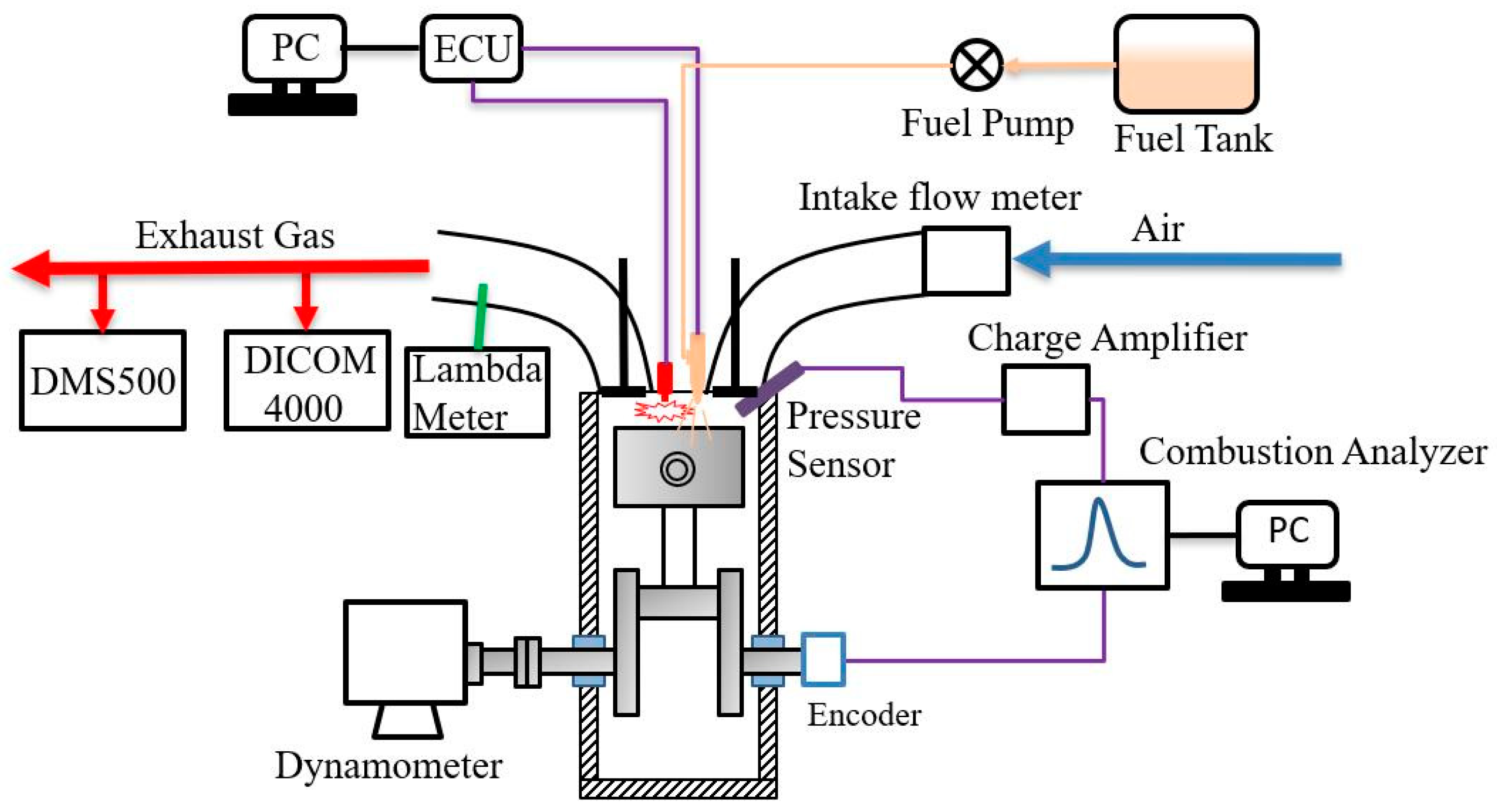
2.1. Engine and Experimental Apparatus

The experimental engine platform used in this study is illustrated in Figure 1. The engine consists of a four-cylinder, four-stroke, spray-guided gasoline direct injection (GDI) engine, and its detailed specifications are listed in Table 1.
In terms of engine parameter control, an electronic control unit (ECU) based on a 16-bit Freescale microcontroller was designed to enable real-time control of ignition timing and fuel injection parameters. The engine load and speed were regulated using an eddy current dynamometer. For measurement equipment, an in-cylinder quartz crystal pressure sensor (Kistler, Switzerland) was employed to monitor real-time cylinder pressure in the first cylinder, synchronized with the crank angle signal from the front end of the crankshaft. These signals were processed by a combustion analyzer (model DS-9110, ONO SOKKI, Japan) to display and record in-cylinder pressure data in real time and calculate combustion-related characteristic parameters and temperature data. Exhaust samples were collected from the exhaust pipe, with the excess air ratio controlled using a Lambda meter and Lambda sensor (BOSCH, Germany). Exhaust gas emissions were monitored using the DICOM 4000 (AVL, Austria) gas analyzer, while particulate concentrations were measured by a Cambustion DMS500 (Cambustion, UK) fast-response particle analyzer. All instruments were calibrated prior to the experiments, and the measurement accuracy of the main equipment is listed in Table 2. During engine operation, the coolant temperature was maintained at 76 ± 2 °C.

2.2. Experimental Methodology

During the experiments, the engine speed and output torque were maintained at 1400 rpm and 40 Nm, corresponding to approximately 20% engine load. The excess air ratio was kept constant at 1.0 under all operating conditions. Four types of fuels were used: M0, M10, M20, and M40. M0 represents pure gasoline, while M10, M20, and M40 refer to methanol–gasoline blends with methanol volume fractions of 10%, 20%, and 40%, respectively. After switching fuels, the injection pulse width was adjusted to ensure a constant load. For each fuel condition, four injection strategies were employed: 10:0, 8:2, 6:4, and 5:5, where 10:0 represents a single injection and 8:2 denotes a mass ratio of the first to the second injection of 8:2. The injection timing of a single injection was set to 60 °CA after top dead center (ATDC), while for two-stage injection, the first and second injections occurred at 60 °CA and 85 °CA, respectively. Under all conditions, the ignition timing was fixed at 16 °CA before top dead center (BTDC), which can eliminate the influence of the ignition timing on the combustion process, and highlight the influence of the difference in the mixing process caused by the different injection ratios, which is conducive to horizontal comparison.
Although a larger methanol addition ratio has been used in previously published papers [7], in this paper, since the spark advance angle remains unchanged, our preliminary test showed that the combustion cyclic variation seriously deteriorates when the methanol addition ratio exceeds 50%; hence, we used M40 fuel. In addition, the engine and test equipment used in this paper have been successfully implemented in previous experimental studies [27]. Therefore, the test plan designed in this paper is considered reliable.
The sampling frequency for particulate emissions was 10 Hz, and the particle concentration data presented were 30 s averages of continuous sampling. Combustion cycle data were collected for 200 consecutive cycles under stable conditions, and the combustion analyzer computed the average combustion characteristic parameters and cyclic variations, expressed as the coefficient of variation (COVIMEP), using the following equation:
COV IMEP = σ IMEP IMEP ¯ × 100 %
where
IMEP ¯ = 1 N i = 1 N IMEP ,
σ IMEP = i = 1 N ( IMEP IMEP ¯ ) N ,
N represents the combustion cycle number, and IMEP represents the indicated mean effective pressure value of each cycle.

3. Results and Discussions

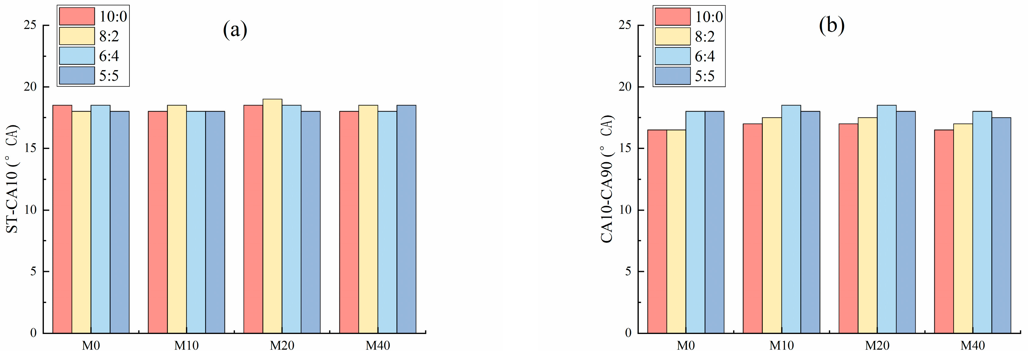
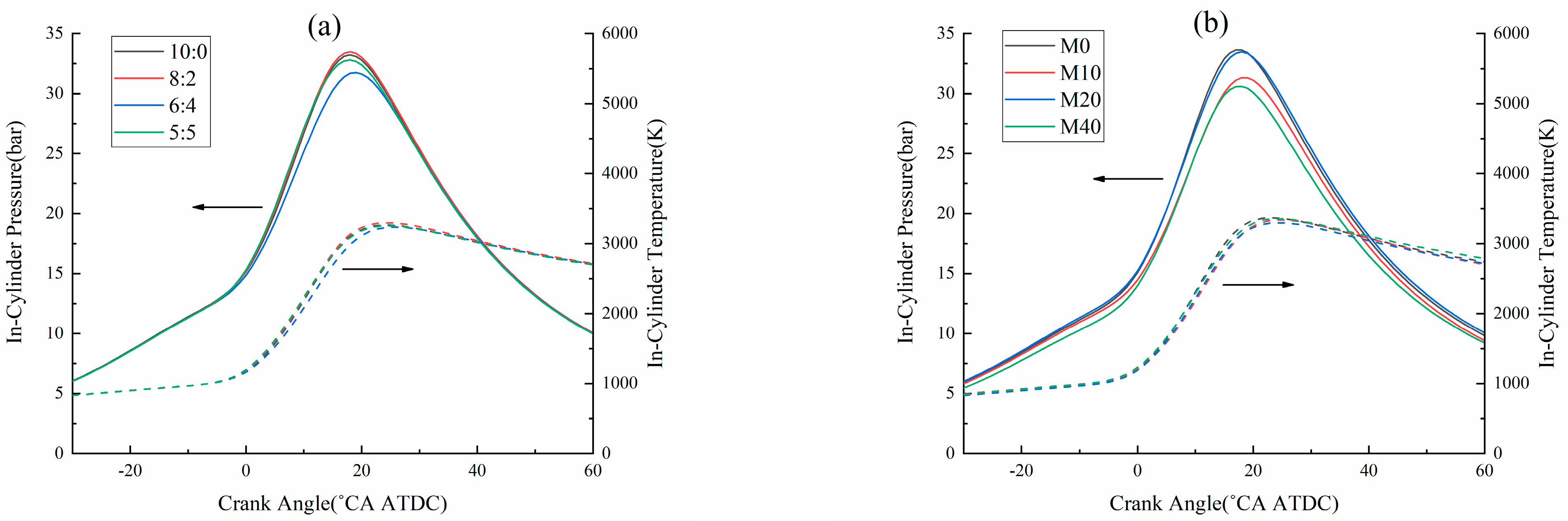
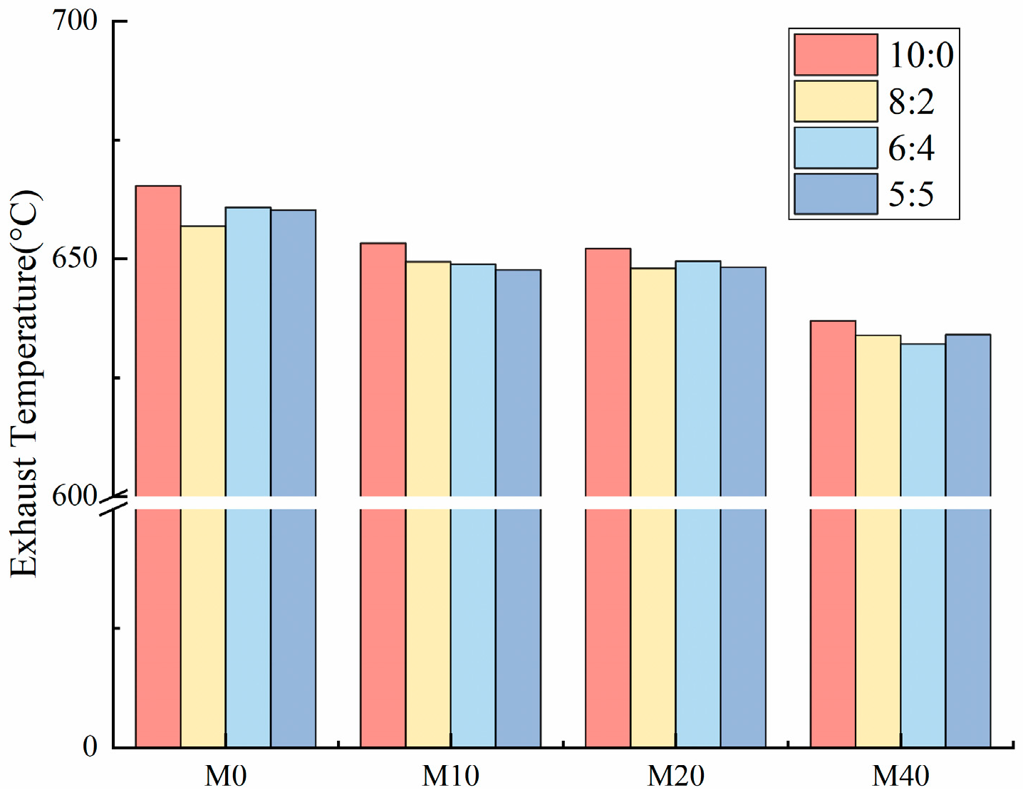
3.1. Effect of Two-Stage Injection on Combustion Characteristics

Figure 2 illustrates the effects of two-stage injection on the flame development (a) and combustion duration (b) for methanol–gasoline blends. The flame development is defined as the crank angle from the spark timing to the point where 10% of the cumulative heat release occurs, while the combustion duration is defined as the crank angle from 10% to 90% of the cumulative heat release. As shown in Figure 2a, compared to single injection, two-stage injection has little impact on the flame development period, which remains approximately 18 ± 0.5 °CA under various methanol blending ratios. Thus, the flame development period is insensitive to both the two-stage injection ratio and methanol blending ratio. In addition, as shown in Figure 2b, under various methanol blending ratios, the combustion duration corresponding to the two-stage injection increases compared with the single injection, and as the second injection ratio increases, the combustion duration first increases and then decreases. When burning pure gasoline or methanol–gasoline blends, the shortest combustion duration occurs at an injection ratio of 8:2. Since the intake strategy and injection timing remain constant across different injection ratios, in-cylinder air motion is largely unaffected. However, changes in the second injection proportion result in different fuel–air mixtures near the spark plug at ignition. This suggests that at an 8:2 two-stage injection ratio, the air–fuel mixture near the spark plug before ignition is optimal for kernel formation and development under these conditions.
Figure 3 demonstrates the effect of two-stage injection on the combustion center for methanol–gasoline blends. In this study, the combustion center is defined as the crank angle corresponding to 50% of the cumulative heat release (CA50), which is critical for engine performance. A more advanced combustion center indicates higher isochoric combustion efficiency. Generally, the engine delivers optimal performance when the combustion center is located at 8–10 °CA ATDC [28]. As shown in Figure 3, under all four fuel conditions, the 6:4 injection ratio yields the most delayed combustion center, i.e., furthest from top dead center (TDC), indicating unfavorable mixture distribution for flame propagation and relatively retarded combustion phasing. Typically, under two-stage injection conditions, the 8:2 injection ratio produces a more advanced combustion center, leading to better engine performance. This is consistent with the research results described in reference [25]. Furthermore, with a fixed two-stage injection ratio, the combustion center advances closer to TDC as the methanol content increases. This is attributed to methanol’s higher oxygen content and laminar flame speed, which accelerate combustion [29].
Figure 4a illustrates the effects of different two-stage injection ratios on in-cylinder pressure and temperature when M20 fuel is burning. As previously discussed, the combustion center for the 8:2 ratio is closest to TDC, resulting in faster combustion. This leads to higher in-cylinder pressure during the piston’s downward stroke and a slightly higher combustion temperature. The 6:4 ratio corresponds to the lowest cylinder pressure, indicating that the mixture distribution under these conditions is less conducive to rapid flame propagation. The specific reasons for this require further simulation analysis. Beyond 30 °CA ATDC, differences in in-cylinder pressure and temperature among various injection ratios become negligible. Figure 4b shows the effects of methanol blending ratios on cylinder pressure and temperature under the 8:2 injection strategy. Among the methanol–gasoline blends, M20 produces the highest cylinder pressure, while blending ratios below or above 20% result in reduced pressure. On one hand, methanol’s high oxygen content enhances flame propagation and combustion speed. On the other hand, methanol’s lower heating value compared to gasoline necessitates a greater fuel quantity under fixed load conditions, leading to a longer injection duration and less combustible mixture available during the rapid combustion phase. Consequently, M20 represents a compromise between these factors, achieving faster combustion when coupled with the 16 °CA BTDC ignition timing. Similar results for M20 (in-cylinder pressure compared to M10 and gasoline) are reported in the literature as well [30]. Beyond 30 °CA ATDC, M40 exhibits a slightly higher in-cylinder calculating temperature.
Figure 5 depicts the impact of two-stage injection on exhaust temperatures for methanol–gasoline blends. The measurement point is the intake position before the turbine. As the methanol blending ratio increases, exhaust temperatures decrease slightly. This is primarily because higher methanol content accelerates the combustion process, advancing the combustion phase and reducing late-stage combustion, thereby lowering exhaust temperatures. Compared to single injection, two-stage injection results in marginally lower exhaust temperatures. As shown in Figure 4a, variations in two-stage injection ratios have minimal impact on in-cylinder pressure and temperature during the later stages of rapid combustion. Additionally, compared to single injection, two-stage injection reduces fuel film on the cylinder walls and piston top, leading to less combustion during the power stroke’s later stages, and lowering the exhaust temperatures.
Figure 6 illustrates the effect of different two-stage injection ratios on the brake-specific fuel consumption (BSFC) of methanol–gasoline blend combustion. To facilitate comparison, the equivalent gasoline BSFC is used to evaluate engine fuel economy under different fuel conditions. This is calculated based on the amount of pure gasoline required to achieve the same heating value as the methanol–gasoline blend. It can be seen that with higher methanol content, the equivalent BSFC decreases, indicating better engine economy. This trend is not influenced by changes in the two-stage injection ratio. For pure gasoline combustion, the variation in BSFC between different two-stage injection ratios is minimal, remaining in the range of 372.98–373.78 g/(kW·h). In the case of methanol–gasoline blending, brake-specific fuel consumption is mainly affected by two factors: exhaust gas temperature and combustion phasing. Lower exhaust temperature means less heat is carried away by exhaust gases, leading to higher fuel conversion efficiency. More advanced combustion phases result in higher isochoric combustion efficiency, with smaller pumping losses. Under a low methanol blending ratio (M10), although the second injection leads to lower exhaust temperatures, the combustion center is delayed. As the second injection ratio increases, the BSFC increases. In contrast, under a higher methanol blend (M20), the ignition timing is better matched with the fuel characteristics, and both injections ensure complete combustion, so the differences in combustion phasing have little effect on overall fuel economy, and the fuel consumption is mainly influenced by the heat loss from the piston and cylinder wall, as well as exhaust losses. In the literature [11], when the added alcohol ratio increases, BSFC also increases. This is because it does not equate the blended fuel consumption under different methanol addition ratios, but simply compares the consumption of the blended fuel mass. Overall, under higher methanol blends, combining an optimized ignition timing with an 8:2 two-stage injection strategy provides the best fuel economy.

3.2. Effect of Two-Stage Injection on Combustion Stability

To assess the impact of different two-stage injection ratios and methanol blend levels on combustion stability, box plots and return maps were used to evaluate the variability between consecutive combustion cycles. Figure 7 shows the cylinder pressure peak values (a) and corresponding crank angle positions (b) for different two-stage injection ratios under the M20 blend. It is evident that at an 8:2 injection ratio, the average cylinder pressure peak value is highest, and the corresponding crank angle position is closest to top dead center (TDC). The interquartile range (IQR) reveals that under the 5:5 injection ratio, the cylinder pressure peak exhibits less overall fluctuation but more anomalies. The peak pressure fluctuation under the 8:2 and 6:4 conditions is almost identical to that of the single injection, with fewer anomalies. In summary, under the M20 fuel condition, 8:2 can increase the cylinder peak pressure value and advance the combustion phase while ensuring combustion stability. The literature [31] believes that the equivalence ratio is an important parameter that affects the combustion cyclic variation, that is, the mixture will usually reduce the cyclic variation as the combustion speed increases.
Figure 8 shows the cylinder peak pressure values (a) and corresponding crank angle positions (b) for different methanol blend levels under the 8:2 injection strategy. The average cylinder peak pressure value is highest for M20. As the methanol blending ratio increases, the fluctuation range of the cylinder pressure peak value does not change much. Additionally, the fluctuation range of the peak pressure position corresponding to the small methanol blending ratio is smaller than that of the large methanol blending ratio, and is close to pure gasoline combustion. The crankshaft angle at which the cylinder peak pressure value corresponding to M20 is smaller. This shows that when the methanol–gasoline blended combustion is fixed at an injection ratio of 8:2, a 20% volume methanol mixed fuel can achieve a higher cylinder peak pressure and a smaller peak pressure phase change, which is most beneficial to combustion stability.
Figure 9 presents the indicated mean effective pressure (IMEP) return maps for M20 (a) and 8:2 (b) conditions. The horizontal axis represents the IMEP value for the i-th cycle, and the vertical axis represents the IMEP value for the subsequent cycle (i + 1). The position of the data points on the map can indicate the value change in IMEP, and the degree of clustering of the data points can indicate the degree of change in IMEP between two consecutive combustion cycles. It is observed that under M20 conditions, the 8:2 two-stage injection results in higher IMEP values compared to other injection ratios, and it closely resembles a single injection. The concentration of the data points of single injection and two-stage injections is basically close, except that of 6:4 is slightly higher, and they are all clustered on the 45° line of the coordinate axis, indicating that the combustion stability under this condition is good and is less affected by the ratio of the two injections. As shown in Figure 9b, under the conditions of the injection ratio of 8:2, the IMEP values corresponding to the fuels with different methanol blending ratios are quite different, and the IMEP change amplitude of two adjacent combustion cycles is relatively small.
The coefficient of variation in IMEP (COVIMEP) is commonly used to evaluate combustion cycle-to-cycle variation. Figure 10 shows the COV of IMEP for different methanol blends and two-stage injection ratios. For all conditions, the combustion cyclic variation is low, with COVIMEP values below 1.5%, indicating that combustion stability is not sensitive to methanol blend ratios or two-stage injection strategies. In other words, using methanol–gasoline blends combined with two-stage injection does not degrade engine power or combustion stability. In summary, using M20 fuel with an 8:2 injection strategy achieves the best combustion stability and higher IMEP values. In the literature [31], as the addition ratio of alcohol fuel increases, the change in COVIMEP is comparable to that present in this paper.

3.3. Effect of Two-Stage Injection on Particulate Emissions

Figure 11 illustrates the changes in particulate number concentration in the exhaust gas under different injection strategies and methanol blend levels. Figure 11a shows the total particulate number concentration, (b) shows the nucleation mode particulate number concentration, and (c) shows the accumulation mode particulate number concentration. In this article, nucleation mode particles refer to small-sized particles with a diameter range of 0–30 nm, which are generally composed of soluble organic matter formed by the condensation of hydrocarbons in the late combustion and exhaust pipe; accumulation mode particles refer to large-sized particles with a diameter range of 20–500 nm, which are generally formed by soot particles formed by local rich mixture combustion through surface growth, agglomeration, and coalescence.
In terms of total particulate number, under pure gasoline and low methanol blend conditions, increasing the second injection ratio initially decreases the particle concentration, then increases it, with the lowest concentration observed at the 8:2 injection ratio. This reduction in particles is due to the reduction in fuel impingement on the cylinder wall and piston top, which lowers the mass of fuel films at the start of combustion. Furthermore, as shown in Figure 5, increasing the second injection ratio also lowers exhaust temperatures, which negatively impacts the oxidation of particles. Under higher methanol blend conditions, particle concentration continues to decrease. This is because the higher methanol content increases the fuel quantity under the same load, leading to longer injection durations. The longer injection causes more spray-wall impingement, resulting in greater fuel film formation and more soot particles [32]. The two-stage injection strategy improves this situation significantly. Moreover, the vaporization heat of methanol contributes to the formation of fuel films, which is why the total particle concentration is higher under higher methanol blends. Compared to single injection, particle concentration is reduced by 36.6%, 46.0%, 4.9%, and 44.5% under the 8:2 two-stage injection strategy for the four fuel conditions. The changes in nucleation mode and accumulation mode particle concentrations follow a similar trend to that of total particulate matter, and in general, the injection ratio of 8:2 can significantly reduce the concentration of both modes of particles.
The particle size distribution under the conditions of M20 (a) and 8:2 (b) is shown in Figure 12. The particle size distribution curves are similar for all conditions, with a peak at approximately 100 nm, indicating that accumulation-mode particles are the dominant form. This suggests that the particles generated during combustion are primarily soot from fuel film combustion, with spray-wall impingement and pool fire contributing significantly to particle formation. Under the M20 condition, the particle concentration across all sizes is relatively low when the 8:2 two-stage injection strategy is used, indicating that the engine’s control parameters are well coordinated, with complete fuel atomization and reduced fuel film combustion. In Figure 12b, it can be observed that with increasing methanol content, the concentration of particulates at all sizes increases, especially for M40, where particle concentrations dramatically rise. This is partly due to longer injection durations, leading to more spray-wall impingement and consequently more soot formation. Additionally, lower exhaust temperatures weaken the oxidation of soot particles. However, for small methanol blends, the increase in particle concentration is less pronounced. Overall, for the test engine, using an 8:2 two-stage injection strategy with low methanol blends can reduce particulate matter emissions. Specifically, compared to single injection with pure gasoline, using M10 with the 8:2 strategy reduces particle concentration by 21.4%, and using M20 with the 8:2 strategy reduces it by 19.7%.

4. Conclusions

This paper studies the effects of different two-stage injection ratios and methanol blending ratios on the combustion characteristics, combustion stability, and particulate matter emissions of a direct injection spark ignition engine. The main conclusions of the study are as follows:
(1)
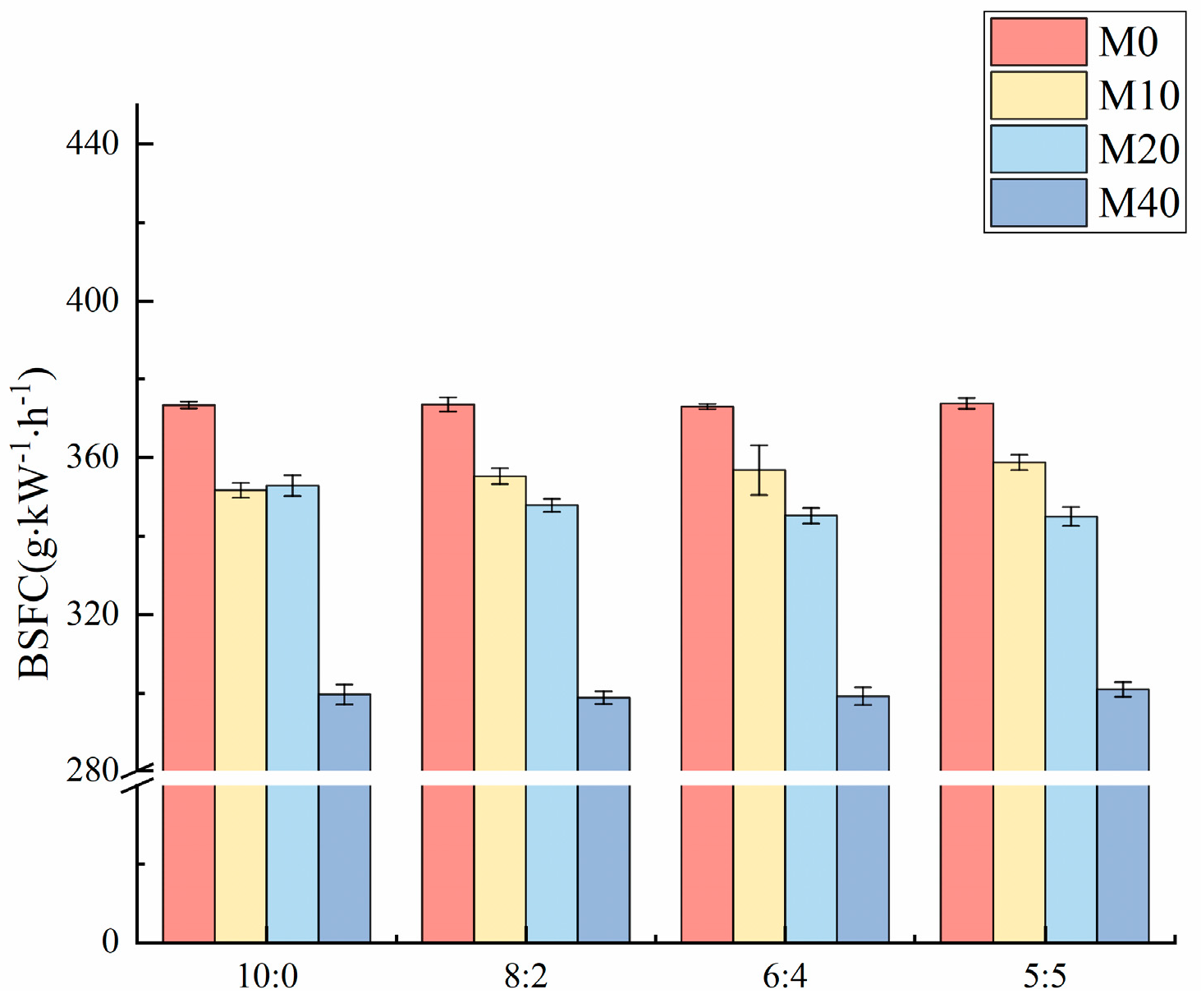
The flame development is not significantly sensitive to changes in two-stage injection ratios or methanol blending ratios. Under two-stage injection, the 8:2 ratio results in the shortest combustion duration and the most advanced combustion center. M20 fuel combined with an 8:2 injection strategy achieves the optimal cylinder pressure for engine dynamic performance.
(2)
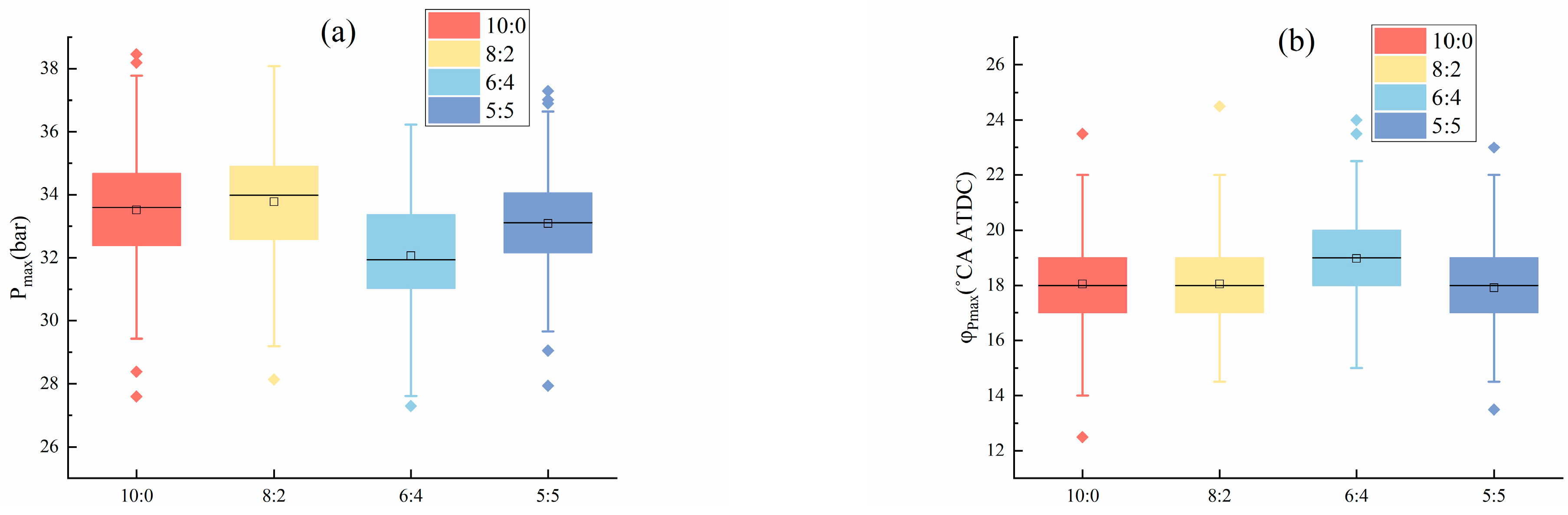
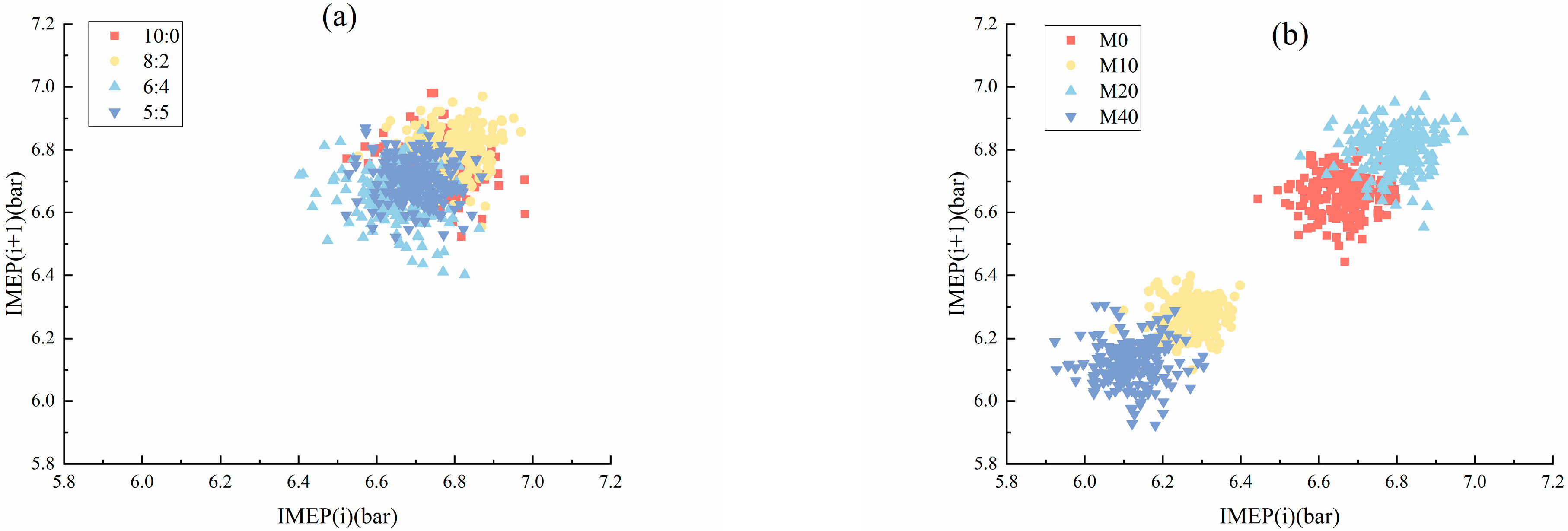
Adjusting the two-stage injection ratio and methanol blending ratio does not negatively affect the fluctuation of cylinder peak pressure or the corresponding crank angle positions. The coefficient of variation under each condition does not exceed 1.5%. The combination of M20 fuel and the 8:2 two-stage injection strategy ensures optimal combustion stability and larger IMEP values.
(3)
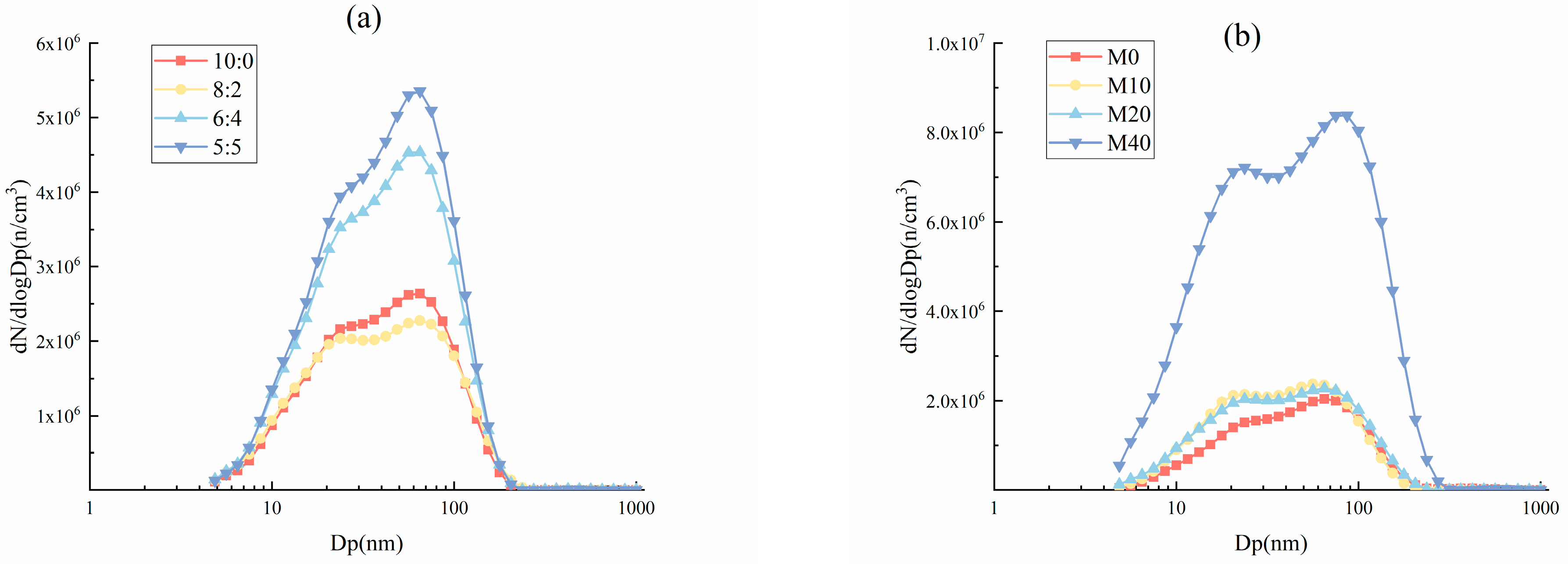
Both two-stage injection ratios and methanol blending ratios impact particle concentrations and size distribution. Compared to single injection with pure gasoline, using low methanol blends and an 8:2 injection strategy reduces particle concentration by approximately 20%.
(4)
For the test engine, an optimal two-stage injection strategy combined with methanol blending can enhance engine performance, maintain combustion stability, and effectively control particulate emissions.

Author Contributions

Conceptualization, M.Z.; methodology, M.Z.; resources, M.Z.; writing—original draft preparation, M.Z. and J.C.; writing—review and editing, M.Z. and J.C. All authors have read and agreed to the published version of the manuscript.

Funding

This research was funded by Natural Science Research Fund Project of Jiangsu Normal University, grant number 20XSRS012; Jiangsu Province Higher Education Basic Science (Natural Science) Research Project, grant number 21KJB470014; Jiangsu Province Industry-University-Research Cooperation Project, grant number BY20230572.

Data Availability Statement

The original contributions presented in this study are included in the article. Further inquiries can be directed to the corresponding author.

Acknowledgments

The authors acknowledge Fangxi Xie’s research group from the College of Automotive Engineering at Jilin University for providing experimental support.

Conflicts of Interest

The authors declare no conflicts of interest.

References

  1. Wang, Z.; Pan, X.; Zhang, W.; Zhao, Y.; Li, H.; Liu, P. The Development Trend of Internal Combustion Engine. J. Phys. Conf. Ser. 2020, 1626, 012139. [Google Scholar] [CrossRef]
  2. Tsiogkas, V.D.; Kleitsas, I.; Kolokotronis, D.; Tourlidakis, A.; Karonis, D. Study of Stoichiometric and Lean Combustion in a Spark Ignition, Direct Injection Optical Engine Using E10 and ETBE20 Fuels; SAE Technical Paper 2022-01-1003; SAE International: Warrendale, PA, USA, 2022. [Google Scholar]
  3. BP. bp Energy Outlook: 2023 Edition. 2024. Available online: https://www.bp.com/content/dam/bp/business-sites/en/global/corporate/pdfs/energy-economics/energy-outlook/bp-energy-outlook-2023.pdf (accessed on 16 January 2025).
  4. Tian, Z.; Wang, Y.; Zhen, X.; Liu, Z. The effect of methanol production and application in internal combustion engines on emissions in the context of carbon neutrality: A review. Fuel 2022, 320, 123902. [Google Scholar] [CrossRef]
  5. Gong, C.; Li, Z.; Sun, J.; Liu, F. Evaluation on combustion and lean-burn limit of a medium compression ratio hydrogen/methanol dual-injection spark-ignition engine under methanol late-injection. Appl. Energy 2020, 277, 11562. [Google Scholar] [CrossRef]
  6. Han, D.; Jiaqiang, E.; Deng, Y.; Chen, J.; Leng, E.; Liao, G.; Zhao, X.; Feng, C.; Zhang, F. A review of studies using hydrocarbon adsorption material for reducing hydrocarbon emissions from cold start of gasoline engine. Renew. Sustain. Energy Rev. 2021, 135, 110079. [Google Scholar] [CrossRef]
  7. Zhou, F.; Yu, J.; Wu, C.; Fu, J.; Liu, J.; Duan, X. The application prospect and challenge of the alternative methanol fuel in the internal combustion engine. Sci. Total Environ. 2024, 913, 169708. [Google Scholar] [CrossRef] [PubMed]
  8. Yu, J.; Kou, C.; Ma, Y.; E, J.; Feng, C. Effect analysis on hydrocarbon adsorption enhancement of different zeolites in cold start of gasoline engine based on Monte Carlo method. Energy 2024, 294, 130738. [Google Scholar] [CrossRef]
  9. Zhou, Y.; Hong, W.; Xie, F.; Su, Y.; Wang, Z.; Liu, Y. Effects of different valve lift adjustment strategies on stoichiometric combustion and lean burn of engine fueled with methanol/gasoline blending. Fuel 2023, 339, 126934. [Google Scholar] [CrossRef]
  10. Shu, M.; Liu, Z.; Wu, F.; Qiu, Y.; Pan, J. Experimental Study on the Combustion and Emission Characteristics of Methanol/Gasoline Fuels in Direct Injection Miller Cycle Gasoline Engines. Int. J. Automot. Technol. 2024, 25, 1517–1527. [Google Scholar] [CrossRef]
  11. Tian, Z.; Zhen, X.; Wang, Y.; Liu, D.; Li, X. Comparative study on combustion and emission characteristics of methanol, ethanol and butanol fuel in TISI engine. Fuel 2020, 259, 116199. [Google Scholar] [CrossRef]
  12. Zhang, Z.; Wen, M.; Cui, Y.; Ming, Z.; Wang, T.; Zhang, C.; Ampah, J.D.; Jin, C.; Huang, H.; Liu, H. Effects of Methanol Application on Carbon Emissions and Pollutant Emissions Using a Passenger Vehicle. Processes 2022, 10, 525. [Google Scholar] [CrossRef]
  13. Nuthan Prasad, B.S.; Pandey, J.K.; Kumar, G.N. Impact of changing compression ratio on engine characteristics of an SI engine fueled with equi-volume blend of methanol and gasoline. Energy 2020, 191, 116605. [Google Scholar] [CrossRef]
  14. Mishra, P.C.; Gupta, A.; Kumar, A.; Bose, A. Methanol and petrol blended alternate fuel for future sustainable engine: A performance and emission analysis. Measurement 2020, 155, 107519. [Google Scholar] [CrossRef]
  15. Sun, Z.; Xu, Q.; Cui, M.; Nour, M.; Li, X.; Hung, D.L.S.; Xu, M. Impact of flash boiling multiple injections timing on the combustion and thermal efficiency of a gasoline direct injection engine under lean-burn. Fuel 2021, 304, 121450. [Google Scholar] [CrossRef]
  16. Jose, J.V.; Mittal, M.; Ramesh, A. Development of a Small-Bore Gasoline Direct-Injection Engine, and Enhancement of Its Performance Using Multiple-Injection Strategies. Sae Int. J. Engines 2021, 14, 115–133. [Google Scholar] [CrossRef]
  17. Li, Y.; Duan, X.; Liu, Y.; Liu, J.; Guo, G.; Tang, Y. Experimental investigation the impacts of injection strategies coupled with gasoline/ethanol blend on combustion, performance and emissions characteristics of a GDI spark-ignition engine. Fuel 2019, 256, 115910. [Google Scholar] [CrossRef]
  18. Xiangyang, W.; Yu, L.; Beiping, J.; Zhaohui, J.; Yan, S.; Fangxi, X. Analysis of the effect of the coupling application of dissociated methanol gas and methanol direct double injection on the engine dilution combustion performance by the Taguchi method. Int. J. Hydrog. Energy 2024, 94, 1453–1463. [Google Scholar] [CrossRef]
  19. Awad, O.I.; Ma, X.; Kamil, M.; Ali, O.M.; Zhang, Z.; Shuai, S. Particulate emissions from gasoline direct injection engines: A review of how current emission regulations are being met by automobile manufacturers. Sci. Total. Environ. 2020, 718, 137302. [Google Scholar] [CrossRef] [PubMed]
  20. Feng, S.; Hong, W.; Li, X.; Xie, F.; Su, Y. The influence of DISI engine control parameters and M15 fuel on regulated and particulate emissions under light-load. Fuel 2020, 276, 118024. [Google Scholar] [CrossRef]
  21. Agarwal, A.K.; Solanki, V.S.; Krishnamoorthi, M. Gasoline compression ignition (GCI) combustion in a light-duty engine using double injection strategy. Appl. Therm. Eng. 2023, 223, 120006. [Google Scholar] [CrossRef]
  22. Lee, Z.; Kim, T.; Park, S. Influences of exhaust load and injection timing on particle number emissions in a gasoline direct injection engine. Fuel 2020, 268, 117344. [Google Scholar] [CrossRef]
  23. Zhang, W.; Ma, X.; Shuai, S.; Wu, K.; Macias, J.R.; Shen, Y.; Yang, C.; Guan, L. Effect of gasoline aromatic compositions coupled with single and double injection strategy on GDI engine combustion and emissions. Fuel 2020, 278, 118308. [Google Scholar] [CrossRef]
  24. Shao, Z.; Wu, P.; Li, W.; Xuan, T.; He, Z.; Wang, Q.; Xu, Q.; Zhang, L. An experimental study on in-cylinder soot formation and flame oscillation of renewable fuel blends in an optical engine. Fuel 2024, 369, 131801. [Google Scholar] [CrossRef]
  25. Lou, D.; Wang, T.; Fang, L.; Xu, Z.; Cheng, C.; Wang, S.; Zhang, Y. Effect of Injection Parameters on Particulate Matter Emission in a Direct Injection Gasoline Engine; SAE Technical Paper 2021-01-0628; SAE International: Warrendale, PA, USA, 2021. [Google Scholar]
  26. Zhang, M.; Cao, J. Effects of Lean Burn on Combustion and Emissions of a DISI Engine Fueled with Methanol–Gasoline Blends. Energies 2024, 17, 4023. [Google Scholar] [CrossRef]
  27. Zhang, M.; Cao, J. Comparative study on combustion and emission characteristics of methanol/gasoline blend fueled DISI engine under different stratified lean burn modes. Fuel Process. Technol. 2024, 266, 108160. [Google Scholar] [CrossRef]
  28. Heywood, J.B. Internal Combustion Engine Fundamentals; McGraw-Hill: New York, NY, USA, 1988. [Google Scholar]
  29. Li, X.; Xie, F.; Han, L.; Gong, Y.; Li, X.; Jiang, B.; Liu, Y. Effect of air and gas dilution on combustion and emission characteristics in alcohol-gasoline fueled SACI engine. Energy Convers. Manag. 2024, 313, 118631. [Google Scholar] [CrossRef]
  30. Sharma, N.; Patel, C.; Tiwari, N.; Agarwal, A.K. Experimental investigations of noise and vibration characteristics of gasoline-methanol blend fuelled gasoline direct injection engine and their relationship with combustion characteristics. Appl. Therm. Eng. 2019, 158, 113754. [Google Scholar] [CrossRef]
  31. Purayil, S.T.P.; Hamdan, M.O.; Al-Omari, S.A.B.; Selim, M.Y.E.; Elnajjar, E. Influence of ethanol–gasoline–hydrogen and methanol–gasoline–hydrogen blends on the performance and hydrogen knock limit of a lean-burn spark ignition engine. Fuel 2024, 377, 132825. [Google Scholar] [CrossRef]
  32. Zeraati-Rezaei, S.; Al-Qahtani, Y.; Herreros, J.M.; Xu, H. Investigation of the effects of split-injection on particle emissions from a Dieseline CI engine. Appl. Energy 2020, 262, 114470. [Google Scholar] [CrossRef]
Figure 1. Schematic of experimental setup [27].
Energies 18 00415 g001
Figure 2. Effects of two-stage injection on the flame development (a) and combustion duration (b) for methanol–gasoline blends.
Energies 18 00415 g002
Figure 3. Effects of two-stage injection on the combustion center for methanol–gasoline blends.
Energies 18 00415 g003
Figure 4. Changes in in-cylinder pressure and temperature under M20 (a) and 8:2 (b) conditions. The solid lines represent in-cylinder pressure and the dot lines represent in-cylinder temperature.
Energies 18 00415 g004
Figure 5. Effects of two-stage injection on exhaust temperature for methanol–gasoline blends.
Energies 18 00415 g005
Figure 6. Effects of two-stage injection on BSFC for methanol–gasoline blends.
Energies 18 00415 g006
Figure 7. Box plots of peak in-cylinder pressure (a) and the corresponding crank angle (b) under M20 conditions.
Energies 18 00415 g007
Figure 8. Box plots of peak in-cylinder pressure (a) and the corresponding crank angle (b) under 8:2 condition.
Energies 18 00415 g008
Figure 9. Return maps between IMEP(i) and IMEP(i + 1) under M20 (a) and 8:2 (b) conditions.
Energies 18 00415 g009
Figure 10. Effects of two-stage injection on COVIMEP for methanol–gasoline blends.
Energies 18 00415 g010
Figure 11. Effects of two-stage injection on particulate emissions: (a) PN-Total; (b) PN-Nucleation mode; (c) PN-Accumulation mode.
Energies 18 00415 g011
Figure 12. Effects of two-stage injection on particle size distribution under M20 (a) and 8:2 (b) conditions.
Energies 18 00415 g012
Table 1. Detailed technical specifications of the test engine [27].
Engine ParametersSpecifications
Engine typeIn-line, 4-Cylinder, 4-Stroke
Combustion SystemSpray-Guided GDI
displacement1.39 L
Bore × Stroke76.5 mm × 75.6 mm
Compression Ratio10:1
Table 2. Measurement uncertainties of devices [27].
DeviceModelUncertainty
DynamometerCW160Torque: ±2 Nm; Speed: ±1 r/min
Pressure sensorZF42±0.3%
Charge amplifierFLEXIFEM PIEZO±0.6%
Crank angle encoderLF-72BM-C05E±0.5%
Air flow meterSENSYCON±0.5%
Fuel flow meterDF-2420±0.2%
Gas analyzerDICOM 4000HC: ±30 ppm; CO: ±0.01%;
NO: ±20 ppm; CO2: ±0.1%
Disclaimer/Publisher’s Note: The statements, opinions and data contained in all publications are solely those of the individual author(s) and contributor(s) and not of MDPI and/or the editor(s). MDPI and/or the editor(s) disclaim responsibility for any injury to people or property resulting from any ideas, methods, instructions or products referred to in the content.

