Abstract
The efficient, low-cost, and large-scale development and utilization of offshore wind energy resources is an inevitable trend for future growth. With the continuous increase in the scale of wind turbines and their expansion into deep-sea locations, there is an urgent need to develop ultra-long, flexible blades suitable for future high-capacity turbines. Existing reviews in the field of blade design lack a simultaneous focus on the two core elements of blade performance calculation and design methods, as well as a detailed evaluation of specific methods. Therefore, this paper reviews the performance calculation and design methodologies of horizontal-axis wind turbine blades from three aspects: aerodynamic design, structural design, and coupled aero-structural design. A critical introduction to various methods is provided, along with a key viewpoint centered around design philosophy: there is no global optimal solution; instead, the most suitable solution is chosen from the Pareto set according to the design philosophy. This review not only provides a concise and clear overview for researchers new to the field of blade design to quickly acquire key background knowledge but also offers valuable insights for experienced researchers through critical evaluations of various methods and the presentation of core viewpoints. The paper also includes a refined review of extended areas such as aerodynamic add-ons and fatigue characteristics, which broadens the scope of the review to touch on multiple research areas and inspire further research. In future research, it is crucial to identify new key issues and challenges associated with increased blade length and flexibility, address the challenges faced in integrated aero-structural design, and develop platforms and tools that support multi-objective optimization design of blades, ensuring the safe, stable, and orderly development of wind turbines.
1. Introduction
Globally, there are abundant offshore wind resources, with estimates suggesting that developing just 10% of these resources could meet the global electricity demand. In China alone, it is conservatively estimated that 1530 GW of floating offshore wind resources remain untapped, presenting enormous potential for growth. The efficient, low-cost, and large-scale development and utilization of offshore wind resources is an inevitable trend for the future. As wind turbines continue to increase in size and expand to deep-sea locations, large megawatt offshore wind turbines have become a focal point of interest. In China’s 14th Five-Year Energy Plan, the development of key technologies for ultra-large offshore wind power equipment is recognized as one of the crucial technological challenges in the field of wind energy utilization. The blade, as a core component of a wind turbine, is crucial for both energy conversion and cost efficiency. To meet the demands of future offshore wind turbines with capacities of 20 MW and beyond, the development of ultra-long blades is urgently needed. As blade sizes increase, their flexibility becomes more pronounced, leading to significant technical challenges, such as severe stall and aeroelastic flutter. Therefore, it is essential to conduct a comprehensive review of wind turbine blade design and provide valuable insights for addressing these issues.
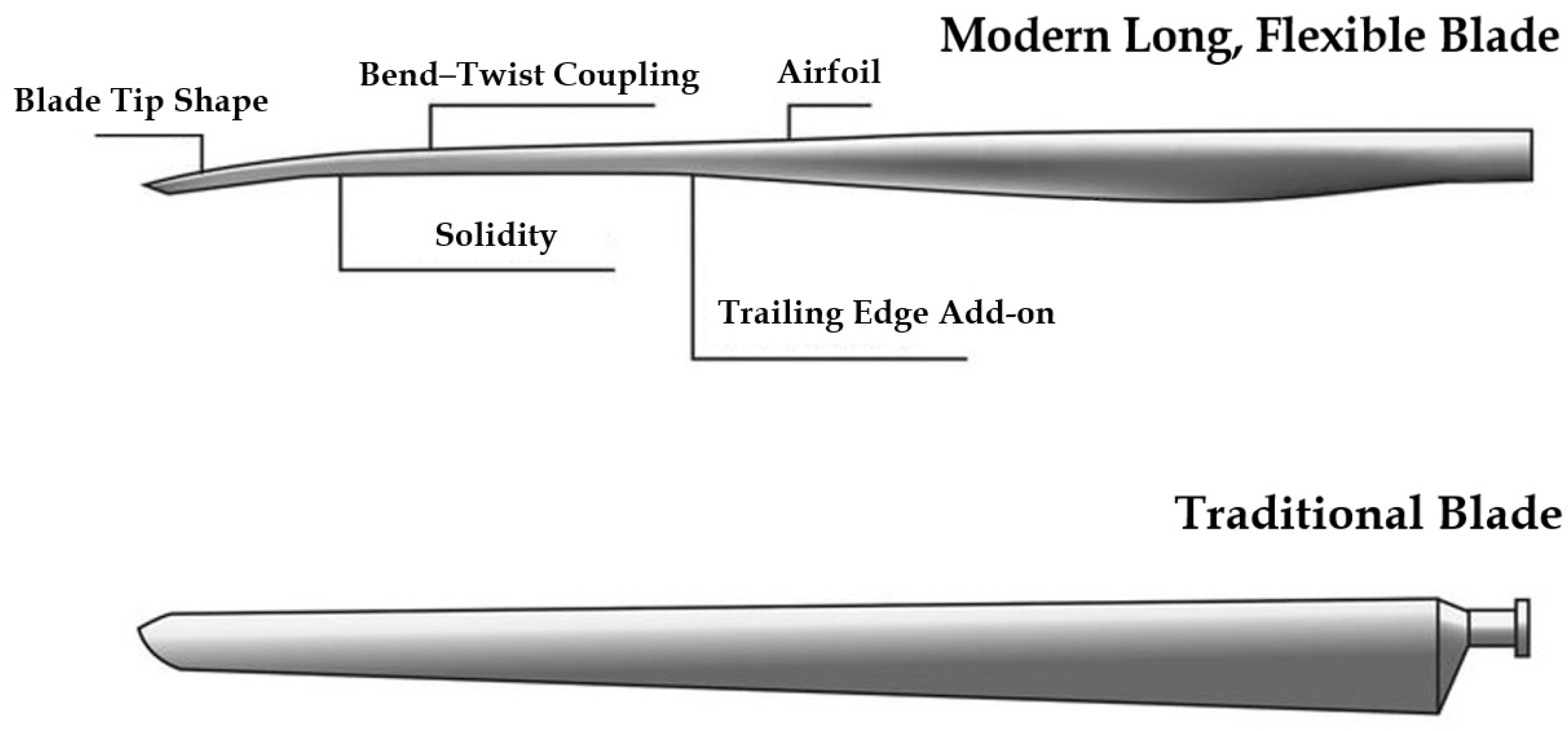
The blade design involves both aerodynamic and structural modules. The aerodynamic module aims to achieve optimal aerodynamic performance through (1) the design and selection of airfoils specifically for wind turbines and (2) the design of aerodynamic shape parameters, such as chord length and twist angle. The structural module focuses on ensuring mechanical integrity by (1) selecting appropriate blade materials and (2) designing sectional configurations, including the placement of the spar cap and the thickness of the skin. A complete blade design must integrate both aerodynamic and structural considerations, making it essential to effectively couple these two modules. The coupling of aerodynamic and structural modules leads to aeroelastic issues, where an elastic structure interacts with the surrounding fluid in a continuous feedback loop. The fluid exerts forces on the elastic structure, causing deformation, which, in turn, affects the fluid domain. This mutual influence makes aeroelasticity a complex phenomenon. In engineering practice, an iterative blade design approach, known as the “aerodynamic design–structural design–load calculation–structural verification” cycle, is commonly used to consider the impact of aeroelastic effects and is referred to as the sequential design method. To improve design efficiency and reduce the reliance on design experience, an integrated design method—determining design parameters based on target performance while closely integrating aerodynamic and structural designs—has also gained increasing attention. Additionally, performance calculation serves as the foundation for blade design. Given a design scheme, the performance parameters are calculated and evaluated. These calculation results then guide adjustments and iterations in the design process, ensuring both the economic viability and safety of the blade. The comparison between a modern blade and traditional blade is shown in Figure 1.
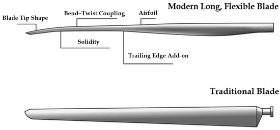
Figure 1.
Wind turbine blade innovation comparing a modern long, flexible blade (top) and a traditional blade (bottom) scaled to the same length [1].
The design of wind turbine blades has always been a key focus in the wind energy field, and numerous review articles have been published to reflect on the progress of blade design. Some researchers conducted reviews on aspects such as variable design, performance enhancement, biomimetic design, performance analysis, and challenges for floating systems for vertical-axis wind turbine blades. However, due to the significant differences between vertical-axis wind turbines (VAWTs) and horizontal-axis wind turbines (HAWTs), the relevance of these reviews to HAWTs is limited [2,3,4,5,6]. Schubel, P.J. et al. provided a comprehensive review of wind turbine blade design, but the scope was so broad that the focus was diluted [7]. Rehman, S. et al. presented a review of blade design and performance calculation using a three-level structure, covering experimental research, numerical analysis, and theoretical analysis. While this structure has strong logical coherence and provides a broad coverage of the existing research, it suffers from a lack of detail regarding specific methods and comparative analysis [8]. Some focused primarily on aerodynamic design, neglecting structural design and coupled aero-structural design [9,10]. Chehouri, A. et al. offered a high-quality review of blade optimization problems, including design variables, constraints, optimization objectives, and tools, but organized the content based on the framework of optimization problems rather than a blade design perspective [11]. Based on the summary and analysis of previously published review articles, it was found that there is a lack of reviews focusing on blade design and performance calculation. Therefore, the framework of this paper is innovative, focusing on two core aspects of blade design: performance calculation and design methodology. It comprehensively reviews blade performance calculation models and design methodologies from three perspectives: aerodynamic, structural, and aero-structural coupling. This review aims to provide newcomers to the blade design field with a clear and concise introduction covering core topics while offering experienced researchers valuable insights through critical evaluations of various methodologies and discussions on the challenges faced in modern blade design.
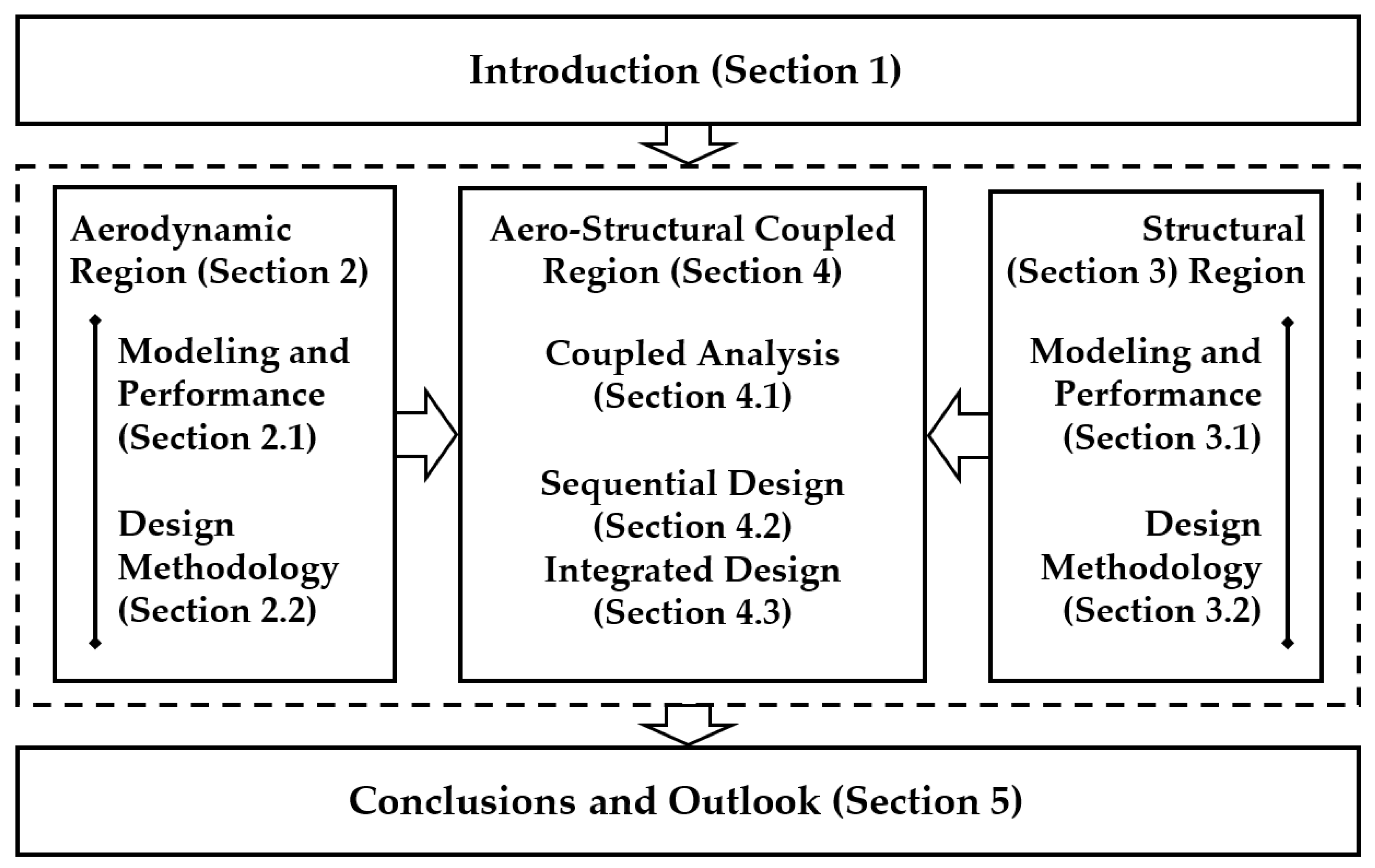
This paper aims to review the performance calculation and design methodologies of horizontal-axis wind turbine blades, offering valuable insights for future research. The paper is structured as follows: Section 2 discusses the aerodynamic module, covering performance calculation models (Section 2.1) and design methodology (Section 2.2). Section 3 addresses the structural module, including performance calculation models (Section 3.1) and design methodology (Section 3.2). Following the detailed introduction of the aerodynamic and structural modules, Section 4 presents the coupled aerodynamic–structural design, focusing on modeling and performance calculation (Section 4.1), sequential design methodology (Section 4.2), and integrated design methodology (Section 4.3). Finally, Section 5 provides conclusions and an outlook for future work. The review structure is shown in Figure 2.
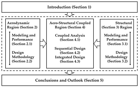
Figure 2.
The logic and structure of this review.
2. Aerodynamic Performance Calculation and Design Methodology
The fundamental aspect of aerodynamic shape design for wind turbine blades is to enhance their aerodynamic performance and load characteristics through optimized shape design.
2.1. Aerodynamic Modeling and Performance Calculation
The mainstream aerodynamic calculation methods are divided into three categories: Blade Element Momentum (BEM) theory, vortex methods, and Computational Fluid Dynamics (CFD).
2.1.1. The Blade Element Momentum (BEM) Theory
The Blade Element Momentum (BEM) theory is the most commonly used aerodynamic theory, being widely applied in both academia and industry due to its high computational efficiency and acceptable accuracy after incorporating correction models.
First, the one-dimensional momentum theory is formulated by introducing the axial induction factor and combining the momentum theorem with Bernoulli’s theorem, with the limitation that only axial flow is considered. Second, by addressing the lack of a rotational velocity component in the wake, a rotating wake model is developed, accounting for the tangential velocity induced by wake rotation and introducing the tangential induction factor a′. This model, however, simplifies the rotor disc. Finally, with the revision assuming an infinite number of blades, the Blade Element Momentum (BEM) theory is established, considering both axial flow and rotating wake effects. The induction factors a and a′ are used to derive the expressions for elemental thrust and torque based on the momentum theory. The local inflow velocity W and inflow angle φ are defined in terms of the induction factors. The tangential force coefficient Ct and normal force coefficient Cn are introduced to establish elemental thrust and torque through aerodynamic force analysis. The expressions for thrust and torque can, thus, be derived by combining the momentum theory with the blade element theory, as shown in Equations (1) and (2).
Sun, Z.Y. et al. conducted an in-depth investigation into the Blade Element Momentum (BEM) theory, focusing on the underlying mechanisms of non-convergence at the blade tip and root, identifying that the term equal to zero in boundary element equations at critical inflow angles is the source of convergence issues [12]. Zhu, W.J. et al. improved the momentum theory by considering the pressure drop effect caused by wake rotation and the influence of radial velocity at the rotor disk in the momentum theory, combining these improvements with Glauert’s and Shen’s tip corrections [13]. Yu, W. et al. examined the impact of unsteady loads on the brake disc wake, leading to modifications of the BEM theory [14]. Cau, K. et al., addressing the unclear definition of highly flexible blades, analyzed the impact of the BEM theory and FVM methods on the aeroelastic response of long blades [15]. Papi, F. et al. pointed out that the integration of the BEM theory with dynamic inflow models can effectively simulate the unsteady aerodynamic response of floating wind turbines [16]. Madsen, H.A. et al. made corrections to the BEM theory to address the power coefficient discrepancies between the inner and outer sides of the rotor [17].
2.1.2. Vortex Methods
Vortex methods are employed to simulate vortex characteristics, making them particularly effective for describing complex phenomena such as rotational flows, wakes, and turbulence. By analyzing the interactions between blades and wakes, these methods further enhance the accuracy of aerodynamic modeling.
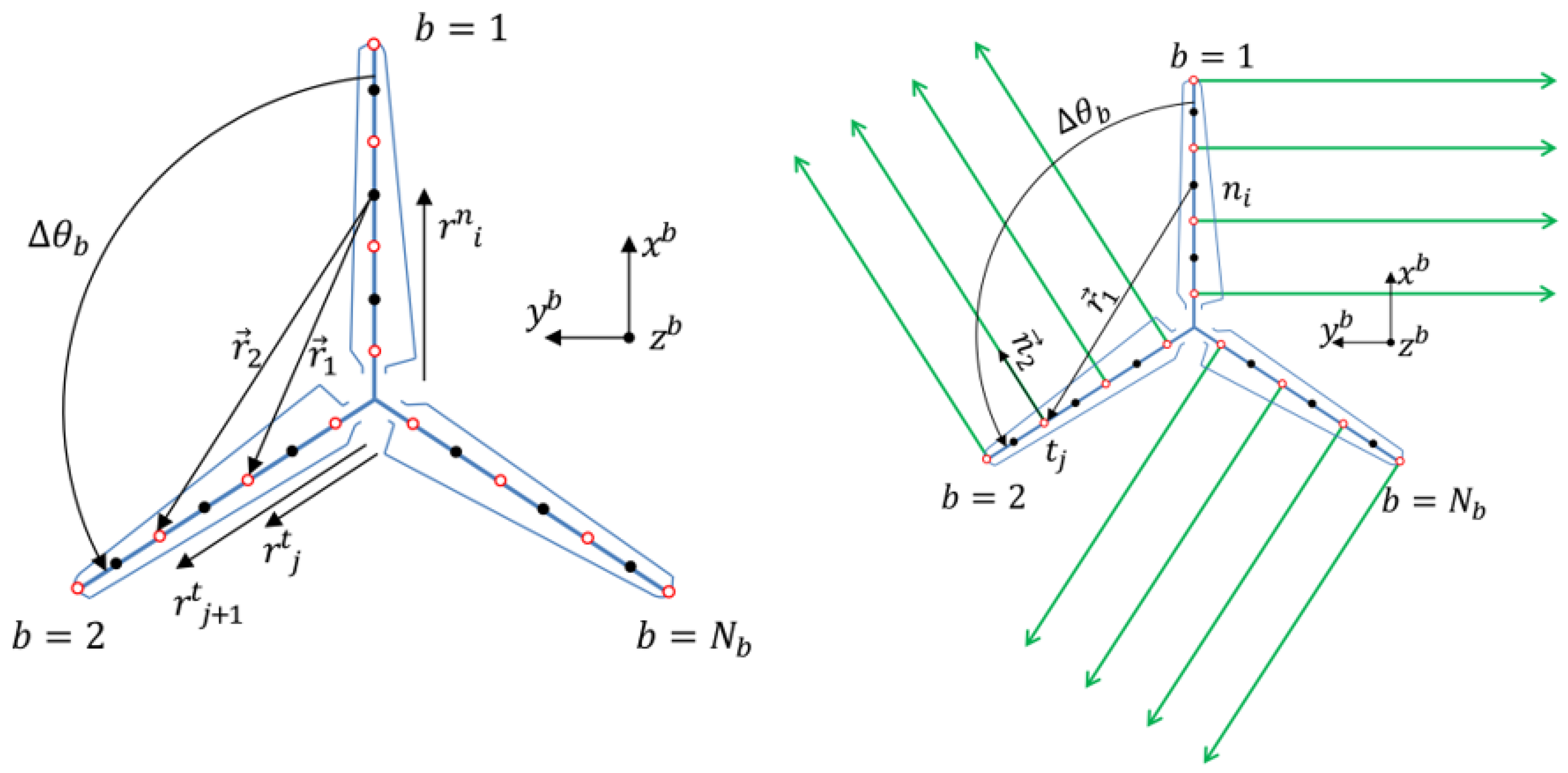
The lifting-line theory is the most simplified vortex method, idealizing blades as lifting lines and calculating lift distribution by introducing induced vortices. It is computationally efficient but has limited accuracy, making it suitable for preliminary aerodynamic analysis. The lifting-surface theory, building upon this concept, simplifies the entire blade into a lifting surface, providing a more precise representation of lift distribution. The free vortex wake method discretizes the wake into multiple free vortex filaments, allowing the wake to evolve freely, offering higher computational accuracy and making it suitable for complex dynamic aerodynamic phenomena, thereby finding broad applications. SugarGabor, O. et al. developed a generalized lifting-line model applicable to lifting surfaces with sweep, twist, and winglets, featuring nonlinear viscous corrections, unsteady and quasi-steady force calculations, wake stretching, and dissipation [18]. Marten, D. et al. developed a lifting-line–free vortex wake method to achieve more accurate unsteady aerodynamic characteristics and to gather detailed information on rotor and flow field evolution [19]. Abedi, H. et al. developed an internal vortex lattice free-wake (VLFW) program to investigate aerodynamic loads, based on inviscid, incompressible, and irrotational flow (potential flow). Airfoil data were incorporated to account for viscosity effects, and a dynamic stall model was used to correct aerodynamic coefficients under unsteady conditions [20]. Dong, J. et al. proposed an improved free-wake vortex ring model to calculate the dynamic characteristics of floating wind turbines, employing a blade bound vortex model and vortex filament-based wake model (Figure 3) for the near wake and a vortex ring method for the far wake, achieving a balance between accuracy and computational cost [21].
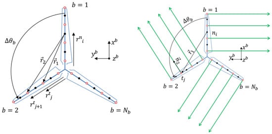
Figure 3.
The blade vortex model [21].
In addition, other forms of vortex methods have been developed. The vortex lattice method, based on an extension of the lifting-line theory, divides the three-dimensional wing surface into small grids, placing vortex lines in each grid to simulate wing surface flow. Lee, H. et al. proposed a nonlinear vortex lattice method to address nonlinear stall and post-stall behaviors, predicting nonlinear aerodynamic characteristics at high angles of attack. The vortex panel method, developed from the panel method and vortex methods, discretizes the flow surface into multiple panels, with vortex points and lines set to simulate the flow field [22]. Prasad, C.S. et al. used Blade Element Momentum and unsteady vortex panel methods for aerodynamic modeling, establishing a free-wake model [23].
2.1.3. Computational Fluid Dynamics (CFD) Methods
CFD methods are the most accurate aerodynamic modeling approaches, providing detailed information about the flow field around the blade by numerically solving the Navier–Stokes (NS) equations, enabling high-fidelity simulations of complex flows. However, the major drawback of CFD methods is their high computational cost, which limits many potential applications. Nevertheless, with advancements in computational power and the increased availability of resources, CFD methods are being applied more extensively.
Popescu, F. et al. conducted RANS modeling, effectively capturing stall inception and cross-blade propagation, and provided reasonably accurate predictions of rotor performance [24]. Cai, X. et al. utilized CFD methods for analysis, applying the sliding mesh approach to handle the interface between moving and stationary components in the flow field, and considered the impact of wind shear, tower shadow, and yaw on the unsteady flow field [25]. Zhou, N.N. et al. employed large eddy simulation (LES) to determine the effects of different inflow conditions (Figure 4), such as uniform inflow, linear wind shear, and turbulent linear wind shear, on aerodynamic loads and near-wake characteristics [26]. Siddiqui, M.S. et al. used CFD methods to assess aerodynamic performance and flow and investigated wake characteristics in conjunction with experimental data [27]. Rezaeiha A. et al. employed high-fidelity CFD methods to analyze blade performance and dynamic loads, systematically studying the effects of parameters such as the tip-speed ratio, Reynolds number, and turbulence intensity on its power and aerodynamic performance [28,29].

Figure 4.
Computational Fluid Dynamics simulation in turbulent shear case [26].
2.2. Aerodynamic Design Methodology
2.2.1. Classical Optimization Design Methodology
The classical design method is based on the BEM theory, utilizing a predetermined thickness distribution and design angle of attack, with the tip-speed ratio as the design variable to derive analytical solutions for the blade chord length and twist angle. The classical aerodynamic design method is well established with low computational demands; however, it relies heavily on extensive engineering experience for the preset aerodynamic parameters and can only optimize for maximum power coefficient, limiting its flexibility.
Okulov, V.L. et al. conducted an experimental comparison of two rotor models designed using different optimization methods: the first employed the impulse method for Glauert optimization, applied independently to each blade section, while the second was based on Betz’s concept of optimizing the rotor by determining a specific circulation distribution over the blade [30]. Ledoux, J. et al. reformulated the Glauert model [31]. Vaz, J.R.P. et al. developed aerodynamic modeling using the Glauert model based on the BEM theory [32].
2.2.2. Multi-Objective Optimization Design Methodology
Compared to the classical design method that only optimizes for the maximum power coefficient, multi-objective optimization design methods have gained increasing attention. Multi-objective optimization aims at achieving the desired performance according to the design philosophy, obtaining aerodynamic shapes through parametric modeling, and conducting performance calculations. The process iteratively approaches the design expectations and eventually yields a Pareto optimal solution set, where trade-offs are made according to the design philosophy. This leads to the core perspective of this paper: there is no global optimum in multi-objective optimization; rather, the most suitable solution is selected from the Pareto set based on the design philosophy.
The advantage of the multi-objective optimization method lies in reducing the dependence on engineering experience, as the diversity of optimization goals supports more complex design requirements. However, the drawbacks include issues with the convergence, robustness, and trade-off between computational accuracy and cost inherent in multi-objective optimization algorithms. Akbari, V. et al. combined the BEM theory with a genetic algorithm to perform aerodynamic multi-objective optimization, aiming to maximize the output power and starting torque [33]. Xu, B.F. et al. used a genetic algorithm to optimize aerodynamic shape parameters, such as the chord length, twist angle, and pre-bend, with the objectives of maximizing the output power and minimizing the flapwise root-bending moment [34]. Assareh, E. et al. compared the computational performance of two hybrid evolutionary algorithms, the Genetic Bee-Based Algorithm (GBBA) and the Harmony Search Bat Algorithm (HSBBATA), using solidity and the power coefficient as optimization objectives [35]. Lee, S.L. et al. conducted multi-objective optimization using the second-order response surface method, with the goals of maximizing the power coefficient and minimizing thrust [36]. Shen, X. et al. applied the NSGA-II algorithm to conduct multi-objective aerodynamic optimization, aiming to maximize annual energy production and minimize aerodynamic loads, using the lifting-surface method as the performance prediction model [37].
2.2.3. Other Optimization Design Methodology
The CFD method offers high computational accuracy, making it suitable for detailed aerodynamic performance analysis and design, but its enormous demand for computational resources has always been a limiting factor. To address this challenge, integrating surrogate models into CFD simulations has gained favor among designers. Wang, H.P. et al. combined the Kriging surrogate model with numerical simulations to optimize the local twist angle of the blade [38]; Pholdee, N. et al. used the CFD method for aerodynamic simulation and introduced Gaussian correlation functions and Kriging surrogate models to reduce the computation time, optimizing the twist angle and rotor axis position of the blade [39]; Sessarego, M. et al. proposed a surrogate optimization method for three-dimensional viscous–inviscid interaction, and the results showed that it could achieve almost the same aerodynamic performance as the classic BEM design method [40].
With the rapid development of artificial intelligence technology, AI techniques such as reinforcement learning and neural networks are gradually being applied to blade aerodynamic design, demonstrating advantages in improving computational efficiency and uncovering the intrinsic relationships between design variables and performance data. Lee, H.M. used an artificial neural network to derive an approximate function between design variables and aerodynamic performance from an aerodynamic database, accelerating the search for the optimal aerodynamic shape with minimum COE (cost of energy) for the blade [41]; Jia, L.Y. et al. proposed a reinforcement learning-based method for efficiently searching the optimal twist-angle distribution, significantly outperforming the traditional genetic algorithm-based methods [42]; Kaya, M. et al. utilized CFD-simulated torque and thrust to train a neural network model, efficiently optimizing the twist distribution and stacking axis position [43]. The advantages and disadvantages of the main aerodynamic design methods for blades are summarized in Table 1.

Table 1.
Summary of blade aerodynamic design methods.
The aforementioned optimization methods mainly focus on optimizing the aerodynamic shape of the blade, but another important aspect involves the optimization of local aerodynamic structures, which can be categorized into aerodynamic add-ons and local modifications. Aerodynamic add-ons refer to the additional structures attached to the blade to improve aerodynamic performance, primarily including vortex generators, Gurney flaps, and winglets. Vortex generators improve the stall characteristics by introducing small-scale flow on the blade surface to suppress or delay flow separation. Moon, H. et al. demonstrated through CFD analysis and experiments that vortex generators enhance aerodynamic performance and increase power output under high wind speeds [44]. Gurney flaps are installed at the blade’s trailing edge to optimize power characteristics without significantly increasing drag, being mostly used for vertical-axis wind turbines. Winglets improve aerodynamic performance by optimizing the flow at the blade tip. Khalafallah, M.G. used CFD methods to evaluate the impact of winglet orientation, inclination, and the twist angle on power characteristics, and the results showed a significant improvement in the power coefficient [45]. The design of aerodynamic add-ons is an important means to improve surface flow and delay stall.
Local modifications involve making localized adjustments to the aerodynamic shape of the blade to meet design requirements. Since the blade tip has a significant impact on the overall aerodynamic performance, most studies focus on the blade tip, with a current research hotspot being the serrated blade tip design. The serrated blade design is inspired by biomimicry, such as mimicking animals like humpback whales, effectively controlling flow separation on the blade surface and reducing turbulence to lower the aerodynamic noise levels. Blade tip modifications are an important approach to reducing aerodynamic noise. Mathew, J. et al. reviewed serrated blade designs for noise reduction in wind turbines and introduced experimental data for validation [46]. Llorente, E. et al. experimentally investigated the impact of trailing-edge serrations on aerodynamic performance [47]. Shehata, A.S. et al. utilized a biomimetic leading-edge design inspired by humpback whales to reduce deflection and improve power capture [48].
3. Structural Performance Calculation and Design Methodology
The main aspects of structural design include material selection, structural form selection, and laminate design. These parameters are used to establish the structural model of the blade, which is then subjected to loads to verify the structural strength. The goal is to achieve minimal weight and cost while ensuring safety and strength.
3.1. Structural Modeling and Performance Calculation Module
Structural modeling and analysis of wind turbine blades require determining the mechanical properties of each section. The process begins with material selection, followed by defining the structural form and laminate design, and, finally, calculating the sectional properties. For material selection, early designs used aluminum or balsa wood. With advancements in materials, glass fiber-reinforced composites are predominantly used for onshore turbines, while carbon fiber composites, due to their high strength, high modulus, heat resistance, low density, and acceptable cost, are increasingly used in large offshore turbines. In terms of structural form, the mainstream approach involves a main spar/double-web/skin configuration, but other forms, such as double spar double web, box beam, leading-edge reinforcement, and trailing-edge bonding beam, are also used. The typical configuration of the blade section is shown in Figure 5.

Figure 5.
The typical configuration of the blade section [49].
To compute the sectional mechanical properties based on the laminate design, there are three main theories: the Classical Laminate Theory (CLT), which is a standard in composite material analysis and considers the section as a stack of multiple laminae with sectional properties derived from the contribution of each lamina; the Variational Asymptotic Beam Sectional Analysis (VABS) method, which simplifies complex three-dimensional, cross-sectional problems into a one-dimensional beam analysis using variational asymptotes, achieving computational precision widely recognized in engineering; and the 3D finite element model (FEM) approach, where sectional properties are indirectly derived through specific deformations under specific loading conditions.
After obtaining the sectional properties, the entire blade can be modeled. There are two main modeling approaches: beam modeling and 3D detailed modeling. Beam modeling leverages the fact that the blade’s length is much greater than its cross-sectional dimensions, making it a thin-walled rod structure. Common beam modeling approaches include Euler–Bernoulli or Timoshenko beams, and more advanced models like variable cross-section beams, rotating beam models, or geometrically exact beam models can be used to enhance precision. This type of modeling offers high computational efficiency and acceptable local accuracy, making it suitable for preliminary design and rapid iteration. The second approach is 3D detailed modeling, which involves creating a full-scale 3D finite element model of the blade. This method provides high accuracy but is computationally expensive, making it appropriate for detailed design and refined verification stages.
Once the blade modeling is complete, structural performance calculations and analyses can be performed. The main structural performance analysis methods for blades include those described below.
3.1.1. Modal Analysis Method
The modal analysis method simplifies the degrees of freedom of the model by representing blade deformation through the linear superposition of modes. It offers high computational efficiency and acceptable accuracy for small deformations, making it suitable for overall wind turbine modeling and preliminary design.
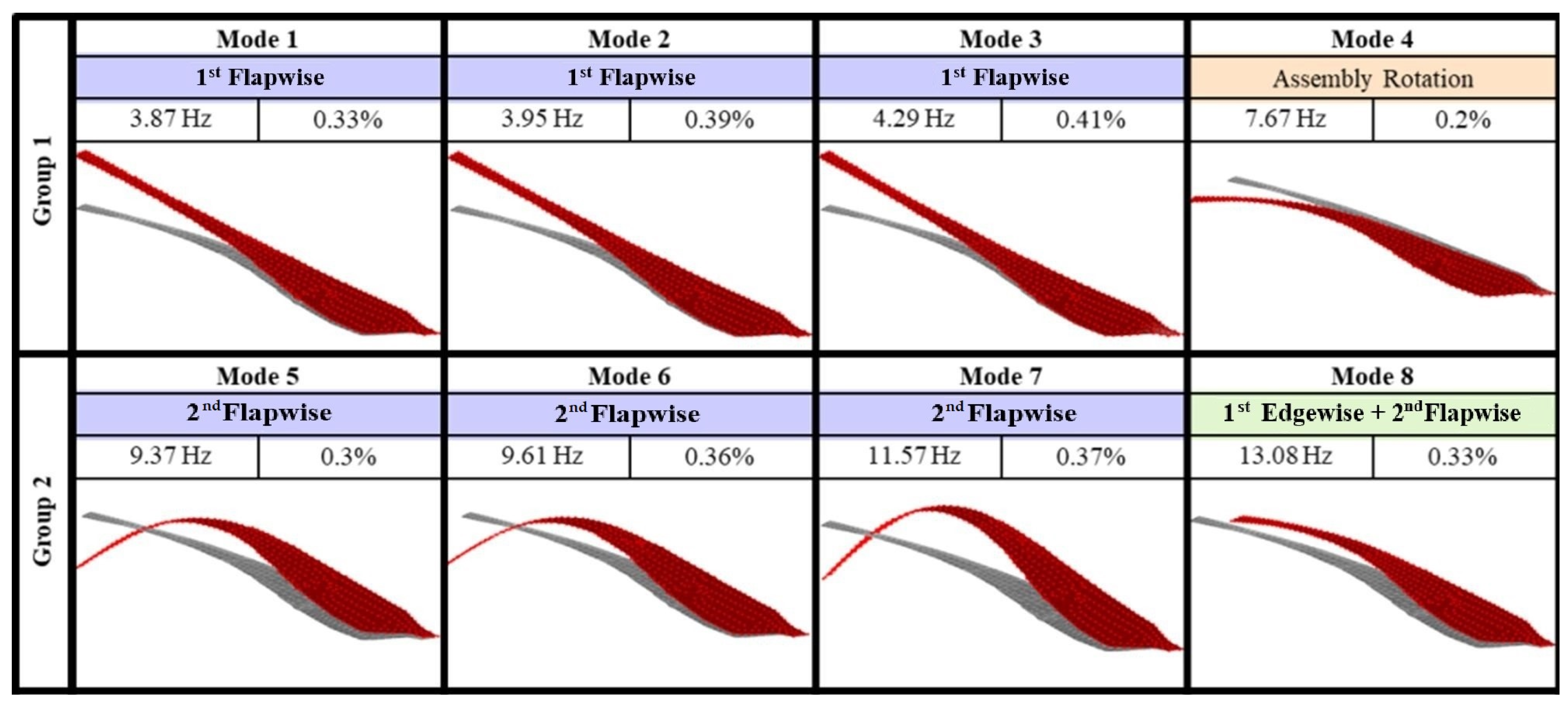
Zheng, Y.Q. et al. analyzed blade vibrations using the modal analysis method, showing that the first six modes are primarily flap modes, and investigated the relationship between tip deformation and load distribution [50]. Chen, Y.C. et al. conducted a comprehensive experimental and numerical study on complex curvature modal shapes and modal coupling dynamics (Figure 6) through triple-modal tests and related FEM simulations [51]. Maktouf, R. et al. performed modal and nonlinear dynamic analyses to study the influence of rotational speed on blade natural frequencies and displacements, proposing an improved finite element formulation based on uncoupled translational and rotational kinetic energy. The results indicated that as the angular speed increased, both the natural frequency and displacement also increased, and the vibration characteristics were significantly sensitive to geometric nonlinearity [52]. Gozcu, O. et al. investigated the capability of modal shapes to represent large deformations, finding that while linear modal shapes could accurately represent flapwise and edgewise deflections, they were insufficient in capturing axial and torsional deflections [53].
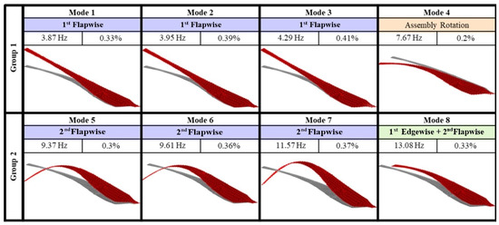
Figure 6.
Mode shapes of test [51].
3.1.2. Multibody Dynamics Method (MBD)
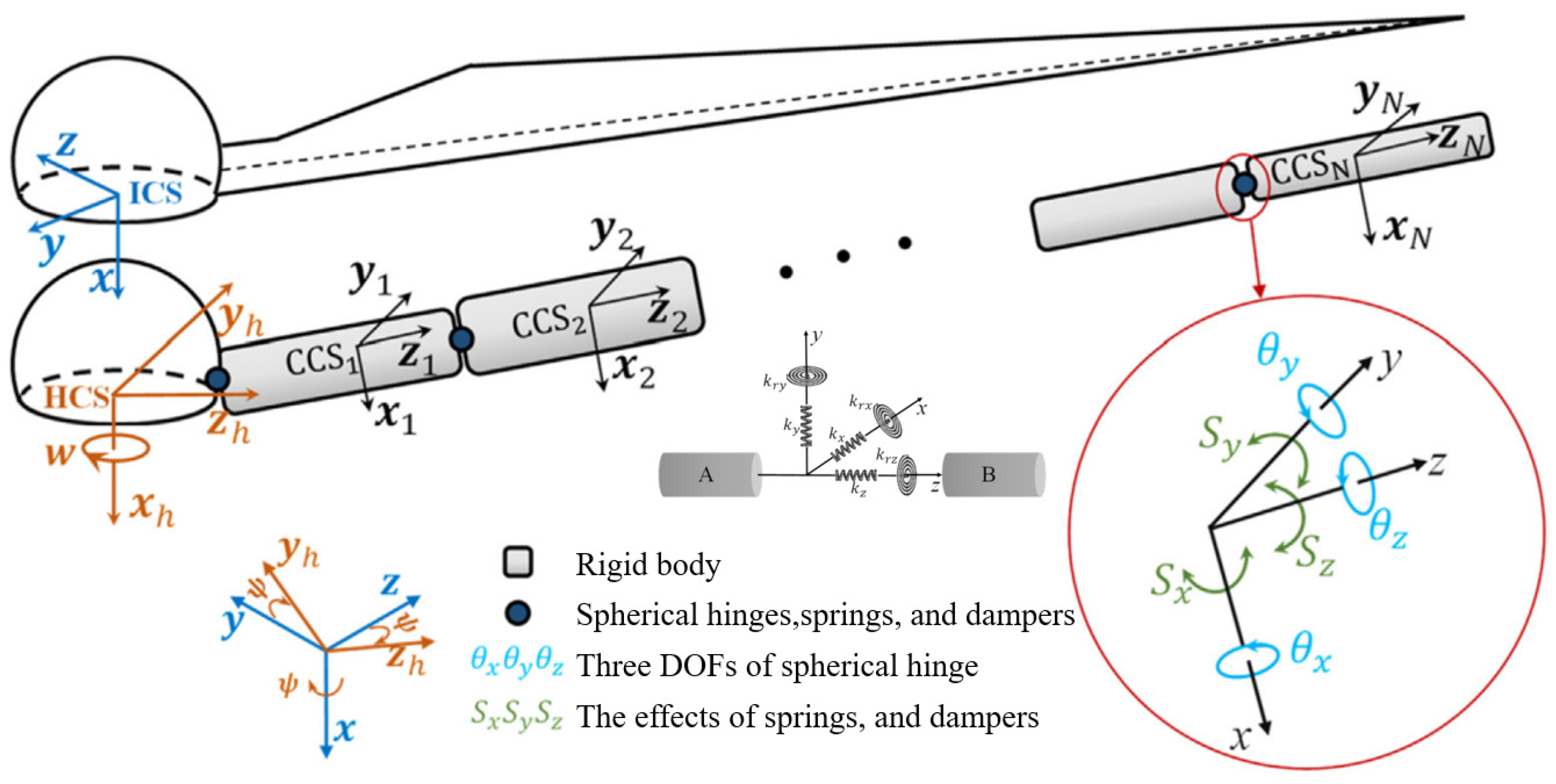
The multibody dynamics (MBD) method is an analytical approach used to study the dynamic behaviors of systems composed of multiple connected rigid or flexible bodies. It is suitable for modeling the entire wind turbine system. Compared to the modal analysis method, MBD reduces constraints on deformation at different spanwise positions of the blade, allowing for more degrees of freedom. However, it cannot provide detailed deformation information for the blade. MBD offers higher computational accuracy and moderate computational time compared to modal analysis. Xu, J. et al. used a rigid multibody dynamics method (Figure 7) to analyze the aeroelastic BaMB model [54]. Horcas, S.G. et al. conducted a numerical simulation study of vibration based on the multibody finite element method [55]. Tang, D. et al. derived system control equations for aeroelastic effects using the multibody dynamics method and the free vortex wake method and proposed a quasi-Newton method suitable for contemporary searches to solve these nonlinear equations based on the inverse BFGS method [56].
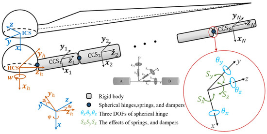
Figure 7.
Multibody dynamics model [54].
3.1.3. Finite Element Method (FEM)
The finite element method divides the blade structure into mesh elements, retaining a significant number of model degrees of freedom to enable detailed analysis, providing more comprehensive deformation details. This method offers the highest model accuracy but also requires substantial computational resources, making it suitable for refined blade design and detailed structural verification.
Hamdi, H. et al. developed a beam finite element model of large elastic deformation of the blade under aerodynamic, centrifugal, gyroscopic, and gravitational loads [57]. Balokas, G. et al. established a finite element model of the blade’s load-carrying box beam to analyze its failure and fracture mechanisms [58]. Finnegan, W. et al. used ABAQUS, ANSYS, and CALCULIX to develop three independent finite element numerical models and conducted static tests in the edgewise and flapwise directions [59]. Haselbach, P.U. et al. implemented a structural modeling approach combining shell and solid elements, connecting solid brick elements with shell elements through multi-point constraints, and discretizing the trailing-edge adhesive line. This approach overcame the shortcomings of pure shell elements and reliably predicted the structural response under ultimate loads [60]. Theotokoglou, E.E. et al. investigated internal, mechanical design, and material selection issues under static flap loads through finite element analysis [61].
3.1.4. Generalized Damage Analysis
The wind turbine blade operates in a complex environment, has a long service life, and requires high reliability, which raises higher demands for life-cycle assessment. The purpose of blade damage analysis is to identify, assess, and predict potential damage that may occur during operation to ensure the safe, stable, and long-term operation of the wind turbine. Based on blade structure modeling and performance calculations, a comprehensive damage analysis can be conducted. Blade damage mainly includes structural damage, such as buckling, fracture, and delamination, and surface damage, like erosion, wear, and corrosion. The causes of blade damage include cumulative fatigue damage caused by long-term cyclic loads, excessive loads, stress, and strain under extreme conditions; blade fractures and material burning or melting caused by lightning strikes; and long-term impacts from environmental factors such as temperature, salt spray, and UV radiation on blade durability. Therefore, fatigue analysis and the suitability of repair are key components of blade damage analysis.
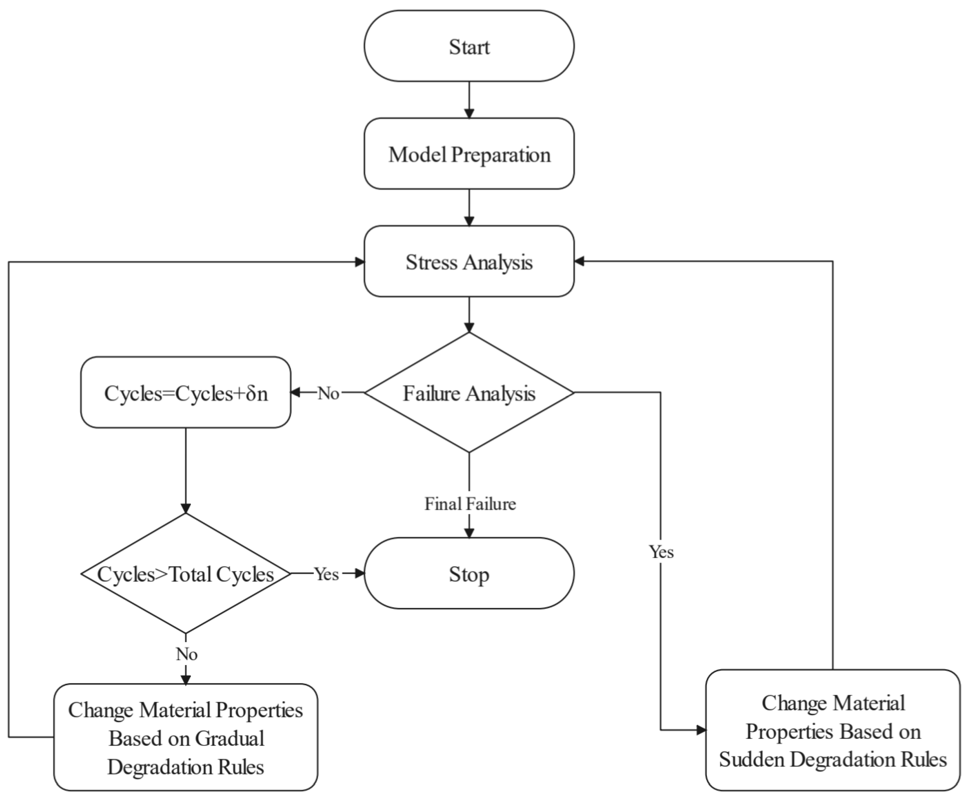
The blade operates in a constantly changing wind environment, bearing long-term, unsteady cyclic loads. According to the classical Miner’s linear cumulative damage theory, when the damage from different load cycles accumulates to a certain extent, fatigue failure occurs, seriously affecting the service life of the blade. In the book “On the Fatigue Analysis of Wind Turbines”, Sutherland, H.J. comprehensively introduces the damage mechanisms, damage sources, damage assessment, and solutions for wind turbine fatigue [62]. Shokrieh, M.M. et al. developed the stiffness degradation method as an alternative to Miner’s linear cumulative damage theory (Figure 8), which can simulate load sequences and load history [63]. Marin, J. et al. analyzed the causes of failure based on damage inspection data [64], while Kong, C. et al. presented a specific fatigue analysis process and conducted practical blade fatigue assessment, providing valuable insights [65].
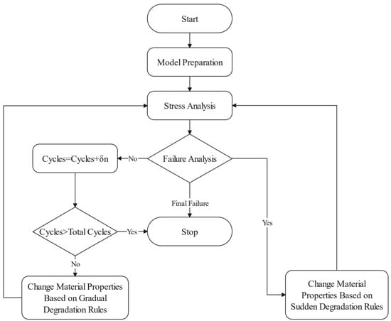
Figure 8.
Flowchart of accumulated fatigue damage modeling [63].
The complex operating environment also poses challenges to the suitability of blade repair, especially as many operational wind turbines are approaching the end of their service life. Surface roughness is an important factor, as it affects aerodynamic performance and can induce larger flow structures, thereby increasing vibration loads, which is detrimental to the safe and efficient operation of wind turbines. Kelly, J. et al. conducted a numerical study on the impact of blade roughness on wind turbine performance and annual energy production and proposed improved control strategies to mitigate negative effects [66]. Fiore, G. et al. performed numerical simulations of the collision between blade surfaces and air particles, exploring the relationship between impact location and erosion rate [67]. Holzinger, C. et al. developed a numerical flow simulation method to predict erosion and torque loss, laying the groundwork for evaluating the economic efficiency of repairs. The results indicate that as long as the surface roughness model is accurate, the NS equations can accurately predict flow separation and losses, supporting the analysis of the impact of surface roughness on aerodynamic characteristics [68].
3.2. Structural Design Methodology
3.2.1. Classical Optimization Design Methodology
The classical structural design method first involves parametric modeling of the blade structure and lamination, then uses performance calculation models to obtain the sectional properties and overall blade characteristics, followed by structural verification to meet the design requirements. Liao, C.C. et al. conducted structural optimization using the thickness and position of the spar cap as design variables, with the objective of minimizing the mass. To reduce the computational cost, the load condition that produced the maximum deflection in the initial design was used for loading [69]. Sjolund, J.H. et al. conducted gradient-based sizing optimization using the ply group thickness as the optimization variable, employing the sequential linear programming method to solve the semi-analytical gradient problem. This approach reduced the blade mass and active constraints in multiple load directions while ensuring manufacturability [70].
3.2.2. Multi-Objective Optimization Method
The mainstream approach to structural multi-objective optimization involves introducing multiple interdependent optimization objectives and multi-objective optimization algorithms based on structural parametric modeling to design the overall structural performance of the blade. Hu, W.F. et al. performed optimization using a multi-objective evolutionary algorithm with the goal of minimizing the material cost and blade weight while meeting the stress ratio, tip deflection, and laminate layup requirements, along with conducting fatigue life evaluation and modeling [71]. Hu, W. et al. developed an automated optimization method for blades based on limit state analysis, with the cost and blade weight as the multi-objectives and the ultimate strength, fatigue failure, and critical deflection as constraints. The optimization combined finite element analysis with an evolutionary algorithm [72]. Fagan, E.M. et al. conducted structural design using a multi-objective genetic algorithm [73]. Dal Monte, A. et al. carried out structural optimization using material selection and its positioning in the skin layout as design variables, applying a multi-objective genetic algorithm [74].
3.2.3. Other Optimization Design Methodologies
The topology optimization method is an optimization design approach based on mathematical algorithms, aimed at altering and optimizing the distribution of materials within the structure to achieve optimal material utilization and distribution, thereby improving the stiffness-to-weight ratio of the blade. This method has garnered significant attention from researchers. Buckney, N. et al. proposed an improved structural layout using topology optimization techniques and also developed dimensionless structural shape factors to quantitatively evaluate structural efficiency under asymmetric bending [75]. Forcier, L.C. et al. conducted phased topology optimization of the blade structure considering factors such as non-tapered cross-sections and blade twist, further constructing a complete blade structural shell model. Composite material sizing optimization was performed, with minimum mass as the objective, under constraints of deflection, composite strength, and structural stability [76]. Zhu, J. et al. improved a structural design to reduce the mass using topology optimization. First, an improved internal structure configuration was found with minimum compliance as the objective. Then, based on the topology optimization results, a shell finite element model was established to analyze the impact of characteristic parameters on the performance. Finally, sizing optimization was carried out with minimum mass as the objective, subject to constraints on strain, deflection, vibration, and buckling limits, achieving a slight mass reduction [77]. Sorensen, S.N. et al. proposed a topology optimization method for discrete material and thickness optimization of laminated composites, known as the DMTO method [78]. Albanesi, A.E. et al. reduced a blade’s mass by combining evolutionary algorithms and topology optimization in an alternating manner [79].
AI technology has also been applied to blade structural design. Nicholas, P.E. et al. introduced an artificial neural network to replace finite element analysis, optimizing blade layups to enhance buckling strength [80]; Albanesi, A. et al. used artificial neural networks for blade weight reduction design, effectively reducing a blade’s weight and computational cost [81]. The advantages and disadvantages of the main aerodynamic design methods for blades are summarized in Table 2.

Table 2.
Summary of blade structural design methods.
4. Coupled Aero-Structural Performance Calculation and Design Methodology
A complete blade design requires both aerodynamic design parameters and structural design parameters. Therefore, after introducing the aerodynamic and structural design, this chapter presents aero-structural coupling analysis methods, with a focus on wind turbine aeroelasticity, and further introduces aero-structural coupling design methods. Aeroelasticity can be categorized into static and dynamic aeroelasticity, while aero-structural coupling design methods can also be classified into sequential design and integrated design based on different coupling approaches.
4.1. Aeroelastic Modeling and Performance Calculation Module
Aeroelasticity represents a classic example of fluid–structure interaction, where the motion of an elastic structure within a fluid results in reciprocal effects between the fluid and the structure. The fluid applies forces that cause the structure to deform, and this deformation subsequently influences the fluid flow, creating an ongoing feedback loop.
4.1.1. Static Aeroelasticity Performance
Static aeroelasticity refers to the interaction between blade structural deformation and aerodynamic forces under static loading and uniform inflow. It primarily includes analyses such as power coefficient evaluation and steady-state power curve calculation under steady conditions. The level of idealization is relatively high, and the problem complexity is relatively low. Hoogedoorn, E. et al. conducted static aeroelastic analysis using X-Foil and MATLAB PDE [82]. Zhu, J. et al. carried out static aeroelastic analysis by coupling the BEM theory with a 3D finite element method and performed multi-objective optimization aimed at increasing annual energy production (AEP) and reducing mass [83]. Rafiee, R. et al. established a 3D FEA model and iterated between aerodynamic loads and blade deflection shapes until convergence to evaluate the changes in induced stress under static aeroelastic conditions [84].
4.1.2. Dynamic Aeroelasticity Performance
Dynamic aeroelasticity refers to the calculation of aeroelastic response and stability of blades under actual inflow conditions and during turbine operation. It requires consideration of factors such as wind shear and turbulence intensity in the actual inflow, as well as operational control parameters like yaw and pitch. The model is closer to real-world conditions, and the problem complexity is relatively high.
Wang, L. et al. conducted research on aeroelastic response simulation methods under typhoon conditions [85]. Filsoof, O.T. et al. established a high-fidelity linear steady-state aeroelastic model to determine the presence of aeroelastic instability or critical low-damping modes [86]. MacPhee, D.W. et al. analyzed the aeroelastic response of a flexible morphing blade using a fluid–structure coupling solver based on the finite volume method [87]. Jeong, M.S. et al. focused on the dynamic stability of the blade, conducting fluid–structure coupling analysis while considering geometric nonlinearity. Structural analysis was performed using a finite element method based on large deflection beam theory, and stability analysis used an aerodynamic model combining Greenberg’s extension to Theodorsen’s strip theory and the BEM theory [88]. Manolas, D.I. et al. performed aeroelastic simulation analysis based on the finite element method to evaluate the impact of structural nonlinearity due to large blade deflections on loads. The results indicated that bend–twist coupling was the primary nonlinear effect leading to load discrepancies [89].
4.2. Sequential Design Methodology
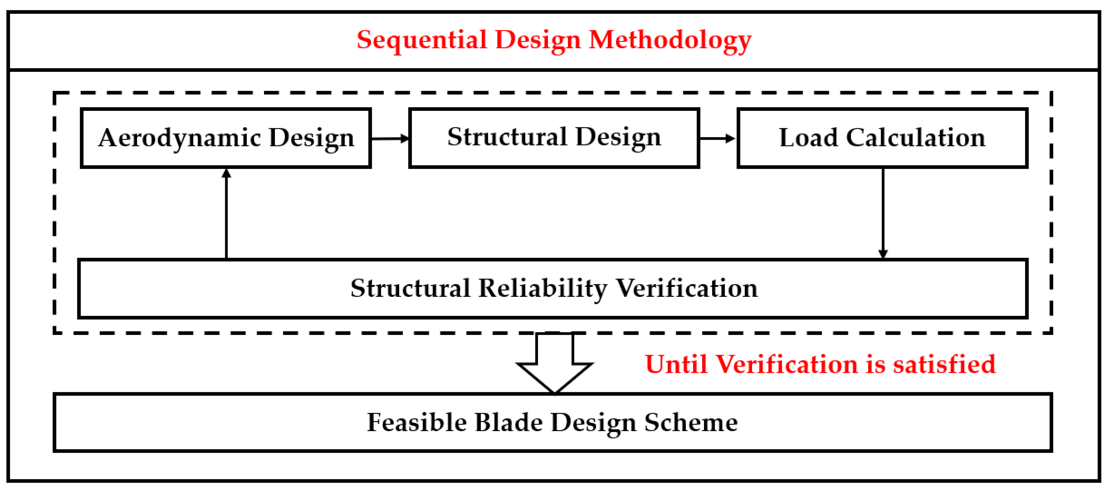
Sequential design involves alternating between aerodynamic and structural design stages, with each subsequent stage adjusted based on the results of the previous one. This process results in delayed interactions between aerodynamic and structural parameters, leading to a longer design cycle. Typically, the aerodynamic design stage employs classical aerodynamic models, deriving analytical solutions for the blade’s aerodynamic shape based on the Blade Element Momentum (BEM) theory. The structural design stage then uses classical beam theory and laminated composite plate theory to perform material selection, design the structural form, and outline the ply layout for the blade. Aerodynamic and structural parameters are calculated, verified, and iteratively adjusted until all constraints are met. The flow of sequential blade design methodology is shown in Figure 9.
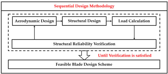
Figure 9.
Sequential blade design methodology.
In engineering design, the sequential design method, centered on the iterative calculation process of “aerodynamic design–structural design–load calculation–structural reliability verification”, is widely used. This process is straightforward and clear, and as design experience accumulates, the quality of feasible solutions and the iteration speed improve. However, with the rapid development of the wind power industry, blade delivery timelines have significantly shortened, imposing higher demands on the design cycle and hindering the rapid involvement of developers in the design process due to the high experience requirements.
4.3. Integrated Design Methodology
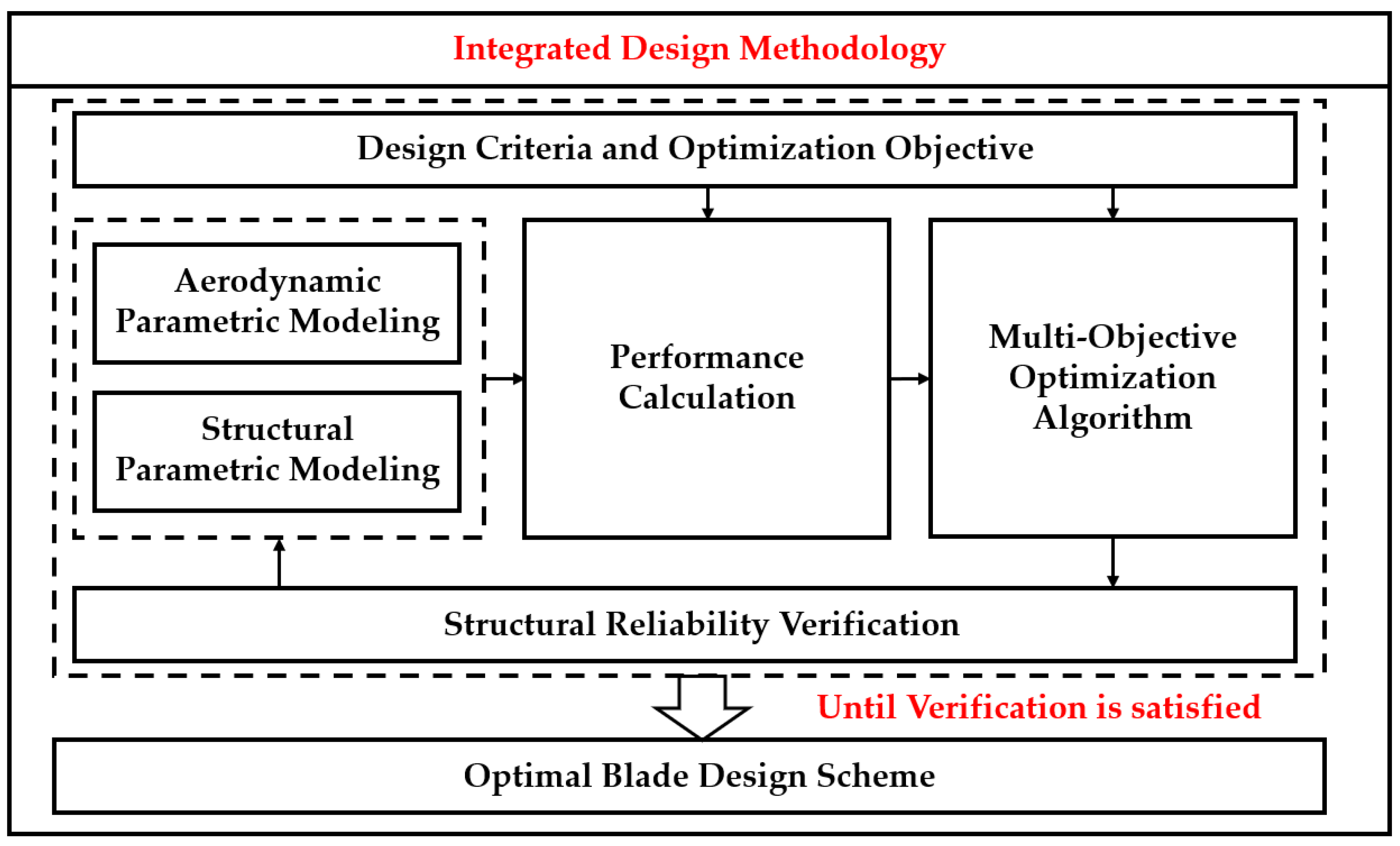
Integrated design, also known as aero-structural integrated design, involves simultaneous parametric modeling of the blade’s aerodynamic shape and structural configuration, enabling concurrent aerodynamic and structural design. This approach allows for real-time interactions between aerodynamic and structural parameters, resulting in a shorter design cycle. Typically, parametric modeling is performed for both aerodynamic shape and structural ply layout, followed by aerodynamic and structural calculations to obtain the blade performance parameters. A multi-objective optimization design method is then used to coordinate and optimize numerous variables and constraints, progressively moving towards the optimal design. Due to its high design flexibility, shorter design cycle, and reduced reliance on experience, strongly coupled multi-objective, aero-structural optimization design has become a current research focus in blade optimization design. Coupled aero-structural, multi-objective optimization design simultaneously considers the optimization of both aerodynamic and structural domains. This approach incorporates diverse and practical design philosophies with fewer restrictions, addressing aerodynamic and structural optimization goals, as well as more integrated economic indicators. The constraints are comprehensive, resulting in an optimal design solution with higher quality and greater engineering application value. However, coupled aero-structural, multi-objective optimization also faces numerous challenges, such as the computational cost skyrocketing due to the large number of design variables, difficulties in meeting the convergence and robustness requirements of optimization algorithms, and challenges in effectively balancing and coordinating multiple cross-domain optimization objectives. The flow of integrated blade design methodology is shown in Figure 10.
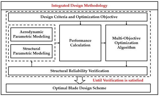
Figure 10.
Integrated blade design methodology.
Wu, J.H. et al. conducted optimization with engineering economic indicators such as LCOE and net present value as the objectives, resulting in sacrifices in aerodynamic performance to reduce loads and costs [90]. Jiang, Y.D. et al. used multi-objective genetic algorithms for blade design, with optimization objectives of power generation, tip deflection, and blade self-weight [91]. Xu, Y.Y. et al. carried out coupled aero-structural optimization with the objectives of minimizing material usage and achieving optimal power efficiency through optimal structural strength, developing a three-dimensional time–domain unsteady panel method [92]. Meng, R. et al. performed optimization with annual energy production and blade mass as the objectives, proposing a new adaptive win–stay–lose–shift game method, where aerodynamic and structural goals are treated as two game players with interacting and conflicting interests. A notable feature is the adaptive adjustment of the strategy space for players and behavior switching between competitive and cooperative modes according to game rules [93]. Li, Y.J. et al. used power coefficients, structural strength, and aerodynamic noise as the optimization objectives, conducting optimization by combining a multi-objective particle swarm optimization algorithm with the finite volume method [94]. Fischer, G.R. et al. applied an improved genetic algorithm to perform multi-objective optimization with objectives of annual energy production, rotor thrust, and blade mass [95]. Zhu, J. et al. conducted multi-objective optimization with annual energy production, blade mass, and rotor thrust as the objectives using the NSGA-II algorithm [96,97].
5. Conclusions and Outlook
This paper presents a review of the design of horizontal-axis wind turbine blades, covering three levels: aerodynamic design, structural design, and coupled aero-structural design. In terms of aerodynamic design, the mainstream methods for aerodynamic modeling and performance calculation include the Blade Element Momentum (BEM) theory, vortex methods, and Computational Fluid Dynamics (CFD). The aerodynamic optimization methods are mainly based on classical design approaches and multi-objective optimization design methods. For structural design, the main modeling and performance calculation methods include modal analysis, multibody dynamics, and finite element methods (FEMs). Structural optimization methods are primarily classical design methods, multi-objective optimization design methods, and topology optimization methods.
After introducing aerodynamic and structural design, this paper also discusses coupled design between the aerodynamic and structural domains. First, the aeroelastic response of blades under coupling effects is discussed based on the categorization of static and dynamic aeroelasticity. Subsequently, direct design methods and integrated design methods are discussed based on different coupling approaches between aerodynamic and structural domains. Additionally, regarding wind turbine blade design, especially for coupled aero-structural, multi-objective optimization design, the key viewpoint centered on design philosophy is proposed: in multi-objective optimization, there is no global optimal solution; instead, the most suitable solution is chosen from the Pareto set according to the design philosophy.
This review focuses on the two core elements of blade design: performance calculation and design methodologies. It provides a concise yet comprehensive introduction, offering a clear overview for researchers who are new to the field of blade design and helping them quickly become familiar with the essential background knowledge. For each specific method introduced, the paper offers a critical evaluation and discusses its potential applications. It also compares the advantages and disadvantages of different blade design methodologies, pointing towards future development directions in the field. Furthermore, drawing from the research team’s foundation and practical experience in blade multi-objective optimization, the review presents the idea that “there is no global optimal solution in multi-objective optimization, but rather the most suitable solution is aligned with the design philosophy”. This offers a valuable perspective for researchers deeply engaged in blade design. Additionally, the review includes a concise overview of key topics such as aerodynamic add-ons, fatigue analysis, and durability analysis, broadening the scope of the review to touch on multiple research areas and inspire researchers.
In future research, the aero-structural integrated design of wind turbine blades still faces numerous challenges to be resolved, and more attention and development are required for the platforms and tools that support multi-objective optimization design of blades. With the rapid growth of wind energy, turbine capacity and blade length are increasing rapidly, even showing signs of uncontrolled expansion. Therefore, it is urgent to identify new key issues and challenges arising from the increased length and flexibility of blades—such as severe stall and aeroelastic flutter—and to develop suitable design methods and performance calculation theories for future ultra-long flexible blades to improve the quality of blade design and ensure the safe, stable, and orderly development of wind turbines.
Author Contributions
Investigation, R.Z., S.W., X.F. and Q.C.; resources, C.C., D.W. and Q.C.; data curation, X.L.; writing—original draft, R.Z.; writing—review and editing, S.W.; visualization, C.P.; supervision, X.Z., C.C. and Q.L.; funding acquisition, Q.L. All authors have read and agreed to the published version of the manuscript.
Funding
The research was funded by the National Key R&D Program of China (No. 2022YFE0207000) and National Natural Science Foundation of China (No. 52106281).
Data Availability Statement
Not applicable.
Conflicts of Interest
R.Z., X.L. and D.W. are employed with CRRC Qi Hang New Energy Technology Co., Ltd. C.P. and X.F. are employed with ZhuZhou Times New Materials Technology Co., Ltd. Q.C. is employed with Goldwind Science & Technology Co., Ltd. The rest of the authors declare no conflicts of interest.
References
- Veers, P.; Dykes, K.; Lantz, E.; Barth, S.; Bottasso, C.L.; Carlson, O.; Clifton, A.; Green, J.; Green, P.; Holttinen, H.; et al. Grand challenges in the science of wind energy. Science 2019, 366, eaau2027. [Google Scholar] [CrossRef] [PubMed]
- Lee, K.Y.; Cruden, A.; Ng, J.H.; Wong, K.H. Variable designs of vertical axis wind turbines-a review. Front. Energy Res. 2024, 12, 1437800. [Google Scholar] [CrossRef]
- Chitura, A.G.; Mukumba, P.; Lethole, N. Enhancing the Performance of Savonius Wind Turbines: A Review of Advances Using Multiple Parameters. Energies 2024, 17, 3708. [Google Scholar] [CrossRef]
- Rathod, U.H.; Saha, U.K.; Kulkarni, V. Bioinspired Fluid Dynamic Designs of Vertical-Axis Turbines: State-of-the-Art Review and the Way Forward. J. Fluids Eng.-Trans. ASME 2024, 146, 28. [Google Scholar] [CrossRef]
- Didane, D.H.; Behery, M.R.; Al-Ghriybah, M.; Manshoor, B. Recent Progress in Design and Performance Analysis of Vertical-Axis Wind Turbines-A Comprehensive Review. Processes 2024, 12, 1094. [Google Scholar] [CrossRef]
- Ghigo, A.; Faraggiana, E.; Giorgi, G.; Mattiazzo, G.; Bracco, G. Floating Vertical Axis Wind Turbines for offshore applications among potentialities and challenges: A review. Renew. Sustain. Energy Rev. 2024, 193, 114302. [Google Scholar] [CrossRef]
- Schubel, P.J.; Crossley, R.J. Wind Turbine Blade Design. Energies 2012, 5, 3425–3449. [Google Scholar] [CrossRef]
- Rehman, S.; Alam, M.; Alhems, L.; Rafique, M. Horizontal Axis Wind Turbine Blade Design Methodologies for Efficiency Enhancement—A Review. Energies 2018, 11, 506. [Google Scholar] [CrossRef]
- Karthikeyan, N.; Murugavel, K.K.; Kumar, S.A.; Rajakumar, S. Review of aerodynamic developments on small horizontal axis wind turbine blade. Renew. Sustain. Energy Rev. 2015, 42, 801–822. [Google Scholar] [CrossRef]
- Firoozi, A.A.; Hejazi, F.; Firoozi, A.A. Advancing Wind Energy Efficiency: A Systematic Review of Aerodynamic Optimization in Wind Turbine Blade Design. Energies 2024, 17, 2919. [Google Scholar] [CrossRef]
- Chehouri, A.; Younes, R.; Ilinca, A.; Perron, J. Review of performance optimization techniques applied to wind turbines. Appl. Energy 2015, 142, 361–388. [Google Scholar] [CrossRef]
- Sun, Z.Y.; Shen, W.Z.; Chen, J.; Zhu, W.J. Improved fixed point iterative method for blade element momentum computations. Wind Energy 2017, 20, 1585–1600. [Google Scholar] [CrossRef]
- Sun, Z.Y.; Chen, J.; Shen, W.Z.; Zhu, W.J. Improved blade element momentum theory for wind turbine aerodynamic computations. Renew. Energy 2016, 96, 824–831. [Google Scholar] [CrossRef]
- Yu, W.; Hong, V.W.; Ferreira, C.; van Kuik, G.A.M. Experimental analysis on the dynamic wake of an actuator disc undergoing transient loads. Exp. Fluids 2017, 58, 149. [Google Scholar] [CrossRef]
- Cau, K.; Shaler, K.; Johnson, N. Comparing wind turbine aeroelastic response predictions for turbines with increasingly flexible blades. In Proceedings of the Conference on Science of Making Torque from Wind (TORQUE), Delft, The Netherlands, 1–3 June 2022. [Google Scholar]
- Papi, F.; Jonkman, J.; Robertson, A.; Bianchini, A. Going Beyond BEM with BEM: An Insight into Dynamic Inflow Effects on Floating Wind Turbines. Model. Identif. Control 2024, 45, 29. [Google Scholar] [CrossRef]
- Madsen, H.A.; Bak, C.; Dossing, M.; Mikkelsen, R.; Oye, S. Validation and modification of the Blade Element Momentum theory based on comparisons with actuator disc simulations. Wind Energy 2010, 13, 373–389. [Google Scholar] [CrossRef]
- Sugar-Gabor, O. A general numerical unsteady non-linear lifting line model for engineering aerodynamics studies. Aeronaut. J. 2018, 122, 1199–1228. [Google Scholar] [CrossRef]
- Marten, D.; Lennie, M.; Pechlivanoglou, G.; Nayeri, C.N.; Paschereit, C.O. Implementation, Optimization, and Validation of a Nonlinear Lifting Line-Free Vortex Wake Module Within the Wind Turbine Simulation Code QBLADE. J. Eng. Gas. Turbines Power-Trans. ASME 2016, 138, 072601. [Google Scholar] [CrossRef]
- Abedi, H.; Davidson, L.; Voutsinas, S. Enhancement of Free Vortex Filament Method for Aerodynamic Loads on Rotor Blades. J. Solar Energy Eng.-Trans. ASME 2017, 139, 031007. [Google Scholar] [CrossRef]
- Dong, J.; Viré, A.; Ferreira, C.S.; Li, Z.R.; van Bussel, G. A Modified Free Wake Vortex Ring Method for Horizontal-Axis Wind Turbines. Energies 2019, 12, 3900. [Google Scholar] [CrossRef]
- Lee, H.; Lee, D.J. Numerical investigation of the aerodynamics and wake structures of horizontal axis wind turbines by using nonlinear vortex lattice method. Renew. Energy 2019, 132, 1121–1133. [Google Scholar] [CrossRef]
- Prasad, C.S.; Chen, Q.Z.; Bruls, O.; D’Ambrosio, F.; Dimitriadis, G. Aeroservoelastic simulations for horizontal axis wind turbines. Proc. Inst. Mech. Eng. Part A J. Power Energy 2017, 231, 103–117. [Google Scholar] [CrossRef]
- Popescu, F.; Mahu, R.; Rusu, E.; Ion, I.V. A Robust and Efficient Computational Fluid Dynamics Approach for the Prediction of Horizontal-Axis Wind Turbine Performance. J. Mar. Sci. Eng. 2022, 10, 1243. [Google Scholar] [CrossRef]
- Cai, X.; Gu, R.R.; Pan, P.; Zhu, J. Unsteady aerodynamics simulation of a full-scale horizontal axis wind turbine using CFD methodology. Energy Convers. Manag. 2016, 112, 146–156. [Google Scholar] [CrossRef]
- Zhou, N.N.; Chen, J.; Adams, D.E.; Fleeter, S. Influence of inflow conditions on turbine loading and wake structures predicted by large eddy simulations using exact geometry. Wind Energy 2016, 19, 803–824. [Google Scholar] [CrossRef]
- Siddiqui, M.S.; Khalid, M.H.; Badar, A.W.; Saeed, M.; Asim, T. Parametric Analysis Using CFD to Study the Impact of Geometric and Numerical Modeling on the Performance of a Small Scale Horizontal Axis Wind Turbine. Energies 2022, 15, 505. [Google Scholar] [CrossRef]
- Rezaeiha, A.; Montazeri, H.; Blocken, B. Characterization of aerodynamic performance of vertical axis wind turbines: Impact of operational parameters. Energy Convers. Manag. 2018, 169, 45–77. [Google Scholar] [CrossRef]
- Rezaeiha, A.; Montazeri, H.; Blocken, B. Towards optimal aerodynamic design of vertical axis wind turbines: Impact of solidity and number of blades. Energy 2018, 165, 1129–1148. [Google Scholar] [CrossRef]
- Okulov, V.L.; Mikkelsen, R.; Litvinov, I.V.; Naumov, I.V. Efficiency of operation of wind turbine rotors optimized by the Glauert and Betz methods. Tech. Phys. 2015, 60, 1632–1636. [Google Scholar] [CrossRef]
- Ledoux, J.; Riffo, S.; Salomon, J. Analysis of the blade element momentum theory. SIAM J. Appl. Math. 2021, 81, 2596–2621. [Google Scholar] [CrossRef]
- Vaz, J.R.P.; Pinho, J.T.; Mesquita, A.L.A. An extension of BEM method applied to horizontal-axis wind turbine design. Renew. Energy 2011, 36, 1734–1740. [Google Scholar] [CrossRef]
- Akbari, V.; Naghashzadegan, M.; Kouhikamali, R.; Afsharpanah, F.; Yaici, W. Multi-Objective Optimization of a Small Horizontal-Axis Wind Turbine Blade for Generating the Maximum Startup Torque at Low Wind Speeds. Machines 2022, 10, 785. [Google Scholar] [CrossRef]
- Xu, B.F.; Li, Z.; Zhu, Z.X.; Cai, X.; Wang, T.G.; Zhao, Z.Z. The Parametric Modeling and Two-Objective Optimal Design of a Downwind Blade. Front. Energy Res. 2021, 9, 708230. [Google Scholar] [CrossRef]
- Assareh, E.; Biglari, M. Optimization of a large horizontal-axis wind turbine using comparison between two hybrid evolutionary algorithms. Mech. Ind. 2016, 17, 607. [Google Scholar] [CrossRef]
- Lee, S.L.; Shin, S. Wind Turbine Blade Optimal Design Considering Multi-Parameters and Response Surface Method. Energies 2020, 13, 1639. [Google Scholar] [CrossRef]
- Shen, X.; Chen, J.G.; Zhu, X.C.; Liu, P.Y.; Du, Z.H. Multi-objective optimization of wind turbine blades using lifting surface method. Energy 2015, 90, 1111–1121. [Google Scholar] [CrossRef]
- Wang, H.P.; Jiang, X.; Chao, Y.; Li, Q.; Li, M.Z.; Chen, T.; Ouyang, W.R. Numerical optimization of horizontal-axis wind turbine blades with surrogate model. Proc. Inst. Mech. Eng. Part A J. Power Energy 2021, 235, 1173–1186. [Google Scholar] [CrossRef]
- Pholdee, N.; Bureerat, S.; Nuantong, W. Kriging Surrogate-Based Genetic Algorithm Optimization for Blade Design of a Horizontal Axis Wind Turbine. CMES-Comp. Model. Eng. Sci. 2021, 126, 261–273. [Google Scholar] [CrossRef]
- Sessarego, M.; Ramos-Garcia, N.; Yang, H.; Shen, W.Z. Aerodynamic wind-turbine rotor design using surrogate modeling and three-dimensional viscous-inviscid interaction technique. Renew. Energy 2016, 93, 620–635. [Google Scholar] [CrossRef]
- Lee, H.M.; Kwon, O.J. Performance improvement of horizontal axis wind turbines by aerodynamic shape optimization including aeroealstic deformation. Renew. Energy 2020, 147, 2128–2140. [Google Scholar] [CrossRef]
- Jia, L.Y.; Hao, J.; Hall, J.; Nejadkhaki, H.K.; Wang, G.X.; Yan, Y.; Sun, M.Y. A reinforcement learning based blade twist angle distribution searching method for optimizing wind turbine energy power. Energy 2021, 215, 119148. [Google Scholar] [CrossRef]
- Kaya, M.; Elfarra, M. Optimization of the Taper/Twist Stacking Axis Location of NREL VI Wind Turbine Rotor Blade Using Neural Networks Based on Computational Fluid Dynamics Analyses. J. Sol. Energy Eng.-Trans. 2019, 141, 011011. [Google Scholar] [CrossRef]
- Moon, H.; Jeong, J.; Park, S.; Ha, K.; Jeong, J.H. Numerical and experimental validation of vortex generator effect on power performance improvement in MW-class wind turbine blade. Renew. Energy 2023, 212, 443–454. [Google Scholar] [CrossRef]
- Khalafallah, M.G.; Ahmed, A.M.; Emam, M.K. The effect of using winglets to enhance the performance of swept blades of a horizontal axis wind turbine. Adv. Mech. Eng. 2019, 11, 1687814019878312. [Google Scholar] [CrossRef]
- Mathew, J.; Singh, A.; Madsen, J.; León, C.A. Serration Design Methodology for Wind Turbine Noise Reduction. In Proceedings of the Science of Making Torque from Wind (Torque 2016), Munich, Germany, 5–7 October 2016. [Google Scholar]
- Llorente, E.; Ragni, D. Trailing-edge serrations effect on the performance of a wind turbine. Renew. Energy 2020, 147, 437–446. [Google Scholar] [CrossRef]
- Shehata, A.S.; Barakat, A.; Mito, M.T.; Aboelsaoud, M.; Khairy, Y. Wind turbine tip deflection control using bio-inspired tubercle leading edges: Analysis of potential designs. J. Wind Eng. Ind. Aerodyn. 2024, 245, 105652. [Google Scholar] [CrossRef]
- Bottasso, C.L.; Bortolotti, P.; Croce, A.; Gualdoni, F. Integrated aero-structural optimization of wind turbines. Multibody Syst. Dyn. 2016, 38, 317–344. [Google Scholar] [CrossRef]
- Zheng, Y.Q.; Cao, Y.Y.; Zhang, C.C.; He, Z. Structural Optimization Design of Large Wind Turbine Blade considering Aeroelastic Effect. Math. Probl. Eng. 2017, 2017, 3412723. [Google Scholar] [CrossRef]
- Chen, Y.C.; Mendoza, A.S.E.; Griffith, D.T. Experimental and numerical study of high-order complex curvature mode shape and mode coupling on a three-bladed wind turbine assembly. Mech. Syst. Signal Proc. 2021, 160, 25. [Google Scholar] [CrossRef]
- Maktouf, R.; Yangui, M.; Fakhfekh, T.; Nasri, R.; Haddar, M. Non-linear dynamic analysis of a wind turbine blade. J. Chin. Inst. Eng. 2019, 42, 727–737. [Google Scholar] [CrossRef]
- Gozcu, O.; Stolpe, M. Representation of wind turbine blade responses in power production load cases by linear mode shapes. Wind Energy 2020, 23, 1317–1330. [Google Scholar] [CrossRef]
- Xu, J.; Zhang, L.; Li, X.; Li, S.; Yang, K. A study of dynamic response of a wind turbine blade based on the multi-body dynamics method. Renew. Energy 2020, 155, 358–368. [Google Scholar] [CrossRef]
- Horcas, S.G.; Sorensen, N.N.; Zahle, F.; Pirrung, G.R.; Barlas, T. Vibrations of wind turbine blades in standstill: Mapping the influence of the inflow angles. Phys. Fluids 2022, 34, 054105. [Google Scholar] [CrossRef]
- Tang, D.; Bao, S.Y.; Luo, L.J.; Mao, J.F.; Lv, B.B.; Guo, H.T. Study on the aeroelastic responses of a wind turbine using a coupled multibody-FVW method. Energy 2017, 141, 2300–2313. [Google Scholar] [CrossRef]
- Hamdi, H.; Farah, K. Beam finite element model of a vibrate wind blade in large elastic deformation. Wind Struct. 2018, 26, 25–34. [Google Scholar] [CrossRef]
- Balokas, G.; Theotokoglou, E.E. Cross-section analysis of wind turbine blades: Comparison of failure between glass and carbon fiber. Adv. Compos. Mater. 2018, 27, 561–574. [Google Scholar] [CrossRef]
- Finnegan, W.; Jiang, Y.D.; Dumergue, N.; Davies, P.; Goggins, J. Investigation and Validation of Numerical Models for Composite Wind Turbine Blades. J. Mar. Sci. Eng. 2021, 9, 525. [Google Scholar] [CrossRef]
- Haselbach, P.U. An advanced structural trailing edge modelling method for wind turbine blades. Compos. Struct. 2017, 180, 521–530. [Google Scholar] [CrossRef]
- Theotokoglou, E.E.; Balokas, G.A. Computational analysis and material selection in cross-section of a composite wind turbine blade. J. Reinf. Plast. Compos. 2015, 34, 101–115. [Google Scholar] [CrossRef]
- Sutherland, H.J. On the Fatigue Analysis of Wind Turbines; U.S. Department of Energy Office: Washington, DC, USA, 1999. [Google Scholar]
- Shokrieh, M.M.; Rafiee, R. Simulation of fatigue failure in a full composite wind turbine blade. Compos. Struct. 2006, 74, 332–342. [Google Scholar] [CrossRef]
- Marin, J.; Barroso, A.; París, F.; Cañas, J. Study of fatigue damage in wind turbine blades. Eng. Fail. Anal. 2009, 16, 656–668. [Google Scholar] [CrossRef]
- Kong, C.; Kim, T.; Han, D.; Sugiyama, Y. Investigation of fatigue life for a medium scale composite wind turbine blade. Int. J. Fatigue 2006, 28, 1382–1388. [Google Scholar] [CrossRef]
- Kelly, J.; Vogel, C.; Willden, R. Impact and mitigation of blade surface roughness effects on wind turbine performance. Wind Energy 2022, 25, 660–677. [Google Scholar] [CrossRef]
- Fiore, G.; Selig, M.S. A simulation of operational damage for wind turbine blades. In Proceedings of the 32nd AIAA Applied Aerodynamics Conference, Atlanta, GA, USA, 16–20 June 2014; p. 2848. [Google Scholar]
- Holzinger, C.; Semlitsch, B. Modelling leading edge erosion of wind turbine blades. In Proceedings of the 8th International Conference on Jets, Wakes and Separated Flows, Florence, Italy, 23–25 September 2024. [Google Scholar]
- Liao, C.C.; Zhao, X.L.; Xu, J.Z. Blade layers optimization of wind turbines using FAST and improved PSO Algorithm. Renew. Energy 2012, 42, 227–233. [Google Scholar] [CrossRef]
- Sjolund, J.H.; Lund, E. Structural gradient based sizing optimization of wind turbine blades with fixed outer geometry. Compos. Struct. 2018, 203, 725–739. [Google Scholar] [CrossRef]
- Hu, W.F.; Park, D.; Choi, D. Structural optimization procedure of a composite wind turbine blade for reducing both material cost and blade weight. Eng. Optimiz. 2013, 45, 1469–1487. [Google Scholar] [CrossRef]
- Hu, W.; Han, I.; Park, S.C.; Choi, D.H. Multi-objective structural optimization of a HAWT composite blade based on ultimate limit state analysis. J. Mech. Sci. Technol. 2012, 26, 129–135. [Google Scholar] [CrossRef]
- Fagan, E.M.; Da La Torre, O.; Leen, S.B.; Goggins, J. Validation of the multi-objective structural optimisation of a composite wind turbine blade. Compos. Struct. 2018, 204, 567–577. [Google Scholar] [CrossRef]
- Dal Monte, A.; Castelli, M.R.; Benini, E. Multi-objective structural optimization of a HAWT composite blade. Compos. Struct. 2013, 106, 362–373. [Google Scholar] [CrossRef]
- Buckney, N.; Pirrera, A.; Green, S.D.; Weaver, P.M. Structural efficiency of a wind turbine blade. Thin-Walled Struct. 2013, 67, 144–154. [Google Scholar] [CrossRef]
- Forcier, L.C.; Joncas, S. Development of a structural optimization strategy for the design of next generation large thermoplastic wind turbine blades. Struct. Multidiscip. Optim. 2012, 45, 889–906. [Google Scholar] [CrossRef]
- Zhu, J.; Cai, X.; Ma, D.F.; Zhang, J.L.; Ni, X.H. Improved structural design of wind turbine blade based on topology and size optimization. Int. J. Low-Carbon Technol. 2022, 17, 69–79. [Google Scholar] [CrossRef]
- Sorensen, S.N.; Sorensen, R.; Lund, E. DMTO-a method for Discrete Material and Thickness Optimization of laminated composite structures. Struct. Multidiscip. Optim. 2014, 50, 25–47. [Google Scholar] [CrossRef]
- Albanesi, A.E.; Peralta, I.; Bre, F.; Storti, B.A.; Fachinotti, V.D. An optimization method based on the evolutionary and topology approaches to reduce the mass of composite wind turbine blades. Struct. Multidiscip. Optim. 2020, 62, 619–643. [Google Scholar] [CrossRef]
- Nicholas, P.E.; Padmanaban, K.P.; Vasudevan, D.; Ramachandran, T. Stacking sequence optimization of horizontal axis wind turbine blade using FEA, ANN and GA. Struct. Multidiscip. Optim. 2015, 52, 791–801. [Google Scholar] [CrossRef]
- Albanesi, A.; Roman, N.; Bre, F.; Fachinotti, V. A metamodel-based optimization approach to reduce the weight of composite laminated wind turbine blades. Compos. Struct. 2018, 194, 345–356. [Google Scholar] [CrossRef]
- Hoogedoorn, E.; Jacobs, G.B.; Beyene, A. Aero-elastic behavior of a flexible blade for wind turbine application: A 2D computational study. Energy 2010, 35, 778–785. [Google Scholar] [CrossRef]
- Zhu, J.; Ni, X.H.; Shen, X.M. Aerodynamic and structural optimization of wind turbine blade with static aeroelastic effects. Int. J. Low-Carbon Technol. 2020, 15, 55–64. [Google Scholar] [CrossRef]
- Rafiee, R.; Fakoor, M. Aeroelastic investigation of a composite wind turbine blade. Wind Struct. 2013, 17, 671–680. [Google Scholar] [CrossRef]
- Wang, L.; Chen, C.; Wang, T.G.; Wang, W.B. Numerical Simulation of the Aeroelastic Response of Wind Turbines in Typhoons Based on the Mesoscale WRF Model. Sustainability 2020, 12, 34. [Google Scholar] [CrossRef]
- Filsoof, O.T.; Yde, A.; Bottcher, P.; Zhang, X.P. On critical aeroelastic modes of a tri-rotor wind turbine. Int. J. Mech. Sci. 2021, 204, 106525. [Google Scholar] [CrossRef]
- MacPhee, D.W.; Beyene, A. Experimental and Fluid Structure Interaction analysis of a morphing wind turbine rotor. Energy 2015, 90, 1055–1065. [Google Scholar] [CrossRef]
- Jeong, M.S.; Lee, I.; Yoo, S.J.; Park, K.C. Torsional Stiffness Effects on the Dynamic Stability of a Horizontal Axis Wind Turbine Blade. Energies 2013, 6, 2242–2261. [Google Scholar] [CrossRef]
- Manolas, D.I.; Riziotis, V.A.; Voutsinas, S.G. Assessing the Importance of Geometric Nonlinear Effects in the Prediction of Wind Turbine Blade Loads. J. Comput. Nonlinear Dyn. 2015, 10, 041008. [Google Scholar] [CrossRef]
- Wu, J.H.; Wang, T.G.; Wang, L.; Zhao, N. Impact of Economic Indicators on the Integrated Design of Wind Turbine Systems. Appl. Sci. 2018, 8, 1668. [Google Scholar] [CrossRef]
- Jiang, Y.D.; Finnegan, W.; Flanagan, T.; Goggins, J. Optimisation of Highly Efficient Composite Blades for Retrofitting Existing Wind Turbines. Energies 2023, 16, 102. [Google Scholar] [CrossRef]
- Xu, Y.Y.; Liu, P.F.; Penesis, I.; He, G.H.; Heidarian, A.; Ghassemi, H. Energy Generation Efficiency and Strength Coupled Design and Optimization of Wind Turbine Rotor Blades. J. Energy Eng.-ASCE 2019, 145, 04019004. [Google Scholar] [CrossRef]
- Meng, R.; Wang, L.; Cai, X.; Xie, N.G. Multi-objective aerodynamic and structural optimization of a wind turbine blade using a novel adaptive game method. Eng. Optimiz. 2020, 52, 1441–1460. [Google Scholar] [CrossRef]
- Li, Y.J.; Wei, K.X.; Yang, W.X.; Wang, Q. Improving wind turbine blade based on multi-objective particle swarm optimization. Renew. Energy 2020, 161, 525–542. [Google Scholar] [CrossRef]
- Fischer, G.R.; Kipouros, T.; Savill, A.M. Multi-objective optimisation of horizontal axis wind turbine structure and energy production using aerofoil and blade properties as design variables. Renew. Energy 2014, 62, 506–515. [Google Scholar] [CrossRef]
- Zhu, J.; Cai, X.; Gu, R.R. Multi-Objective Aerodynamic and Structural Optimization of Horizontal-Axis Wind Turbine Blades. Energies 2017, 10, 101. [Google Scholar] [CrossRef]
- Xiong, J.; Guo, P.; Li, J. Multi-Objective Multi-Variable Large-Size Fan Aerodynamic Optimization by Using Multi-Model Ensemble Optimization Algorithm. J. Therm. Sci. 2024, 33, 914–930. [Google Scholar] [CrossRef]
Disclaimer/Publisher’s Note: The statements, opinions and data contained in all publications are solely those of the individual author(s) and contributor(s) and not of MDPI and/or the editor(s). MDPI and/or the editor(s) disclaim responsibility for any injury to people or property resulting from any ideas, methods, instructions or products referred to in the content. |
© 2025 by the authors. Licensee MDPI, Basel, Switzerland. This article is an open access article distributed under the terms and conditions of the Creative Commons Attribution (CC BY) license (https://creativecommons.org/licenses/by/4.0/).

