
Low-Loss Soft Magnetic Materials and Their Application in Power Conversion: Progress and Perspective

 , ,
, ,
Abstract
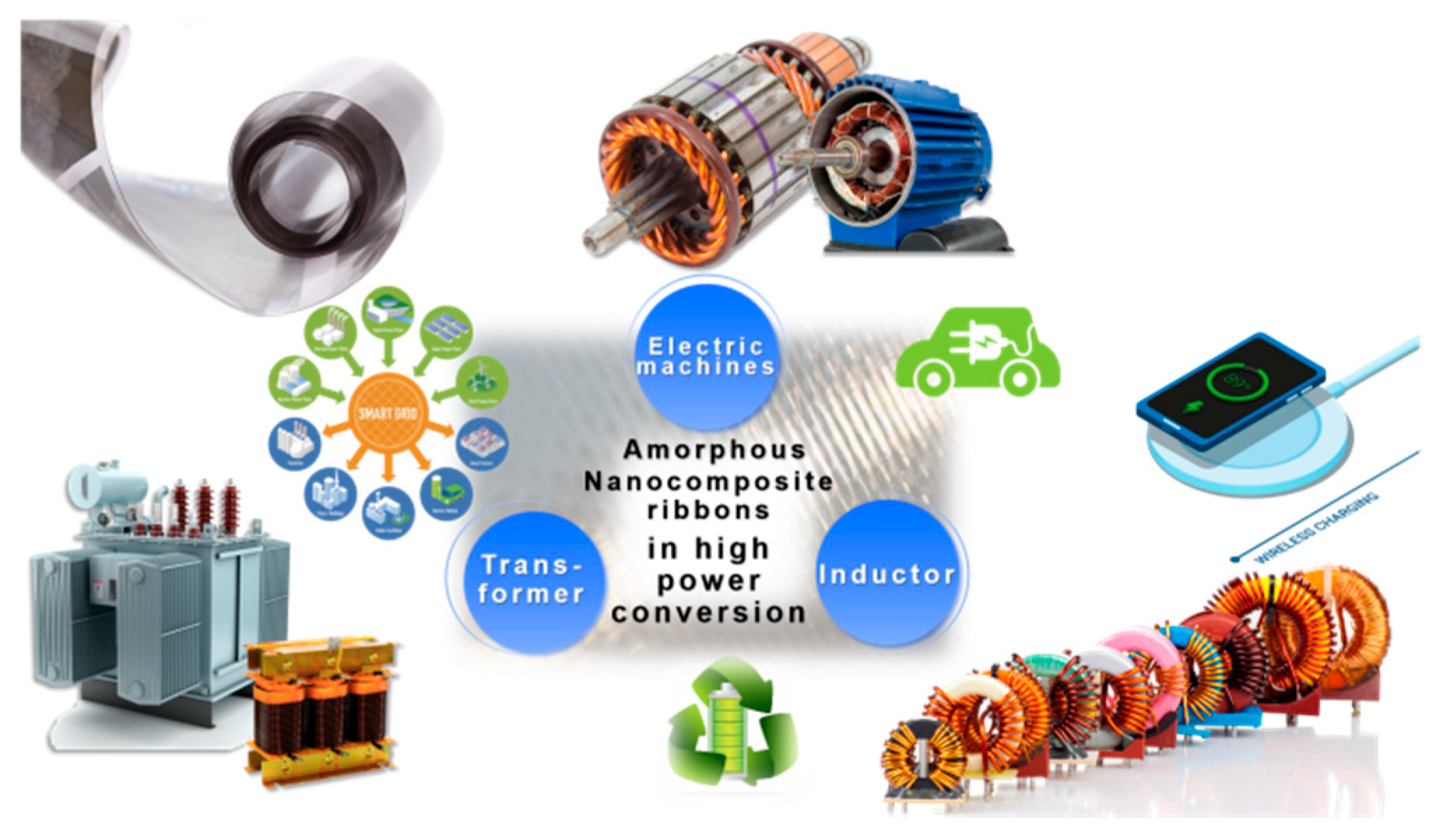
1. Introduction
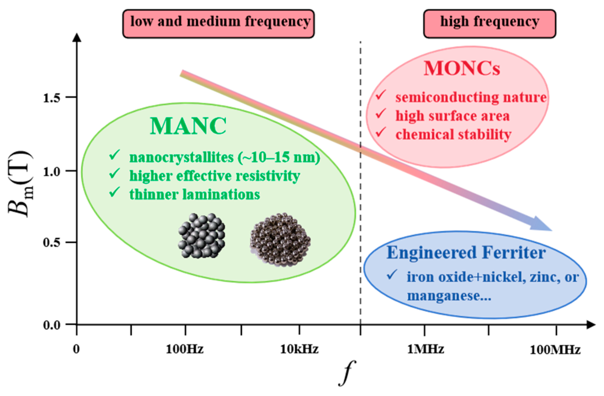
2. An Overview of Soft Magnetic Materials
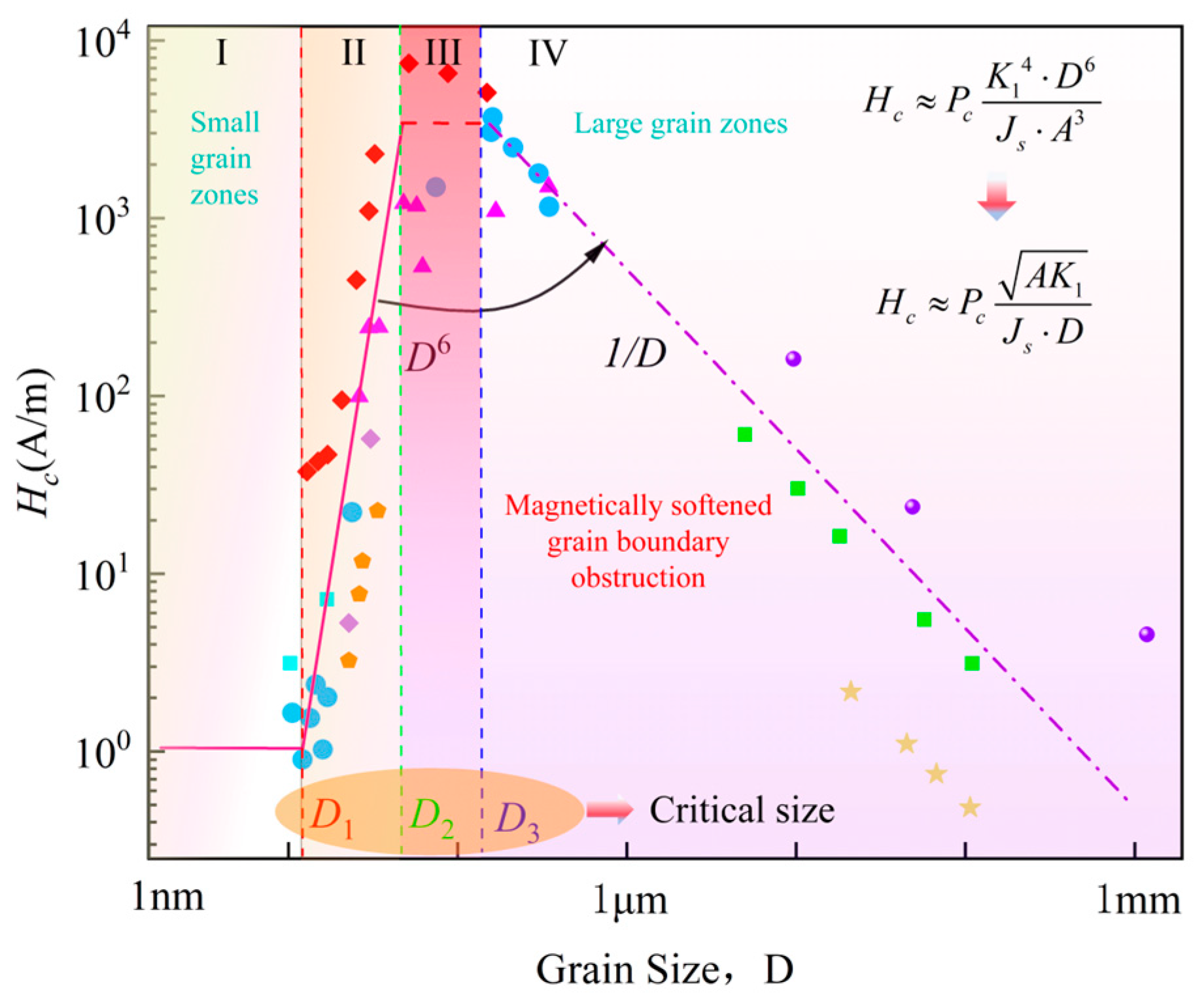
2.1. Magnetic Characteristics
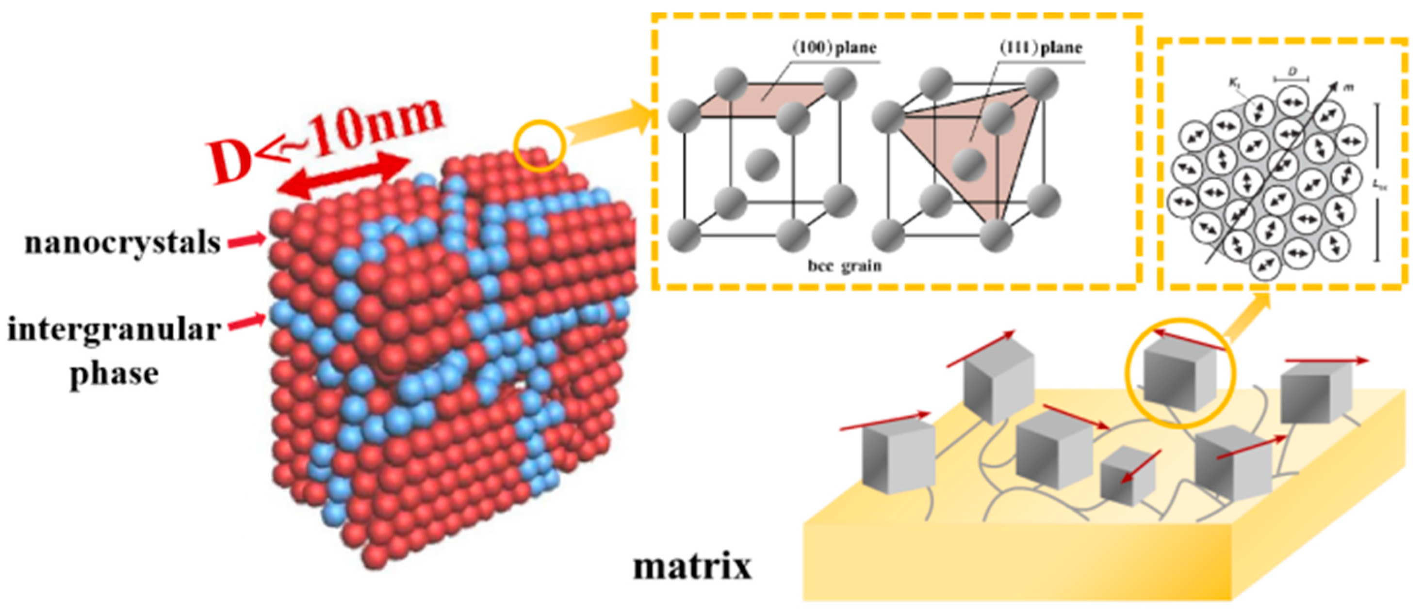
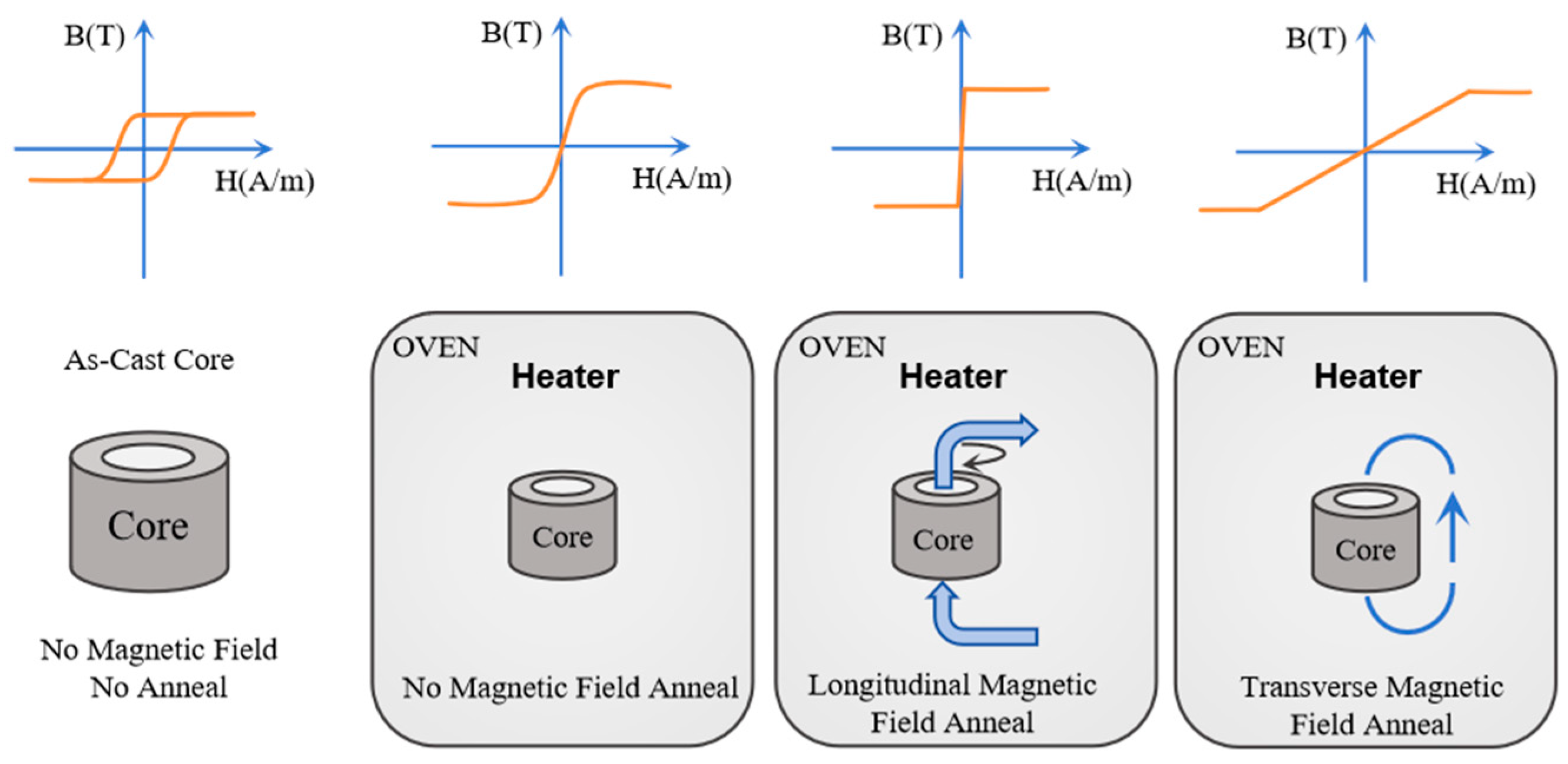
2.2. Material Structure, Magnetism, and Correlation with Heat Treatment and Composition
3. Application in High-Power-Density Transformers
3.1. Requirement and Utilization of Soft Magnetic Materials in Transformers
3.2. Transformer Cores
3.2.1. Amorphous and Nanocrystalline Alloy Core Materials
3.2.2. Principle and Calculation of Magnetic Core Power Loss
3.2.3. Thermal Simulation and Modeling
3.2.4. Insulation and Vibration
4. Application in Power Inductors
4.1. Requirement and Utilization of Soft Magnetic Materials in Inductors
4.2. Configuration of Inductor Cores
4.3. Application in Inductor Cores
4.4. Design and Manufacturing of Power Inductor
4.4.1. Winding Design of Inductors
4.4.2. Vibration and Noise
5. Application in Power Motor
5.1. Amorphous and Nanocrystalline Alloy Requirements
5.2. Performance Analysis of Stator Cores
5.2.1. Vibration and Noise of Stator Cores
5.2.2. Temperature Rise and Cooling
5.3. Design and Manufacturing of Power Motor
6. Concluding Remarks and Prospects
Author Contributions
Funding
Conflicts of Interest
References
- Granata, S.; Di Benedetto, M.; Terlizzi, C.; Leuzzi, R.; Bifaretti, S.; Zanchetta, P. Power Electronics Converters for the Internet of Energy: A Review. Energies 2022, 15, 2604. [Google Scholar] [CrossRef]
- Silveyra, J.M.; Ferrara, E.; Huber, D.L.; Monson, T.C. Soft magnetic materials for a sustainable and electrified world. Science 2018, 362, eaao0195. [Google Scholar] [CrossRef] [PubMed]
- Talaat, A.; Suraj, M.V.; Byerly, K.; Wang, A.; Wang, Y.; Lee, J.K.; Ohodnicki, P.R. Review on soft magnetic metal and inorganic oxide nanocomposites for power applications. J. Alloys Compd. 2021, 870, 159500. [Google Scholar] [CrossRef]
- Balasubramanian, B.; Manchanda, P.; Pahari, R.; Chen, Z.; Zhang, W.Y.; Valloppilly, S.R.; Li, X.Z.; Sarella, A.; Yue, L.P.; Ullah, A.; et al. Chiral Magnetism and High-Temperature Skyrmions in B20-Ordered Co-Si. Phys. Rev. Lett. 2020, 124, 057201. [Google Scholar] [CrossRef]
- Zhang, W.Y.; Balasubramanian, B.; Ullah, A.; Pahari, R.; Li, X.Z.; Yue, L.P.; Valloppilly, S.R.; Sokolov, A.; Skomski, R.; Sellmyer, D.J. Comparative study of topological Hall effect and skyrmions in NiMnIn and NiMnGa. Appl. Phys. Lett. 2019, 115, 172404. [Google Scholar] [CrossRef]
- Mallakpour, S.; Khadem, E. Carbon nanotube-metal oxide nanocomposites: Fabrication, properties and applications. Chem. Eng. J. 2016, 302, 344–367. [Google Scholar] [CrossRef]
- Zhang, Q.H.; Zhou, Z.X.; Dylla, M.; Agne, M.T.; Pei, Y.Z.; Wang, L.J.; Tang, Y.S.; Liao, J.C.; Li, J.; Bai, S.Q.; et al. Realizing high-performance thermoelectric power generation through grain boundary engineering of skutterudite-based nanocomposites. Nano Energy 2017, 41, 501–510. [Google Scholar] [CrossRef]
- Inoue, A.; Zhang, T.; Takeuchi, A. Ferrous and Nonferrous Bulk Amorphous Alloys. Mater. Sci. Forum 1998, 269–272, 855–864. [Google Scholar] [CrossRef]
- Yoshizawa, Y.; Oguma, S.; Yamauchi, K. New Fe-based soft magnetic-alloys composed of ultrafine grain-structure. J. Appl. Phys. 1988, 64, 6044–6046. [Google Scholar] [CrossRef]
- Makino, A. Nanocrystalline Soft Magnetic Fe-Si-B-P-Cu Alloys with High B of 1.8–1.9T Contributable to Energy Saving. IEEE Trans. Magn. 2012, 48, 1331–1335. [Google Scholar] [CrossRef]
- Suzuki, K.; Makino, A.; Inoue, A.; Masumoto, T. Soft magnetic properties of nanocrystalline bcc Fe-Zr-B and Fe-M-B-Cu (M=transition metal) alloys with high saturation magnetization (invited). J. Appl. Phys. 1991, 70, 6232–6237. [Google Scholar] [CrossRef]
- Duwez, P.; Lin, S.C.H. Amorphous Ferromagnetic Phase in Iron-Carbon-Phosphorus Alloys. J. Appl. Phys. 1967, 38, 4096–4097. [Google Scholar] [CrossRef]
- Shokrollahi, H.; Janghorban, K. Soft magnetic composite materials (SMCs). J. Mater. Process. Technol. 2007, 189, 1–12. [Google Scholar] [CrossRef]
- Nogués, J.; Sort, J.; Langlais, V.; Skumryev, V.; Suriñach, S.; Muñoz, J.S.; Baró, M.D. Exchange bias in nanostructures. Phys. Rep. Rev. Sec. Phys. Lett. 2005, 422, 65–117. [Google Scholar] [CrossRef]
- Yamaura, S.; Furuya, Y.; Watanabe, T. The effect of grain boundary microstructure on Barkhausen noise in ferromagnetic materials. Acta Mater. 2001, 49, 3019–3027. [Google Scholar] [CrossRef]
- Herzer, G. Modern soft magnets: Amorphous and nanocrystalline materials. Acta Mater. 2013, 61, 718–734. [Google Scholar] [CrossRef]
- Ullah, A.; Balasubramanian, B.; Tiwari, B.; Giri, B.; Sellmyer, D.J.; Skomski, R.; Xu, X.S. Topological spin textures and topological Hall effect in centrosymmetric magnetic nanoparticles. Phys. Rev. B 2023, 108, 184432. [Google Scholar] [CrossRef]
- Herzer, G. Soft-magnetic nanocrystalline materials. Scr. Metall. Mater. 1995, 33, 1741–1756. [Google Scholar] [CrossRef]
- Xiao, M.; Zheng, Z.G.; Ji, L.; Liu, X.; Qiu, Z.G.; Zeng, D.C. The role of V and Mo on crystallization process and magnetic properties of FeSiBCuNb alloys using in wide frequency scale. J. Non Cryst. Solids 2019, 521, 119546. [Google Scholar] [CrossRef]
- Willard, M.A.; Daniil, M.; Kniping, K.E. Nanocrystalline soft magnetic materials at high temperatures: A perspective. Scr. Mater. 2012, 67, 554–559. [Google Scholar] [CrossRef]
- Herzer, G. Magnetization process in nanocrystalline ferromagnets. Mater. Sci. Eng. A Struct. Mater. Prop. Microstruct. Process. 1991, 133, 1–5. [Google Scholar] [CrossRef]
- Flohrer, S.; Schäfer, R.; McCord, J.; Roth, S.; Schultz, L.; Fiorillo, F.; Günther, W.; Herzer, G. Dynamic magnetization process of nanocrystalline tape wound cores with transverse field-induced anisotropy. Acta Mater. 2006, 54, 4693–4698. [Google Scholar] [CrossRef]
- Kolano, R.; Kolano-Burian, A.; Polak, M.; Szynowski, J. Application of Rapidly Quenched Soft Magnetic Materials in Energy-Saving Electric Equipment. IEEE Trans. Magn. 2014, 50, 2004804. [Google Scholar] [CrossRef]
- Silveyra, J.M.; Xu, P.; Keylin, V.; DeGeorge, V.; Leary, A.; McHenry, M.E. Amorphous and Nanocomposite Materials for Energy-Efficient Electric Motors. J. Electron. Mater. 2016, 45, 219–225. [Google Scholar] [CrossRef]
- Pfützner, H.; Shilyashki, G.; Christodoulou, N. Standardisation concept for rapid testing of effects of cutting on losses of electric steel and amorphous ribbon. IET Electr. Power Appl. 2024, 18, 1164–1173. [Google Scholar] [CrossRef]
- Theisen, E.A. Recent Advances and Remaining Challenges in Manufacturing of Amorphous and Nanocrystalline Alloys. IEEE Trans. Magn. 2022, 58, 2001207. [Google Scholar] [CrossRef]
- Jin, J.X.; Tang, Y.J.; Xiao, X.Y.; Du, B.X.; Wang, Q.L.; Wang, J.H.; Wang, S.H.; Bi, Y.F.; Zhu, J.G. HTS Power Devices and Systems: Principles, Characteristics, Performance, and Efficiency. IEEE Trans. Appl. Supercond. 2016, 26, 3800526. [Google Scholar] [CrossRef]
- Shadfar, H.; Pashakolaei, M.G.; Foroud, A.A. Solid-state transformers: An overview of the concept, topology, and its applications in the smart grid. Int. Trans. Electr. Energy Syst. 2021, 31, e12996. [Google Scholar] [CrossRef]
- Islam, M.R.; Lei, G.; Guo, Y.G.; Zhu, J.G. Optimal Design of High-Frequency Magnetic Links for Power Converters Used in Grid-Connected Renewable Energy Systems. IEEE Trans. Magn. 2014, 50, 2006204. [Google Scholar] [CrossRef]
- Islam, M.R.; Mahfuz-Ur-Rahman, A.M.; Islam, M.M.; Guo, Y.G.G.; Zhu, J.G.G. Modular Medium-Voltage Grid-Connected Converter with Improved Switching Techniques for Solar Photovoltaic Systems. IEEE Trans. Ind. Electron. 2017, 64, 8887–8896. [Google Scholar] [CrossRef]
- Li, Z.; Han, W.; Xin, Z.; Liu, Q.; Chen, J.; Loh, P.C. A Review of Magnetic Core Materials, Core Loss Modeling and Measurements in High-Power High-Frequency Transformers. CPSS Trans. Power Electron. Appl. 2022, 7, 359–373. [Google Scholar] [CrossRef]
- Liu, J.; Mei, Y.; Lu, G. Development of High-frequency Soft Magnetic Materials for Power Electronics. J. Mater. Eng. 2017, 45, 127–134. [Google Scholar]
- Bashir-U-Din, A. Characterisation of Amorphous Metal Materials for High-Frequency High-Power-Density Transformer. In Proceedings of the 26th International Conference on Systems Engineering (ICSEng), University of Technology Sydney, Sydney, Australia, 18–20 December 2018. [Google Scholar]
- Leary, A.M.; Ohodnicki, P.R.; McHenry, M.E. Soft Magnetic Materials in High-Frequency, High-Power Conversion Applications. JOM 2012, 64, 772–781. [Google Scholar] [CrossRef]
- Islam, M.R.; Muttaqi, K.M.; Sutanto, D.; Zhu, J.G. Design and Implementation of Amorphous Magnetic Material Common Magnetic Bus for the Replacement of Common DC Bus. IEEE Trans. Magn. 2018, 54, 2002004. [Google Scholar] [CrossRef]
- VK GmbH & Co. Properties of Amorphous Co-Based Alloys with F-Characteristics. Available online: https://www.vacuumschmelze.com/products (accessed on 30 November 2024).
- Ohta, M.; Hasegawa, R. Soft Magnetic Properties of Magnetic Cores Assembled with a High Bs Fe-Based Nanocrystalline Alloy. IEEE Trans. Magn. 2017, 53, 2000205. [Google Scholar] [CrossRef]
- Ohta, M.; Hasegawa, R.; Itabashi, H. Development of Block Cores Comprising High-Bs Nanocrystalline Alloy Ribbon. IEEE Trans. Magn. 2018, 54, 2000504. [Google Scholar] [CrossRef]
- Yoshizawa, Y.; Ohta, M. Magnetic properties of nanocrystalline Fe-Cu-Si-B alloys. In Proceedings of the 13th International Conference on Rapidly Quenched and Metastable Materials, Dresden, Germany, 24–29 August 2008. [Google Scholar]
- Makino, A.; Men, H.; Kubota, T.; Yubuta, K.; Inoue, A. FeSiBPCu Nanocrystalline Soft Magnetic Alloys with High Bs of 1.9 Tesla Produced by Crystallizing Hetero-Amorphous Phase. Mater. Trans. 2009, 50, 204–209. [Google Scholar] [CrossRef]
- Ruiz-Robles, D.; Figueroa-Barrera, C.; Moreno-Goytia, E.L.; Venegas-Rebollar, V. An Experimental Comparison of the Effects of Nanocrystalline Core Geometry on the Performance and Dispersion Inductance of the MFTs Applied in DC-DC Converters. Electronics 2020, 9, 453. [Google Scholar] [CrossRef]
- Azuma, D.; Ito, N.; Ohta, M. Recent progress in Fe-based amorphous and nanocrystalline soft magnetic materials. J. Magn. Magn. Mater. 2020, 501, 166373. [Google Scholar] [CrossRef]
- Francoeur, B.; Couture, P. Continuous-annealing method for producing a flexible, curved, soft magnetic amorphous alloy ribbon. J. Appl. Phys. 2012, 111, 07A309. [Google Scholar] [CrossRef]
- Lin, K.C.; Zook, E.E.; Crockett, J.W. Material usage in stacked transformer cores. J. Mater. Eng. 1990, 12, 51–57. [Google Scholar] [CrossRef]
- Fukunaga, H.; Eguchi, T.; Koga, K.; Ohta, Y.; Kakehashi, H. High-performance cut cores prepared from crystallized Fe-based amorphous ribbon. IEEE Trans. Magn. 1990, 26, 2008–2010. [Google Scholar] [CrossRef]
- Imaoka, J.; Okamoto, K.; Shoyama, M.; Ishikura, Y.; Noah, M.; Yamamoto, M. Modeling, Magnetic Design, Simulation Methods, and Experimental Evaluation of Various Powder Cores Used in Power Converters Considering Their DC Superimposition Characteristics. IEEE Trans. Power Electron. 2019, 34, 9033–9051. [Google Scholar] [CrossRef]
- Lakatos-Varsányi, M.; Mikó, A.; Varga, L.K.; Kálmán, E. Electrodeposited magnetic multi-nano-layers. Corros. Sci. 2005, 47, 681–693. [Google Scholar] [CrossRef]
- Varga, L.K. Soft magnetic nanocomposites for high-frequency and high-temperature applications. J. Magn. Magn. Mater. 2007, 316, 442–447. [Google Scholar] [CrossRef]
- Fujimori, H.; Ohnuma, S.; Kobayashi, N.; Masumoto, T. Spintronics in metal-insulator nanogranular magnetic thin films. J. Magn. Magn. Mater. 2006, 304, 32–35. [Google Scholar] [CrossRef]
- Ohnuma, S.; Ohnuma, M.; Fujimori, H.; Masumoto, T. Metal-insulator type nano-granular soft magnetic thin films investigations on mechanism and applications. J. Magn. Magn. Mater. 2007, 310, 2503–2509. [Google Scholar] [CrossRef]
- Naoe, M.; Sonehara, M.; Miyaji, K.; Sato, T.; Endo, Y.; Kobayashi, N.; Arai, K.I. Crossed anisotropy multilayered nanogranular films combining high permeability, ferromagnetic resonance frequency, and resistivity. In Proceedings of the 2023 IEEE International Magnetic Conference-Short Papers (INTERMAG Short Papers), Sendai, Japan, 15–19 May 2023; pp. 1–2. [Google Scholar] [CrossRef]
- Luo, Z.C.; Li, X.R.; Jiang, C.Q.; Long, T. Characterization of Nanocrystalline Flake Ribbon for High Frequency Magnetic Cores. IEEE Trans. Power Electron. 2022, 37, 14011–14016. [Google Scholar] [CrossRef]
- Bertotti, G. General-properties of power losses in soft ferromagnetic materials. IEEE Trans. Magn. 1988, 24, 621–630. [Google Scholar] [CrossRef]
- Liu, F.-g.; Zhao, L.; Jiang, J.-c. Calculation and verification of core loss of high frequency transformer under sinusoidal and non-sinusoidal excitation. Adv. Technol. Electr. Eng. Energy 2021, 40, 25–32. [Google Scholar] [CrossRef]
- Li, C.; Xu, Q. Modeling of Temperature Dependent Hysteresis Based on Preisach Theory. Trans. China Electrotech. Soc. 2013, 28, 90–94. [Google Scholar]
- Shi, Y.M.; Jiles, D.C.; Ramesh, A. Generalization of hysteresis modeling to anisotropic and textured materials. J. Magn. Magn. Mater. 1998, 187, 75–78. [Google Scholar] [CrossRef]
- Sablik, M.J.; Jiles, D.C. Coupled magnetoelastic theory of magnetic and magnetostrictive hysteresis. IEEE Trans. Magn. 1993, 29, 2113–2123. [Google Scholar] [CrossRef]
- Raghunathan, A.; Melikhov, Y.; Snyder, J.E.; Jiles, D.C. Modeling the Temperature Dependence of Hysteresis Based on Jiles-Atherton Theory. IEEE Trans. Magn. 2009, 45, 3954–3957. [Google Scholar] [CrossRef]
- Gao, Y.H.; Araki, Y.; Dozono, H.; Muramatsu, K.; Guan, W.M.; Yuan, J.X.; Tian, C.H.; Chen, B.C. Modeling of Anomalous Eddy Current Losses Due to Movement of Domain Walls in Particles of a Soft Magnetic Composite. IEEE Trans. Magn. 2020, 56, 7515904. [Google Scholar] [CrossRef]
- Pry, R.H.; Bean, C.P. Calculation of The Energy Loss in Magnetic Sheet Materials Using a Domain Model. J. Appl. Phys. 1958, 29, 532–533. [Google Scholar] [CrossRef]
- Mayergoyz, I.D. Mathematical-models of hysteresis. IEEE Trans. Magn. 1986, 22, 603–608. [Google Scholar] [CrossRef]
- Adly, A.A.; Mayergoyz, I.D.; Bergqvist, A. Preisach modeling of magnetostrictive hysteresis. J. Appl. Phys. 1991, 69, 5777–5779. [Google Scholar] [CrossRef]
- Stoner, E.C.; Wohlfarth, E.P. A mechanism of magnetic hysteresis in heterogeneous alloys. Philos. Trans. R. Soc. Lond. Ser. A Math. Phys. Sci. 1948, 240, 599–642. [Google Scholar] [CrossRef]
- Jiles, D.C.; Atherton, D.L. Theory of ferromagnetic hysteresis. J. Appl. Phys. 1984, 55, 2115–2120. [Google Scholar] [CrossRef]
- Venkatachalam, K.; Sullivan, C.R.; Abdallah, T.; Tacca, H. Accurate prediction of ferrite core loss with nonsinusoidal waveforms using only Steinmetz parameters. In Proceedings of the 8th Workshop on Computers in Power Electronics, University of Puerto Rico, Mayaguez, Puerto Rico, 3–4 June 2002; pp. 36–41. [Google Scholar]
- Van den Bossche, A.; Valchev, V.C.; Georgiev, G.B. Measurement and loss model of ferrites with non-sinusoidal waveforms. In Proceedings of the 35th Annual IEEE Power Electronics Specialists Conference (PESC 04), Aachen, Germany, 20–25 June 2004; pp. 4814–4818. [Google Scholar]
- Shen, W.; Wang, F.; Boroyevich, D.; Tipton, C.W. Loss characterization and calculation of nanocrystalline cores for high-frequency magnetics applications. In Proceedings of the 22nd Annual IEEE Applied Power Electronics Conference (APEC 2007), Anaheim, CA, USA, 25 February–1 March 2007; pp. 475–484. [Google Scholar]
- Reinert, J.; Brockmeyer, A.; De Doncker, R.W. Calculation of losses in ferro- and ferrimagnetic materials based on the modified Steinmetz equation. In Proceedings of the Conference Record of the 1999 IEEE Industry Applications Conference. Thirty-Forth IAS Annual Meeting (Cat. No.99CH36370), Phoenix, AZ, USA, 3–7 October 1999; Volume 2083, pp. 2087–2092. [Google Scholar] [CrossRef]
- Li, J.L.; Abdallah, T.; Sullivan, C.R. Improved calculation of core loss with nonsinusoidal waveforms. In Proceedings of the 36th Annual Meeting of the Industry-Application-Society (IAS), Chicago, IL, USA, 30 September–4 October 2000; pp. 2203–2210. [Google Scholar]
- He, S.; Yongjian, L.; Xinran, Y.; Shuaichao, Y.; Ming, Y. Research of Harmonic Effects on Core Loss in Soft Magnetic Composite Materials Based on Three-Dimensional Magnetic Test System. In Proceedings of the 2019 22nd International Conference on Electrical Machines and Systems (ICEMS), Harbin, China, 11–14 August 2019; pp. 1–5. [Google Scholar] [CrossRef]
- Villar, I.; Viscarret, U.; Etxeberria-Otadui, I.; Rufer, A. Global Loss Evaluation Methods for Nonsinusoidally Fed Medium-Frequency Power Transformers. IEEE Trans. Ind. Electron. 2009, 56, 4132–4140. [Google Scholar] [CrossRef]
- Mühlethaler, J.; Biela, J.; Kolar, J.W.; Ecklebe, A. Improved Core-Loss Calculation for Magnetic Components Employed in Power Electronic Systems. IEEE Trans. Power Electron. 2012, 27, 964–973. [Google Scholar] [CrossRef]
- Barg, S.; Ammous, K.; Mejbri, H.; Ammous, A. An Improved Empirical Formulation for Magnetic Core Losses Estimation Under Nonsinusoidal Induction. IEEE Trans. Power Electron. 2017, 32, 2146–2154. [Google Scholar] [CrossRef]
- Zhao, H.Y.; Ragusa, C.; Appino, C.; de la Barrière, O.; Wang, Y.H.; Fiorillo, F. Energy Losses in Soft Magnetic Materials Under Symmetric and Asymmetric Induction Waveforms. IEEE Trans. Power Electron. 2019, 34, 2655–2665. [Google Scholar] [CrossRef]
- Ahn, H.M.; Oh, Y.H.; Kim, J.K.; Song, J.S.; Hahn, S.C. Experimental Verification and Finite Element Analysis of Short-Circuit Electromagnetic Force for Dry-Type Transformer. IEEE Trans. Magn. 2012, 48, 819–822. [Google Scholar] [CrossRef]
- Wu, W.; Kern, J.A. Temperature rise prediction of a natural cooling dry-type transformer. In Proceedings of the SoutheastCon 2016, Norfolk, VA, USA, 30 March–3 April 2016. [Google Scholar]
- Lee, M.; Abdullah, H.A.; Jofriet, J.C.; Patel, D. Temperature distribution in foil winding for ventilated dry-type power transformers. Electr. Power Syst. Res. 2010, 80, 1065–1073. [Google Scholar] [CrossRef]
- Smolka, J.; Nowak, A.J. Shape Optimization of Coils and Cooling Ducts in Dry-Type Transformers Using Computational Fluid Dynamics and Genetic Algorithm. IEEE Trans. Magn. 2011, 47, 1726–1731. [Google Scholar] [CrossRef]
- Liu, C.; Ruan, J.J.; Wen, W.; Gong, R.H.; Liao, C.B. Temperature rise of a dry-type transformer with quasi-3D coupled-field method. IET Electr. Power Appl. 2016, 10, 598–603. [Google Scholar] [CrossRef]
- Finocchio, M.A.F.; Lopes, J.J.; de França, J.A.; Piai, J.C.; Mangili, J.F. Neural networks applied to the design of dry-type transformers: An example to analyze the winding temperature and elevate the thermal quality. Int. Trans. Electr. Energy Syst. 2017, 27, e2257. [Google Scholar] [CrossRef]
- Chen, Y.F.; Yang, Q.X.; Zhang, C.G.; Li, Y.J.; Li, X.H. Thermal Network Model of High-Power Dry-Type Transformer Coupled with Electromagnetic Loss. IEEE Trans. Magn. 2022, 58, 8402105. [Google Scholar] [CrossRef]
- Yan, X.X.; Li, Y.J.; Cheng, Z.G.; Zhang, C.G. Prediction of temperature rise for ventilated dry-type transformer by 3-D coupled magneto-fluid-thermal model. Int. J. Appl. Electromagn. Mech. 2020, 62, 725–735. [Google Scholar] [CrossRef]
- Sun, Y.Y.; Xu, G.D.; Li, N.; Li, K.J.; Liang, Y.L.; Zhong, H.; Zhang, L.N.; Liu, P. Hotspot Temperature Prediction of Dry-Type Transformers Based on Particle Filter Optimization with Support Vector Regression. Symmetry 2021, 13, 1320. [Google Scholar] [CrossRef]
- Zhao, S.S.; Li, Q.; Lee, F.C. High Frequency Transformer Design for Modular Power Conversion from Medium Voltage AC to 400V DC. In Proceedings of the 32nd Annual IEEE Applied Power Electronics Specialists Conference and Exposition (APEC), Tampa, FL, USA, 26–30 March 2017; pp. 2894–2901. [Google Scholar]
- Shuai, P.; Biela, J. Influence of Material Properties and Geometric Shape of Magnetic Cores on Acoustic Noise Emission of Medium-Frequency Transformers. IEEE Trans. Power Electron. 2017, 32, 7916–7931. [Google Scholar] [CrossRef]
- Zhang, F.; Ji, S.C.; Shi, Y.H.; Zhu, L.Y. Investigation on the Action of Eddy Current on Tank Vibration Characteristics in Dry-Type Transformer. IEEE Trans. Magn. 2019, 55, 8400908. [Google Scholar] [CrossRef]
- Moses, A.J.; Anderson, P.I.; Phophongviwat, T.; Tabrizi, S. Contribution of magnetostriction to transformer noise. In Proceedings of the 2010 45th International Universities Power Engineering Conference (UPEC 2010), Cardiff, UK, 31 August–3 September 2010; pp. 1–5. [Google Scholar]
- Belahcen, A. Magnetoelasticity, Magnetic Forces and Magnetostriction in Electrical Machines; Helsinki University of Technology: Helsinki, Finland, 2004. [Google Scholar]
- Weiser, B.; Pfützner, H.; Anger, J. Relevance of magnetostriction and forces for the generation of audible noise of transformer cores. IEEE Trans. Magn. 2000, 36, 3759–3777. [Google Scholar] [CrossRef]
- Li, J.; Water, W.; Zhu, B.Y.; Lu, J.W. Integrated High-Frequency Coaxial Transformer Design Platform Using Artificial Neural Network Optimization and FEM Simulation. IEEE Trans. Magn. 2015, 51, 8500204. [Google Scholar] [CrossRef]
- Ruiz-Robles, D.; Venegas-Rebollar, V.; Anaya-Ruiz, A.; Moreno-Goytia, E.L.; Rodríguez-Rodríguez, J.R. Design and Prototyping Medium-Frequency Transformers Featuring a Nanocrystalline Core for DC-DC Converters. Energies 2018, 11, 2081. [Google Scholar] [CrossRef]
- Guo, Z.C.; Rajendran, S.; Tangudu, J.; Khakpour, Y.; Taylor, S.; Xing, L.; Xu, Y.; Feng, X.Y.; Huang, A.Q. A Novel High Insulation 100 kW Medium Frequency Transformer. IEEE Trans. Power Electron. 2023, 38, 112–117. [Google Scholar] [CrossRef]
- Battal, F.; Balci, S.; Sefa, I. An Analysis of High Power Inductor Vibration Behavior in Terms of Air Gaps. In Proceedings of the 2019 International Conference on Power Generation Systems and Renewable Energy Technologies (PGSRET), Istanbul, Turkey, 26–27 August 2019; pp. 1–6. [Google Scholar] [CrossRef]
- Jiang, C.Q.; Li, X.R.; Ghosh, S.S.; Zhao, H.; Shen, Y.F.; Long, T. Nanocrystalline Powder Cores for High-Power High-Frequency Power Electronics Applications. IEEE Trans. Power Electron. 2020, 35, 10821–10830. [Google Scholar] [CrossRef]
- Yeo, J.G.; Kim, D.H.; Choi, Y.J.; Lee, B.W. Improving Power-Inductor Performance by Mixing Sub-micro Fe Powder with Amorphous Soft Magnetic Composites. J. Electron. Mater. 2019, 48, 6018–6023. [Google Scholar] [CrossRef]
- Lara-Reyes, J.; Ponce-Silva, M.; Cortés-García, C.; Lozoya-Ponce, R.E.; Parrilla-Rubio, S.M.; García-García, A.R. High-Power-Factor LC Series Resonant Converter Operating Off-Resonance with Inductors Elaborated with a Composed Material of Resin/Iron Powder. Electronics 2022, 11, 3761. [Google Scholar] [CrossRef]
- Soinski, M.; Leszczynski, J.; Swieboda, C.; Kwiecien, M. Nanocrystalline Block Cores for High-Frequency Chokes. IEEE Trans. Magn. 2014, 50, 2801904. [Google Scholar] [CrossRef]
- Yan, Y.K.; Geng, L.W.D.; Zhang, L.J.; Tu, C.; Sriramdas, R.; Liu, H.R.; Li, X.T.; Sanghadasa, M.; Ngo, K.D.T.; Wang, Y.U.; et al. High-Power Magnetoelectric Voltage Tunable Inductors. IEEE Trans. Ind. Electron. 2021, 68, 5355–5365. [Google Scholar] [CrossRef]
- Soinski, M.; Leszczynski, J.; Swieboda, C.; Kwiecien, M. The applicability of nanocrystalline stacked cores for power electronics. Int. J. Appl. Electromagn. Mech. 2015, 48, 301–307. [Google Scholar] [CrossRef]
- Yang, R.S.; Hanson, A.J.; Perreault, D.J.; Sullivan, C.R. A Low-Loss Inductor Structure and Design Guidelines for High-Frequency Applications. In Proceedings of the 33rd Annual IEEE Applied Power Electronics Conference and Exposition (APEC), San Antonio, TX, USA, 4–8 March 2018; pp. 579–586. [Google Scholar]
- Varga, L.K. High-Frequency Inductor Materials. J. Electron. Mater. 2014, 43, 117–120. [Google Scholar] [CrossRef]
- Mao, X.; Chen, W. Winding loss mechanism analysis and the design for a new structure high-frequency gapped inductor. In Proceedings of the INTERMAG Asia 2005: Digest of the IEEE International Magnetics Conference (IEEE Cat. No.05CH37655), Nagoya, Japan, 4–8 April 2005; pp. 1073–1074. [Google Scholar] [CrossRef]
- Neumayr, D.; Bortis, D.; Kolar, J.W.; Hoffmann, S.; Hoene, E. Origin and quantification of increased core loss in MnZn ferrite plates of a multi-gap inductor. CPSS Trans. Power Electron. Appl. 2019, 4, 72–93. [Google Scholar] [CrossRef]
- Zhao, H.B.; Huang, Z.Z.; Dalal, D.N.; Jorgensen, J.K.; Jorgensen, A.B.; Wang, X.F.; Munk-Nielsen, S. Parasitic Capacitance Modeling of Copper-Foiled Medium-Voltage Filter Inductors Considering Fringe Electrical Field. IEEE Trans. Power Electron. 2021, 36, 8181–8192. [Google Scholar] [CrossRef]
- Lai, Y.W.; Wang, S.; Zhang, B.Y. Investigation of Magnetic Field Immunity and Near Magnetic Field Reduction for the Inductors in High Power Density Design. IEEE Trans. Power Electron. 2019, 34, 5340–5351. [Google Scholar] [CrossRef]
- Rossi, M.; Le Besnerais, J. Vibration Reduction of Inductors Under Magnetostrictive and Maxwell Forces Excitation. IEEE Trans. Magn. 2015, 51, 8403406. [Google Scholar] [CrossRef]
- Du, B.X.; Liu, D.S. Dynamic Behavior of Magnetostriction-Induced Vibration and Noise of Amorphous Alloy Cores. IEEE Trans. Magn. 2015, 51, 7208708. [Google Scholar] [CrossRef]
- Yoo, K.Y.; Lee, B.K.; Kim, D.H. Investigation of Vibration and Acoustic Noise Emission of Powder Core Inductors. IEEE Trans. Power Electron. 2019, 34, 3633–3645. [Google Scholar] [CrossRef]
- Cuellar, C.; Benabou, A.; Idir, N. Characterization and Modeling of Hysteresis for Magnetic Materials Used in EMI Filters of Power Converters. IEEE Trans. Power Electron. 2014, 29, 4911–4920. [Google Scholar] [CrossRef]
- Kovacic, M.; Hanic, Z.; Stipetic, S.; Krishnamurthy, S.; Zarko, D. Analytical Wideband Model of a Common-Mode Choke. IEEE Trans. Power Electron. 2012, 27, 3173–3185. [Google Scholar] [CrossRef]
- Caponet, M.C.; Profumo, F.; Tenconi, A. EMI filters design for power electronics. In Proceedings of the 33rd IEEE Annual Power Electronics Specialists Conference (PESC02), Cairns, Australia, 23–27 June 2002; pp. 2027–2032. [Google Scholar]
- Liu, Y.Z.; Ou, J.; Schiefer, M.; Breining, P.; Grilli, F.; Doppelbauer, M. Application of an Amorphous Core to an Ultra-High-Speed Sleeve-Free Interior Permanent-Magnet Rotor. IEEE Trans. Ind. Electron. 2018, 65, 8498–8509. [Google Scholar] [CrossRef]
- Ismagilov, F.R.; Papini, L.; Vavilov, V.E.; Gusakov, D.V. Design and Performance of a High-Speed Permanent Magnet Generator with Amorphous Alloy Magnetic Core for Aerospace Applications. IEEE Trans. Ind. Electron. 2020, 67, 1750–1758. [Google Scholar] [CrossRef]
- Celie, J.; Stie, M.; Rens, J.; Sergeant, P. Effects of cutting and annealing of amorphous materials for high speed permanent magnet machines. In Proceedings of the 22nd International Conference on Electrical Machines (ICEM), Lausanne, Switzerland, 4–7 September 2016; pp. 1630–1635. [Google Scholar]
- Enomoto, Y.; Ito, M.; Koharagi, H.; Masaki, R.; Ohiwa, S.; Ishihara, C.; Mita, A. Evaluation of experimental permanent-magnet brushless motor utilizing new magnetic material for stator core teeth. IEEE Trans. Magn. 2005, 41, 4304–4308. [Google Scholar] [CrossRef]
- Mischler, W.R.; Rosenberry, G.M.; Frischmann, P.G.; Tompkins, R.E. Test-Results on a Low-Loss Amorphous Iron Induction-Motor. IEEE Trans. Power Appar. Syst. 1981, 100, 2907–2911. [Google Scholar] [CrossRef]
- Johnson, L.A.; Cornell, E.P.; Bailey, D.J.; Hegyi, S.M. Application of Low-Loss Amorphous Metals in Motors and Transformers. IEEE Trans. Power Appar. Syst. 1982, 101, 2109–2114. [Google Scholar] [CrossRef]
- Jensen, C.C.; Profumo, F.; Lipo, T.A. A low loss permanent magnet brushless DC motor utilizing tape wound amorphous iron. In Proceedings of the Conference Record of the 1990 IEEE Industry Applications Society Annual Meeting (Cat. No.90CH2935-5), Seattle, WA, USA, 7–12 October 1990; Volume 281, pp. 281–286. [Google Scholar] [CrossRef]
- Liew, G.S.; Ertugrul, N.; Wen Liang, S.; Gayler, J. Investigation of axial field permanent magnet motor utilising amorphous magnetic material. Aust. J. Electr. Electron. Eng. 2007, 3, 111–120. [Google Scholar] [CrossRef]
- Wang, Z.; Masaki, R.; Morinaga, S.; Enomoto, Y.; Itabashi, H.; Ito, M.; Tanigawa, S. Development of an Axial Gap Motor with Amorphous Metal Cores. IEEE Trans. Ind. Appl. 2011, 47, 1293–1299. [Google Scholar] [CrossRef]
- Fan, Z.Y.; Yi, H.; Xu, J.; Xie, K.; Qi, Y.; Ren, S.L.; Wang, H.D. Performance Study and Optimization Design of High-Speed Amorphous Alloy Induction Motor. Energies 2021, 14, 2468. [Google Scholar] [CrossRef]
- Makino, A.; Hatanai, T.; Inoue, A.; Masumoto, T. Nanocrystalline soft magnetic Fe-M-B (M=Zr, Hf, Nb) alloys and their applications. Mater. Sci. Eng. A Struct. Mater. Prop. Microstruct. Process. 1997, 226, 594–602. [Google Scholar] [CrossRef]
- Moses, A.J. Energy efficient electrical steels: Magnetic performance prediction and optimization. Scr. Mater. 2012, 67, 560–565. [Google Scholar] [CrossRef]
- Rom, C.L.; Smaha, R.W.; O’Donnell, S.; Dugu, S.; Bauers, S.R. Emerging magnetic materials for electric vehicle drive motors. MRS Bull. 2024, 49, 738–750. [Google Scholar] [CrossRef]
- Grigorian, C.M.; Rupert, T.J. Multi-principal element grain boundaries: Stabilizing nanocrystalline grains with thick amorphous complexions. J. Mater. Res. 2022, 37, 554–566. [Google Scholar] [CrossRef]
- Chen, G.; Tu, G.; Lv, W. Applications of amorphous/nanocrystalline soft magnetic materials in high efficient motors. J. Magn. Mater. Devics 2012, 43, 1. [Google Scholar]
- Li, S.H.; Li, L.J.; Jia, C.B.; Li, D.R.; Lu, Z.C. Study on Amorphous and Nanocrystalline Stator Cores for High-Speed Motor. Small Spec. Electr. Mach. 2019, 47, 9–12. [Google Scholar]
- Jack, A.G.; Mecrow, B.C.; Dickinson, P.G.; Stephenson, D.; Burdess, J.S.; Fawcett, N.; Evans, J.T. Permanent-magnet machines with powdered iron cores and prepressed windings. IEEE Trans. Ind. Appl. 2000, 36, 1077–1084. [Google Scholar] [CrossRef]
- Cai, Y.; El-faouri, F.S.; Saikawa, N.; Chiba, A. Measurement of Vibration and Acoustic Noise Generated by Magnetostriction in Three Stator Cores Made of High Silicon Steel, Amorphous Iron, and Conventional Silicon Steel. In Proceedings of the 2022 IEEE Energy Conversion Congress and Exposition (ECCE), Detroit, MI, USA, 9–13 October 2022; pp. 1–7. [Google Scholar] [CrossRef]
- Sousa, K.M.; Dreyer, U.J.; Martelli, C.; da Silva, J.C.C. Dynamic Eccentricity Induced in Induction Motor Detected by Optical Fiber Bragg Grating Strain Sensors. IEEE Sens. J. 2016, 16, 4786–4792. [Google Scholar] [CrossRef]
- McCloskey, A.; Arrasate, X.; Hernández, X.; Gómez, I.; Almandoz, G. Analytical calculation of vibrations of electromagnetic origin in electrical machines. Mech. Syst. Signal Proc. 2018, 98, 557–569. [Google Scholar] [CrossRef]
- Xu, X.P.; Han, Q.K.; Qin, Z.Y.; Chu, F.L. Analytical methods for the radial electromagnetic vibration of stator in permanent magnet motors with an amorphous alloy core. Mech. Syst. Signal Proc. 2020, 145, 106909. [Google Scholar] [CrossRef]
- Liu, R.; Zhu, J.; Cao, J. Temperature field analysis of silicon steel and amorphous on permanent magnet synchronous motors used in electrical vehicles. J. Beijing Jiaotong Univ. 2019, 43, 119–125. [Google Scholar]
- Bousbaine, A.; McCormick, M.; Low, W.F. In-situ determination of thermal coefficients for electrical machines. IEEE Trans. Energy Convers. 1995, 10, 385–391. [Google Scholar] [CrossRef]
- Sun, M.; Tang, R.; Han, X.; Tong, W. Temperature field analysis of a high frequency amorphous alloy axial flux permanent magnet machine with different cooling schemes. Electr. Mach. Control 2018, 22, 54–61. [Google Scholar]
- Simizu, S.; Ohodnicki, P.R.; McHenry, M.E. Metal Amorphous Nanocomposite Soft Magnetic Material-Enabled High Power Density, Rare Earth Free Rotational Machines. IEEE Trans. Magn. 2018, 54, 8202505. [Google Scholar] [CrossRef]
- Zaid, M.M.; Ahmad, H.; Sami, I.; Waheed, A.; Hussain Bukhari, S.S.; Ro, J.S. Design of a High Torque Density Interior Permanent Magnet Synchronous Machine with improved Efficiency using Amorphous Magnetic Material. In Proceedings of the 2021 IEEE International Magnetic Conference (INTERMAG), Lyon, France, 26–30 April 2021; pp. 1–4. [Google Scholar] [CrossRef]
- Zhou, J.; Xiao, X. An Advanced High-Speed Permanent Magnet Synchronous Machine Utilizing Amorphous Alloy Core with Unequal Tooth Width. In Proceedings of the 2021 IEEE Sustainable Power and Energy Conference (iSPEC), Nanjing, China, 23–25 December 2021; pp. 3423–3427. [Google Scholar] [CrossRef]
- Ismagilov, F.R.; Vavilov, V.E.; Gusakov, D.V.; Jing, O. High-speed generator with tooth-coil winding, permanent magnets and new design of a stator magnetic core made from amorphous alloy. In Proceedings of the 2018 25th International Workshop on Electric Drives: Optimization in Control of Electric Drives (IWED), Moscow, Russia, 31 January–2 February 2018; pp. 1–5. [Google Scholar] [CrossRef]
- Wu, S.N.; Wang, Y.K.; Tong, W.M. Design and Analysis of New Modular Stator Hybrid Excitation Synchronous Motor. CES Trans. Electr. Mach. Syst. 2022, 6, 188–194. [Google Scholar] [CrossRef]
- Ismagilov, F.R.; Wenming, T.; Vavilov, V.Y.; Gusakov, D.V.; Ayguzina, V.V. High-speed Electrical Machine with Radial Magnetic Flux and Stator Core Made of Amorphous Magnetic Material. Technologies, Trends and Perspective of Development. Prog. Electromagn. Res. C 2018, 86, 69–82. [Google Scholar] [CrossRef]
- do Nascimento, V.C.; Moon, S.R.; Byerly, K.; Sudhoff, S.D.; Ohodnicki, P.R. Multiobjective Optimization Paradigm for Toroidal Inductors with Spatially Tuned Permeability. IEEE Trans. Power Electron. 2021, 36, 2510–2521. [Google Scholar] [CrossRef]
- Li, Y.B.; Lei, G.; Bramerdorfer, G.; Peng, S.; Sun, X.D.; Zhu, J.G. Machine Learning for Design Optimization of Electromagnetic Devices: Recent Developments and Future Directions. Appl. Sci. 2021, 11, 1627. [Google Scholar] [CrossRef]


| Material | Bs (T) | Hc (A/m) | µmax (×103) | R (Ωm) | λs (ppm) | Tc (K) |
|---|---|---|---|---|---|---|
| Fe-Co-Ln-B [8] | 0.84–1.66 | 1.0–36 | 8.3–12.5 | - | 1–58 | 735–850 |
| Fe-Si-B-Cu-Nb (FINEMET) [9] | 1.18–1.56 | 0.45–5.2 | 27–209.1 | - | 0–20 | 843 |
| Fe-Si-B-P-Cu [10] | 1.82–1.85 | 5.8–7.6 | 24–27 | - | 2.3 | 728 |
| Fe-Zr-B-Cu [11] | 0.70–1.60 | 3.2–3.5 | 48 | - | −2–16.6 | 873 |
| Permalloy (Fe15Ni80Mo5) [3] | 0.80 | 0.3–2 | 500 | 7 × 10⁻⁸ | 1 | 690 |
| Fe50Ni50 [3] | 1.60 | 4 | 100 | 4.8 × 10⁻⁷ | 25 | 720 |
| Sintered Mn-Zn ferrites [3] | 0.4–0.55 | 5–20 | 1–10 | 10−2 | −2 | 403–553 |
| Type | Material | Properties | Power | Merits | Demerits |
|---|---|---|---|---|---|
| Nanocrystalline alloys [31] | Fe-Si-B-Cu-Nb (FINEMET) | Bs = 0.6–2 T; Hc = 0.5–1.0 A/m; core loss: 104 kW/m3 at 100 kHz, 1.0 T | Up to 1 MW | High permeability, low losses, and low magnetostriction | Brittle; high cost |
| Mn-Zn doft ferrites [32] | Mn-Zn | Bs = 0.2–0.5 T; core loss: 50 kW/m3 at 100 kHz, 0.1 T; low resistivity (0.1–20 Ωm) | - | Excellent low-frequency performance; low core loss | Low Bs; low Tc; brittle; stress sensitivity |
| Iron–silicon alloys [33] | Fe-Si | Bs = 1.96–2.12 T; high Curie temp (Tc ≈ 1030 K); low resistivity | - | Moderate cost; good thermal stability; excellent mechanical properties | Low-frequency restrictions; limited availability; brittle |
| Composite magnetic materials [33] | Soft magnetic composites (SMCs) | Bs = 0.7–1.0 T; Hc = 10–30 A/m; high resistivity | Up to 1 MW | Low noise characteristics; low eddy current losses; good thermal stability | Moderate permeability; higher iron loss and lower relative permeability |
| Amorphous/ nanocrystalline hybrids [32] | Fe-B-Si-C with Nb addition | Bs = 1.2–1.4 T; Hc = 5–10 A/m; improved Curie temp (Tc = 600 K) | Up to 1.5 MW | Low coercivity; high permeability; low loss across wide frequencies | Complex manufacturing processes |
| Characteristics | Explanation |
|---|---|
| Broadband capability | Fit in with PWM excitations with multi-frequency components |
| Higher Bs | Enhance the efficiency of power converters |
| Appropriate µ in driving field direction | Reduce static hysteresis loss |
| High R with high thermal conductivity ρ | Reduce high eddy current loss |
| Magnetic Materials | Substrate | Bs (T) | Core Loss/0.3 T, 100 kHz (W/kg) | Resistivity (µΩ·cm) | ρ (g/cm3) |
|---|---|---|---|---|---|
| Metglas 2714A [35] | Co | 0.57 | 120 | 1.38 | 7.90 |
| Metglas 2705M [35] | Co | 0.77 | 260 | 1.42 | 7.59 |
| Metglas 2826MB [35] | Ni | 0.88 | 1360 | 1.38 | 7.90 |
| Metglas 2605S3A [35] | Fe | 1.41 | 300 | 1.38 | 7.29 |
| Metglas 2605SA1 [35] | Fe | 1.56 | 1400 | 1.30 | 7.18 |
| VITROVAC 6025F [36] | Co | 0.40 | 100 | 1.40 | 7.8 |
| VITROVAC 6030F [36] | Co | 0.70 | 110 | 1.30 | 7.75 |
| VITROVAC 6155F [36] | Co | 0.90 | 130 | 1.10 | 7.90 |
| Magnetic Materials | Bs (T) | P10/1 | P3/10 | P2/10 | P2/100 | Ω | ρ | Hc |
|---|---|---|---|---|---|---|---|---|
| 0.6 wt% Si-steel [37] | 1.80 | 18.1 | 30 | - | - | - | - | - |
| Grain oriented Si-steel [37] | 2.03 | 27.1 | - | - | - | - | - | - |
| Fe-Cu-Mo-Si-B alloy [38] | 1.75 | 5 | - | 8 | 40 | - | - | - |
| Fe-Si-B-Cu alloy [39] | 1.85 | - | - | - | - | - | 0.7 | 6.5 |
| Fe-Si-B-P-Cu alloy [40] | 1.76–1.94 | - | - | - | - | - | - | 5–10 |
| VITROPERM [35] | 1.20 | - | 1.5 | - | 40 | 1.15 | 7.35 | - |
| FINEMET [35] | 1.23 | - | 5 | - | 80 | 1.20 | 7.30 | - |
| Model | Equation | Pros | Cons |
|---|---|---|---|
| Preisach classical form [61] | Intuitive accurate | × Edomain | |
| Preisach vector form [62] | Angular dispersion flexible | ||
| SW classical form [63] | Anisotropy specified | × soft magnets | |
| JA classical form [64] | Less parameters | × Edomain × anisotropy |
| Type | Composition | ur | P (mW/cm3) at 0.1 T and 100 kHz | Bs | Tc (°C) | Ph Dependence of f at Bp = 0.1 T |
|---|---|---|---|---|---|---|
| Sendust [101] | Fe-Al-Si | 100 | 900 | 1.0 | 500 | 1.07 × 10⁻⁴ |
| Kool Mµ [94] | Fe-Al-Si | 14–125 | - | 1.0 | 500 | - |
| Molypermalloy [101] | Ni-Fe | 100 | 700 | 0.6–1.0 | 410 | 2.76 × 10⁻⁵ |
| High Flux [94] | Fe-Ni | 14–160 | - | 1.5 | 500 | - |
| MPP [94] | Fe-Ni-Mo | 14–550 | - | 0.8 | 460 | - |
| XFlux [94] | Fe-Si | 26–90 | - | 1.6 | 700 | - |
| Mega Flux [94] | Fe-Si | 26–90 | - | 1.6 | 700 | - |
| Type | Material | Properties | Power Rate | Merits | Demerits |
|---|---|---|---|---|---|
| Nanocrystalline Alloys | Fe-Si-B-Cu-Nb (FINEMET) | Bs = 1.25–1.30 T; Hc = 2–8 A/m; Low core loss | Up to 100 kW | Low core loss; High permeability | Brittleness; Limited thermal stability |
| Amorphous Alloys | Fe-B-Si-C | Bs = 1.2 T; Hc = 2–6 A/m; High resistivity | Up to 80 kW | Excellent loss performance | Noise issues; Brittleness |
| Ferrites | Mn-Zn Ferrite | Bs = 0.5–0.6 T; Hc = 2–6 A/m; High resistivity | <50 kW | High resistivity; Low eddy current loss | Low saturation flux density |
| Si-Steel (Electrical Steel) | Fe-3%Si | Bs = 1.8–2.0 T; Hc = 40–80 A/m; | >100 kW | High saturation flux density | High core losses at high frequencies |
| Powder Core | Fe-Si-Al (Sendust) | Bs = 1.0–1.2 T; Hc = 10–20 A/m; High resistivity | Up to 50 kW | Good high-frequency performance | Limited permeability |
Disclaimer/Publisher’s Note: The statements, opinions and data contained in all publications are solely those of the individual author(s) and contributor(s) and not of MDPI and/or the editor(s). MDPI and/or the editor(s) disclaim responsibility for any injury to people or property resulting from any ideas, methods, instructions or products referred to in the content. |
© 2025 by the authors. Licensee MDPI, Basel, Switzerland. This article is an open access article distributed under the terms and conditions of the Creative Commons Attribution (CC BY) license (https://creativecommons.org/licenses/by/4.0/).
Share and Cite
Wang, W.; Fan, J.; Li, C.; Yu, Y.; Wang, A.; Li, S.; Liu, J. Low-Loss Soft Magnetic Materials and Their Application in Power Conversion: Progress and Perspective. Energies 2025, 18, 482. https://doi.org/10.3390/en18030482
Wang W, Fan J, Li C, Yu Y, Wang A, Li S, Liu J. Low-Loss Soft Magnetic Materials and Their Application in Power Conversion: Progress and Perspective. Energies. 2025; 18(3):482. https://doi.org/10.3390/en18030482
Chicago/Turabian StyleWang, Weiwang, Jiaqi Fan, Changshen Li, Yue Yu, Anding Wang, Shengtao Li, and Jinjun Liu. 2025. "Low-Loss Soft Magnetic Materials and Their Application in Power Conversion: Progress and Perspective" Energies 18, no. 3: 482. https://doi.org/10.3390/en18030482
APA StyleWang, W., Fan, J., Li, C., Yu, Y., Wang, A., Li, S., & Liu, J. (2025). Low-Loss Soft Magnetic Materials and Their Application in Power Conversion: Progress and Perspective. Energies, 18(3), 482. https://doi.org/10.3390/en18030482