Abstract
As the inlet temperature of the gas turbine exceeds the high temperature limit of the blade materials, efficient leading edge cooling technologies are crucial for the further development of gas turbines. Therefore, this paper reviews the research progress on external cooling technology, internal cooling technology, and composite cooling technology for gas turbine rotating blade leading edge cooling. It focuses on the impact of the geometric shape, arrangement, and flow parameters of film cooling holes on external cooling performance, the influence of jet hole design, configuration, crossflow, ribs on internal cooling efficiency, and the characteristics and influencing factors of composite cooling technologies are also discussed. Among the most promising composite cooling techniques, the impingement jet film composite cooling technology and swirl film composite cooling technology stand out. For impingement jet film composite cooling technology, this paper explores the effects of blowing ratio, nozzle parameters, jet hole characteristics, and flow field parameters on the overall cooling performance of the rotating blade leading edge. Impingement jet film composite cooling technology has been shown to significantly improve the cooling performance of the leading edge compared to traditional single cooling techniques. For applications requiring large area cooling or maintaining film integrity, swirl film composite cooling technology not only enhances heat transfer efficiency but also improves the uniformity of heat transfer. The design of swirl nozzles, coolant flow rate, Reynolds number, and jet temperature all have significant effects on the heat transfer efficiency of swirl film composite cooling. To further advance the development of gas turbine rotating blade leading edge cooling technologies, it is recommended to focus on the study of film composite cooling techniques, particularly investigating the effects of various parameters of impingement, swirl on composite cooling performance.
1. Introduction
A gas turbine is a high-speed rotary power machine that uses air and gas as a working medium to convert thermal energy into mechanical energy. It has a series of advantages, including compact size, high power output, quick start-up, low pollution, high thermal efficiency, and good economic performance. Gas turbines are now widely used in various industrial fields, including aviation engines, ship propulsion, and power generation. The thermal efficiency of a gas turbine can be expressed by Equation (1):
where η represents the cycle efficiency of the gas turbine; ηc and ηoi denote the efficiencies of the compressor and turbine, respectively; π is the pressure ratio of the compressor, and τ is the ratio of the turbine inlet temperature to the compressor inlet temperature. It is clear that to improve the efficiency of gas turbines, it is necessary to continuously enhance both the pressure ratio and the temperature ratio. Increasing the temperature ratio requires a continuous rise in the turbine inlet temperature, which has increased by an average of 20 °C per year over the past few decades. Currently, the turbine inlet temperature has far exceeded the melting point of the turbine blade materials. To extend the lifespan of gas turbine blades and ensure safe and reliable operation, it is essential to design and utilize advanced leading-edge cooling technologies to improve cooling efficiency. This necessitates effective cooling for the turbine blades. The research on enhanced heat transfer cooling theories and design methods has facilitated the development of blade cooling technologies. Over the past several decades, the cooling methods for gas turbine blades have evolved from simple cooling techniques in the early 1960s to the complex and efficient combined cooling methods used today. Modern advanced high-temperature turbine blade cooling methods include various techniques such as external film cooling, internal cooling, and impingement film combined cooling. External cooling primarily involves film cooling, while the internal cooling methods mainly include three types: jet impingement cooling, swirl cooling, and convection cooling. Impingement film combined cooling typically integrates film cooling with both impingement and swirl cooling. The combined cooling approach that integrates internal and external cooling has become the mainstream leading-edge cooling technology, offering more efficient cooling performance and effectively addressing the high thermal load issues at the leading edge.
2. Internal Cooling
Internal cooling technology involves designing complex cooling passages within the blade to allow cooling air to flow inside the blade. Due to the efficient heat exchange of the airflow within the blade, internal cooling can significantly reduce the temperature of both the internal and external surfaces of the blade. Internal cooling methods are broadly categorized based on the flow patterns of the cooling gas into two types: impingement cooling and swirling cooling.
2.1. Jet Impingement Cooling
Jet impingement cooling technology involves the high-speed injection of cooling gas onto hot surfaces (such as the leading edge of blades) through nozzles or holes. The kinetic energy of the airflow impacts the hot surface, enhancing local heat transfer. The high-speed airflow not only improves the efficiency of heat transfer from the surface but also the turbulence effects of the airflow contribute to the overall cooling performance. Researchers have systematically studied the factors affecting jet impingement cooling through experimental and numerical methods, finding that jet hole design, jet configuration, crossflow effects, and rib structures significantly influence the cooling of the blade leading edge.
- (a)
- Impact of jet hole design and configuration
In internal cooling, factors such as the shape and arrangement of jet holes, jet distance, Reynolds number, and jet recirculation significantly influence the cooling effectiveness of the leading edge. The effects of different jet hole shapes (circular, slot, and triangular) and varying sizes of small triangular roughness on heat transfer in jet arrays have been studied [1]. Slot-shaped jet holes typically provide a heat transfer enhancement comparable to that of circular jet holes, while triangular jet holes exhibit lower heat transfer enhancement. Adding small triangular roughness can improve the heat transfer for both circular and slot-shaped jet holes, but has little effect on triangular jet holes. Khalil et al. [2] indicated that increasing the diameter of the jet holes in the flow direction demonstrates optimal heat transfer performance, while reducing the diameter in the flow direction results in the poorest heat transfer uniformity. Andreini et al. [3] investigated two different geometries of jet cooling holes, as shown in Figure 1, comparing their heat transfer characteristics under static and rotating conditions. In the figure, the two structures represent jet holes located at the center and edge of the blade internal partition. The results show that the rotational effects interact with the supply conditions, altering the lateral diffusion of the jet and overall heat transfer capability. Different hole arrangements lead to varying heat transfer patterns, and the cooling effectiveness is related to specific flow phenomena within the leading edge cavity and the interactions among different parts of the system.
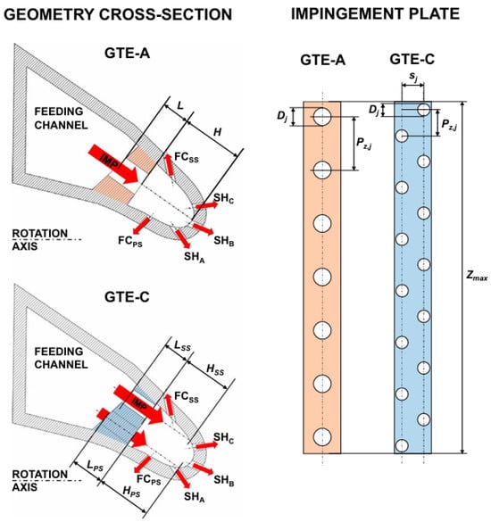
Figure 1.
Schematic diagram of impingement cooling hole geometry [3].
Wang et al. [4] compared two different injection methods: axial and tangential jetting, finding that tangential jetting provides a more uniform heat transfer distribution. At the same time, the local Nusselt number increases with the increase in jet Reynolds number. Salem et al. [5] investigated the effects of linear and staggered nozzle arrangements on cooling performance. They found that as the distance from the jet to the target plate increases, the peak local Nusselt number decreases, and the staggered nozzle arrangement negatively affects cooling performance. Calzada et al. [6] analyzed the cooling effectiveness of two rows of staggered jet holes using transient liquid crystal technology and measured the distribution of heat transfer coefficients under different Reynolds number conditions, providing foundational data for understanding the flow characteristics of this specific configuration. He et al. [7] found that a smaller turning angle of the nozzle leads to counter-rotating vortices and high turbulence intensity along the flow direction. A larger turning inner radius causes the jet flow pattern to transition from impinging jet to a laminar flow adhering to the target surface, thereby affecting heat transfer efficiency. An increase in the jet Reynolds number significantly enhances heat transfer and total pressure loss, and the influence of channel geometric parameters is more pronounced at high Reynolds numbers. Increasing the jet spacing and the distance from the jet to the target surface led to a decrease in pressure drop and heat transfer, with a local minimum observed in their relationship under certain specific conditions. This phenomenon indicates that there exists an optimal combination of jet spacing and distance to the surface, achieving the best heat transfer performance while maintaining a low pressure drop [8]. Based on experimental data, researchers [9] developed a design method that estimates cooling effectiveness through the correlation between the surface Nusselt number and flow coefficient, providing a theoretical basis and practical guidance for the cooling design of low-pressure turbine blades. The dimensionless number Nustag, applicable to the analysis and design of turbine blades, can be expressed by Equation (2):
where s is the distance between the impingement holes, D and d are the diameters of the leading edge and the impingement holes, respectively, and l is the distance between the turbine and the leading edge. The applicable range for the formula is 3000 ≤ Re ≤ 15000, 4 ≤ s/d ≤ 16, 1 ≤ l/d ≤ 10, and 1.5 ≤ D/d ≤ 16. The closer the impingement holes are to the target surface, the higher the Nusselt number and the better the heat transfer performance. Liu et al. [10] studied the effect of tangential jet impingement on heat transfer under different nozzle positions/hole diameter ratios (E/d) and Reynolds numbers. The enhancement of heat transfer due to tangential jet impingement is dependent on the nozzle position and Reynolds number. When the Reynolds number is below 15,000, tangential jet impingement can enhance heat transfer on the target surface, but at a Reynolds number of 20,000, the heat transfer performance decreases as E/d increases. Mukherjee [11] investigated the pressure drop coefficient of the impingement cooling system at the leading edge of turbine blades through model experiments. The influence of a Reynolds number within the test range on the pressure drop coefficient is negligible, but the relative distance between the spray hole and the cooled surface, denoted as H/D (the ratio of the distance from the cooled surface to the jet hole to the hole diameter), has a significant impact on the pressure drop coefficient. To avoid excessive pressure drop coefficients, H/D in turbine blades should be greater than 1, but higher H/D values can reduce the heat transfer coefficient. Bunker et al. [12] used thermal transient testing techniques to study the internal heat transfer characteristics in the leading edge region of turbine blades under impingement cooling without film cooling. The results indicate that heat transfer increases with approximately the 0.6 power of the jet Reynolds number, and it increases with decreasing leading edge sharpness and the distance from the nozzle to the vertex. The spanwise average heat transfer increases with a decrease in the ratio of jet pitch to diameter. With film cooling, in the leading edge region of the turbine blade under impingement cooling, the primary influence on heat transfer is the jet Reynolds number, while the fluid extraction rate has a minor effect. Changes in the spanwise alignment of the impingement nozzles significantly affect the temperature at the leading edge compared to the position of the film cooling holes. Yan et al. [13] investigated the effects of different backflow hole configurations and coolant outflow paths on the cooling effectiveness of turbine blades. The results show that the introduction of backflow channels significantly enhances the area averaged Nusselt number on the target surface compared to the baseline value. In the inline configuration of a single outlet backflow channel, its performance surpasses that of the staggered configuration. However, when both the backflow channel and the impingement channel have outlets, the backflow configuration has a minimal impact on heat transfer performance.
- (b)
- Effect of crossflow
The crossflow effect refers to the phenomenon where the cooling airflow deviates laterally or shifts away from the main flow direction within the internal channels of the turbine blades, particularly in channels equipped with ribs or baffles. This is a common occurrence in the cooling of gas turbine blades. When complex cooling channel designs are employed, the crossflow effect can significantly influence the distribution of the cooling airflow and its cooling capacity.
Wu et al. [14] compared two impingement cooling models, one with baffles and one without (as shown in Figure 2, to study the effects of high-temperature conditions, the presence of baffles, and the temperature ratio between the mainstream and the coolant on cooling performance. The results indicated that the use of baffles can prevent the deterioration of heat transfer caused by crossflow and, compared to traditional designs, can improve the cooling effectiveness at the leading edge of the blades by over 30 K temperature difference. Furthermore, under real operating conditions of gas turbines, two new correlations were proposed for the surface-averaged Nusselt number with respect to the jet Reynolds number and temperature ratio. The correlation between the surface-averaged Nusselt number (Nu), the Reynolds number (Rej), and the temperature ratio (TR) for the model with separators can be expressed as Equation (3). For the model without separators, the correlation between the surface-averaged Nu and Rej is shown in Equation (4).
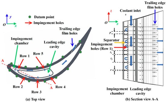
Figure 2.
Geometry of the tested blade with impingement cooling [14].
Alzahrani et al. [15] found that the crossflow effect in channels with a smaller distance between the jet orifice and the target surface is significantly greater than in those with a larger distance. The impact of increased surface roughness on the crossflow effect is negligible, and using long pin designs in narrow channels can enhance the heat transfer performance of impingement channels. Forster et al. [16] studied the heat transfer characteristics of an impinging jet array with a concave target plate. The study utilized an array of nine circular nozzles with a target plate that had the same curvature radius as the nozzle diameter, with film cooling holes staggered around the nozzles. The results showed that while the crossflow effect may reduce heat transfer efficiency, it can make the heat transfer distribution more uniform. Reducing the distance between the nozzle and the target plate can enhance the crossflow effect. Taslim et al. [17] explored the combined effects of impingement cooling and crossflow on heat transfer in cooling channels at the leading edge of airfoils. Through experiments and numerical simulations, they investigated the heat transfer coefficients under different mass flow ratios and jet Reynolds numbers, finding that external crossflow reduces the effectiveness of impingement cooling, particularly in the leading edge and sidewall regions. Even at higher axial-to-jet mass flow ratios, the convective heat transfer coefficient generated by axial flow was found to be lower than that in impingement cooling without crossflow. Elebiary et al. [18] discovered that the crossflow generated by upstream jets significantly affects the impingement effectiveness when studying the impact of various channel arrangements, jet hole configurations, and jet Reynolds numbers on heat transfer coefficients, noting that different channel arrangements also influence heat transfer. He et al. [19] compared the effects of different shapes of crossflow diverters (semi-circular, semi-rectangular, semi-rhombic, and semi-star-shaped) on the heat transfer performance of impingement cooling. The results indicated that all diverters improved the overall heat transfer performance parameters, with the semi-star-shaped diverter showing the best results, achieving a maximum enhancement of 14.7% in heat transfer performance parameters. Chambers et al. [20] investigated the use of elliptical or elongated circular impingement cooling holes in high crossflow channels to enhance the penetration ability of the impinging jet, thereby improving cooling effectiveness. Their findings showed that the average Nusselt number on the impact target surface in the downstream half of the cooling channel increased by 16%, with a 28–77% increase in the Nusselt number for the first four impingement holes in the absence of additional crossflow. Furthermore, properly aligned impingement holes significantly reduced the stress concentration caused by the increase in hole numbers. Zhang et al. [21] studied the impingement cooling effect of asymmetric multi-hole jets in high crossflow channels (as shown in Figure 3) and found that asymmetric hole jets can penetrate the crossflow more effectively than traditional symmetric orifices, thereby improving heat transfer efficiency during impingement cooling, particularly noticeable in short-distance impingement cooling scenarios. The study also revealed that multiple asymmetric hole jets, when maintained at a certain spacing, can provide a more uniform cooling effect.
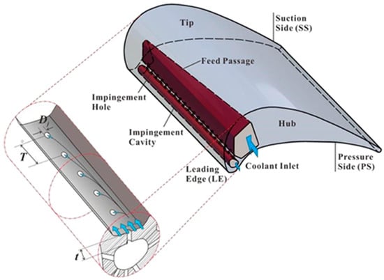
Figure 3.
Internal cooling at the leading edge of a gas turbine blade with a simplified design employing multiple jets [21].
- (c)
- Effects of Ribs
In gas turbine blades, ribs refer to the protruding and recessed structures placed on the surfaces of the internal cooling channels, resembling ribs. Their main function is to enhance the cooling effect by increasing the disturbance and turbulence of the cooling airflow, especially when high-temperature gases flow through the interior of the blades. Ribs are commonly used to improve the heat transfer efficiency between the cooling airflow and the blade surfaces, effectively reducing the temperature of the blades. Taslim et al. [22] conducted cooling experiments on four different target surfaces in a blade leading-edge cooling chamber impacted by crossflow jet nozzles: smooth walls, high surface roughness walls, conical protrusion rough walls, and conical radially ribbed rough walls. Compared to smooth surfaces, rough surfaces had limited effects on enhancing the heat transfer coefficient but increased the surface area [23]. The increase in surface area benefits the heat transfer process, and roughening the target surface can enhance the heat exchange, particularly with conical protrusion rough walls producing the highest enhancement in heat transfer efficiency among all tested geometries. Nourin et al. [24] investigated the application of multi-jet impingement cooling technology on turbine blade leading edges with different surface roughness levels, comparing the cooling effects of traditional hemispherical dimples and blade-shaped dimple surfaces. The results showed that hemispherical dimple surfaces achieved a 5–10% efficiency improvement over smooth surfaces, while blade-shaped dimple surfaces improved efficiency by 2–6% over hemispherical dimple surfaces. Kong et al. [25] studied the effects of jet hole offset on the swirling flow structure and heat transfer characteristics in a concave target chamber with different dimple structures and dispersion holes on turbine blade leading edges. The study found that offsetting the jet holes could improve overall heat transfer performance and uniformity of heat transfer on the target surface. Although the introduction of dimple structures reduced the overall average Nusselt number, it increased the total heat transfer rate in the target chamber due to the enhanced heat transfer area. Xiao et al. [26] arranged circumferential ribs in swirling cooling to suppress crossflow and enhance heat transfer effectiveness. Compared to traditional smooth swirling chambers, swirling chambers with circumferential ribs effectively suppressed crossflow, significantly improving jet penetration capabilities, thereby enhancing the intensity of heat transfer in swirling cooling. The optimal thermal performance was achieved with a rib height-to-width ratio of 0.5. Additionally, within the studied range of Reynolds numbers, the heat transfer enhancement effect of circumferential ribs was more pronounced at higher Reynolds numbers.
2.2. Swirling Cooling
Swirling cooling technology increases heat exchange between the airflow and the inner surface of turbine blades by introducing rotational motion into the cooling airflow, thereby forming a swirling airflow within the blades. Due to the rotational characteristics of the swirling airflow, the residence time of the airflow on the blade surface is extended, enhancing the efficiency of heat transfer. The sustained action of the swirling airflow on the surface can provide a more uniform cooling effect. Han et al. [27] compared the swirling chambers with different surface structures and found that circumferential micro-rib structures performed better in terms of fluid flow and cooling performance, effectively preventing the development of axial crossflow, thus, enhancing heat transfer and lowering surface temperatures to achieve a more uniform temperature distribution. Luan et al. [28] calculated and compared the heat transfer and pressure drop characteristics of multi-converging swirling tubes and baseline circular swirling tubes in swirling cooling systems. The results indicated that the multi-converging swirling tube significantly improved the heat transfer rate and uniformity while maintaining a relatively small increase in pressure drop, particularly in the Reynolds number range of 10,000 to 40,000, where its overall average Nusselt number increased by 11.8 to 23.3% compared to the baseline swirling tube. Zhou [29] studied the cooling performance of the double swirl cooling (DSC) internal cooling structure for gas turbine blade leading edges. Compared to traditional cooling methods with multiple parallel nozzles in grooved channels, the DSC structure significantly enhanced heat exchange by generating two counter-rotating swirls, providing a more uniform heat transfer distribution and higher heat transfer rates. The shape of the target channel significantly influenced the cooling performance of the double swirling cooling system. The DSC configuration with the largest aspect ratio of the vertical semi-axis to the horizontal semi-axis exhibited the lowest flow loss, the highest overall average Nusselt number, and optimal thermal performance, with the overall average Nusselt number and cooling performance improved by approximately 30% and 33%, respectively. Different geometric parameters, such as the merging ratio of the two swirling chambers, nozzle inlet hole configuration, and the radius of blunt protrusions, had a significant impact on the DSC cooling performance. Rectangular inlet holes, especially those with a high aspect ratio, significantly improved heat transfer efficiency, while using blunt protrusions instead of sharp edges could enhance heat transfer and reduce total pressure drop [30]. Wang [31] investigated the heat transfer distribution of tangential jet impingement on a semicylindrical surface and systematically analyzed the effects of different jet plate configurations and jet Reynolds numbers on heat transfer performance. For specific jet plate configurations, the Nusselt number showed an increasing trend with the increase in the Reynolds number of the swirling jet. Moreover, in the circumferential direction, the peak position of the Nusselt number depended on the intensity of the swirl, which could occur in the inlet region or the middle region. Under the same jet Reynolds number conditions, the optimal jet plate configuration was found to be D/d = 4 and s/d = 2, which provided the highest Nusselt number distribution. Smaller s/d values allowed for more cooling airflow, significantly enhancing heat transfer efficiency. Conversely, smaller D/d (a larger jet hole diameter) also positively affected the increase in the Nusselt number. The pressure loss coefficients for different configurations were determined, revealing that the pressure loss coefficient generally increased with the increase in the jet Reynolds number. Zhou et al. [32] studied the effects of different nozzle layouts and aperture sizes on impingement/permeation cooling and double vortex/permeation cooling performance, finding that the double vortex layout performed better in improving the overall average Nusselt number and the Nusselt number in the effective cooling area, with variations in aperture size significantly impacting cooling performance.
Bruschewski et al. [33] investigated the sensitivity of the mean velocity field within a swirl chamber to changes in the Reynolds number, swirl intensity, and outlet geometry. They found that when the swirl intensity significantly exceeds the threshold required for vortex breakdown, subcritical behaviors known as flow states II and III occur. These flow states are influenced by the downstream channel region, with flow state III being particularly sensitive to changes in the outlet geometry. Even minor alterations in the outlet can lead to a completely different flow pattern. To design a more robust swirl cooling system, it is necessary to reduce the swirl intensity to avoid reaching flow state III, or to enable the flow to transition from state III back to states II or I. Seibold et al. [34] demonstrated that while the heat transfer enhancement factor in a convergent swirl chamber decreases with increasing convergence angle, the heat transfer enhancement remains relatively high even at the maximum convergence angle. Furthermore, the friction factor and the friction factor enhancement ratio for the convergent swirl chamber show little variation, indicating relatively high hydraulic costs. Further numerical simulations suggested that convergent swirl tubes can suppress vortex breakdown by accelerating fluid flow, causing the flow to transition from sensitive state III to state I, thus reducing the sensitivity to outlet conditions. Such swirl tubes also stabilize the internal double-helix vortex system, improving flow field characteristics [35].
Wang et al. [36] studied the heat transfer and hydrodynamic characteristics of swirl flow in a blade swirl cooling model. They found that co-rotating swirl flows have a weaker impact on heat transfer enhancement and pressure drop ratio. In a two-slot channel, the heat transfer efficiency was approximately 20% lower compared to a single-slot channel. When considering the pressure drop, the two-slot configuration exhibited a larger Reynolds analogy factor than the single-slot configuration.
Additionally, the rotational effects of the blade have a significant impact on the cooling of the blade leading edge. Wang et al. [37] showed that the rotational effect causes a significant upward deflection of the injected flow, which is perpendicular to the rotation axis and has a high blowing ratio, on the suction surface of turbine blades. As the blowing ratio increases, the film cooling performance deteriorates due to film detachment. However, increasing the blowing ratio can weaken the inward deflection effect of the film. Their research further indicated that increasing the rotational Reynolds number weakens the inward deflection of the film on the suction surface of the blade. When the blowing ratio is 0.5, increasing the rotational Reynolds number improves the film coverage and cooling performance. However, when the blowing ratio is greater than or equal to 0.75, the effect of the rotational Reynolds number becomes more complex, and its influence on the single-row film cooling performance depends on the local distribution of the spanwise blowing ratio. Nabeel et al. [38] employed large eddy simulation (LES) to study the effects of rotational on the single-row air film cooling performance and heat transfer coefficient distribution on gas turbine blades. Their study revealed that as the rotational speed increases, the film cooling effectiveness of the blade improves, with particularly significant local film cooling effects on the pressure side. The rotational effect promotes an earlier transition of the boundary layer and significantly increases the transition length on the suction side of the blade.
3. External Cooling
External cooling primarily relies on film cooling methods, where cooling air flows out through dispersed holes or slots on the blade surface, forming a protective film that covers the surface to prevent damage from high-temperature gas. External film cooling is a crucial technique for cooling the leading edge of gas turbine blades. Taslim et al. [39] designed a showerhead-style film hole cooling scheme, which demonstrated a significant enhancement in the heat transfer coefficient at the blade’s leading edge, particularly on the pressure and suction sides. Meanwhile, Zhao et al. [40] used numerical simulations to study the cooling performance of showerhead film cooling for twisted gas turbine blade leading edges, examining the impact of 15 different angle combinations on cooling effectiveness. Their research indicated that the optimal combination of radial and flow twisting angles is 30°, providing essential guidance for film cooling design. In terms of film hole morphology, Moore et al. [41] proposed two novel film hole designs with expansion angles of 7° and 12° for comparison. They found that although the 12° expansion hole exhibited lower adiabatic effectiveness downstream of the showerhead, with a reduction of 10–15%, its design was better at resisting the effects of free flow. This finding suggests that the expansion angle, as a key geometric parameter influencing film hole performance, warrants further investigation in future research. Additionally, Shine et al. [42] focused on the impact of coolant injection angles on the effectiveness of gaseous coolants. Through numerical simulations, they discovered that optimal coolant injector configurations could significantly enhance cooling efficiency, reduce coolant requirements, and improve the heat transfer coefficient downstream of the injector. Dyson et al. [43] explored the effect of cooling hole spacing on overall cooling performance while studying the Biot model for engine matching. They measured changes in film cooling hole spacing from 7.6 to 11.6 d and found that as the spacing increased, the blowing ratio rose proportionally, enhancing both internal and convective cooling, which somewhat compensated for the reduction in coolant. However, when the hole spacing reached p/d = 11.6, the overall performance significantly decreased, indicating that designers should carefully consider the layout of cooling holes. Kong et al. [44] investigated the thermal transfer and flow field characteristics of leading edge models using sweeping jet and film (SJF) combined cooling compared to normal jet and film (NJF) combined cooling. The study used a conjugate heat transfer method for numerical simulations, considering different injection ratios and temperature ratios. The results showed that SJF had a higher total pressure loss coefficient, a relatively flat spanwise average Nusselt number profile, and a higher area-averaged overall cooling efficiency compared to NJF, leading to greater overall cooling efficiency for SJF. External cooling is particularly suitable for rapid cooling, especially in high thermal load areas like the leading edge of blades, effectively protecting them from high-temperature gas flows. It is advantageous in high-temperature regions, improving thermal stability and uniformity while helping to reduce thermal stress. However, it may also consume more cooling gas, leading to airflow losses and decreased efficiency.
4. Composite Cooling Technology
As the operating temperatures and efficiencies of gas turbines continue to increase, cooling technologies are also undergoing constant innovation and optimization. Nowadays, single cooling methods are no longer sufficient to effectively meet the demands for high heat and high heat transfer efficiency. Therefore, composite cooling technologies that combine multiple cooling methods are receiving increasing attention. The most common composite cooling technologies currently include impact-film composite cooling technology and swirl-film composite cooling technology.
4.1. Impingement-Film Composite Cooling
The cooling airflow directly impacts the inner surface of the leading edge of the blade through nozzles, rapidly removing localized heat. At the same time, the cooling gas flows to the surface of the blade through channels or gaps on the blade surface, forming a thin film of cooling gas. This gas film isolates the high-temperature gas flow from the blade surface, reducing the heat transfer to the interior of the blade. This composite cooling method, applied to the leading edge and the area where the airflow passes over the blade, can provide effective cooling without significantly affecting the aerodynamic performance of the blade. A typical impingement-film composite cooling structure is shown in Figure 4 [45]. Fawzy conducted research based on this model to investigate the impact cooling and film cooling performance of differently arranged conical nozzles at the leading edge of gas turbine blades. He analyzed the effects of the Reynolds number and temperature ratio on the flow field and heat transfer characteristics, discovering that the staggered arrangement of cooling nozzles achieved the highest overall Nusselt number and film cooling efficiency among all cooling models. Further studies explored the composite heat transfer cooling effects of different layouts of conical nozzles at the leading edge of gas turbine blades, analyzing internal impact cooling and external film cooling performance under various Reynolds numbers and temperature ratios. The results indicated that the staggered layout of conical nozzles performed best in terms of enhancing cooling efficiency [46].
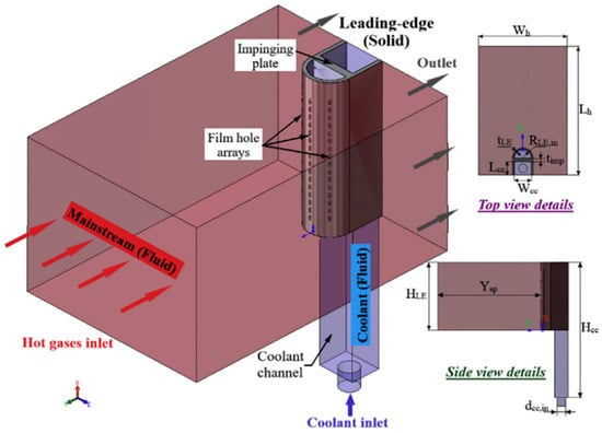
Figure 4.
Leading Edge Impact-Film Composite Cooling Structure [45].
Fu et al. [47] studied the coupled heat transfer and flow field characteristics of a cooling scheme that combines film cooling and impingement cooling on a flat plate. They found that by reasonably distributing the coolant flow, the overall cooling performance can be optimized under specific cooling schemes and given blowing ratios. As the blowing ratio increases, the overall cooling performance approaches its maximum value. The cooling effectiveness of different hole geometries tends to converge at high blowing ratios. With a given coolant mass flow rate, increasing the diameter of the impingement holes leads to a decrease in overall cooling effectiveness. Deng et al. [48] investigated the flow and heat transfer characteristics of a composite cooling structure featuring impingement and film cooling within a rotating channel. Secondary flows and jet deflection generated by rotation affect heat transfer efficiency, improving it on the pressure side while decreasing it on the suction side. Mehdi et al. [49] compared the cooling effectiveness of single film cooling technology with combined cooling techniques of impingement-convection and impingement-film cooling, finding that both combination techniques significantly enhance cooling efficiency and uniformity of temperature distribution. Jung et al. [50] studied the effect of impinging jet dual-layer fully shrouded film cooling systems on cooling performance. They evaluated, using infrared thermography, how factors like the angle of film cooling holes, blowing ratio, and height-to-diameter ratio between the film cooling plate and the impinging jet plate impacted overall cooling effectiveness. Increasing impinging jet cooling enhanced total cooling effectiveness, and inclined film cooling holes performed better than vertical ones, with cooling performance improving with increased blowing ratios, but showing little dependence on the height-to-diameter ratio. Experiments further tested the cooling performance of materials with different thermal conductivities (stainless steel, Corian, polycarbonate), analyzing the combined effects of conduction and impinging jet cooling. The results indicated that increasing impinging jets improved the average total cooling effectiveness, which was closely related to the Biot number of the plates [51]. Tang et al. [52] investigated the cooling performance of an integrated impingement/permeation cooling configuration with film cooling holes oriented perpendicularly to the mainstream, as well as the effects of blowing ratio, porous arrangement, hole spacing ratio, and jet-to-target spacing ratio on cooling performance. They found that under low jet-to-target spacing and dense jet arrays, multiple jet impacts could generate higher overall heat transfer through localized extraction of cooling air, and the additional jet impact heat transfer significantly depended on the blowing ratio, porous arrangement, and jet-to-target spacing. Zhang et al. [53] experimentally examined the overall cooling effectiveness of a T-shaped impingement-film cooling method, discovering that the overall cooling effectiveness increased with higher blowing ratios and that variations in convection and geometric parameters significantly affected cooling performance. A nozzle inclination angle of 90 degrees exhibited higher cooling effectiveness due to lower turbulence intensity, while smaller nozzle-to-plate distances helped improve cooling efficiency, with a nozzle diameter of 1.2 mm demonstrating the best cooling performance under a fixed total nozzle area [54]. Taslim et al. [55] studied the effects of different geometric shapes of leading edge wall surfaces and different flow field arrangements on the impingement cooling effectiveness of wall surfaces with film cooling holes, finding that the presence of film cooling holes significantly enhanced the impingement heat transfer coefficient, with small conical protrusions performing best in enhancing internal impingement heat transfer coefficients, resulting in a 95% increase in overall heat transfer efficiency compared to smooth wall surfaces. Andrei et al. [56] investigated the internal heat transfer characteristics with racing-type holes and film cooling extraction, using transient liquid crystal technology to measure local Nusselt numbers under varying nozzle Reynolds numbers and lateral flow conditions. They found that the jet Reynolds number significantly affected the heat transfer coefficient, and that cooling extraction at the leading edge and lateral flow conditions had a slight impact on the Nusselt number. Shen et al. [57] proposed a flat plate model with a combined cooling structure of impingement/film cooling, analyzing the effects of different impingement cooling structures and dimpled film cooling holes on overall cooling effectiveness. They discovered that altering the diameter, impact distance, and shape of the impingement cooling holes could improve the internal heat transfer coefficient and overall cooling effectiveness, with the diameter factor having the most pronounced impact. Furthermore, compared to a simple cylindrical reference film cooling hole, the “dimple type 2” film cooling hole significantly enhanced the area-averaged overall cooling effectiveness by 38.69%. Across a blowing ratio range of 0.5 to 2.5, combining “dimple type 2” with the optimal impingement structure yielded a 20.39 to 39.14% increase in overall cooling effectiveness compared to standard impingement structures combined with cylindrical film cooling holes.
4.2. Swirl Film Composite Cooling
The impingement-film composite cooling technology is suitable for localized areas that require rapid cooling (such as the leading edge of a blade) and, subsequently, forms a protective film layer. Its cooling effect is particularly pronounced in localized high-temperature regions, but the stability of the film may be affected by the impact airflow. In contrast, the swirl-film cooling technology designs nozzles or flow channels to create a swirling airflow field within the blade. This flow field can uniformly act on the inner surface of the blade, making it suitable for more uniform and continuous cooling needs, and it enhances the stability of film cooling, especially in cases where large area protection or maintaining the integrity of the film is required.
Fawzy et al. [58] studied the flow and heat transfer characteristics of swirl and impact composite cooling structures at the leading edge of gas turbine blades. The research found that compared to traditional impact cooling, this composite cooling structure significantly improved heat transfer efficiency and thermal uniformity under various Reynolds numbers and temperature ratios, with the overall average Nusselt number increased by 99.7%. Zhang et al. [59] compared the heat transfer performance of jet film cooling and swirl film cooling at the leading edge of blades, focusing on the impact of normal and tangential jet nozzle designs on the internal heat transfer coefficient. The experiments employed a transient liquid crystal method to measure the detailed internal heat transfer distribution. The results indicated that the mainstream airflow alters the coolant flow distribution through the film cooling holes, thereby affecting internal heat transfer. For normal jets, the mainstream airflow significantly increased the Nusselt number at lower Reynolds numbers (5000), but as the jet Reynolds number increased, the influence of the mainstream airflow on heat transfer gradually diminished. Tangential jets improved the Nusselt number across different Reynolds numbers, outperforming normal jets at higher Reynolds numbers. Wang et al. [60] also indicated that the mainstream airflow significantly influences the flow and heat transfer characteristics of vortex cooling, primarily due to the variation in the strength of the suction effect near the film cooling holes caused by the uneven pressure distribution in the mainstream airflow. The study considered two arrangements for the coolant injection holes: on the pressure side and the suction side. The results showed that the vortex structure on the pressure side was displaced, whereas the flow structure on the suction side was almost unaffected by the mainstream airflow. Compared to pure vortex cooling, the average Nusselt number increased by 8.05% and 8.44% when injection holes were arranged on the suction and pressure sides, respectively. In terms of film cooling efficiency, the cooling effectiveness with holes arranged on the suction side was improved by up to 59.8% and 1.5% compared to the pressure side arrangement. This difference mainly arises from the interaction between the coolant film and the mainstream airflow, particularly the secondary flow induced by the mainstream airflow at the end wall, which reduces the effectiveness of film cooling. Du et al. [61] designed two different types of inlet swirl channels for cooling chambers (as shown in Figure 5), namely a slot-type inlet swirl channel and a staggered hole inlet channel. Compared to internal channels without swirl, both swirl designs enhanced internal cooling effectiveness, and the film cooling effectiveness on the pressure side was also improved. The computational results indicated that the average overall cooling effectiveness at the leading edge increased by approximately 75% and 57% for the staggered hole and slot-type inlet swirl channel designs, respectively. Additionally, the design of the staggered hole inlet channel helped improve overall cooling efficiency. However, pressure losses in both designs were greater than those in the non-swirled design, and there was an increase in pressure loss with improved cooling performance. The pressure loss coefficient in the staggered hole inlet design increased by 13.7% compared to the non-swirled design, while the slot-type inlet design only increased by 2.6%.
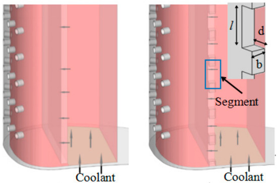
Figure 5.
Slotted and arrayed hole inlet channel cooling chamber configurations [61].
Luan et al. [62] conducted a systematic comparative study of a swirling jet impact cooling system with internal rib walls and film extraction holes, exploring the heat transfer performance of three cooling configurations: typical axial jet impact cooling at the centerline, offset jet swirling impact cooling, and offset jet swirling impact cooling with rib walls (as shown in Figure 6). By comparing different configurations, the study proposed a stepwise optimization strategy for heat transfer: first improving local heat transfer, then achieving linear heat transfer, and finally optimizing planar heat transfer. The research found that the staggered offset jet configuration, combined with rib wall structures, effectively controlled the flow direction and cross-flow, significantly enhancing the spatial uniformity of heat transfer. This optimization strategy provides new insights for improving the cooling efficiency of turbine blades.
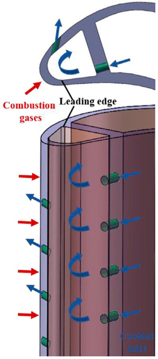
Figure 6.
Schematic of swirl impingement cooling strategy for the turbine blade leading edge [62].
Han et al. [63] proposed a novel double-wall with composite swirl/film cooling structure (as shown in Figure 7), which demonstrated a gradual improvement in the overall cooling performance with an increasing number of cavities, as well as a more uniform distribution. The composite swirling/film cooling structure exhibited a significant heat transfer performance under high Reynolds number and low Biot number conditions, effectively enhancing the cooling effect, with an overall improvement of nearly 9% compared to traditional dual-wall structures. The study also found that the swirling cooling structure increased turbulence intensity by generating annular vortices, thus improving internal heat transfer. Furthermore, the overall cooling effect was highly sensitive to changes in the Biot number. At a low Biot number, the increase in thermal conductivity made internal cooling the dominant factor. However, despite the excellent performance of this composite cooling structure, there are still certain limitations. Due to design constraints of the swirling cavities, the structure requires a combination of injection nozzles, swirling chambers, and film holes to achieve optimal results. Additionally, the curvature of the blades and the complex actual working conditions make it challenging to apply this structure directly to real turbine blades. Therefore, future research should focus on optimizing this cooling structure to meet practical application requirements and assess its flow and heat transfer characteristics under real operating conditions.
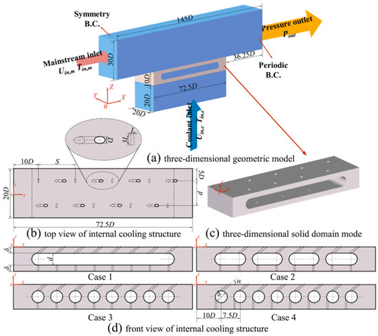
Figure 7.
A novel double-wall with composite swirl/film cooling structure [63].
Han et al. [64], building on the original design, further improved the composite swirl/film double wall cooling structure and proposed a novel serpentine swirl/film double wall cooling solution specifically for turbine blades (as shown in Figure 8). Through numerical simulations, the cooling performance, flow field characteristics, and energy loss of this new cooling structure were analyzed at different blowing ratios and compared with traditional film/impingement dual-wall cooling structures. The results indicated that the new double wall cooling design performed better in terms of cooling effectiveness. Within the blowing ratio range of 0.50 to 2.00, the area-averaged cooling effectiveness of the new structure increased by 6.74 to 7.90% compared to the traditional double wall cooling structure. When applied to blade models, the cooling effectiveness of the new cooling solution improved by 3.80 to 4.39% compared to the traditional structure, while the energy loss coefficient only slightly increased by 0.37 to 0.55%. This new cooling structure not only improved the uniformity of the temperature distribution and suppressed high-temperature deformation of the blades but also enhanced the stability and safety of the blades.
Figure 8.
Serpentine swirl/film double wall cooling [64].
Wang et al. [65] compared several geometric configurations of film holes with different numbers of rows and diameters, analyzing the flow and cooling characteristics of wall jet and film combined cooling structures (as shown in Figure 9) in conjugate heat transfer. Compared to pure wall jet cooling, film extraction can improve overall cooling effectiveness. Additionally, at the base of the blade, particularly on the pressure side, some film holes experienced mainstream flow intrusion. The diameter of the film holes can enhance the mass flow ratio, thereby strengthening the external thermal protection provided by the cooling air, while also affecting the uniformity of the film flow and the temperature gradient in certain areas of the blade.
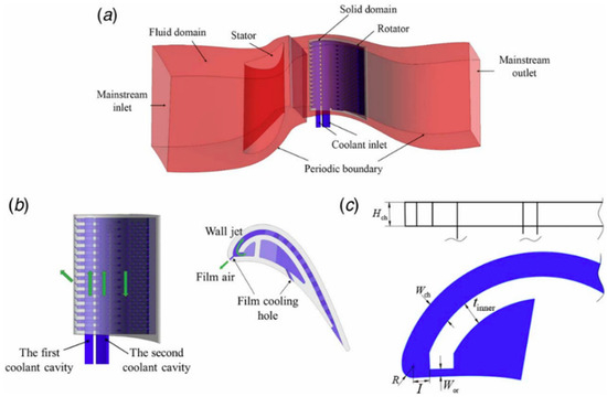
Figure 9.
Film/multi-channel wall jet cooling structure: (a) computational domain, (b) sketch of cooling structure in blade, and (c) scheme of bended cooling channel [65].
Composite cooling technologies offer high cooling efficiency, and in future developments, they could be combined with traditional convective cooling methods, such as gas injection, thermoelectric cooling, and microstructural optimization. These approaches would enhance overall thermal management, improve cooling efficiency, reduce coolant flow requirements, and thereby improve the performance of the entire cooling system.
In addition, high thermal conductivity materials play a critical role in the durability and reliability of blades in high-temperature and high-stress environments. The selection of high thermal conductivity materials is crucial in the composite cooling design for the leading-edge region of gas turbine blades. Common high thermal conductivity materials include alloys, silicon-based ceramic matrix composites, and metal matrix composites. Nickel-based superalloys and cobalt-based alloys are commonly used materials for gas turbine blades. These alloys possess high oxidation resistance and thermal stability, enabling them to withstand the extreme operating conditions of gas turbines. Despite their good oxidation resistance and high-temperature stability, the cooling system must still be designed efficiently to address the thermal gradients between the blade surface and interior, reducing crack propagation due to thermal stress, and improving long-term blade reliability. Silicon-based ceramic matrix composites have exceptional high-temperature resistance, allowing them to function stably in environments above 1600 °C. They also feature a very low thermal expansion coefficient and high thermal conductivity, which helps quickly and uniformly conduct heat. This property effectively reduces thermal stress concentration and thermal fatigue caused by temperature gradients, thus improving blade service life. Metal matrix composites combine the toughness of metals with the high thermal conductivity of ceramics, providing excellent thermal stability and mechanical performance under high-temperature conditions. These materials typically consist of metal matrices, such as aluminum or nickel, combined with ceramic materials like silicon carbide or silicon nitride. Metal matrix composites exhibit higher thermal conductivity than traditional metal alloys, especially at high temperatures. This helps to reduce the thermal stress caused by temperature gradients, mitigating local overheating issues, and thereby improving the durability and reliability of the blades.
4.3. The Influence of Actual Operating Conditions on Blade Cooling
Under practical operating conditions, several real-world factors may significantly affect the cooling of the leading-edge blades, such as thermal gradients, mechanical stresses, and the accumulation of contaminants.
Impact of Thermal Gradients. In practical applications, gas turbine blades are exposed to extreme operating conditions, particularly under high-temperature and high-pressure environments, where the thermal gradient between the surface and the interior of the blade can be substantial. These thermal gradients typically lead to uneven material expansion: different regions of the blade expand to varying degrees due to differing thermal loads. When thermal expansion is non-uniform, it may result in stress concentration within the blade, potentially leading to the formation of micro-cracks, fatigue damage, and other issues. These uneven thermal gradients are critical factors that must be carefully considered during the design of the cooling system, especially when applying high thermal conductivity materials and advanced cooling technologies. Precise thermal analysis is necessary to optimize the arrangement of cooling channels and coolant flow paths in order to minimize thermal stress concentration.
Impact of Mechanical Stresses. After prolonged exposure to high-temperature gas flow, the blades enter a thermal cycling regime, particularly during start-up and shut-down cycles, where rapid temperature fluctuations may exacerbate thermal fatigue effects. This not only impacts the heat exchange efficiency of the cooling system but may also increase the brittleness of the blade material. Mechanical fatigue primarily arises from the alternating aerodynamic loads and centrifugal forces exerted on the blades. The combination of these forces can damage the cooling system, thereby affecting the overall cooling performance. Optimizing the design of the cooling channels (such as using spiral or vortex cooling channels) can help alleviate thermal gradients and stress concentrations, thereby improving the overall performance and reliability of the blades. The use of composite materials with graded thermal conductivity, or the application of specific reinforcement cooling techniques (such as bubble cooling or film cooling) around the cooling channels, can help address thermal fatigue issues under high-temperature conditions.
Impact of Contaminant Accumulation. In high-temperature and high-pressure environments, over time, combustion products and other pollutants present in the turbine’s working environment may deposit within the cooling channels, forming a layer of accumulated contaminants. The presence of these deposits can significantly reduce the thermal exchange capacity of the cooling channels and may lead to blockages in the cooling system, accelerating thermal accumulation and reducing the overall cooling efficiency, which in turn, results in suboptimal temperature control on the blade surface.
Although the leading-edge cooling technology for gas turbine blades has been extensively researched and rapidly developed, we have considered several future research directions based on the existing cooling technologies: (1) Improvement of blade materials, such as using thermal barrier coating materials on the inner and outer surfaces of the blade to isolate high-temperature gas flow from damaging the blade; developing new materials that can withstand higher temperatures and thermal stresses to enhance the durability and thermal stability of the components. (2) In composite cooling structures, using specific surface features, such as ribs, dimples, or heat sinks, on the internal heat exchange surfaces to increase the heat transfer area and improve airflow cooling performance. (3) Optimization of the blade leading-edge shape, film hole configuration, and nozzle parameters using methods such as neural networks. (4) Application of microchannel cooling structures within the internal design of the blade leading edge to enhance heat transfer characteristics while ensuring the structural integrity of the blade.
5. Conclusions
This review summarizes the research progress in external cooling technology, internal cooling technology, and combined film cooling technology for the leading edge of gas turbine blades. The main conclusions are as follows:
- (1)
- External cooling forms a cooling film on the blade surface through film holes, and is generally more suitable for rapid cooling. It can effectively protect the blade from high-temperature airflow, improving thermal stability and uniformity, and helping to reduce thermal stress. However, it may also lead to higher consumption of cooling gas, resulting in airflow losses and efficiency degradation. External film cooling is often influenced by the geometry and arrangement of the film holes, as well as the jet parameters.
- (2)
- For internal jet cooling, factors such as the shape and arrangement of the jet holes, jet distance, Reynolds number, and jet recirculation have a significant impact on the leading edge cooling effect. Smaller jet spacing enhances lateral flow effects, which help achieve more uniform heat transfer but may also reduce cooling efficiency. By optimizing the channel design, reducing nozzle spacing, and using asymmetrical hole injection, the penetration ability of impingement cooling and the overall cooling effect can be enhanced. Ribs in the internal cooling of gas turbine blades primarily enhance heat transfer by increasing disturbances and turbulence in the cooling airflow. Internal swirl cooling technology improves heat exchange between the cooling airflow and the blade surface by introducing rotating airflow, which extends the residence time of the airflow on the surface, thereby improving heat transfer efficiency. Swirl flow provides more uniform cooling, prevents the formation of axial cross-flow, and improves the uniformity of the temperature distribution.
- (3)
- Composite film cooling technology combines external film cooling with internal jet impingement cooling and swirl cooling through the design of film holes and nozzles, significantly improving the heat transfer efficiency and uniformity of gas turbine blades. Factors such as the Reynolds number, injection method (normal or tangential), nozzle design, nozzle hole arrangement, and cooling chamber structure have a significant impact on the composite film cooling performance. Swirl film composite cooling has advantages in improving the Nusselt number, cooling uniformity, and reducing thermal gradients, especially under conditions of a high Reynolds number and a low Bi number. However, it should be noted that the improvement in cooling performance is typically accompanied by higher pressure losses, and design optimization needs to strike a balance between cooling effectiveness and energy loss.
Author Contributions
Conceptualization, C.Z.; methodology, C.Z.; investigation, Y.L.; writing—original draft preparation, Y.L., J.Y. and S.Z.; writing—review and editing, S.Z. and C.Z.; visualization. All authors have read and agreed to the published version of the manuscript.
Funding
This research is supported by the National Natural Science Foundation of China (No. 51976139) and Key Demonstration Project of Technology Breakthrough Project (No. 2024-Technological Breakthrough—High Technology-1).
Conflicts of Interest
The authors declare no conflicts of interest.
References
- McInturff, P.; Suzuki, M.; Ligrani, P.; Nakamata, C.; Lee, D.H. Effects of hole shape on impingement jet array heat transfer with small-scale, target surface triangle roughness. Int. J. Heat Mass Transfer. 2018, 127, 585–597. [Google Scholar] [CrossRef]
- Mohamad, K.K.; Sherif, A.M.; Attalla, M.; Hussein, M.M. Cooling of gas turbine blade leading edge via an array of air jets with variable diameters. J. Heat Transfer. 2022, 144, 123801. [Google Scholar]
- Paccati, S.; Cocchi, L.; Mazzei, L.; Andreini, A. Numerical investigation on the effect of rotation and holes arrangement in cold bridge-type impingement cooling systems. J. Turbomach. 2020, 142, 041004. [Google Scholar] [CrossRef]
- Wang, N.; Chen, A.F.; Zhang, M.J.; Han, J.-C. Turbine blade leading edge cooling with one row of normal or tangential impinging jets. J. Heat Transfer. 2018, 140, 062201. [Google Scholar] [CrossRef]
- Salem, A.R.; Nourin, F.N.; Abousabae, M.; Amano, R.S. Experimental and numerical study of jet impingement cooling for improved gas turbine blade internal cooling with in-line and staggered nozzle arrays. J. Energy Resour. Technol. 2021, 143, 012103. [Google Scholar] [CrossRef]
- De La Calzada, P.; Alvarez, J.J. Experimental investigation on the heat transfer of a leading edge impingement cooling system for low pressure turbine vanes. J. Heat Transfer. 2010, 132, 122202. [Google Scholar] [CrossRef]
- He, W.; Deng, Q.H.; Yang, G.Y.; Feng, Z.P. Effects of turning Angle and turning internal radius on channel impingement cooling for a novel internal cooling structure. J. Turbomach. 2021, 143, 091005. [Google Scholar] [CrossRef]
- Kulkarni, R.V.; Wright, L.M. Parametric study and correlation of racetrack shaped jets for leading edge impingement. J. Heat Transfer. 2022, 144, 103801. [Google Scholar] [CrossRef]
- Chupp, R.E.; Helms, H.E.; McFadden, P.W.; Brown, T.R. Evaluation of internal heat-transfer coefficients for impingement-cooled turbine airfoils. J. Aircr. 1969, 6, 203–208. [Google Scholar] [CrossRef]
- Liu, L.L.; Zhu, X.C.; Liu, H.; Du, Z.H. Effect of tangential jet impingement on blade leading edge impingement heat transfer. Appl. Therm. Eng. 2018, 130, 1380–1390. [Google Scholar] [CrossRef]
- Mukherjee, D.K. Pressure loss coefficient of impingement cooled leading edge system of a turbine blade. J. Eng. Power 1976, 98, 554–556. [Google Scholar] [CrossRef]
- Bunker, R.S.; Metzger, D.E. Local heat transfer in internally cooled turbine airfoil leading edge regions: Part II-Impingement cooling without film coolant extraction. J. Turbomach. 1990, 112, 451–458. [Google Scholar] [CrossRef]
- Yan, H.; Luo, L.; Heo, J.H.; Du, W.; Wang, S.T.; Moon, H.K.; Cho, H.H. Numerical evaluation of a new impingement cooling scheme with a separate return-channel applied to turbine blade leading edge. Appl. Therm. Eng. 2023, 221, 119906. [Google Scholar] [CrossRef]
- Wu, W.L.; Yao, R.; Wang, J.H.; Su, H.; Wu, X.Y. Leading edge impingement cooling analysis with separators of a real gas turbine blade. Appl. Therm. Eng. 2022, 208, 118275. [Google Scholar] [CrossRef]
- Yasser, S.A.; Wright, L.M.; Han, J.-C. Effects of jet-to-target surface spacing and pin-fin height on jet impingement heat transfer in a rectangular channel. J. Therm. Sci. Eng. Appl. 2023, 15, 031003. [Google Scholar]
- Forster, M.; Weigand, B. Experimental and numerical investigation of jet impingement cooling onto a concave leading edge of a generic gas turbine blade. Int. J. Therm. Sci. 2021, 164, 106862. [Google Scholar] [CrossRef]
- Taslim, M.E.; Bethka, D. Experimental and numerical impingement heat transfer in an airfoil leading-edge cooling channel with cross-flow. J. Turbomach. 2009, 131, 011021. [Google Scholar] [CrossRef]
- Elebiary, K.; Taslim, M.E. Experimental/numerical crossover jet impingement in an airfoil leading-edge cooling channel. J. Turbomach. 2012, 135, 011037. [Google Scholar] [CrossRef]
- He, J.; Deng, Q.H.; Xiao, K.; Feng, Z.P. Heat transfer enhancement of impingement cooling by different crossflow diverters. J. Heat Transfer. 2022, 144, 042001. [Google Scholar] [CrossRef]
- Chambers, A.C.; Gillespie, D.R.H.; Ireland, P.T.; Kingston, R. Enhancement of impingement cooling in a high cross flow channel using shaped impingement cooling holes. J. Turbomach. 2010, 132, 021001. [Google Scholar] [CrossRef]
- Zhang, C.Y.; Liu, Y.Y.; Bhaiyat, T.I.; Schekman, S.W.; Lu, T.J.; Kim, T. Impingement cooling by multiple asymmetric orifice jets. J. Heat Transfer. 2022, 144, 042301. [Google Scholar] [CrossRef]
- Taslim, M.E.; Setayeshgar, L.; Spring, S.D. An experimental evaluation of advanced leading edge impingement cooling concepts. J. Turbomach. 2001, 123, 147–153. [Google Scholar] [CrossRef]
- Taslim, M.E.; Bakhtari, K.; Liu, H. Experimental and numerical investigation of impingement on a rib-roughened leading-edge wall. J. Turbomach. 2003, 125, 682–691. [Google Scholar] [CrossRef]
- Nourin, F.N.; Amano, R.S. Heat transfer augmentation with multiple jet impingement cooling on dimpled surface for gas turbine blades. J. Energy Resour. Technol. 2023, 145, 022101. [Google Scholar] [CrossRef]
- Kong, D.-H.; Zhang, C.X.; Ma, Z.Y.; Liu, C.L.; Isaev, S.A.; Guo, T.; Xie, F. Numerical study on flow and heat transfer characteristics of swirling jet on a dimpled surface with effusion holes at turbine blade leading edge. Appl. Therm. Eng. 2022, 209, 118243. [Google Scholar] [CrossRef]
- Xiao, K.; He, J.; Zheng, P.F.; Feng, Z.P. Effects of circumferential ribs on suppressing cross-flow and enhancing heat transfer in swirl cooling. Int. J. Therm. Sci. 2022, 181, 107785. [Google Scholar] [CrossRef]
- Han, S.H.; Zhang, R.S.; Xing, J.J.; Song, Y.Y.; An, N.; Huo, T.Y.; Zhou, L.P.; Li, L.; Zhang, H.; Du, X.Z. Flow and conjugate heat transfer of swirl chamber with micro-ribs in turbine vane leading edge. J. Therm. Sci. Eng. Appl. 2023, 15, 081004. [Google Scholar] [CrossRef]
- Luan, Y.; Rao, Y.; Weigand, B. Experimental and numerical study of heat transfer and pressure loss in a multi-convergent swirl tube with tangential jets. Int. J. Heat Mass Transfer. 2022, 190, 122797. [Google Scholar] [CrossRef]
- Zhou, J.F.; Wang, X.J.; Li, J.; Hou, W.T. Effects of target channel shapes on double swirl cooling performance at gas turbine blade leading edge. J. Eng. Gas Turbines Power. 2019, 141, 071004. [Google Scholar] [CrossRef]
- Lin, G.; Kusterer, K.; Ayed, A.H.; Bohn, D.; Sugimoto, T.; Tanaka, R.; Kazari, M. Numerical investigation on heat transfer in an advanced new leading edge impingement cooling configuration. Propuls. Power Res. 2015, 4, 179–189. [Google Scholar] [CrossRef]
- Wang, N.; Han, J.-C. Swirl impinging cooling on an airfoil leading edge model at large reynolds number. J. Therm. Sci. Eng. Appl. 2019, 11, 031006. [Google Scholar] [CrossRef]
- Zhou, J.F.; Wang, X.J.; Li, J.; Hou, W.T. Comparison between impingement/effusion and double swirl/effusion cooling performance under different effusion hole diameters. Int. J. Heat Mass Transfer. 2019, 141, 1097–1113. [Google Scholar] [CrossRef]
- Bruschewski, M.; Grundmann, S.; Schiffer, H.-P. Considerations for the design of swirl chambers for the cyclone cooling of turbine blades and for other applications with high swirl intensity. Int. J. Heat Fluid Flow. 2020, 86, 108670. [Google Scholar] [CrossRef]
- Seibold, F.; Ligrani, P.; Yang, X.; Poser, R.; Weigand, B. Heat transfer in convergent swirl chambers for cyclone cooling in turbine blades. Appl. Therm. Eng. 2023, 230, 120744. [Google Scholar] [CrossRef]
- Seibold, F.; Weigand, B. Numerical analysis of the flow pattern in convergent vortex tubes for cyclone cooling applications. Int. J. Heat Fluid Flow. 2021, 90, 108806. [Google Scholar] [CrossRef]
- Wang, D.Y.; Khalatov, A.; Shi-Ju, E.; Borisov, I. Swirling flow heat transfer and hydrodynamics in the model of blade cyclone cooling with inlet co-swirling flow. Int. J. Heat Mass Transfer. 2021, 175, 121404. [Google Scholar] [CrossRef]
- Wang, L.; Li, H.W.; Xie, G.; Zhou, Z.Y. Effect of blowing ratio, rotation, and film hole row location on film cooling on the suction surface of a rotating turbine blade. Int. J. Heat Mass Transfer. 2023, 208, 124048. [Google Scholar] [CrossRef]
- Al-Zurfi, N.; Turan, A. LES of rotational effects on film cooling effectiveness and heat transfer coefficient in a gas turbine blade with one row of air film injection. Int. J. Therm. Sci. 2016, 99, 96–112. [Google Scholar] [CrossRef]
- Taslim, M.E.; Khanicheh, A. Experimental and numerical study of impingement on an airfoil leading edge with and without showerhead and gill film holes. J. Turbomach. 2006, 128, 310–320. [Google Scholar] [CrossRef]
- Zhao, Y.C.; Gao, H.S.; Wen, Z.X.; Yang, Y.Q.; Cheng, H.; Li, Q.; Yue, Z.F. Film cooling of showerhead holes from the twisted leading edge of a gas turbine blade: Complex mainstream characteristics and reasonable angle arrangement. Aerosp. Sci. Technol. 2021, 119, 107208. [Google Scholar] [CrossRef]
- Moore, J.D.; Easterby, C.C.; Bogard, D.G. Effects on film cooling performance in the showerhead from geometric parameterization of shaped hole designs. J. Turbomach. 2022, 144, 091006. [Google Scholar] [CrossRef]
- Shine, S.R.; Kumar, S.S.; Suresh, B.N. Internal wall-jet film cooling with compound angle cylindrical holes. Energy. Convers. Manag. 2013, 68, 54–62. [Google Scholar] [CrossRef]
- Dyson, T.E.; Bogard, D.G.; Piggush, J.D.; Kohli, A. Overall effectiveness for a film cooled turbine blade leading edge with varying hole pitch. J. Turbomach. 2013, 135, 031011. [Google Scholar] [CrossRef]
- Kong, X.R.; Zhang, Y.F.; Li, G.Q.; Lu, X.G.; Zhu, J.Q.; Xu, J.L. Heat transfer and flow structure characteristics of film-cooled leading edge model with sweeping and normal jets. Int. Commun. 2022, 138, 106338. [Google Scholar] [CrossRef]
- Fawzy, H.; Zheng, Q.; Jiang, Y.T. Impingement cooling using different arrangements of conical nozzles in a film cooled blade leading edge. Int. Commun. Heat Mass Transfer. 2020, 112, 104506. [Google Scholar] [CrossRef]
- Fawzy, H.; Zheng, Q.; Jiang, Y.T.; Lin, A.Q.; Ahmad, N. Conjugate heat transfer of impingement cooling using conical nozzles with different schemes in a film-cooled blade leading-edge. Appl. Therm. Eng. 2020, 177, 115491. [Google Scholar] [CrossRef]
- Fu, J.L.; Cao, Y.; Zhang, C.; Zhu, J.Q. Investigation of the conjugate heat transfer and flow field for a flat plate with combined film and impingement cooling. J. Therm. Sci. 2020, 29, 955–971. [Google Scholar] [CrossRef]
- Deng, H.W.; Wang, Z.S.; Wang, J.S.; Li, H. Flow and heat transfer in a rotating channel with impingement cooling and film extraction. Int. J. Heat Mass Transfer. 2021, 180, 121751. [Google Scholar] [CrossRef]
- Zolfagharian, M.M.; Rajabi-Zargarabadi, M.; Mujumdar, A.S.; Valipour, M.S.; Asadollahi, M. Optimization of turbine blade cooling using combined cooling techniques. Eng. Appl. Comp. Fluid Mech. 2014, 8, 462–475. [Google Scholar] [CrossRef][Green Version]
- Jung, E.Y.; Oh, S.H.; Lee, D.H.; Kim, K.M.; Cho, H.H. Effect of impingement jet on the full-coverage film cooling system with double layered wall. Experimental Heat Transfer. 2017, 30, 544–562. [Google Scholar] [CrossRef]
- Jung, E.Y.; Chung, H.Y.; Choi, S.M.; Woo, T.-K.; Cho, H.H. Conjugate heat transfer on full-coverage film cooling with array jet impingements with various Biot numbers. Exp. Therm. Fluid Sci. 2017, 83, 1–8. [Google Scholar] [CrossRef]
- Tan, X.M.; Zhang, J.Z.; Xu, H.S. Experimental investigation on impingement/effusion cooling with short normal injection holes. Int. Commun. Heat Mass Transfer. 2015, 69, 1–10. [Google Scholar]
- Zhang, J.Y.; Yuan, C.; Ji, P.F.; Wei, J.L.; He, X.M. Experimental investigation on the overall cooling effectiveness of t-type impinging-film cooling. Appl. Therm. Eng. 2018, 128, 595–603. [Google Scholar] [CrossRef]
- Zhang, J.Y.; Wei, J.L.; He, X.M.; Li, J.; Luo, D.; Wu, Y. Effects of impingement parameters on impinging-film cooling performance. Heat Transfer. Res. 2021, 51, 1241–1260. [Google Scholar] [CrossRef]
- Taslim, M.E.; Pan, Y.; Spring, S.D. An experimental study of impingement on roughened airfoil leading-edge walls with film holes. J. Turbomach. 2001, 123, 766–773. [Google Scholar] [CrossRef]
- Andrei, L.; Carcasci, C.; Da Soghe, R.; Facchini, B.; Maiuolo, F.; Tarchi, L.; Zecchi, S. Heat transfer measurements in a leading edge geometry with racetrack holes and film cooling extraction. J. Turbomach. 2013, 135, 031020. [Google Scholar] [CrossRef]
- Shen, Y.H.; Wang, W.Z.; Zhang, M.K.; Zhang, C. Effect of different internal impingement structures and cratered film cooling holes on overall cooling effectiveness. J. Braz. Soc. Mech. Sci. Eng. 2024, 46, 300. [Google Scholar] [CrossRef]
- Fawzy, H.; Zheng, Q.; Ahmad, N.; Jiang, Y.T. Optimization of a swirl with impingement compound cooling unit for a gas turbine blade leading edge. Energies 2020, 13, 210. [Google Scholar] [CrossRef]
- Zhang, M.J.; Wang, N.; Han, J.-C. Internal heat transfer of film-cooled leading edge model with normal and tangential impinging jets. Int. J. Heat Mass Transfer. 2019, 139, 193–204. [Google Scholar] [CrossRef]
- Wang, J.F.; Li, L.; Li, J.W.; Wu, F.; Du, C.H. Numerical investigation on flow and heat transfer characteristics of vortex cooling in an actual film-cooled leading edge. Appl. Therm. Eng. 2021, 185, 115942. [Google Scholar] [CrossRef]
- Du, H.F.; Mei, Z.Y.; Zou, J.Y.; Jiang, W.; Xie, D.M. Conjugate heat transfer investigation on swirl-film cooling at the leading edge of a gas turbine vane. Entropy 2019, 21, 1007. [Google Scholar] [CrossRef]
- Luan, Y.-X.; Rao, Y.; Yan, H.J. Experimental and numerical study of swirl impingement cooling for turbine blade leading edge with internal ridged wall and film extraction holes. Int. J. Heat Mass Transfer. 2023, 201, 123633. [Google Scholar] [CrossRef]
- Han, S.H.; Xiang, Z.; Xing, J.J.; Zhang, R.S.; An, N.; Qi, S.Z.; Huo, T.Y.; Liu, Q.L.; Zhou, L.P.; Li, L.; et al. Numerical simulation of composite swirl/film double-wall cooling structures and chamber designs for enhanced overall cooling effectiveness. Int. J. Heat Mass Transfer. 2024, 228, 125664. [Google Scholar] [CrossRef]
- Han, S.H.; Xiang, Z.; Qi, S.Z.; Jia, Y.B.; Guo, T.R.; An, N.; Liu, Q.L.; Huo, T.Y.; Xing, J.J.; Zhang, R.S.; et al. Numerical simulation of composite swirl/film double-wall cooling structures and chamber designs for enhanced overall cooling effectiveness: II. Improvement with serpentine chamber and application in C3X vane. Int. J. Heat Mass Transfer. 2024, 234, 126154. [Google Scholar] [CrossRef]
- Wang, H.H.; Deng, Q.H.; He, W.; Feng, Z.P. Cooling and flow characteristics of multi-channel wall jet structure with film holes at blade leading edge. J. Turbomach. 2023, 145, 061009. [Google Scholar] [CrossRef]


Disclaimer/Publisher’s Note: The statements, opinions and data contained in all publications are solely those of the individual author(s) and contributor(s) and not of MDPI and/or the editor(s). MDPI and/or the editor(s) disclaim responsibility for any injury to people or property resulting from any ideas, methods, instructions or products referred to in the content. |
© 2025 by the authors. Licensee MDPI, Basel, Switzerland. This article is an open access article distributed under the terms and conditions of the Creative Commons Attribution (CC BY) license (https://creativecommons.org/licenses/by/4.0/).