
Numerical Analysis of Combustion and Thermal Performance of a Bluff-Body and Swirl-Stabilized Micro-Combustor with Premixed NH3/H2/Air Flames


Abstract
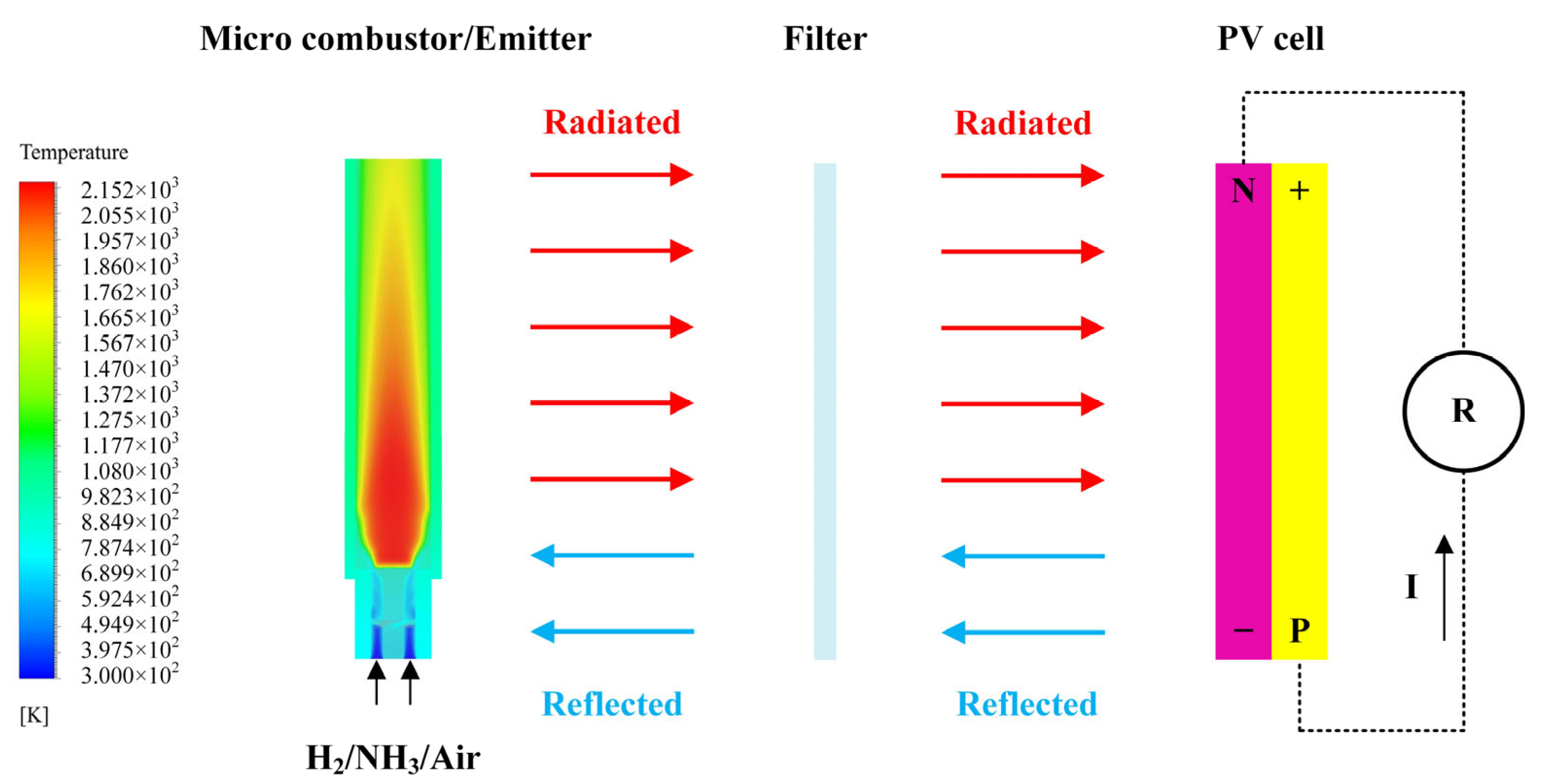
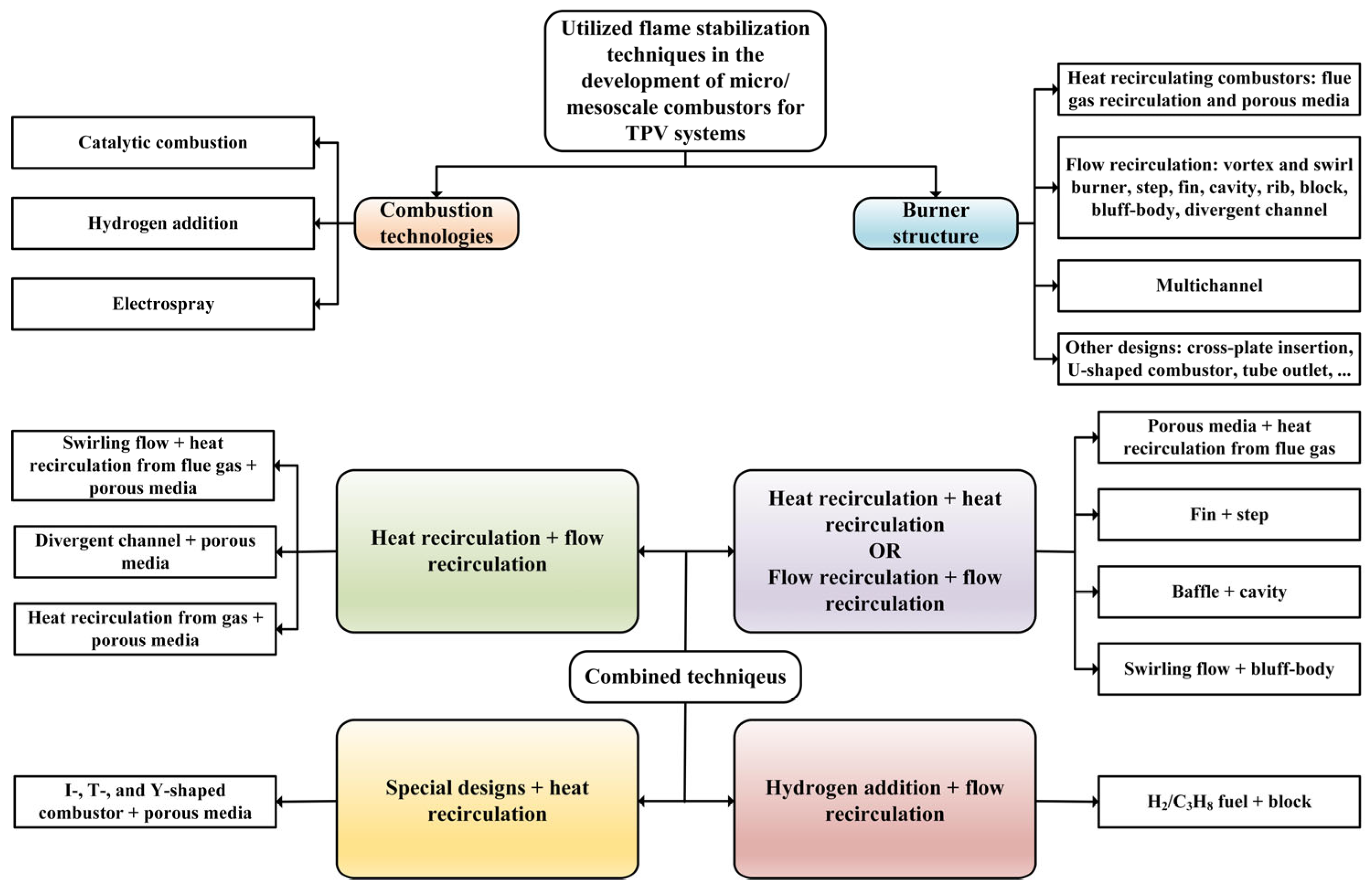
:1. Introduction
2. Physical and Mathematical Model
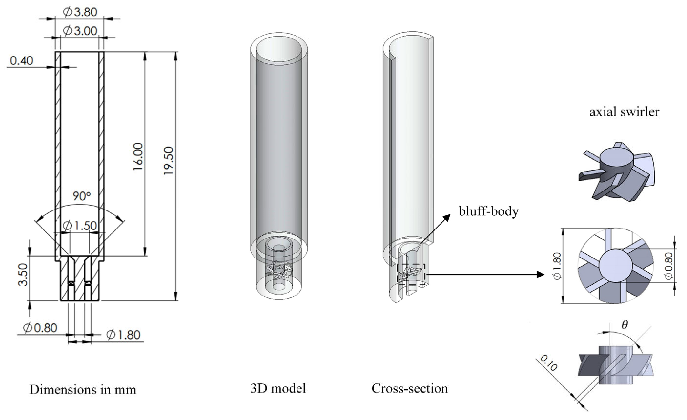
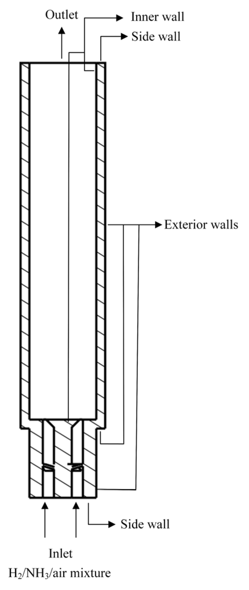
2.1. Physical Model
2.2. Mathematical Model
- Mass conservation:
- Momentum conservation is
- Energy conservation:
- Species conservation:
2.3. Numerical Model and Boundary Conditions
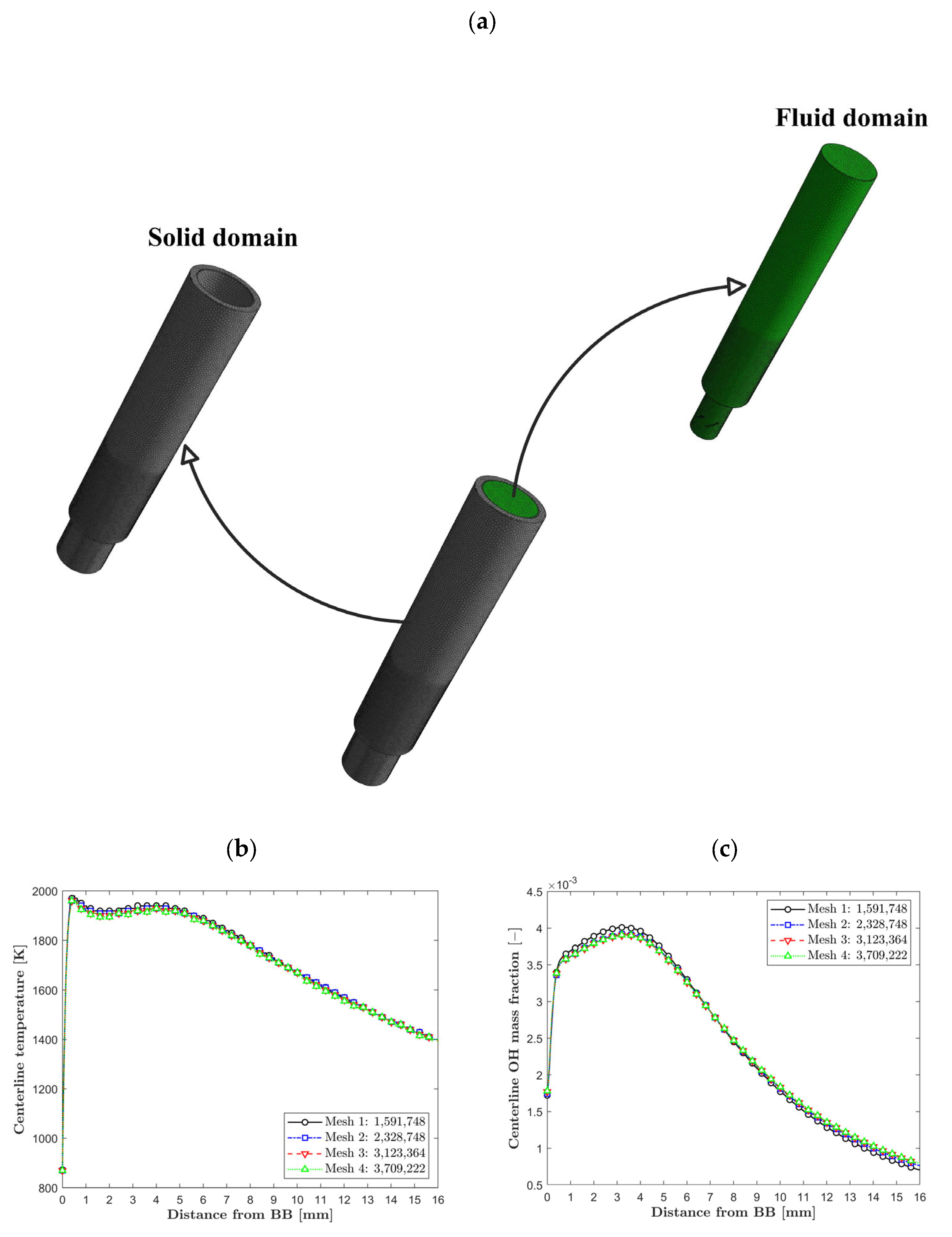
2.4. Analysis of Grid Independence
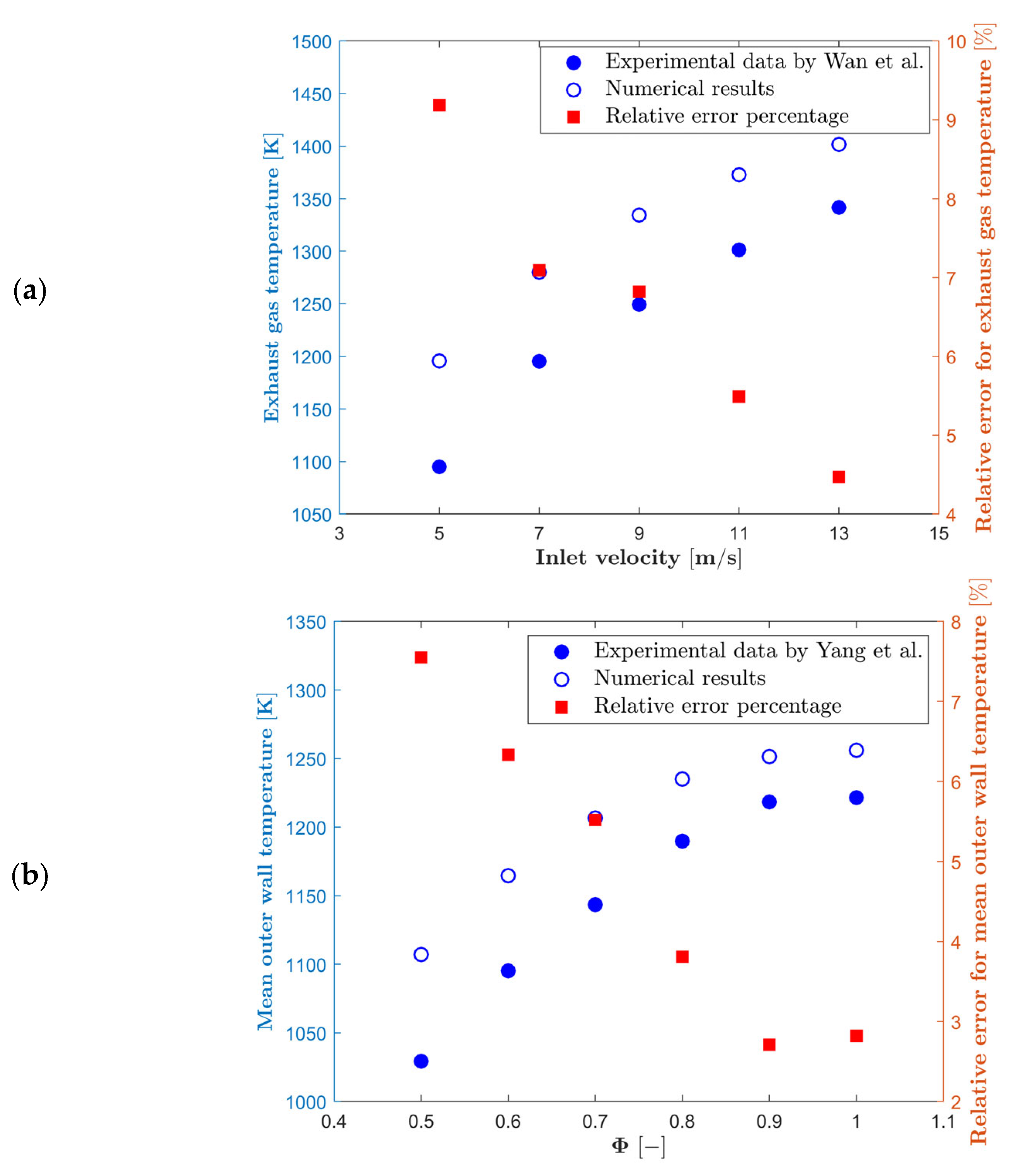
2.5. Validation
3. Results and Discussion
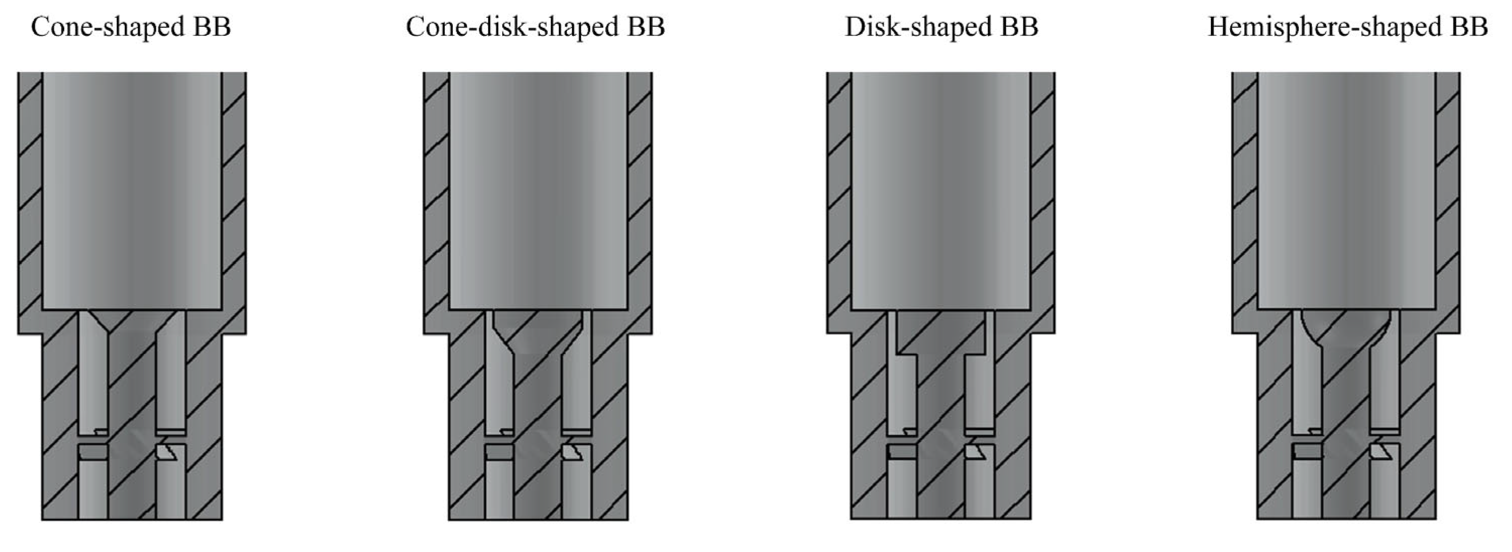
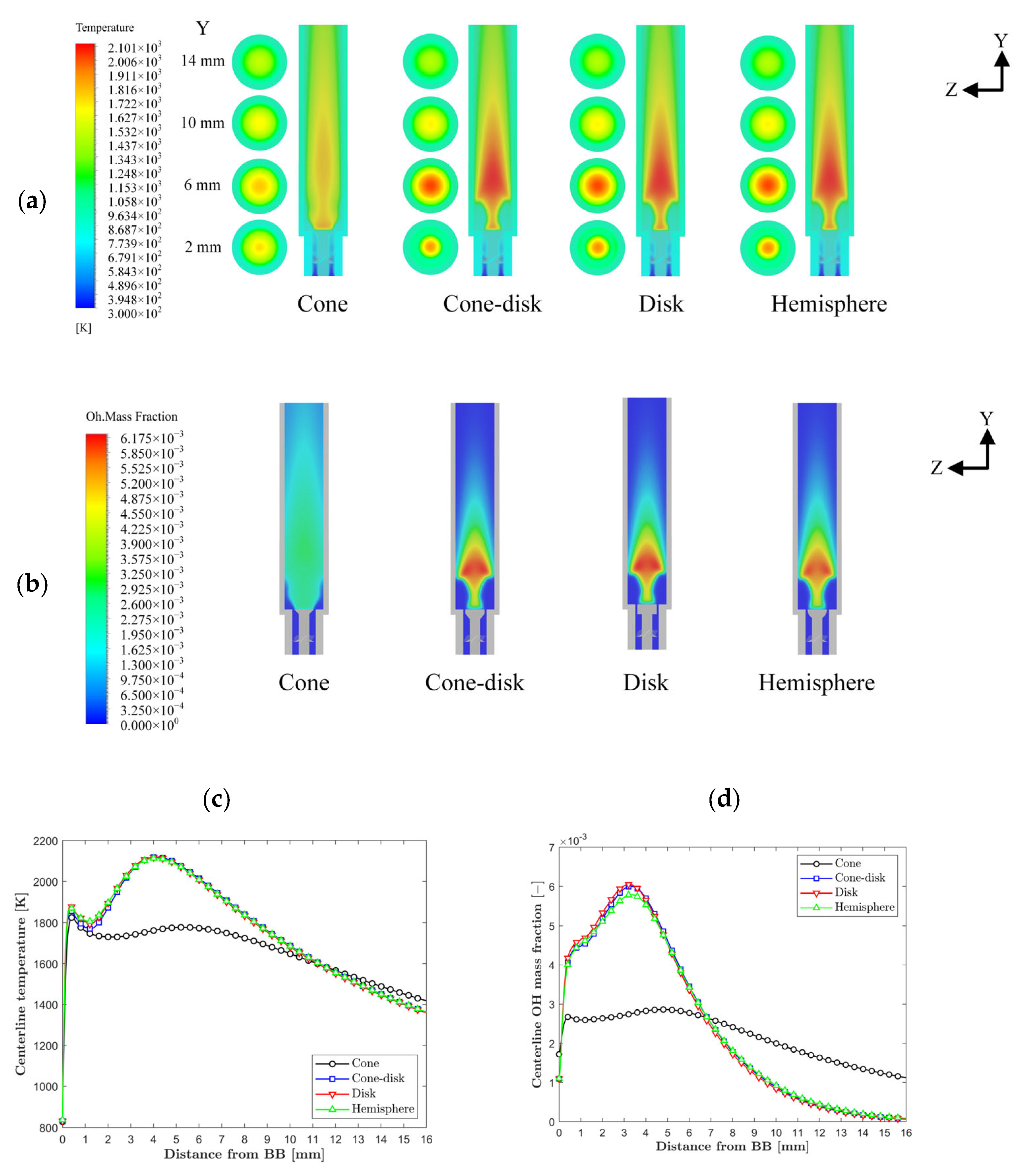
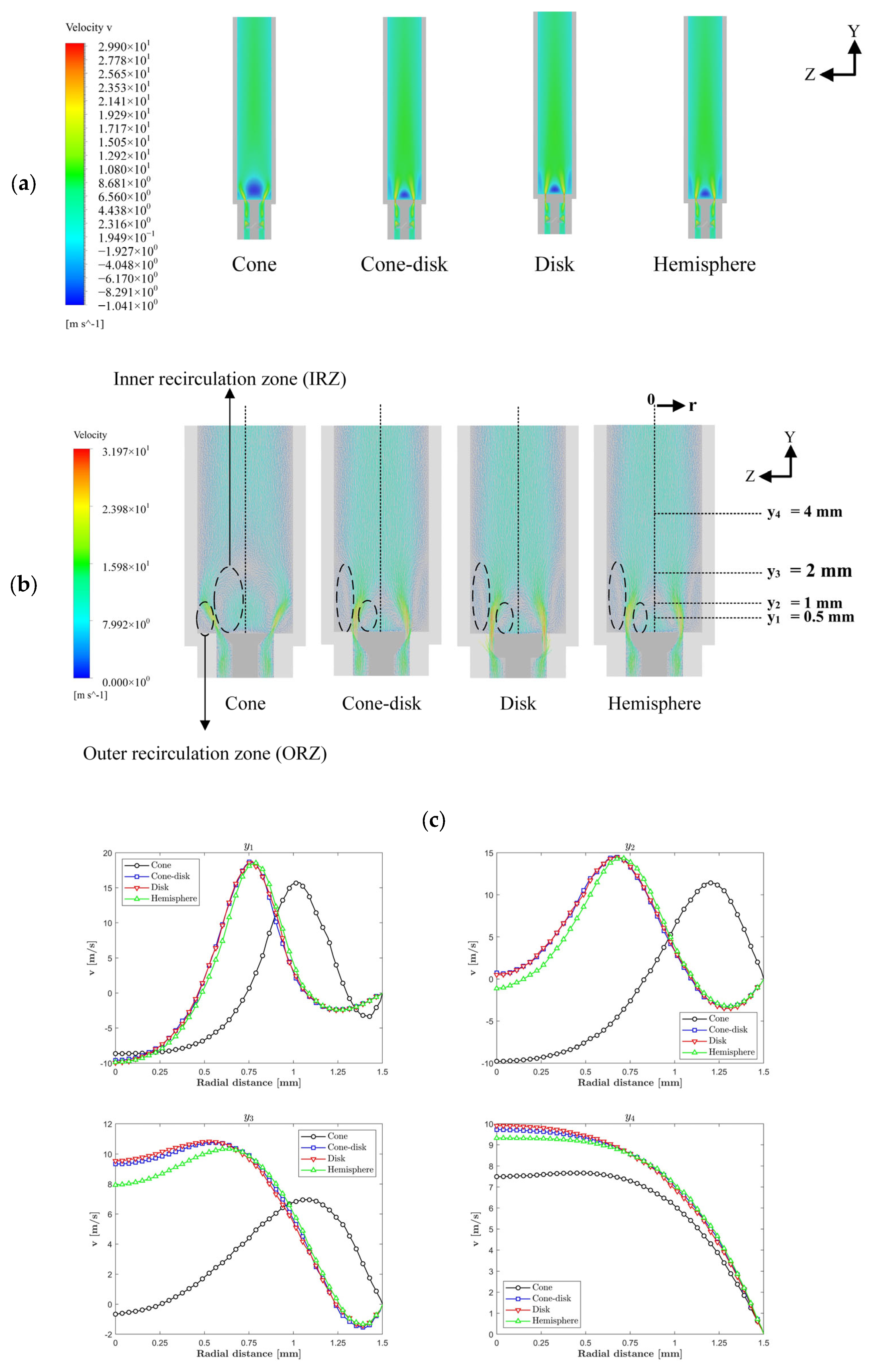
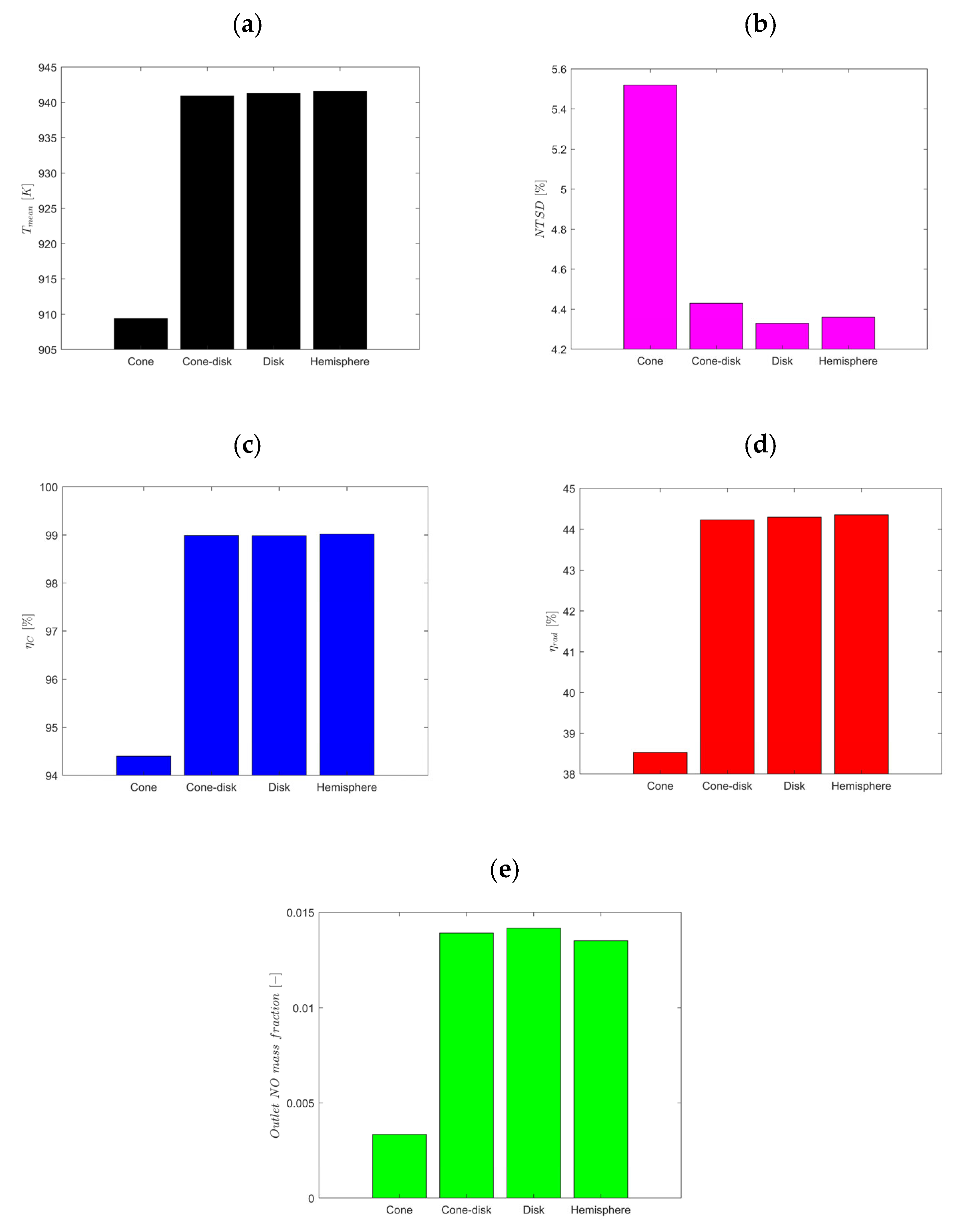
3.1. Effects of Bluff-Body (BB) Geometry
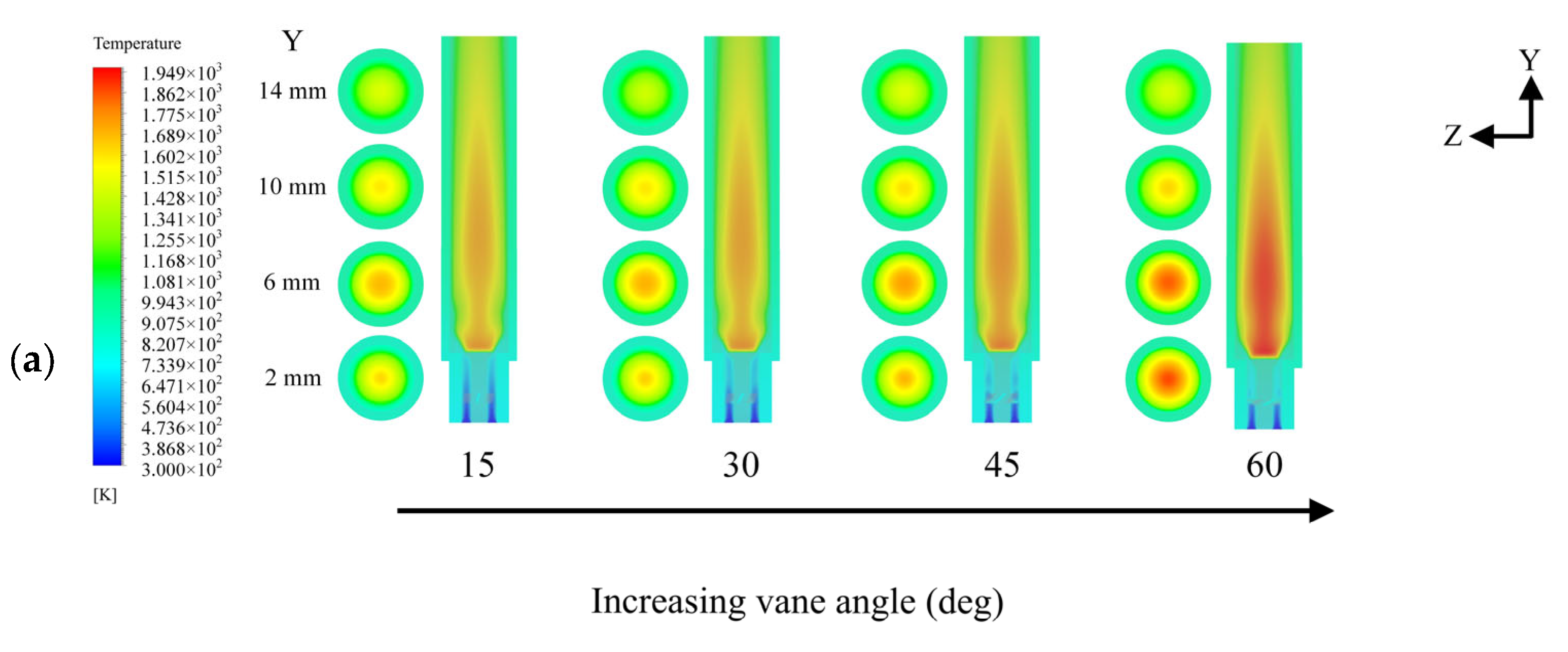
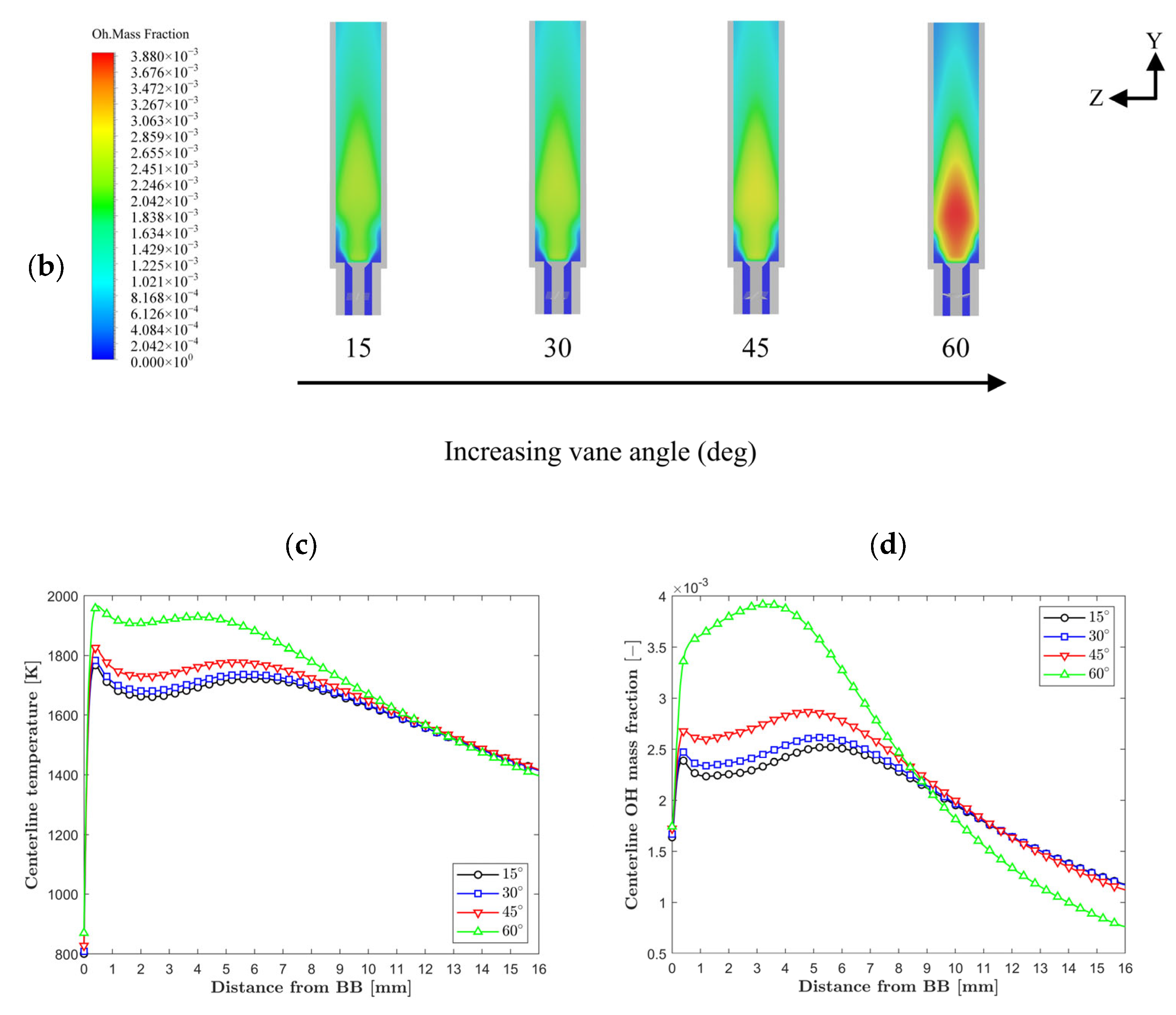
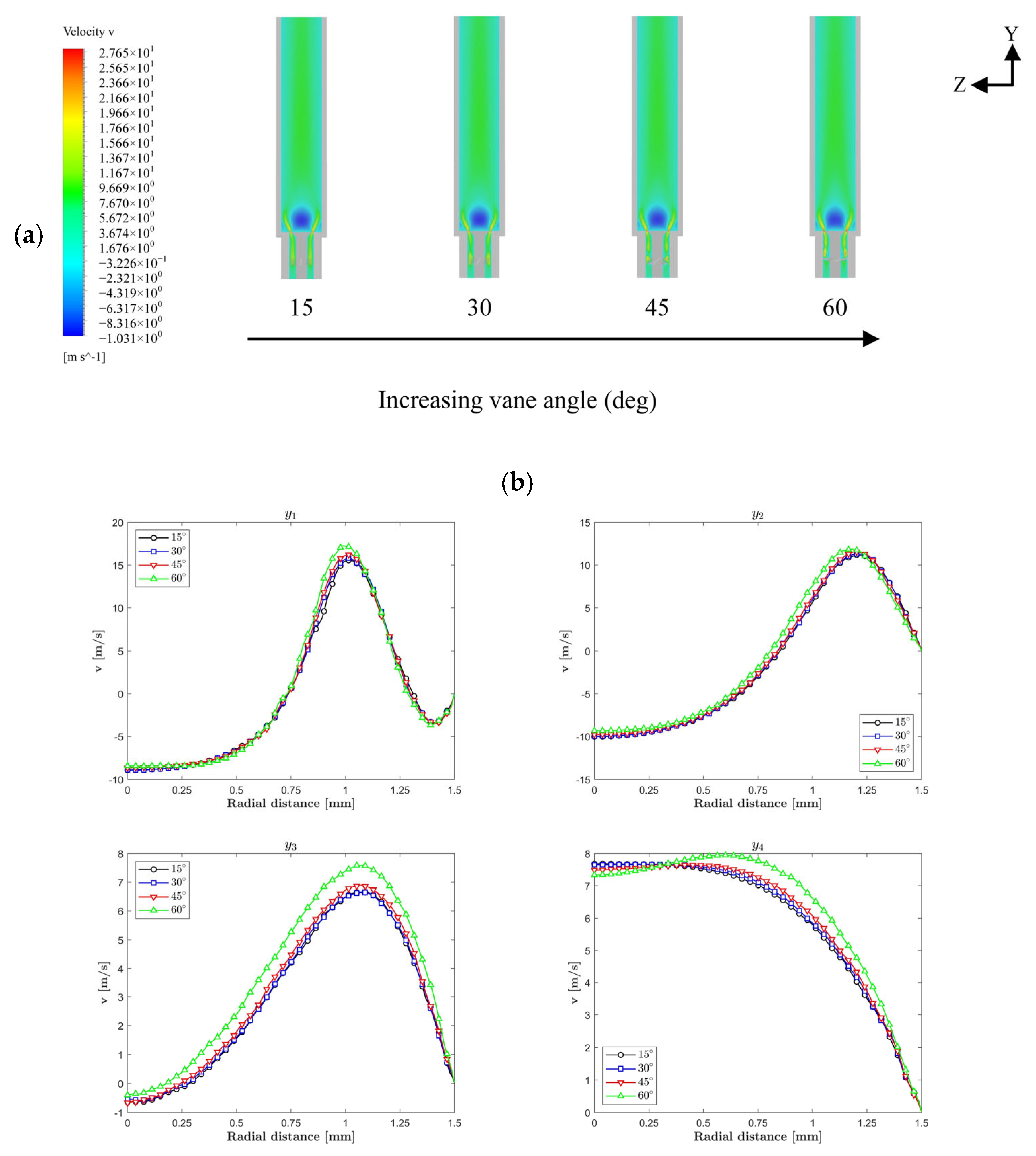
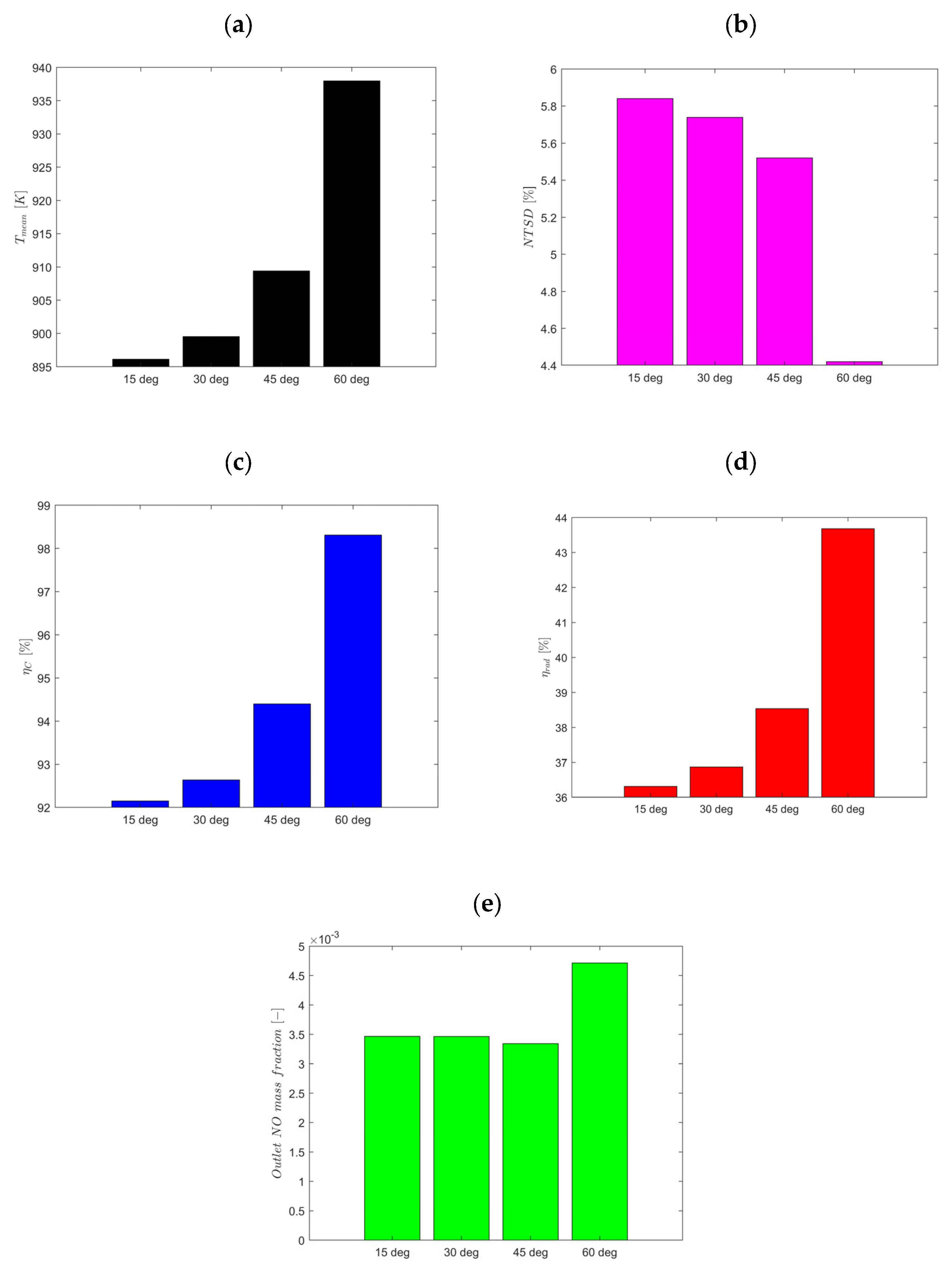
3.2. Effects of Vane Angle
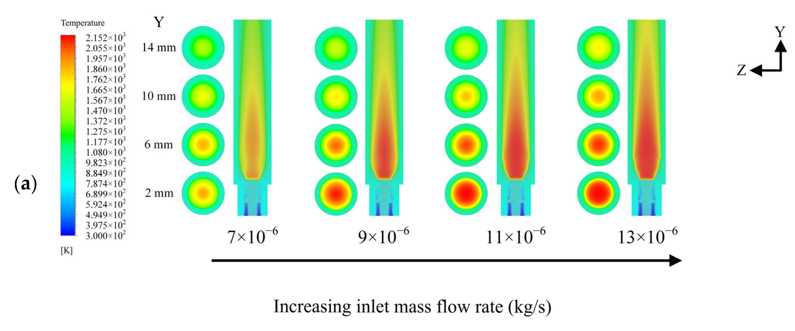
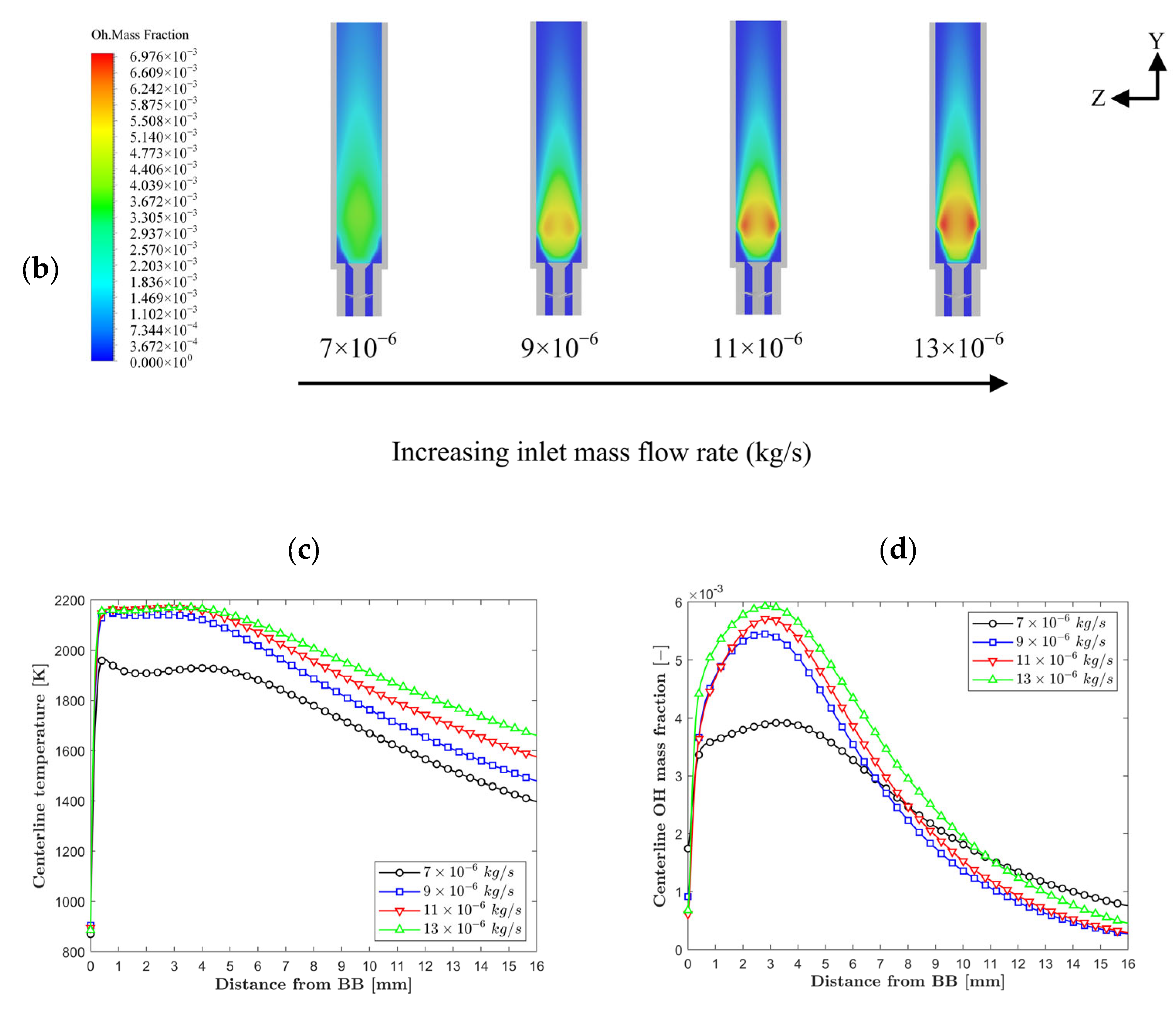
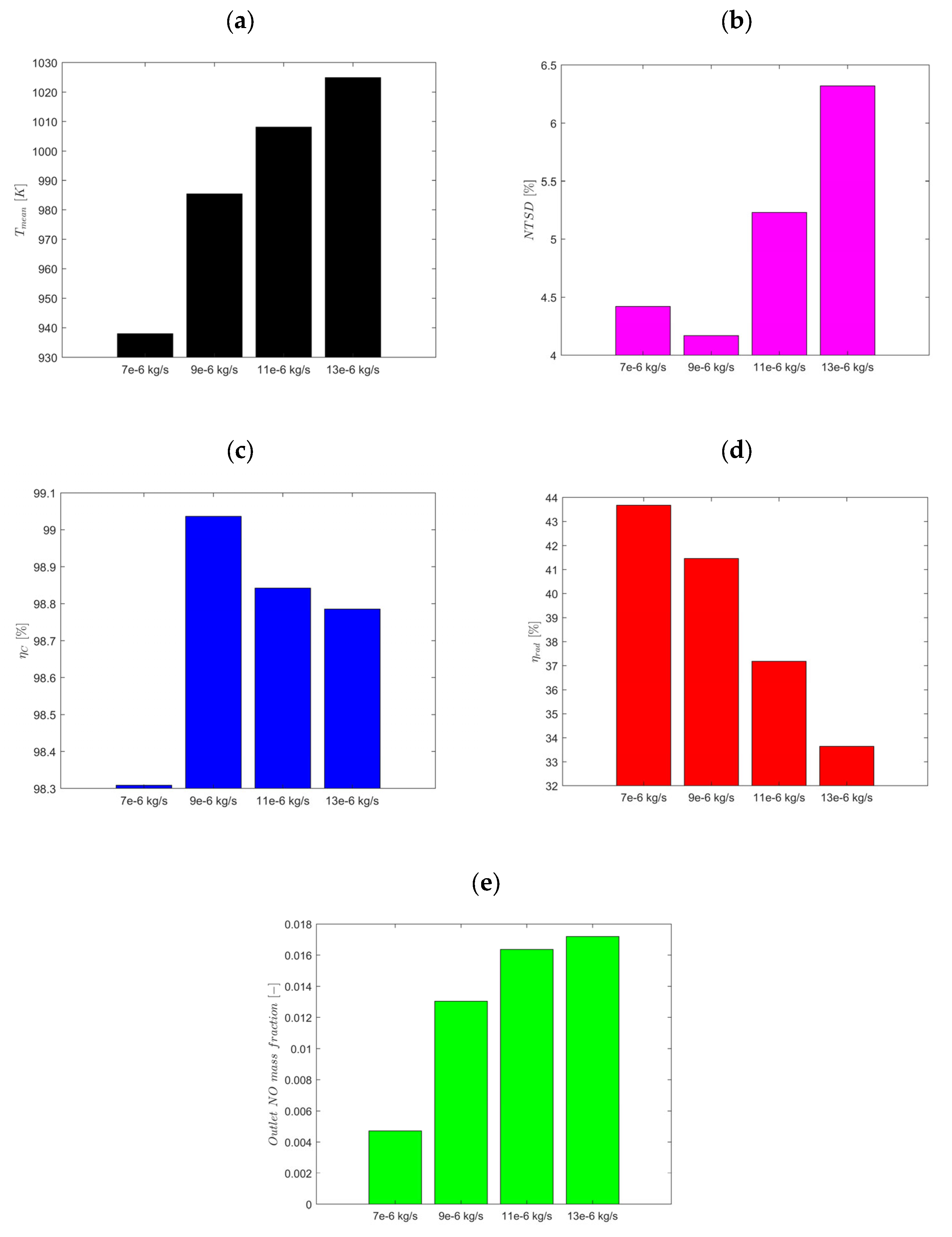
3.3. Inlet Mass Flow Rate Effect
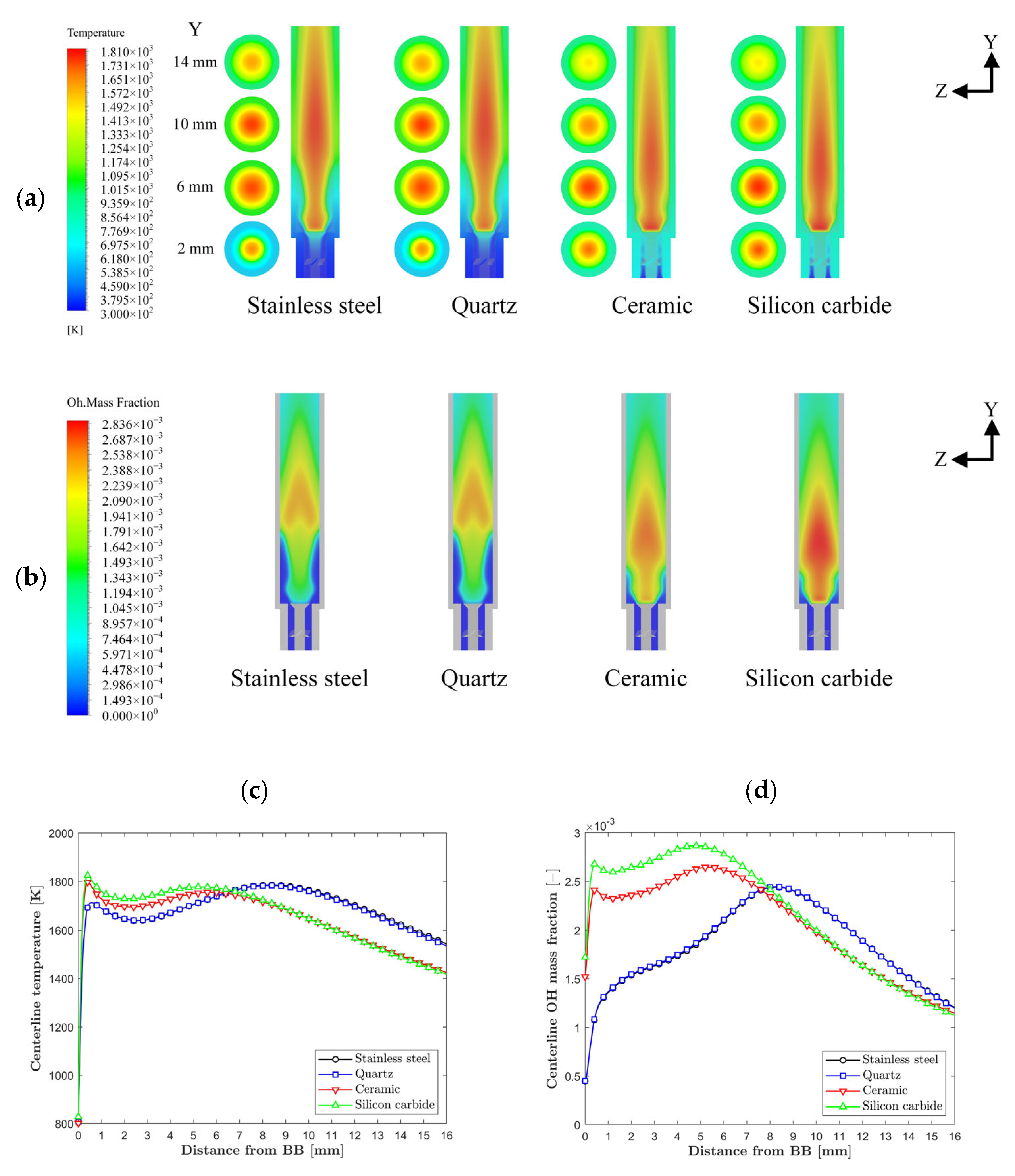
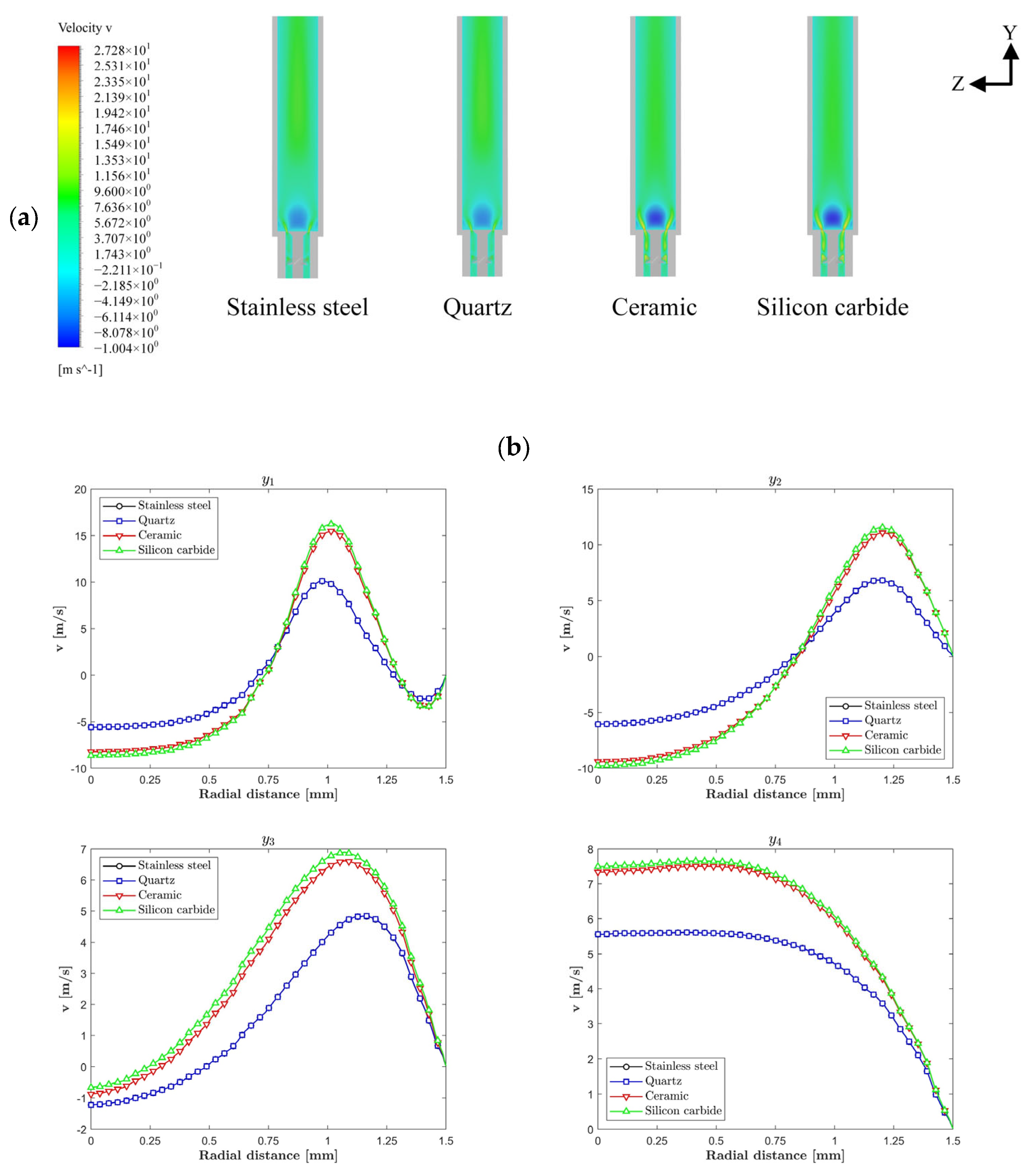
3.4. Effects of Combustor Material
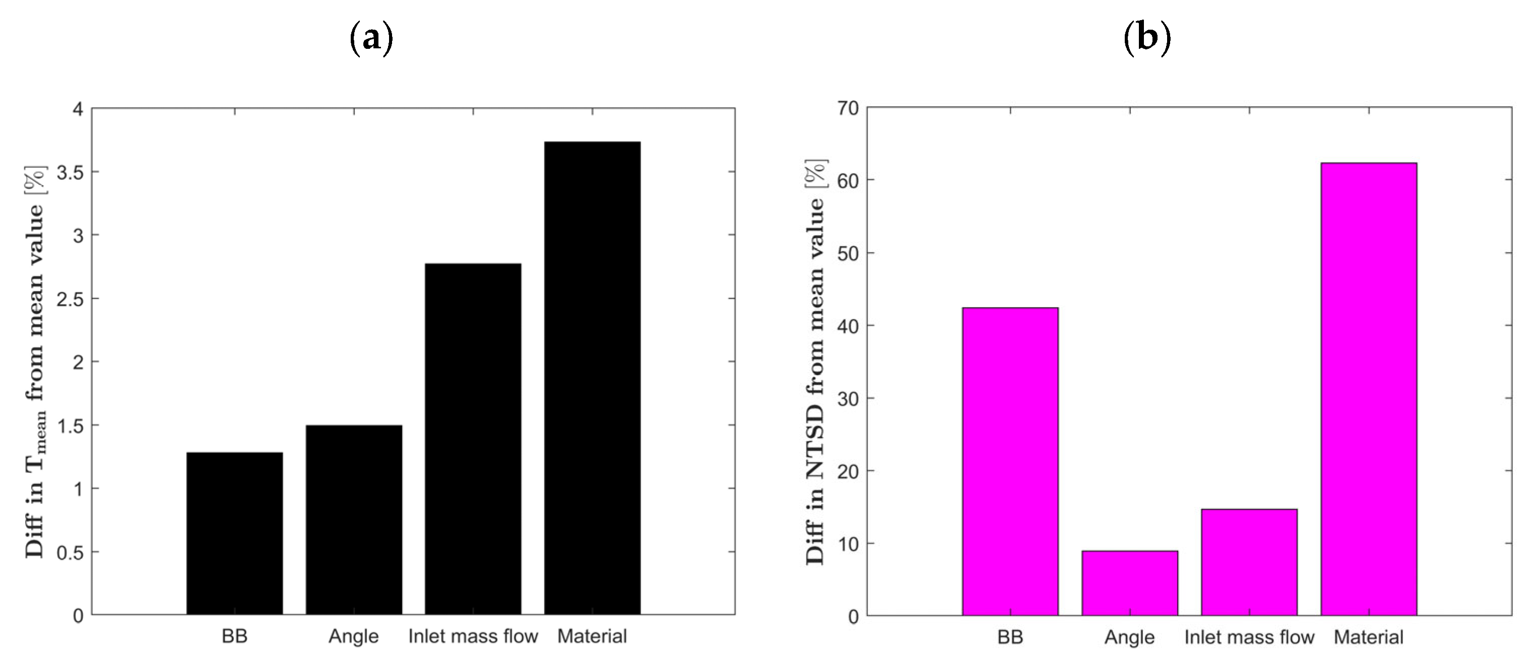
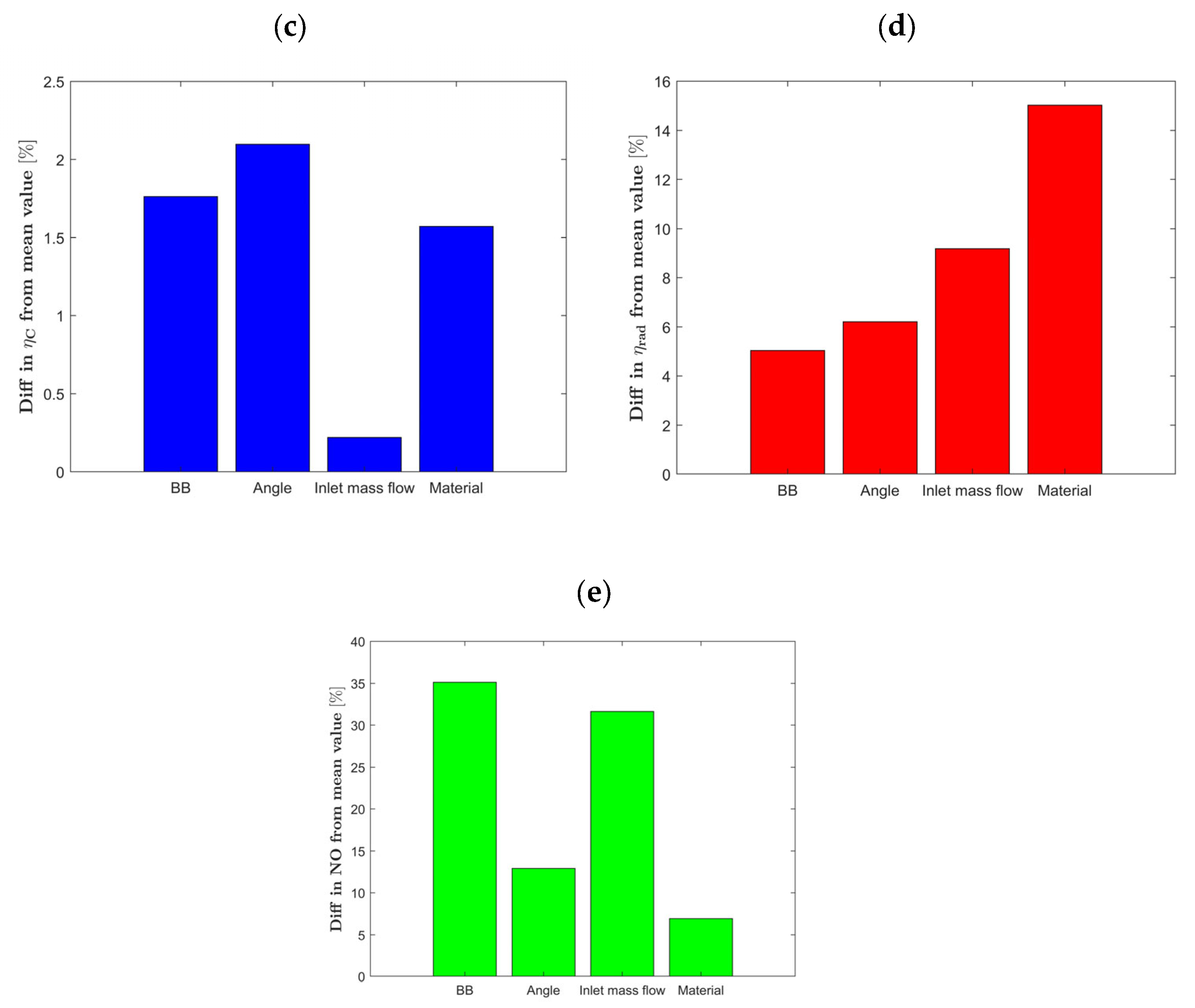
3.5. Sensitivity of Studied Parameters
4. Conclusions
- Bluff-body Geometry: The shape of the bluff-body significantly affects the micro-combustor’s performance. Cone-shaped bluff bodies demonstrated the lowest performance metrics except NO emissions, while the hemisphere-shaped configuration excelled, achieving over 44% radiation efficiency, thus highlighting its effectiveness in designing combustion-based micro-thermophotovoltaic systems;
- Vane Angle of the Swirler: Adjustments to the vane angle significantly impact the combustor’s performance. Transitioning from a 15-degree to a 60-degree vane angle swirler resulted in substantial enhancements, increasing the mean outer wall temperature by 4.6%, combustion efficiency by 6.7%, and radiation efficiency by 20.4%. The 60-degree swirler notably achieved approximately 44% radiation efficiency;
- Inlet Mass Flow Rate: Changes in the inlet mass flow rate directly influence the combustor’s performance, impacting the mean outer wall temperature and NO emissions, while slightly affecting radiation efficiency. Notably, an inlet mass flow rate of 9 × 10⁻⁶ kg/s provided the optimal combustion efficiency of 99% and the most uniform mean outer wall temperature;
- Material Choice: The selection of combustor material profoundly impacts its thermal characteristics and performance. Silicon carbide outperformed other materials, reaching the highest mean outer wall temperature (approximately 910 K) and radiation efficiency (around 38.5%), and exhibited the most uniform outer wall temperature. Conversely, quartz displayed the lowest performance metrics, with a mean outer wall temperature of about 834 K and radiation efficiency of approximately 27.1%. This suggests that opting for silicon carbide could yield more than a 40% improvement in radiation efficiency over quartz.
Author Contributions
Funding
Data Availability Statement
Conflicts of Interest
Nomenclature
| Symbol | Parameter | Symbol | Parameter |
| swirl number | thermal conductivity of solid phase | ||
| swirler hub diameter | temperature of solid phase | ||
| swirler tip diameter | radiation heat transfer | ||
| vane angle of the swirler | convection heat transfer | ||
| density | total heat loss | ||
| specific heat | emissivity | ||
| thermal conductivity | Stefan–Boltzmann constant | ||
| Kn | Knudsen number | exterior surface of the combustor | |
| velocity vector | mean outer wall temperature | ||
| molecular viscosity | surface of element | ||
| unit vector | temperature of element | ||
| overall energy of the fluid | radiation efficiency | ||
| effective conductivity | fuel mass flow rate | ||
| fluid’s temperature | lower heating value | ||
| source term of the fluid enthalpy | normalized temperature standard deviation | ||
| diffusion flux of species | combustion efficiency | ||
| specific enthalpy of that species i | inlet fuel flow rate | ||
| species mass fraction | outlet fuel flow rate | ||
| total rate at which species is produced or consumed through chemical reactions |
References
- Kaisare, N.S.; Vlachos, D.G. A review on microcombustion: Fundamentals, devices and applications. Prog. Energy Combust. Sci. 2012, 38, 321–359. [Google Scholar] [CrossRef]
- Tang, A.; Pan, J.; Yang, W.; Xu, Y.; Hou, Z. Numerical study of premixed hydrogen/air combustion in a micro planar combustor with parallel separating plates. Int. J. Hydrogen Energy 2015, 40, 2396–2403. [Google Scholar] [CrossRef]
- Cai, L.; E, J.; Li, J.; Ding, J.; Luo, B. A comprehensive review on combustion stabilization technologies of micro/meso-scale combustors for micro thermophotovoltaic systems: Thermal, emission, and energy conversion. Fuel 2023, 335, 126660. [Google Scholar] [CrossRef]
- Yang, X.; Zhao, L.; He, Z.; Dong, S.; Tan, H. Comparative study of combustion and thermal performance in a swirling micro combustor under premixed and non-premixed modes. Appl. Therm. Eng. 2019, 160, 114110. [Google Scholar] [CrossRef]
- Chou, S.K.; Yang, W.M.; Chua, K.J.; Li, J.; Zhang, K.L. Development of micro power generators—A review. Appl. Energy 2011, 88, 1–16. [Google Scholar] [CrossRef]
- Jiang, D.; Yang, W.; Teng, J. Entropy generation analysis of fuel lean premixed CO/H2/air flames. Int. J. Hydrogen Energy 2015, 40, 5210–5220. [Google Scholar] [CrossRef]
- Bajelani, M.; Ansari, M.R.; Nadimi, E. A comprehensive study of effective parameters on the thermal performance of porous media micro combustor in thermo photovoltaic systems. Appl. Therm. Eng. 2023, 231, 120846. [Google Scholar] [CrossRef]
- Meng, L.; Li, J.; Li, Q. A miniaturized power generation system cascade utilizing thermal energy of a micro-combustor: Design and modelling. Int. J. Hydrogen Energy 2017, 42, 17275–17283. [Google Scholar] [CrossRef]
- Cadou, C. Microscale Combustion and Power Generation; Momentum Press: New York, NY, USA, 2014; Available online: https://scholar.google.com/scholar_lookup?hl=en&publication_year=2014&author=Y.+Ju&author=C.+Cadou&author=K.+Maruta&title=Microscale+Combustion+and+Power+Generation (accessed on 22 December 2024).
- Li, L.; Yang, G.; Fan, A. Non-premixed combustion characteristics and thermal performance of a catalytic combustor for micro-thermophotovoltaic systems. Energy 2021, 214, 118893. [Google Scholar] [CrossRef]
- Tang, A.; Xu, Y.; Pan, J.; Yang, W.; Jiang, D.; Lu, Q. Combustion characteristics and performance evaluation of premixed methane/air with hydrogen addition in a micro-planar combustor. Chem. Eng. Sci. 2015, 131, 235–242. [Google Scholar] [CrossRef]
- Wei, D.; Peng, Q.; Wang, H.; Tian, X.; Xiao, H.; Liu, H.; Fu, G. Experimental investigation of blended H2/CH4 combustion in combustors with block for micro-thermophotovoltaic. Fuel 2024, 357, 129869. [Google Scholar] [CrossRef]
- Gan, Y.; Chen, X.; Tong, Y.; Zhang, X.; Zhang, Y. Thermal performance of a meso-scale combustor with electrospray technique using liquid ethanol as fuel. Appl. Therm. Eng. 2018, 128, 274–281. [Google Scholar] [CrossRef]
- Wan, J.; Fan, A. Recent progress in flame stabilization technologies for combustion-based micro energy and power systems. Fuel 2021, 286, 119391. [Google Scholar] [CrossRef]
- Zuo, W.; Li, D.; E, J.; Xia, Y.; Li, Q.; Quan, Y.; Zhang, G. Parametric study of cavity on the performance of a hydrogen-fueled micro planar combustor for thermophotovoltaic applications. Energy 2023, 263, 126028. [Google Scholar] [CrossRef]
- Tang, S.; Wei, J.; Xie, B.; Shi, Z.; Wang, H.; Tian, X.; He, B.; Peng, Q. Experimental and numerical investigation on H2-fueled thermophotovoltaic micro tube with multi-cavity. Energy 2023, 274, 127325. [Google Scholar] [CrossRef]
- Sheykhbaglou, S.; Ghahremani, A.; Tabejamaat, S.; Sánchez-Sanz, M. Comparative study of combustion and thermal performance of a meso-scale combustor under co- and counter-rotating fuel and oxidizer swirling flows for micro power generators. Heliyon 2024, 10, e24250. [Google Scholar] [CrossRef]
- Yang, W.; Chou, S.; Pan, J.; Li, J.; Zhao, X. Comparison of cylindrical and modular micro combustor radiators for micro-TPV system application. J. Micromech. Microeng. 2010, 20, 085003. [Google Scholar] [CrossRef]
- Tang, A.; Deng, J.; Xu, Y.; Pan, J.; Cai, T. Experimental and numerical study of premixed propane/air combustion in the micro-planar combustor with a cross-plate insert. Appl. Therm. Eng. 2018, 136, 177–184. [Google Scholar] [CrossRef]
- Zuo, W.; Wang, Z.; E, J.; Li, Q.; Cheng, Q.; Wu, Y.; Zhou, K. Numerical investigations on the performance of a hydrogen-fueled micro planar combustor with tube outlet for thermophotovoltaic applications. Energy 2023, 263, 125957. [Google Scholar] [CrossRef]
- Ni, S.; Zhao, D.; Sellier, M.; Li, J.; Chen, X.; Li, X.; Cao, F.; Li, W. Thermal performances and emitter efficiency improvement studies on premixed micro-combustors with different geometric shapes for thermophotovoltaics applications. Energy 2021, 226, 120298. [Google Scholar] [CrossRef]
- Pizza, G.; Mantzaras, J.; Frouzakis, C.E.; Tomboulides, A.G.; Boulouchos, K. Suppression of combustion instabilities of premixed hydrogen/air flames in microchannels using heterogeneous reactions. Proc. Combust. Inst. 2009, 32, 3051–3058. [Google Scholar] [CrossRef]
- Karagiannidis, S.; Mantzaras, J.; Jackson, G.; Boulouchos, K. Hetero-/homogeneous combustion and stability maps in methane-fueled catalytic microreactors. Proc. Combust. Inst. 2007, 31, 3309–3317. [Google Scholar] [CrossRef]
- Wenming, Y.; Siawkiang, C.; Chang, S.; Hong, X.; Zhiwang, L. Research on micro-thermophotovoltaic power generators with different emitting materials. J. Micromech. Microeng. 2005, 15, S239. [Google Scholar] [CrossRef]
- Yuliati, L.; Seo, T.; Mikami, M. Liquid-fuel combustion in a narrow tube using an electrospray technique. Combust. Flame 2012, 159, 462–464. [Google Scholar] [CrossRef]
- Tang, A.; Cai, T.; Deng, J.; Xu, Y.; Pan, J. Experimental investigation on combustion characteristics of premixed propane/air in a micro-planar heat recirculation combustor. Energy Convers. Manag. 2017, 152, 65–71. [Google Scholar] [CrossRef]
- Bani, S.; Pan, J.; Tang, A.; Lu, Q.; Zhang, Y. Micro combustion in a porous media for thermophotovoltaic power generation. Appl. Therm. Eng. 2018, 129, 596–605. [Google Scholar] [CrossRef]
- Liu, Q.; He, S.; Wang, J.; Xiao, J.; Wang, S. Effects of Central Split Bluff Body on Combustion Characteristics and NOx Emission with Non-Premixed H2/Air Flames. Combust. Sci. Technol. 2023, 1–27. [Google Scholar] [CrossRef]
- Fan, A.; Wan, J.; Liu, Y.; Pi, B.; Yao, H.; Liu, W. Effect of bluff body shape on the blow-off limit of hydrogen/air flame in a planar micro-combustor. Appl. Therm. Eng. 2014, 62, 13–19. [Google Scholar] [CrossRef]
- Wenming, Y.; Siawkiang, C.; Chang, S.; Hong, X.; Zhiwang, L. Effect of wall thickness of micro-combustor on the performance of micro-thermophotovoltaic power generators. Sens. Actuators A Phys. 2005, 119, 441–445. [Google Scholar] [CrossRef]
- Lee, S.; Um, D.; Kwon, O. Performance of a micro-thermophotovoltaic power system using an ammonia-hydrogen blend-fueled micro-emitter. Int. J. Hydrogen Energy 2013, 38, 9330–9342. [Google Scholar] [CrossRef]
- Sheykhbaglou, S.; Ghahremani, A.; Tabejamaat, S.; Sánchez-Sanz, M. Effects of Fuel Flow and Airflow Swirl on Thermal Performance of a Miniature-Scale Combustor for Direct Energy Conversion Systems. Int. J. Energy Res. 2024, 2024, 5538071. [Google Scholar] [CrossRef]
- Li, Y.H.; Lien, Y.S.; Chao, Y.C.; Dunn-Rankin, D. Performance of a mesoscale liquid fuel-film combustion-driven TPV power system. Prog. Photovolt. Res. Appl. 2009, 17, 327–336. [Google Scholar] [CrossRef]
- Zhang, Z.; Shen, W.; Yao, W.; Wang, Q.; Zhao, W. Effect of helical fins on the combustion performance in a micro-step combustor. Fuel 2022, 319, 123718. [Google Scholar] [CrossRef]
- Li, Y.H.; Li, H.Y.; Dunn-Rankin, D.; Chao, Y.C. Enhancing thermal, electrical efficiencies of a miniature combustion-driven thermophotovoltaic system. Prog. Photovolt. Res. Appl. 2009, 17, 502–512. [Google Scholar] [CrossRef]
- Ni, S.; Zhao, D.; Cai, T.; Cao, F. Energy conversion efficiency improvement studies on unconventional premixed micro-combustors partially inserted with porous medium. Fuel Process. Technol. 2021, 215, 106774. [Google Scholar] [CrossRef]
- Qian, P.; Liu, M.; Li, X.; Xie, F.; Huang, Z.; Luo, C.; Zhu, X. Combustion characteristics and radiation performance of premixed hydrogen/air combustion in a mesoscale divergent porous media combustor. Int. J. Hydrogen Energy 2020, 45, 5002–5013. [Google Scholar] [CrossRef]
- Peng, Q.; Wei, J.; Yang, W.; Jiaqiang, E. Study on combustion characteristic of premixed H2/C3H8/air and working performance in the micro combustor with block. Fuel 2022, 318, 123676. [Google Scholar] [CrossRef]
- Amani, E.; Daneshgar, A.; Hemmatzade, A. A novel combined baffle-cavity micro-combustor configuration for Micro-Thermo-Photo-Voltaic applications. Chin. J. Chem. Eng. 2020, 28, 403–413. [Google Scholar] [CrossRef]
- Sheykhbaglou, S.; Dimitriou, P. Numerical investigation of blended hydrogen/ammonia combustion in a bluff-body and swirl stabilized micro combustor for micropower applications. Int. J. Hydrogen Energy 2025, 98, 957–984. [Google Scholar] [CrossRef]
- Rong, H.; Zhao, D.; Cai, T.; Becker, S. Enhancing thermal and exergy performances in a CO2-Free micro-combustor with reverse flow double-channel outlet structure. Appl. Therm. Eng. 2023, 233, 121180. [Google Scholar] [CrossRef]
- Mostafaeipour, A.; Bidokhti, A.; Fakhrzad, M.-B.; Sadegheih, A.; Zare Mehrjerdi, Y. A new model for the use of renewable electricity to reduce carbon dioxide emissions. Energy 2022, 238, 121602. [Google Scholar] [CrossRef]
- Zhang, X.; Jiao, K.; Zhang, J.; Guo, Z. A review on low carbon emissions projects of steel industry in the World. J. Clean. Prod. 2021, 306, 127259. [Google Scholar] [CrossRef]
- Erdemir, D.; Dincer, I. A perspective on the use of ammonia as a clean fuel: Challenges and solutions. Int. J. Energy Res. 2021, 45, 4827–4834. [Google Scholar] [CrossRef]
- Morlanés, N.; Katikaneni, S.P.; Paglieri, S.N.; Harale, A.; Solami, B.; Sarathy, S.M.; Gascon, J. A technological roadmap to the ammonia energy economy: Current state and missing technologies. Chem. Eng. J. 2021, 408, 127310. [Google Scholar] [CrossRef]
- Okafor, E.C.; Naito, Y.; Colson, S.; Ichikawa, A.; Kudo, T.; Hayakawa, A.; Kobayashi, H. Measurement and modelling of the laminar burning velocity of methane-ammonia-air flames at high pressures using a reduced reaction mechanism. Combust. Flame 2019, 204, 162–175. [Google Scholar] [CrossRef]
- Khateeb, A.A.; Guiberti, T.F.; Zhu, X.; Younes, M.; Jamal, A.; Roberts, W.L. Stability limits and NO emissions of technically-premixed ammonia-hydrogen-nitrogen-air swirl flames. Int. J. Hydrogen Energy 2020, 45, 22008–22018. [Google Scholar] [CrossRef]
- Kobayashi, H.; Hayakawa, A.; Somarathne, K.K.A.; Okafor, E.C. Science and technology of ammonia combustion. Proc. Combust. Inst. 2019, 37, 109–133. [Google Scholar] [CrossRef]
- Shohdy, N.N.; Alicherif, M.; Lacoste, D.A. Transfer Functions of Ammonia and Partly Cracked Ammonia Swirl Flames. Energies 2023, 16, 1323. [Google Scholar] [CrossRef]
- Liu, C.; Gao, C.; Huang, Y.; Jin, H.; Zhao, D.; Xu, W.; You, Y. Experimental and numerical study of combustion characteristics of ammonia–hydrogen–air swirling flame with/without secondary air injection. Chin. J. Aeronaut. 2024, 37, 243–255. [Google Scholar] [CrossRef]
- Okafor, E.C.; Naito, Y.; Colson, S.; Ichikawa, A.; Kudo, T.; Hayakawa, A.; Kobayashi, H. Experimental and numerical study of the laminar burning velocity of CH4–NH3–air premixed flames. Combust. Flame 2018, 187, 185–198. [Google Scholar] [CrossRef]
- Murai, R.; Omori, R.; Kano, R.; Tada, Y.; Higashino, H.; Nakatsuka, N.; Hayashi, J.; Akamatsu, F.; Iino, K.; Yamamoto, Y. The radiative characteristics of NH3/N2/O2 non-premixed flame on a 10 kW test furnace. Energy Procedia 2017, 120, 325–332. [Google Scholar] [CrossRef]
- Massey, J.C.; Langella, I.; Swaminathan, N. Large Eddy Simulation of a Bluff Body Stabilised Premixed Flame Using Flamelets. Flow Turbul. Combust. 2018, 101, 973–992. [Google Scholar] [CrossRef] [PubMed]
- Lefebvre, A.H.; Ballal, D.R. Gas Turbine Combustion: Alternative Fuels and Emissions; CRC Press: Boca Raton, FL, USA, 2010. [Google Scholar]
- He, Z.; Yan, Y.; Xu, F.; Yang, Z.; Cui, H.; Wu, Z.; Li, L. Combustion characteristics and thermal enhancement of premixed hydrogen/air in micro combustor with pin fin arrays. Int. J. Hydrogen Energy 2020, 45, 5014–5027. [Google Scholar] [CrossRef]
- Gao, W.; Yan, Y.; Shen, K.; Huang, L.; Zhao, T.; Gao, B. Combustion characteristic of premixed H2/air in the micro cavity combustor with guide vanes. Energy 2022, 239, 121975. [Google Scholar] [CrossRef]
- Zuo, W.; Zhang, Y.; Li, Q.; Li, J.; He, Z. Numerical investigations on hydrogen-fueled micro-cylindrical combustors with cavity for micro-thermophotovoltaic applications. Energy 2021, 223, 120098. [Google Scholar] [CrossRef]
- Dai, C.; Zuo, W.; Li, Q.; Zhou, K.; Huang, Y.; Zhang, G.; E, J. Energy conversion efficiency improvement studies on the hydrogen-fueled micro planar combustor with multi-baffles for thermophotovoltaic applications. Energy 2024, 313, 134099. [Google Scholar] [CrossRef]
- Rapp, B.E. Chapter 9—Fluids. In Microfluidics: Modelling, Mechanics and Mathematics; Rapp, B.E., Ed.; Elsevier: Oxford, UK, 2017; pp. 243–263. [Google Scholar] [CrossRef]
- Wan, J.; Fan, A.; Yao, H.; Liu, W. Flame-anchoring mechanisms of a micro cavity-combustor for premixed H2/air flame. Chem. Eng. J. 2015, 275, 17–26. [Google Scholar] [CrossRef]
- Yang, W.M.; Chua, K.J.; Pan, J.F.; Jiang, D.Y.; An, H. Development of micro-thermophotovoltaic power generator with heat recuperation. Energy Convers. Manag. 2014, 78, 81–87. [Google Scholar] [CrossRef]
- Zhao, H.; Zhao, D.; Becker, S.; Zhang, Y. NO emission and enhanced thermal performances studies on Counter-flow Double-channel Hydrogen/Ammonia-fuelled microcombustors with Oval-shaped internal threads. Fuel 2023, 341, 127665. [Google Scholar] [CrossRef]
- Yan, Y.; He, Z.; Xu, Q.; Zhang, L.; Li, L.; Yang, Z.; Ran, J. Numerical study on premixed hydrogen/air combustion characteristics in micro–combustor with slits on both sides of the bluff body. Int. J. Hydrogen Energy 2019, 44, 1998–2012. [Google Scholar] [CrossRef]
- Yang, W.; Fan, A.; Wan, J.; Liu, W. Effect of external surface emissivity on flame-splitting limit in a micro cavity-combustor. Appl. Therm. Eng. 2015, 83, 8–15. [Google Scholar] [CrossRef]
- Li, R.; Konnov, A.A.; He, G.; Qin, F.; Zhang, D. Chemical mechanism development and reduction for combustion of NH3/H2/CH4 mixtures. Fuel 2019, 257, 116059. [Google Scholar] [CrossRef]
- Abbaspour, P.; Alipoor, A. Numerical study of wavy-wall effects on premixed H2/air flammability limits, propagation modes, and thermal performance of micro combustion chambers. Appl. Energy 2024, 359, 122727. [Google Scholar] [CrossRef]
- Kuo, C.H.; Ronney, P.D. Numerical modeling of non-adiabatic heat-recirculating combustors. Proc. Combust. Inst. 2007, 31, 3277–3284. [Google Scholar] [CrossRef]
- Ni, S.; Zhao, D. NOx emission reduction in ammonia-powered micro-combustors by partially inserting porous medium under fuel-rich condition. Chem. Eng. J. 2022, 434, 134680. [Google Scholar] [CrossRef]
- Wan, J.; Fan, A.; Maruta, K.; Yao, H.; Liu, W. Experimental and numerical investigation on combustion characteristics of premixed hydrogen/air flame in a micro-combustor with a bluff body. Int. J. Hydrogen Energy 2012, 37, 19190–19197. [Google Scholar] [CrossRef]
- Ji, L.; Wang, J.; Hu, G.; Mao, R.; Zhang, W.; Huang, Z. Experimental study on structure and blow-off characteristics of NH3/CH4 co-firing flames in a swirl combustor. Fuel 2022, 314, 123027. [Google Scholar] [CrossRef]
- Chaturvedi, S.; Santhosh, R.; Mashruk, S.; Yadav, R.; Valera-Medina, A. Prediction of NOx emissions and pathways in premixed ammonia-hydrogen-air combustion using CFD-CRN methodology. J. Energy Inst. 2023, 111, 101406. [Google Scholar] [CrossRef]


| Swirler | ] | ] | ||||
|---|---|---|---|---|---|---|
| 1 | ||||||
| 2 | ||||||
| 3 | ||||||
| 4 |
| Material | |||
|---|---|---|---|
| Stainless steel | 8030 | 502.48 | 16.27 |
| Quartz | 2650 | 750 | 1.05 |
| Ceramic | 3440 | 710 | 22.7 |
| Silicon carbide | 3217 | 2352 | 32.8 |
| Location | Boundary Conditions | Values |
|---|---|---|
| Inlet | Mass flow inlet | for fuel and air as oxidizer; equivalence ratio of |
| Mass flow rates | ||
| Temperature | ||
| Outlet | Pressure outlet | Guage pressure of |
| Exterior walls | Material | Stainless steel, quartz, ceramic, and silicon carbide |
| Mixed thermal condition (radiation and convection heat losses) | Free stream temperature of , heat transfer coefficient of [4,61] | |
| Side walls | Material | Stainless steel, quartz, ceramic, and silicon carbide |
| Adiabatic thermal condition | Heat flux of | |
| Inner wall and gas-solid interface | Coupled thermal conditions, no-slip shear condition, stationary wall, zero diffusive flux for species boundary conditions | - |
| Operating pressure | - |
| Percentage Difference [%] Compared with Previous Mesh | |||||
|---|---|---|---|---|---|
| Mesh | Initial Element Size | Element Size After Polyhedral Conversion | Centerline Temperature | Centerline OH Mass Fraction | Outlet Temperature |
| Mesh 1 | - | - | - | ||
| Mesh 2 | |||||
| Mesh 3 | |||||
| Mesh 4 | |||||
Disclaimer/Publisher’s Note: The statements, opinions and data contained in all publications are solely those of the individual author(s) and contributor(s) and not of MDPI and/or the editor(s). MDPI and/or the editor(s) disclaim responsibility for any injury to people or property resulting from any ideas, methods, instructions or products referred to in the content. |
© 2025 by the authors. Licensee MDPI, Basel, Switzerland. This article is an open access article distributed under the terms and conditions of the Creative Commons Attribution (CC BY) license (https://creativecommons.org/licenses/by/4.0/).
Share and Cite
Sheykhbaglou, S.; Dimitriou, P. Numerical Analysis of Combustion and Thermal Performance of a Bluff-Body and Swirl-Stabilized Micro-Combustor with Premixed NH3/H2/Air Flames. Energies 2025, 18, 780. https://doi.org/10.3390/en18040780
Sheykhbaglou S, Dimitriou P. Numerical Analysis of Combustion and Thermal Performance of a Bluff-Body and Swirl-Stabilized Micro-Combustor with Premixed NH3/H2/Air Flames. Energies. 2025; 18(4):780. https://doi.org/10.3390/en18040780
Chicago/Turabian StyleSheykhbaglou, Soroush, and Pavlos Dimitriou. 2025. "Numerical Analysis of Combustion and Thermal Performance of a Bluff-Body and Swirl-Stabilized Micro-Combustor with Premixed NH3/H2/Air Flames" Energies 18, no. 4: 780. https://doi.org/10.3390/en18040780
APA StyleSheykhbaglou, S., & Dimitriou, P. (2025). Numerical Analysis of Combustion and Thermal Performance of a Bluff-Body and Swirl-Stabilized Micro-Combustor with Premixed NH3/H2/Air Flames. Energies, 18(4), 780. https://doi.org/10.3390/en18040780