Review

Analysis and Suppression of Thrust Ripple in a Permanent Magnet Linear Synchronous Motor—A Review

1
Institute of Ultra-Precision Optoelectronic Instrument Engineering, Harbin Institute of Technology, Harbin 150001, China
2
The 45th Research Institute of CETC, Beijing 100176, China
*
Author to whom correspondence should be addressed.
Energies 2025, 18(4), 863; https://doi.org/10.3390/en18040863
Submission received: 27 November 2024 / Revised: 4 January 2025 / Accepted: 10 February 2025 / Published: 12 February 2025

Abstract

:
Nowadays, Permanent Magnet Synchronous Linear Motors (PMLSMs) are widely applied as direct drive mechanisms in the industrial manufacturing sector, which can fulfill the requirements for high precision and high production rates. However, PMLSMs are characterized by significant thrust ripple issues, including cogging force, ripple force, and end force, which severely deteriorate the operational accuracy. This paper provides a review of analysis and suppression of the thrust ripple characteristics in PMLSM, aiming to offer guidance on how to mitigate the thrust ripples, and hence, enhancing the operational accuracy of PMLSM system. Firstly, the structural features and operating principles of PMLSMs are analyzed to understand the causes of thrust ripples. Then, strategies for mitigating the PMLSM thrust ripples are elaborated upon, respectively, from two main perspectives: structural optimization and control strategies. Finally, a summary and outlook are presented.

1. Introduction

Faced with the increasing demand for high-precision and high-yield industrial production, permanent magnet linear synchronous motors (PMLSMs) offer advantages such as simple structure, high transmission efficiency, and high positioning accuracy [1], which are widely used in precision machine tools [2], conveying platforms, robots, detection platforms [3], and precision lithography equipment [4]. PMLSMs can directly convert electrical energy into linear mechanical motion, eliminating the need for traditional rotating motor components like gearboxes and chains. This significantly reduces the drawbacks associated with slow response times, low motion accuracy, and high friction disturbances in industrial production [5]. However, PMSLMs also encounter new challenges due to their inherent structure and principles [6].
Thrust ripple is the most widely recognized nonlinear dynamic characteristic of PMSLMs. Common forms include cogging force, ripple force, and end force, all of which result from magnetic structures dependent on position and velocity. These are the main factors limiting the motion performance of PMLSMs [7]. PMLSMs consist of primary and secondary windings, analogous to the stator and rotor in rotary motors. When a symmetrical three-phase current is applied to the primary winding, an air gap magnetic field is generated between the primary and secondary windings. The field is sinusoidally distributed and moving linearly along the horizontal direction, which called a traveling wave magnetic field, driving the motion of PMLSM [8]. However, in practical applications, the three-phase current cannot achieve ideal symmetry, introducing current harmonics into the circuit. These harmonics, along with nonsinusoidal back electromotive force, result in the ripple force of PMLSM [9]. The structure of the slotted iron core of movers in PMLSM causes an inconsistent force from the permanent magnet field on both sides of the cogging, which generates the pulsating disturbance forces known as cogging force [10]. Due to the limited length of linear motors, the discontinuous structure at the ends results in uneven force on the iron core, causing vibrations and noise, termed end force [11]. Cogging force and end force are collectively referred to as detent forces (DF), as they are both position-dependent [12]. If we neglect to mitigate the thrust ripple within the motor system, it will account for at least 5 % of the motor’s output, which seriously affects the operational stability and accuracy of the motor system. Generally, in the ultra-precision motion systems such as those of lithography machines, we expect the thrust ripple to be reduced to below five ten-thousandths.
To suppress the influence of thrust ripple on motor performance, two primary types of methods are typically employed: structural optimization and control strategies. Structural optimization involves designing and refining the construction of PMLSM to minimize thrust ripple, which often begins with finite element analysis (FEA) to model the thrust ripple within PMSLM, and followed by structural optimization to minimize these force ripple. Approaches include adjusting the lengths of stator and mover [13], adding auxiliary structures [14], designing V-shaped cogging structures, modifying winding arrangements [15], modular design [16,17,18], etc. [19,20]. These methods can significantly suppress and counteract thrust ripple, improving operational accuracy of system. However, structural optimization is often time-consuming due to the reliance on FEA and can be costly and complex to implement in practice [21].
Control strategies, on the other hand, offer numerous approaches to suppress thrust ripple, including decoupling control, current control [22], sliding mode control, robust control, etc. PMSLM systems are inherently complex, strongly coupled nonlinear systems. Sliding mode control, known for its simplicity and suitability for nonlinear systems, has been widely applied in PMSLM control, which commonly leverages the Lyapunov stability theory [23,24,25,26]. Meanwhile, the fuzzy neural network control method combines the advantages of fuzzy theory and neural network tools, offering powerful self-learning capabilities and nonlinear mapping abilities, which can be well applied to complex nonlinear systems such as PMLSM [27,28]. Additionally, the disturbance observer is a commonly utilized tool in control systems, capable of observing and recording the thrust ripple perturbance in PMLSM system [29]. Based on this observation, it can then provide compensation to enhance the operating accuracy of the system. Other methods, such as iterative learning control, active disturbance rejection control, robust optimal control [30,31,32], and so on [33,34], also improve PMLSM operational accuracy. While control strategies are generally easier to implement, they have limitations and must be appropriately chosen based on the specific application.
The structure of this paper is as follows. Section 2 introduces the structural characteristics and operating principles of PMSLMs, explaining how thrust ripple affects motion accuracy. Section 3 discusses structural optimization methods for suppressing thrust ripple in linear motors. Section 4 covers control-based methods for thrust fluctuation suppression and compensation. Finally, Section 5 provides a summary of current research on PMLSMs and discusses the future research trends.

2. Structural Characteristics and Operating Principles of PMLSMs

2.1. Structural Characteristics of PMLSM

PMLSM can directly convert electrical energy into mechanical energy without any intermediate conversion mechanisms, characterized by “zero transmission”. Structurally, they can be considered as an evolution of the rotary permanent magnet synchronous motors (PMSM), as shown in Figure 1. The structure can be simply visualized as a rotary motor split open at the center and then extended into a straight line. In this configuration, the primary winding of the linear motor corresponds to the stator of the rotary motor, and the secondary winding corresponds to the rotor. The lengths of the primary and secondary windings can be selected based on actual requirements. Considering manufacturing costs and operational expenses, a structure with a short primary and a long secondary is generally adopted.
The operating principle of PMLSMs is also similar to that of PMSMs. When a symmetrical three-phase current is applied to the primary winding of the PMLSM, an air gap magnetic field is excited between the primary and secondary windings. This air gap magnetic field has a sinusoidal distribution and moves linearly along the horizontal direction, known as a traveling wave magnetic field, as illustrated in Figure 2.
The speed v of the traveling wave magnetic field:
v = 2 p f τ
where p is the number of pole pairs of the linear motor, τ is the motor pole pitch, and f is the current frequency.
In this way, the interaction between the traveling wave magnetic field generated by the energized three-phase windings and the excitation magnetic field produced by the permanent magnets (PMs) results in electromagnetic thrust that drives the motor into motion. By adjusting the three-phase currents, both the direction and speed of the motor can be controlled. The velocity of the primary winding matches the current frequency applied to the three-phase windings, thereby controlling the speed of motor by regulating the current frequency. The direction of motion of the primary winding is opposite to the movement of the magnetic field.

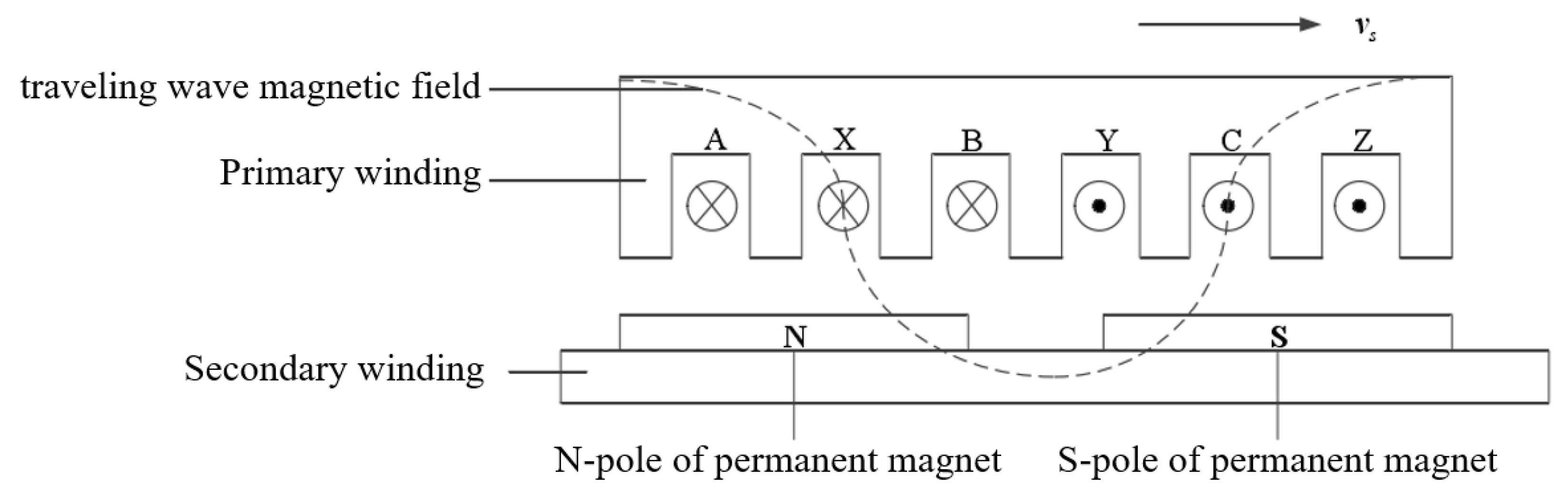
2.2. Operating Principles of PMLSM

2.2.1. Ripple Force

When an ideal, symmetrical, sinusoidal three-phase current is applied to the primary winding, the motor can generate a constant thrust. However, since the output current is obtained through an inverter, it usually contains harmonic components. Additionally, mechanical processing and assembly errors can cause deviations in the spatial distribution of the primary winding from the ideal. This results in asymmetry in the three-phase currents, leading to current harmonics during motor operation. The resulting thrust ripples are known as ripple force disturbances. A detailed analysis of the ripple force is as follows.
Assuming a three-phase, two-pole, full-pitch, and infinitely long secondary PMLSM, the symmetric three-phase sinusoidal alternating current, taking the A-phase currunt i a as an example, is applied as follows:
i a = I m sin ( ω t + θ 0 ) i a = I m sin ( ω t + θ 0 2 π / 3 ) i a = I m sin ( ω t + θ 0 4 π / 3 )
where I m is the current amplitude (A), ω is the angular frequency of the current (rad/s), t is the time, and θ 0 is the initial phase angle of the A-phase current (rad).
Assuming the air gap magnetic flux density B ( x ) varies sinusoidally and the origin of the coordinates is assumed to be on the centerline of the magnetic pole, we have:
B ( x ) = B m cos ( π x / p )
where B m represents the maximum value of the air gap magnetic flux density (T), p represents the pole pitch of the motor (m), and x represents the longitudinal absolute coordinate in the air gap of the motor (m).
Let the initial position of the A-phase coil be X 0 , and its spatial displacement at time t be x t . The spatial positions of the B-phase and C-phase coils are x t + X 0 + 2 p / 3 and x t + X 0 + 4 p / 3 , respectively. The back electromotive force (EMF) e a of the A-phase coil is given by:
e a = t x t + X 0 p / 2 x t + X 0 + p / 2 n B m cos ( π x / p ) l d x + n L a + M a b + M a c i a = E m a + E L a
where E m a is the no-load back EMF of phase A (V), E L a is the back EMF generated by armature reaction (V), n is the number of turns of the A-phase coil, l is the length of mover (m), L a is the inductance of the A-phase coil (H), M a b is the mutual inductance between the A-phase and B-phase coils (H), and M a c is the mutual inductance between the A-phase and C-phase coils (H).
Therefore:
E m a = E m sin π ( x t + X 0 ) / p E L a = K L a i a E m = 2 n B m l ( d x t / d t ) = 2 n B m l V
where K L a = n ( L a + M a b + M a c ) and V is the speed of mover. In an ideal situation, K L a = K L b = K L c .
Similarly, we have the following equations for the B-phase and C-phase:
e b = E m b + E L b e c = E m c + E L c
where E m b , E m c , and E m a have equal amplitudes, with phases lagging E m a by 2 π / 3 and 4 π / 3 , respectively. E L b , E L c , and E L a have equal amplitudes, with phases lagging E L a by 2 π / 3 and 4 π / 3 , respectively.
The speed of mover is V, and assuming the following two conditions hold:
V = d x t d t = p π ω θ 0 = π p X 0
Then, the thrust force F of the PMLSM is given by:
F = e a i a + e b i b + e c i c / V = e m a i a + e m b i b + e m c i c / V
From the above equation, we obtain:
F = 3 n l B m l m = K m I m
where K m = 3 n l B m is a constant motor thrust coefficient.
In reality, due to the nonideal sinusoidal waveforms of the current of mover and primary back EMF, fluctuations in the thrust coefficient occur, known as ripple disturbance phenomenon. Additionally, the three-phase windings of the motor are typically star-connected without a neutral line, and hence, there are no third harmonic components. Assuming the initial phase angle of the A-phase current θ 0 = 0 , the A-phase current can be expressed as:
i a ( t ) = I m sin ( ω t ) + I m 5 sin ( 5 ω t ) + I m 7 sin ( 7 ω t ) +
Additionally, the i b ( t ) and i c ( t ) are approximately similar to i a ( t ) , but i b ( t ) and i c ( t ) lag behind i a ( t ) by 2 π / 3 and 4 π / 3 , respectively.
The no-load back EMF of A-phase is as follows:
E m a ( t ) = E m 1 sin ( ω t ) + E m 3 sin ( 3 ω t ) + E m 5 sin ( 5 ω t ) +
Similarly, we have E m b ( t ) and E m c ( t ) , but E m b ( t ) and E m c ( t ) lag behind E m a ( t ) by 2 π / 3 and 4 π / 3 , respectively. Therefore, the thrust of PMLSM is:
F = e a i a + e b i b + e c i c / V = 3 π 2 p ω F 0 + F 6 cos ( 6 ω ) + F 12 cos ( 12 ω ) + F 18 cos ( 18 ω ) +
where F 0 is the average thrust of the motor and F 6 ( n 1 ) is the amplitude of the ripple force of the motor. Therefore, to reduce the impact of motor ripple force, it is necessary to maximize F 0 as much as possible and minimize F 6 ( n 1 ).

2.2.2. Cogging Force

Due to the unique slotted structure of the mover cores in PMLSMs, the magnetic field of PMs exerts uneven forces on both sides of the cogging. Consequently, when the mover is in motion, it experiences a pulsating perturbative force known as the cogging force, as illustrated in Figure 3:
(1)
When the cogging of the mover moves over the primary winding, there are moments when the cogging is precisely above the single-pole magnetic steel of the primary winding, as shown in Figure 3a. At this point, the magnetic field of the permanent magnet exerts equal forces on both sides of the cogging, so the movement of the motor is not affected by external forces.
(2)
At other moments, the cogging of mover moves over the gaps between the magnetic steel of the primary winding, as shown in Figure 3b. At this point, the forces exerted by PMs on the cogging are unequal on both sides, meaning that the motor experiences cogging force, which affects the operational accuracy of the motor.
Based on the above analysis, it can be seen that the cogging force is a perturbative force dependent on the positional relationship between the mover and the stator. Regardless of whether current flows in the circuit, the iron core will always be influenced by the permanent magnets. Therefore, the cogging force exists at any moment and any position within the motor system.
The cogging force d F c o g ( N ) can be represented by the following formula:
d F c o g ( N ) = i = 1 d F c o g i s i n ( i N c θ e )
where d F c o g i represents the amplitude of the i-th harmonic cogging force, N c denotes the least common multiple of the number of cogging slots and the number of pole pairs in the motor, and θ e represents the electrical angle.
From Equation (13), we can see that the cogging force of motor is independent of the current flowing in the circuit. Even if the circuit is not energized, the cogging force still exists.

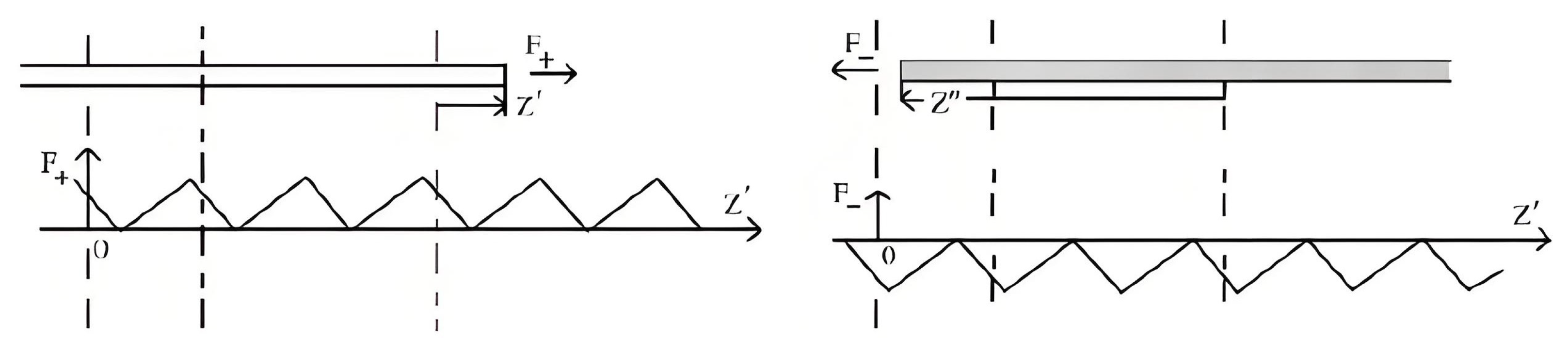
2.2.3. Analysis of the End Force

Since a linear motor is finitely long, it inevitably has structurally discontinuous ends. Similar to cogging force, the iron core at the ends is subjected to external perturbative forces caused by uneven magnetic flux, as illustrated in Figure 4. In a PMLSM, the primary core is linear and open at both ends, causing magnetic field distortions at the ends of the core. The magnetic flux generated by PMs does not enter the primary core along the normal direction entirely, resulting in a tangential component. Additionally, the amount of magnetic flux entering the primary core at both ends is uneven. This imbalance in the forces at the ends of the primary core affects the positioning accuracy of motor, leading to vibrations and noise. This phenomenon is known as the end force.
Similar to the cogging force caused by uneven magnetic flux, the end effect is a perturbative force that depends solely on the position of motor and structural parameters, independent of current as well. Through theoretical derivation, when the length of the mover’s iron core exceeds 2–3 pole pitches, the forces on both ends of the iron core can be considered independent of each other, meaning that the coupling of forces at both ends does not need to be considered. In this case, the end forces can be simply described as the sum of each force at two ends F + and F . Therefore, we have managed to calculate the forces at each end separately and then sum them up.
According to the single-end force experienced by the motor as shown in Figure 5, the following expression is given:
F | z = z = F + | z = z
where F and F + are equal in magnitude and opposite in direction at symmetrical positions and z denotes any position on the stator at the single end.
For any mover, the single-end effect force of the linear motor can be obtained through an appropriate displacement Δ . The relationship between them is given by the following equation:
F | z = z = F + | z = ( z + Δ ) Δ = L + i τ
where i is an arbitrary integer representing the number of pole pitches the core spans, L is the length of the core, and τ is the pole pitch.
Using Fourier series expansion, the end forces F and F + are given by:
F + = F 0 + n = 1 F s n sin 2 n π τ z + n = 1 F c n cos 2 n π τ z F = F 0 + n = 1 F s n sin 2 n π τ ( z + Δ ) + n = 1 F c n cos 2 n π τ ( z + Δ )
The end force F, therefore, can be obtained as follows:
F = F + + F = n = 1 F n sin 2 n π τ ( z + τ 2 )
As can be seen from the above equations, the end force is only related to the positions of the primary and secondary windings of the motor and exists at any moment in the system, regardless of whether the circuit is energized.
The cogging force and the end force of PMSLMs are collectively referred to as the detent force (DF), which is caused by fluctuations in the magnetic energy stored in the air gap at different moving positions. This force always attempts to fix the core in certain positions. Notably, research has shown that the end force is the main component of DF, and effective strategies to mitigate the DF are provided in the following sections.

3. Structural Optimization Methods for PMLSM

3.1. Adjusting the Shape and Length of the Mover or Stator

Based on the analysis of the causes of thrust fluctuations in the previous section, it is a natural approach to optimize the thrust ripple of a PMLSM from the perspective of structural design. Generally, this can be categorized into four optimization strategies. The first method involves adjusting the shape and length of the mover or stator, which can effectively reduce end effects, given that end effects are the main component of DF in PMLSM.
By adjusting the length and shape of the mover and stator cores of PMLSM, it is possible to regulate the phase difference between the two ends, which is considered an effective passive compensation method. Ref. [35] proposes a method to minimize the DF by adjusting the stator length using finite element analysis (FEA). Since the DF of the entire stator core is the sum of the two magnetic forces generated at both sides of the stator core, calculating the phase difference between these two magnetic forces and adjusting the stator length to cancel each other out can achieve the goal of reducing thrust ripple.
The study presented in Reference [36] highlights that designing an optimally sufficient moving core length, which ensures that the magnetic energy stored in the air gap remains nearly invariant with the position of the moving core, can effectively eliminate DF fluctuations to near zero. The paper introduces an ideal moving core design method, specifically by employing a grid-level ON/OFF topology approach to manage the topology of the mover. Furthermore, a metaheuristic optimization algorithm is utilized to perform numerical calculations on the topology shaping results. The simplified procedural steps of this method are illustrated in Figure 6. Experimental results demonstrate that this method can achieve an 89 % reduction in DF suppression without affecting the average output thrust, providing a new approach for PMLSM design.
PMLSMs possess excellent servo performance and dynamic characteristics; meanwhile, the high cost due to the extensive use of permanent magnets in the stator is a significant issue. Ref. [37] proposes a novel doubly salient permanent magnet (PM) linear synchronous machine (DSPMLSM), the arrangement of which is shown in Figure 7, with each mover composed of three phase segments spaced 60 electrical degrees apart. In DSPMLSM, the stator adopts a consequent pole structure, meaning the PMs have only one polarity. By adjusting the phase difference between each tooth, the overall force ripple can be reduced. The experiment has shown that DSPMLSM achieves a comparable output coefficient to traditional PMLSMs with reduced thrust ripple disturbance. Additionally, it uses fewer permanent magnets, thus lowering costs, making DSPMLSM a widely researched and applied PMLSM structure currently.
Building on the work of Ref. [37], Ref. [38] proposes a geometric optimization method that combines a multi-response surface method with two-dimensional finite element analysis based on the DSPMLSM structure. This comprehensive approach covers the design, optimization, prototyping, experimental validation, and servo performance evaluation of DSPMLSMs. It represents a practical engineering method for applying DSPMLSMs in production. Figure 8 shows the static thrust test setup used in the literature.
Ref. [39] presents a structural design scheme for the arrangement of mover teeth to reduce DF, thereby decreasing speed pulsation during low-speed operation and improving the operating accuracy of the PMLSM. The proposed geometric shape of DSPMLSM rearranges six teeth compared to the traditional double-sided core PMLSM. The mover is divided into three parts, resulting in the secondary part generating only slotting force without end force.
To minimize DF in DSPMLSM, Ref. [40] employs a new 2D optimization method for stepped-end-frame structures in slotless stators to reduce end effect forces. By utilizing destructive interference of slot phase shifts between the upper and lower stators, the cogging force is minimized.
In response to the requirements of electromagnetic launch systems, Reference [41] designed a new low-cost PMLSM, which adopts a dual-core sandwich structure. The stator uses a consequent poles structure, while the mover consists of two slotted iron cores and an additional moving PM sandwiched between them. This new PMLSM achieves the same output coefficient as traditional PMLSMs but with lower costs and smaller thrust fluctuations, making it a valuable design solution for electromagnetic launch systems.
Adjusting the length and shape of the stator and mover in PMLSMs is a straightforward and effective strategy, but it increases the complexity of the motor structure and manufacturing costs.

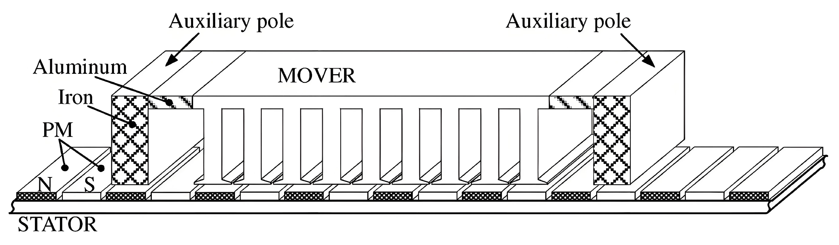
3.2. Adding Auxiliary Structures

Optimizing teeth shape design and coupling methods, as well as adding auxiliary structures, are effective ways to reduce thrust fluctuations in PMLSMs. As an active compensation method, Reference [42] specifically designed an auxiliary poles structure that can effectively suppress the end effects in DF. By using a 2D finite element analysis method, the optimal height, length, and position of the auxiliary rods that minimize end effects were determined. As shown in Figure 9, two auxiliary poles are symmetrically fixed at both ends of the iron core, generating equal and opposite forces. These forces compensate for the end forces, minimizing them and ensuring that the total force is zero.
Building on the work in [42], Reference [43] studied an improved optimization method for auxiliary pole structures. This method replaces rectangular poles with convex poles and specifically employs a combination of orthogonal optimization and finite element methods to determine the design parameters of the auxiliary poles, which yields faster and more detailed optimization results.
Reference [44] designed a PMLSM with a staggered arrangement of PMs. This structure significantly reduces the thrust fluctuations in linear motors, while it causes a reduction in the average thrust. Addressing this issue has become a focus of many subsequent research papers.
Reference [45] developed a new structure of DSPMLSM, which also adopts a staggered arrangement. In this design, the subsequent components are shifted by a distance of τ /2, and the windings are rearranged. This method can effectively overcome the significant end effect disadvantage of linear motors while ensuring that the average thrust does not decrease compared to traditional staggered structures.
Similarly, to address the issue of reduced average thrust caused by staggered structures, Reference [46] proposed a structure with two base pieces staggered and winding rearrangement. It optimized specific geometric parameters through FEA to minimize thrust fluctuations while maintaining the output coefficient of motors unchanged.
Reference [47] proposed a V-shaped tooth-slot structure to suppress and reduce DF in PMLSMs, as shown in Figure 10. Correspondingly, the coil structure is also changed from rectangular to V-shaped coils meeting the same angle as the V-shaped tooth slot. Meanwhile, the specific slots design is implemented using the infinitesimal method. Finite element simulations demonstrate that V-shaped tooth slot motors exhibit higher average thrust and smaller thrust fluctuations.
Reference [48] proposed a motor structure with fine teeth, narrow slots, and a high aspect ratio to address vibrations and noise caused by high-frequency ripple forces in PMLSMs. The design incorporates a moving skewed Halbach magnet array. Compared to traditional PMLSMs, this design achieves a 95 % reduction in noise while maintaining motor performance.
Ropeless elevator systems are common applications of PMLSMs. Traditional PMLSMs face challenges such as high material usage and costs associated with PMs. Reference [49] introduced a novel Halbach consequent-pole (HCP) PMLSM structure. As depicted in Figure 11, in the Halbach array, tangential and radial segments of PMs are assembled to enhance the magnetic field, thereby enhancing the magnetic flux density in the air gap and reducing the amount of permanent magnet material required.
Similarly addressing ropeless elevator systems, Reference [50] optimized the structure and conducted magnetic analysis of a double-sided long-stator PMLSM model for elevator applications. By employing a combined approach of FEA and response surface methodology, it adjusted the length of the synchronous motor, the displacement length of motor groups, and slot lengths to optimize the design of the PMLSM structure.
Adding auxiliary structures such as semi-arched auxiliary teeth [51] and arc-shaped auxiliary teeth [52] to suppress motor thrust fluctuations is highly effective. However, the shape parameters of auxiliary teeth are typically challenging to determine accurately, increasing manufacturing difficulty. Additionally, these auxiliary structures increase the overall length and weight of the motor.

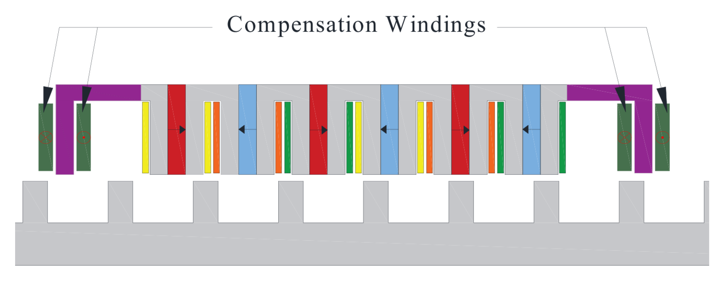
3.3. Additional Compensation Windings
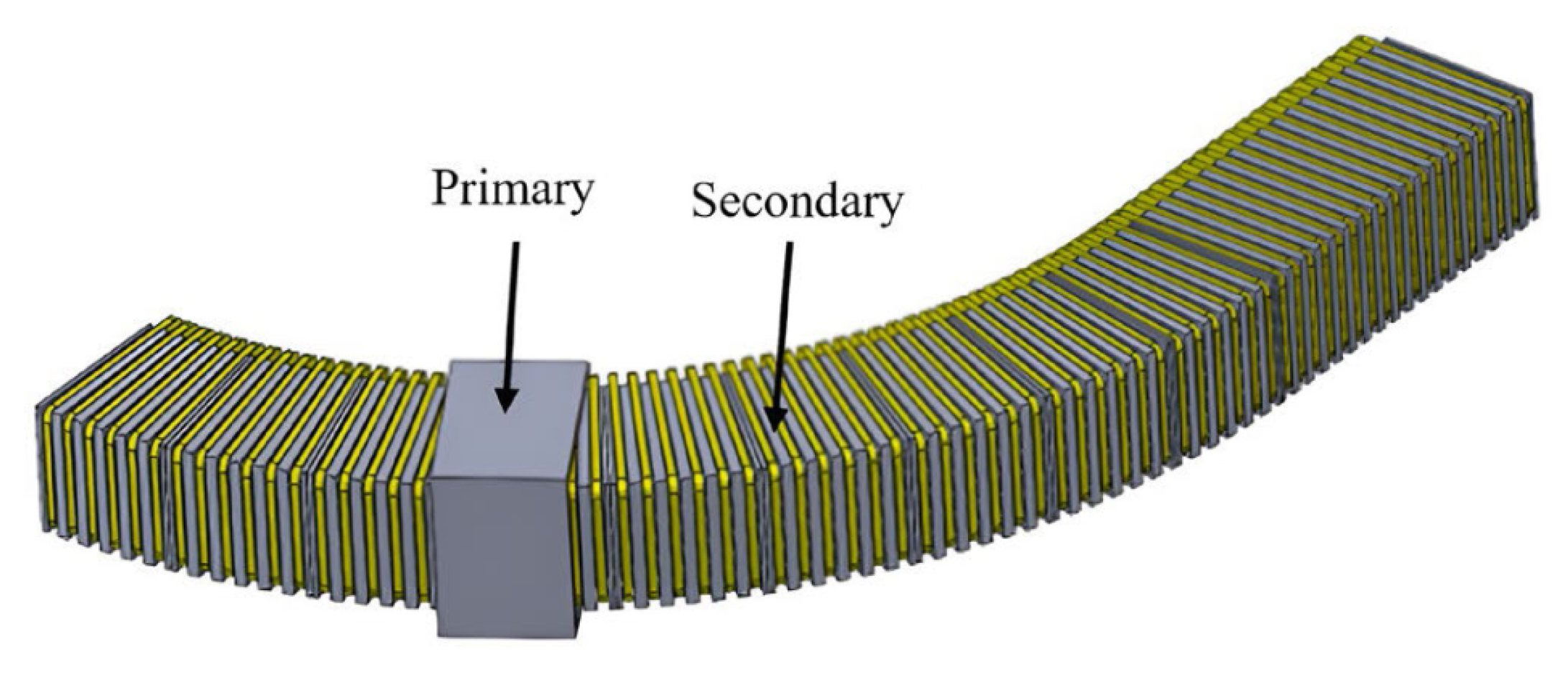
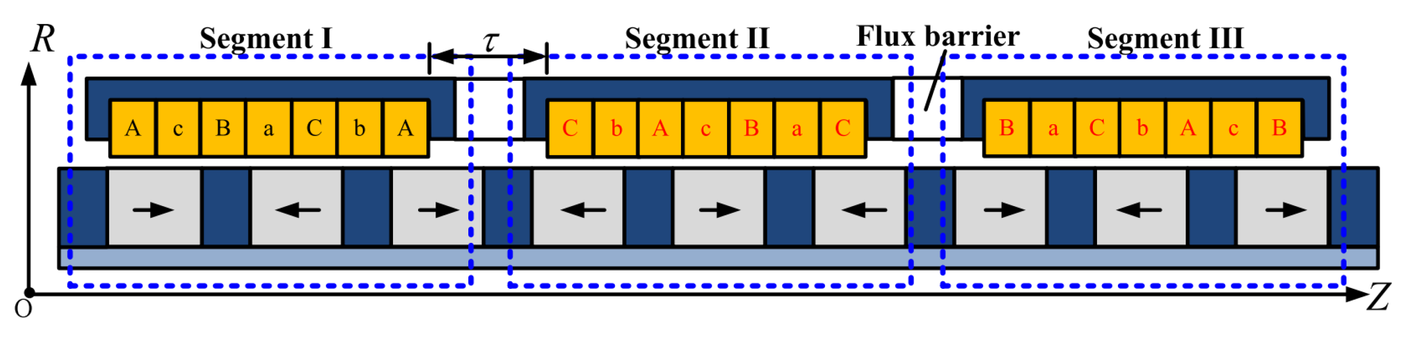
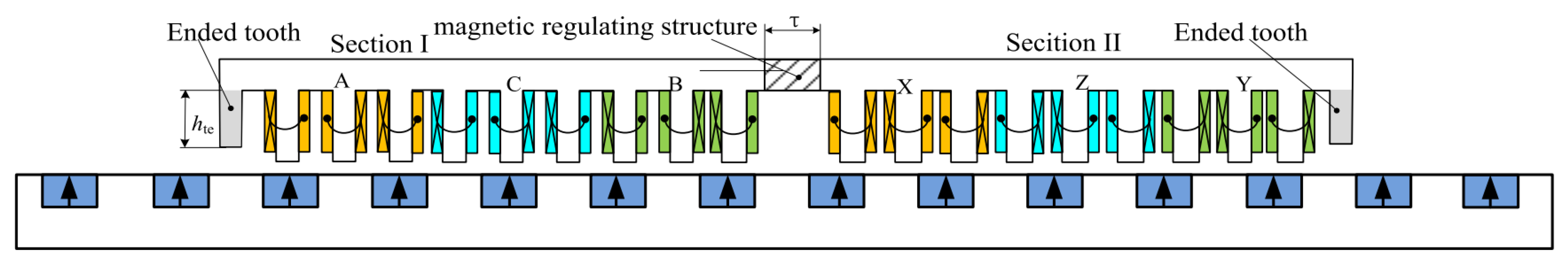
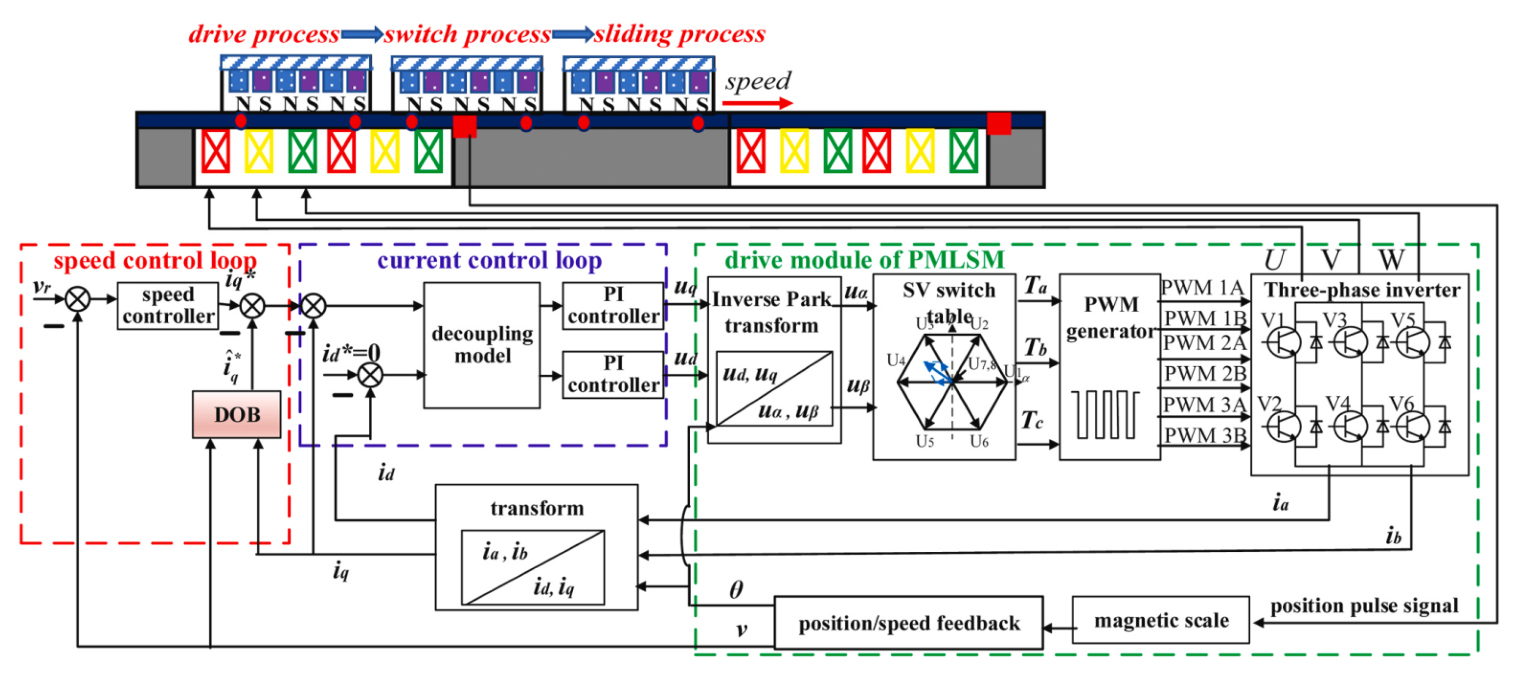
A third active compensation method involves introducing additional compensation windings based on the motor windings and applying compensation currents to generate force fluctuations opposite to the components of DF, thereby suppressing periodic thrust fluctuations in PMLSMs.
Reference [53] developed a primary side flux-switching permanent magnet linear motor (FSPMLSM) equipped with an independent magnetic circuit compensation module. By adjusting the position of the primary tooth ends and surrounding them with compensation windings, compensation current was applied to counteract motor thrust fluctuations, which is depicted in Figure 12. The relationship between compensation force and compensation current was linear, allowing for the derivation and analysis of the appropriate compensation current required by the system. Additionally, the innovative independent magnetic circuit design of the FSPMLSM prevented magnetic coupling between compensation windings and motor windings, thereby avoiding unintended back EMF distortions. Experimental results demonstrated a 67 % reduction in the peak value of DF using this method.
In response to the cogging force involved in widely applied double-sided permanent magnet synchronous linear motors (DSPMLSM), Reference [54] proposed a novel reversed slots structure, which effectively reduces motor thrust fluctuations but simultaneously causes unbalanced back EMF. To address this issue, the paper introduced two novel compensation windings on top of the traditional motor structure to compensate for the unbalanced back EMF. It also presented a prototype of an 8-pole 9-slot DSPMLSM, which demonstrated through simulation and experimentation the effectiveness of the counter-slot structure and compensation windings.
Reference [55] presents a novel double-primaries tubular permanent magnet synchronous linear motor (DPTPMSLM) with a structure composed of two primaries, a secondary and a flux barrier, which achieves low thrust ripple. Through the combination of motor pole-slots and the appropriate arrangement of windings, the electromagnetic characteristics of the two primary windings can be made to superimpose and offset each other, thus ensuring the suppression effect on the motor’s thrust ripple. Taking a 12-slot and 11-pole DP-TPMSLM as an example, the article establishes an experimental platform and verifies the favorable working performance of the proposed motor structure.
In reference [56], the authors proposed a multi-sided permanent magnet linear synchronous motor (MSPMLSM) with Ring Structure Winding, as shown in Figure 13. After optimization of the MSPMLSM structure parameters, it can achieve a thrust of 419.5 N while the thrust ripple of the motor system is reduced to 4.5 % , which develops excellent output performance.
In addition, reference [57] presented an innovative C-shaped winding PMLSM that ensures a relatively small thrust ripple when the motor system operates at high speed and with a large thrust. The experiment established in this paper has verified that the thrust ripple of the proposed PMLSM is reduced to 0.8 % .

3.4. Modular Design

Finally, to mitigate mainly the effects of end forces, modular design methods employ dispersed distribution of permanent magnets and increase the number of ends to balance out the end forces, thereby achieving a reduction in overall thrust fluctuations.
Reference [58] proposed a method to eliminate thrust fluctuations in linear motors by increasing the number of ends, which leads to a modular primary iron-core permanent magnet synchronous linear motor (MPI-PMLSM). Unlike traditional linear motors, the primary cores of MPI-PMLSM are dispersed, with each tooth having an end. This approach uses slotting techniques to counteract and compensate for mutual DF, thereby reducing overall thrust fluctuations in the motor system and effectively suppressing disturbances. Moreover, this dispersed primary structure design allows for more flexibility in motor size design. Modular design methods like these are widely employed for optimizing PMLSM structures.
Building upon Reference [58], Reference [59] employed a three-segment modular structure for the primary component of the motor, increasing the number of ends from 2 to 6, as shown in Figure 14. This structure effectively mitigates issues of unbalanced three-phase inductance, thereby reducing ripple forces in motor thrust fluctuations and enhancing the operational precision of the motor system.
Reference [60] similarly proposed a modular primary core structure for PMLSMs, utilizing inset-type permanent magnets that maintains stable ferromagnetism under high electrical loads, termed as a new linear hybrid excitation flux reversal (HEFR) motor. This linear motor structure enables adjustable air-gap flux and achieves lower thrust fluctuations at a reduced cost, promising favorable applications in long-stroke platforms.
The consequent-pole permanent magnet linear synchronous motor (CP-PMLSM) is widely used, and to study and optimize its thrust fluctuation characteristics, Reference [61] presented a two-step design method. Initially, modular design is employed to obtain a structured layout, as shown in Figure 15, followed by coil rewinding. This approach attenuates thrust fluctuations caused by current and voltage harmonics, leading to the optimization of the geometrical dimensions of motor end teeth and thereby reducing overall motor thrust fluctuations.
Reference [62] addressed the inflexibility and significant thrust fluctuations observed in PMLSMs due to load and stroke variations, proposing an optimization method for a dual-module structure of PMLSM. Configuration of multiple-unit-primary and multiple-unit-secondary can be flexibly decided, and with theoretical guidelines established to determine the optimal configuration for minimizing thrust fluctuations in the motor system.
Reference [63] presented an optimization method for DF in modular PMLSM (MPMLSM). Based on an 8-module, 6-slot, 5-pole MPMLSM structure, the experimental results confirm a 85.5 % reduction in peak DF for the motor system.
In ideal conditions, modular design achieves independent interactions between unit elements, effectively canceling thrust fluctuations among them to reduce overall thrust fluctuations. However, actual neighboring unit modules exhibit coupling effects that alter magnetic field distribution, increasing disturbance forces and impacting motor operational precision. Reference [64] conducted magnetic field analysis for modular PMLSM considering coupling effects, proposing methods to reduce motor system thrust fluctuations by adjusting magnetic flux barrier lengths. This research provides crucial guidance for optimizing modular PMLSM designs.
Modular optimization methods are currently widely used strategies for optimizing PMLSM structures. They can be combined with other optimization methods to effectively enhance the performance of PMLSMs.
Considering the structural optimization methods mentioned above, we perform a comparative analysis of the advantages and disadvantages of them, as illustrated in Table 1.
Structural design optimization strategies for reducing PMLSM thrust fluctuations are very effective but often involve complex design results, time-consuming finite element analysis, and high manufacturing costs. Additionally, these strategies increase the control difficulty during subsequent motor usage. To avoid and mitigate these issues, the next section will discuss how to optimize PMLSM thrust fluctuations through a control perspective.

4. Control Strategy for PMLSM

From the perspective of a control strategy for PMLSM, numerous results have been achieved in mitigating motor thrust ripple and improving operational performance. These methods offer design flexibility and ease of implementation. They can be classified based on different control loops, such as position loop control and current loop control, or according to different control objectives, such as compensation-based control and disturbance suppression-based control. This paper categorizes the methods based on different actual control approaches, including sliding mode control, fuzzy neural network control, robust control, iterative learning control, and so on.

4.1. Sliding-Mode Control

The concept of sliding mode control (SMC) involves using discontinuous nonlinear control signals to force the system to operate on a predetermined sliding surface, thereby achieving the desired operational goals. This method is robust and particularly suitable for nonlinear systems. Due to the inherent complexity and nonlinearity of PMLSM systems, SMC is widely applied in these systems for its simplicity of implementation, nice dynamic response, and suitability for nonlinear characteristics, including position control, current control, and speed control.
The specific design methodology of SMC primarily involves two steps: the first step is to design a sliding surface that exhibits the desired dynamic behavior, such as tracking accuracy and stability; the second step is to design a sliding mode control law that drives the state of system to reach the sliding surface and maintains it without deviation. This encapsulates the reachability and existence of the sliding mode control theory. It is noteworthy that the entire SMC design process is typically based on Lyapunov stability theory.
Ref. [65] proposed an intelligent-complementary sliding mode control (ICSMC) based on field-programmable gate array (FPGA), achieving precise trajectory tracking of PMLSM in servo control systems. Complementary SMC (CSMC) can mitigate the common chattering issue of SMC while ensuring control accuracy and robustness. The designed CSMC control law u is as follows:
u = u e q + u h i t
where u e q is the equivalent-control law and u h i t is a hitting-control law obtained as follows:
u e q = 1 B n d m ¨ A n d ˙ + λ 2 e ˙ + λ e + S
u h i t = 1 B n ρ S a t S + S C Φ
where B n = K f / M ¯ > 0 and A n = D ¯ / M ¯ , K f is the thrust coefficient, M ¯ is the total mass of the moving element system under nominal condition, D ¯ is the nominal viscous friction and ironloss coefficient, d is the actual command, d m is the desired command and d m ¨ is its two derivative, λ is a positive constant. and e = d m d is the tracking error. S a t is a saturation function designed to reduce the chattering phenomena, as defined follows:
S a t S + S C Φ = 1 , i f Φ S + S C S + S C Φ , i f Φ S + S C Φ 1 , i f S + S C Φ
where S is the generalizad-sliding surface, S C is a second sliding surface, and Φ is the thickness of the boundary layer.
The intelligent CSMC (ICSMC) utilizes a radial basis function network (RBFN) estimator to further enhance the tracking performance of the system, building upon the foundation of CSMC. The control algorithms mentioned above were implemented on an FPGA chip and the digital circuit for the intelligent control system based on the FPGA chip was designed. Experimental results have demonstrated the effectiveness of the proposed control methods.
Similarly addressing the position tracking problem of PMLSM, Ref. [66] employed an adaptive fuzzy fractional-order sliding-mode control (AFFSMC) strategy. Initially, a fractional-order integral sliding surface is selected for SMC, which presents the challenge of determining the hitting control gain. To resolve the gain selection issue and suppress chattering, the authors combined an adaptive fuzzy tuning strategy with an online uncertainty observation tool, resulting in the AFFSMC control method.
To improve the position tracking accuracy and robustness of PMLSM systems under uncertainties such as thrust fluctuation disturbances and parameter variations, Ref. [67] proposed a super-twisting nonsingular terminal sliding mode control (STNTSMC) method based on a high-order sliding mode observer. Terminal sliding mode control (TSMC), compared to traditional sliding mode control, offers faster convergence due to its dynamically nonlinear sliding surface but is prone to singularities, causing singularity issues. The nonsingular terminal sliding mode control (NTSMC) addresses this problem by changing the switching control law purposefully. Furthermore, building upon NTSMC, a novel super-twisting algorithm and a high-order sliding mode observer are introduced. The resulting STNTSMC control law is as follows:
u = u e q + u s t w
where u e q is the equivalent-control law and u s t w is the switching control law defined as follows:
u e q = 1 B n A n d ˙ + d m ¨ c 1 e 1 ˙ A
u s t w = 1 B n k 1 s 1 2 s i g n ( s ) k 2 s 0 t k 3 s i g n ( s ) d τ 0 t k 4 s d τ
A = c 2 e x p λ t e 1 2 β [ ( 1 2 β ) e 1 ˙ λ e 1 ]
where B n = K f / M and A n = B / M , K f is the electromagnetic thrust coefficient, M is the total mass of the mover, B is the viscous friction coefficient, d is the actual mover position and d m is the desired mover position, e 1 = d ( t ) d m ( t ) is the tracking error, c 1 , c 2 , and λ are positive constants, 0 < β < 1 , s is the nonlinear sliding surface, and k 1 , k 2 , k 3 , and k 4 are gains.
When appropriate parameters k 1 , k 2 , k 3 , and k 4 are chosen to satisfy s = s ˙ = 0 , the error e 1 can converge to zero. Experimental validation shows that STNTSMC can effectively mitigate the chattering phenomenon in PMLSM systems and improve robustness.
Ref. [68] proposed a robust adaptive nonsingular fast integral terminal sliding mode control (ANFITSMC) strategy, which can effectively mitigate the decline in operational accuracy caused by motor thrust fluctuations and other unknown uncertainties. Integral terminal sliding mode control (ITSMC) can achieve faster convergence within a finite time, and when combined with adaptive algorithms, it can enable real-time updates of controller parameters to enhance control system performance.
Ref. [69] proposed a discrete adaptive sliding mode controller (DASMC), which combines the advantages of online parameter updates through adaptive algorithms and the fast response and robustness of sliding mode control. The design criteria for the sliding surface in the discrete domain are provided as follows:
S ( k ) = Λ ( z 1 ) E ( k ) = 0
where Λ ( z 1 ) is the stable polynomial matrix and E ( k ) is the error state.
The adaptive sliding mode control law is designed as follows:
Δ U k = B 0 1 ϕ T k θ ^ k + Λ z 1 Y m * k + 1
where B 0 is a known nonzero constant and Y m * ( k + 1 ) is the reference input at k + 1 point. ϕ ( k ) and parameter estimation θ ^ are defined as follows:
ϕ ( k ) = [ Y m ( k ) Y m ( k 1 ) Y m ( k 2 ) Δ U ( k 1 ) Δ U ( k 2 ) ] T
θ ^ k = θ ^ k 1 + δ ( k ) α ϕ n ( k 1 ) S n ( k )
where Y m ( k ) is the output variable, 0 < α < 2 ( 1 γ 1 ) , ϕ n ( k ) = ϕ ( k ) / n ( k ) , and S n ( k ) = S ( k ) / n ( k 1 ) are normalized signals, n ( k ) is given by n ( k ) = max ( ϕ ( k ) , 1 ) , and δ ( k ) is defined as follows:
δ ( k ) = 1 , if S ( k ) γ ε , 1 < γ < 0 , otherwise .
where ε is the upper bound of the system disturbance variation.
Unlike the previous studies above, Ref. [70] proposed a high-performance control strategy for the current loop of PMLSM based on a predictive current controller (PCC). To address the disturbances caused by thrust fluctuations and parameter variations, an improved variable exponential reaching law sliding mode algorithm is introduced specifically, i.e., the thrust ripple sliding mode observers (TRSMO) and parameter disturbance sliding mode observers (PDSMO), respectively.
Numerous results based on the sliding mode control of PMLSM have been achieved; Ref. [71] provides a more targeted and detailed review of these.

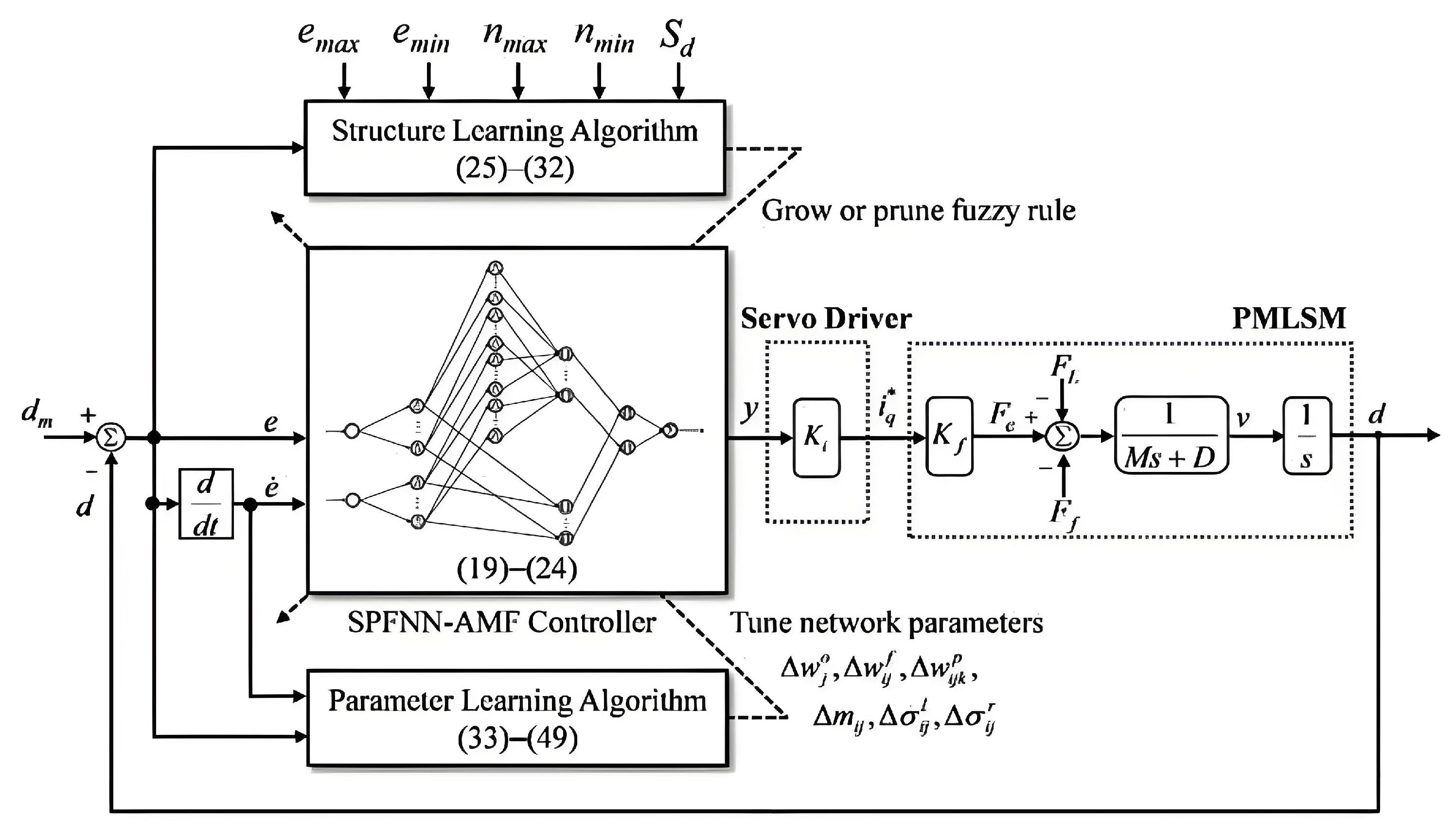
4.2. Fuzzy Neural Network Control

The fuzzy neural network control method combines fuzzy theory and neural networks, serving as an intelligent control method with powerful self-learning capabilities and nonlinear mapping abilities, making it highly suitable for complex nonlinear systems such as PMLSMs. Scholars in related fields have also contributed numerous valuable findings worthy of study and research.
Reference [72] proposed a recursive fuzzy neural network (RFNN) controller design method based on classical fuzzy neural networks for application in PMSLM systems. Specifically, the RFNN was utilized to perform online gain tuning for the feedback proportional-integral (PI) controller, aiming to achieve high-precision and robust position control of the PMSLM system under thrust ripple disturbances.
The RFNN integrates the advantages of dynamic recurrent neural networks and fuzzy control, possessing excellent dynamic properties and the ability to store information, as well as the fuzzy reasoning capabilities to handle uncertain factors effectively. In Ref. [73], a self-constructing recurrent fuzzy neural network (SCRFNN) control method based on RFNN is also proposed, achieving high-precision position control for PMLSM systems.
In Ref. [74], a self-evolving probabilistic fuzzy neural network controller with asymmetric membership functions (SPFNN-AMF) is proposed. This controller combines the advantages of self-evolving neural networks, probabilistic fuzzy (PF) logic systems, and asymmetric membership functions (AMF) to achieve precise control of PMLSM systems under thrust ripple disturbances. Integrating probabilistic information into (FNN) enhances the ability to handle random uncertainties, resulting in a probabilistic FNN (PFNN). The self-evolving approach further improves the learning capabilities of the FNN. Additionally, the design of AMF enhances the ability of SPFNN to manage both random and nonrandom uncertainties. The article presents neural network parameters updating methods based on the structure learning algorithm (SLA) and the parameter learning algorithm (PLA). Figure 16 illustrates the system control structure diagram based on the SLA algorithm.
In Ref. [75], an adaptive fuzzy neural network (AFNN) is proposed, which updates the FNN parameters online through an adaptive algorithm. A robust compensator is introduced in the feedback loop to overcome approximation errors caused by finite membership functions, thrust ripple, friction, and other disturbances.
Building on the traditional AFNN, Ref. [76] proposed a self-adaptive interval type-2 neural fuzzy network (SAIT2NFN) for controlling the PMSLM servo system. The system control block diagram is shown in Figure 17, where the SAIT2NFN functions as a controller in both the feedback and feedforward loops. The feedforward SAIT2NFN controller compensates for uncertainties in PMSLM system, including thrust ripple and noise, by using interval type-2 fuzzy sets. The feedback SAIT2NFN controller, combined with a Kalman filtering algorithm, forms a robust SAIT2NFN inverse system capable of achieving stable control of the PMLSM system in changing environments.
In Ref. [77], a fuzzy neural network (FNN) controller based on a recurrent radial basis function network (RBFN) is proposed. The RBFN-based FNN combines the advantages of the self-constructing fuzzy neural network (SCFNN) and recurrent neural network (RNN), allowing for simultaneous structure learning and parameter learning with rapid online updates.
In Ref. [78], a recurrent fuzzy neural network (RFNN) control method based on a hybrid supervisory control system is proposed. The supervisory control is designed based on system uncertainties to ensure the robustness of the algorithm. On this basis, the intelligent control system adjusts and smooths the control force to avoid chattering issues.

4.3. Observer-Based Control

Observer-based methods are a widely used control strategy that enables the acquisition of system states and disturbances needed for optimization. Furthermore, by combining with specific control methods, the observed disturbances can be suppressed and compensated. In this subsection, we will discuss various observer-based control methods for addressing the thrust fluctuation disturbances in PMLSM systems.
In Ref. [79], a periodic adaptive disturbance observer (PADOB) is proposed to attenuate periodic disturbances in PMLSM systems, such as cogging forces. The system control algorithm consists of two main phases: the search phase and the learning phase. During the search phase, a rough feedforward and feedback controller based on nominal model is established, with the current disturbances being stored in the disturbance observer. In the learning phase, a periodic adaptive (PA) control law is used to update the feedforward and feedback parameters by observed disturbances before, which aims to minimize the tracking error of the PMLSM control system with thrust fluctuation disturbances.
Similarly, based on an adaptive disturbance observer, Ref. [80] addresses a multi-loop control strategy for long-stroke PMLSMs with discontinuous stators. The PMLSM structure and system control block diagram are shown in Figure 18, where the structure of discontinuous stator causes changes in thrust at different positions. The paper presents a closed-loop design for both the velocity loop and the current loop. In the velocity loop, a DOB with velocity and thrust feedback is used to suppress DF disturbances. Meanwhile, in the current loop, a control strategy combining dual PI controllers and a decoupling method is employed to compensate and suppress the ripple forces. Experimental results demonstrate the effective speed control accuracy and strong disturbance rejection capability.
In Ref. [81], a robust predictive current control strategy for PMLSMs based on a variable-gain adaptive disturbance observer is proposed. A predictive current control (PCC)-based mathematical model of the system can calculate reference voltages for future moments, with the high switching frequencies and minimal current ripple. However, PCC is sensitive to modeling accuracy and disturbances from model uncertainties. To address these drawbacks, an online adaptive gain updating method is introduced to enhance the robustness of PCC and improve the overall operational performance of PMLSM systems. The system control block diagram is illustrated in Figure 19.
In Ref. [82], an augmented generalized proportional-integral observer (GPIO) is proposed to estimate and compensate for disturbances such as thrust fluctuation in PMLAM systems. This approach also targets current loop control, utilizing deadbeat predictive current control (PCC). An augmented GPIO is developed to compensate for thrust fluctuation caused by significant parameter mismatches.
In Ref. [83], a high-precision motion control scheme for PMLSMs based on an iterative learning observer is proposed. The system control block diagram is shown in Figure 20. Specifically, a saturated constrained iterative learning controller is designed in the feedforward channel to estimate periodic uncertainties, which overcomes the disruptive effects of nonperiodic disturbances, ensuring the convergence and stability of system. In the feedback channel, a robust control design combined with a parameter adaptive strategy further enhances the operational accuracy of the PMLSM system under thrust fluctuation disturbances.
In Ref. [84], a proportional resonant (PR) thrust ripple suppression strategy based on an auxiliary model compensation resonant extended state observer (AMC-RESO) is proposed. The feedback controller PR can preliminarily suppress the main components of the thrust ripple, which is DF. Furthermore, the AMC-RESO is used to estimate and suppress the remaining thrust ripple, achieving comprehensive thrust ripple suppression in the PMLSM.

4.4. Others

In addition to the aforementioned three main types of control methods for thrust fluctuation in PMLSM systems, there are many other research achievements, though relatively fewer in number, which are introduced here collectively.
In Ref. [85], an iterative learning identification and compensation method for periodic thrust fluctuation in PMLSM systems with time delay is proposed. Specifically, the subspace projection method is utilized to obtain a clean thrust fluctuation error of system, which helps improve identification accuracy. The subspace is spanned by the basis functions selected from the PMLSM model and the thrust fluctuation model, compensating for the time delay in the system, as shown in following equation. Experiments demonstrate that this method has high identification accuracy and excellent position tracking performance:
H = s p a n d 2 r ¯ d t 2 , d r ¯ d t , sin ( ω 1 r ) , , cos ( ω 6 r )
where r is the reference input, r ¯ = r ( t + t d ) , t d is the system time delay, ω i ( i = 1 , 2 , . . . , 6 ) are π / τ , 2 π / τ , 4 π / τ , 6 π / τ , 3 π / 2 τ , and 9 π / 2 τ , respectively, and τ is the pole pitch.
In Ref. [86], an anticipatory lead fractional-order iterative learning control (ALFOILC) method is proposed to ensure position tracking accuracy of PMLSM systems under thrust fluctuation disturbances. Compared to traditional iterative learning control (ILC), fractional-order ILC (FOILC) compensates for phase lag, improving the learnable bandwidth of system. The anticipatory lead FOILC (ALFOILC) further mitigates the impact of thrust fluctuation and acceleration/deceleration on the operational accuracy of PMLSM systems.
In Ref. [87], a control method based on extremum robust domain characteristics (ERDC) is proposed to enhance the robustness of PMLSM systems in the presence of thrust fluctuation disturbances. The overall optimization process of the algorithm is shown in Figure 21. First, the niche particle swarm optimization (NPSO) method is used to obtain all extrema that satisfy the constraint conditions. Then, a robustness evaluation index is proposed based on the thrust fluctuation dispersion measure and the size of the extremum robust domain (ERD), leading to the identification of extrema that ensure optimal robustness.
In Ref. [88], an active disturbance rejection control method with a low-pass filter and a repetitive controller is proposed to eliminate thrust ripple in PMLSM systems. Compared to traditional active disturbance rejection control (ADRC), the RC-LPF-ADRC method enhances the ability to observe thrust ripple disturbances by employing a low-pass filter (LPF). Additionally, a repetitive controller (RC) is added in parallel with the disturbance rejection loop, further improving the tracking performance of system.
Ref. [89] proposed a control method combining a vector resonant controller and an active disturbance rejection controller (VR-ADRC), as shown in Figure 22. The vector proportional–integral controller G V P I , with the following expression, exhibits enhanced thrust fluctuation suppression capabilities. Moreover, by combining with ADRC, the disturbance rejection capability of the system is further improved:
G V P I = K p + K I s + K p r s 2 + K i r s s 2 + ω c s + ( ± ω n ) 2
where K p and K I are the proportional and integral parameters of the proportion integral (PI) controller, K p r and K i r are the parameters of the improved resonant (VR) controller, ω n is the resonant frequency to be adjusted, and ω c is the bandwidth of the resonant point.
Model predictive thrust control (MPTC) has the advantage of multi-objective optimization, such as achieving high dynamics, low power loss, and thrust fluctuation suppression. However, finding suitable weighting factors for MPTC design is a challenging. In Ref. [90], two methods for designing weighting factors for PMSLM systems are proposed. The first method involves replacing the flux control term with a flux fluctuation constraint, and the second method converts flux and thrust terms with different units into the same thrust units. Both of these methods avoid the complex process of adjusting weight factors.
Obtaining the impedance frequency response can help us to obtain the imbalance information and design the filter or control strategy. Reference [91] has proposed an improved method for motor impedance measurement, which expands the measurable frequency spectrum from low frequencies to high frequencies, with the highest frequency reaching up to 120 MHz.
Considering the control strategies mentioned above, we perform a comparative analysis of the advantages and disadvantages of them, as illustrated in Table 2.

5. Discussion

This paper analyzes and discusses numerous methods for suppressing thrust ripple in the PMLSM, which are mainly divided into two categories: structural optimization and control strategies. Regarding how to choose appropriate methods during the design, use and operation of the motors, we conduct a comparative discussion on these two categories of methods from aspects including economic and time consumption, application difficulty, and stability, as illustrated in Table 3.
As a mature actuator that has been widely used for a long time, the PMLSM has witnessed a vast number of achievements in suppressing thrust ripple. In order to further enhance the performance of PMLSM, we anticipate the application of new materials such as high-performance permanent magnets, new manufacturing technologies like 3D printing, and higher computing power of computers such as large AI models. Meanwhile, digital twin can become a research direction in the future, which can enable rapid verification and optimization of various control strategies in a virtual environment and can monitor the operating status of PMLSM in real time. However, it also requires a high level of precision in modeling PMLSM and ensuring the synchronization of data. These new materials and new technologies offer more possibilities and more effective solutions for suppressing thrust ripple in PMLSM, and thus, they are the future research directions.

6. Conclusions

Due to the characteristic of “zero transmission”, PMLSM achieve high dynamic and high precision, so that it has been widely used in industrial production. However, because of its own mechanical structure and operating principles, PMLSM is subject to significant thrust ripple, which severely impact the operational accuracy, including cogging force, end force, and ripple force.
The methods to mitigate the thrust ripple in PMLSMs can be mainly divided into two categories: optimizing the motor structure or adopting advanced control strategies. Structural optimization methods include adjusting the length and shape of the rotor and stator cores, adding auxiliary structures, rearranging the slots, incorporating compensation windings to directly counteract disturbance forces in the PMLSM system, or modularizing the rotor and stator designs to achieve overall thrust fluctuation attenuation through mutual disturbance force cancellation. There are numerous achievements in suppressing the thrust ripple using control strategies for PMLSM systems. Given the strong nonlinearity and high complexity of PMLSM systems, this paper discusses sliding mode control, fuzzy neural network control, observer-based control, iterative learning control, active disturbance rejection control, robust control, model predictive control, etc.
While structural optimization methods for PMLSMs are effective, they are often time-consuming and costly, and increase structural complexity, making them challenging to implement in practical industrial production. In contrast, compensating for thrust fluctuations from a control perspective is generally more feasible and flexible. However, the upper limit of control accuracy in PMLSM systems is constrained by the structure. Therefore, in future research and practical industrial production, combining structural optimization with control strategies will be the main approach to suppress the thrust ripple in PMLSM and improve the operational accuracy of system.

Author Contributions

Investigation, S.C.; Writing—original draft, S.C.; Writing—review and editing, Y.L.; Conceptualization, Y.L.; Validation, Q.Z.; Supervision, J.T. All authors have read and agreed to the published version of the manuscript.

Funding

This work is supported by the National Natural Science Foundation of China under Grant 52075132.

Data Availability Statement

No new data were created or analyzed in this study. Data sharing is not applicable to this article.

Conflicts of Interest

The authors declare no conflicts of interest.

References

  1. Bramerdorfer, G.; Tapia, J.A.; Pyrhonen, J.J.; Cavagnino, A. Modern electrical machine design optimization: Techniques, trends, and best practices. IEEE Trans. Ind. Electron. 2018, 65, 7672–7684. [Google Scholar] [CrossRef]
  2. Eguren, I.; Almandoz, G.; Egea, A.; Ugalde, G.; Escalada, A.J. Linear Machines for Long Stroke Applications-A Review. IEEE Access 2020, 9, 3960–3979. [Google Scholar] [CrossRef]
  3. Wang, X.Z.; Chen, F.X.; Zhu, R.F.; Huang, X.L.; Sang, N.; Yang, G.L.; Zhang, C. A Review on Disturbance Analysis and Suppression for Permanent Magnet Linear Synchronous Motor. Actuators 2021, 10, 77. [Google Scholar] [CrossRef]
  4. Lin, F.J.; Shen, P.H. Robust Fuzzy Neural Network Sliding-Mode Control for Two-Axis Motion Control System. IEEE Trans. Ind. Electron. 2006, 53, 1209–1225. [Google Scholar] [CrossRef]
  5. Kang, K.; Wang, M.Y.; Sun, J.X.; Zhang, C.M.; Li, L.Y. Nonlinear Friction Compensation for PMLSM Using an Enhanced Adaptive Friction Observer. IEEE Trans. Ind. Electron. 2024, 71, 16234–16244. [Google Scholar] [CrossRef]
  6. Danielsson, O.; Leijon, M. Flux distribution in linear permanent-magnet synchronous machines including longitudinal end effects. IEEE Trans. Magn. 2007, 43, 3197–3201. [Google Scholar] [CrossRef]
  7. Zhang, C.; Zhang, L.; Huang, X.; Yang, J.; Shen, L. Research on the method of suppressing the end detent force of permanent magnet linear synchronous motor based on stepped double auxiliary pole. IEEE Access 2018, 8, 112539–112552. [Google Scholar] [CrossRef]
  8. Lu, Q.F.; Wu, B.C.; Yao, Y.H.; Shen, Y.M.; Jiang, Q. Analytical model of permanent magnet linear synchronous machines considering end effect and slotting effect. IEEE Trans. Energy Convers. 2020, 35, 139–148. [Google Scholar] [CrossRef]
  9. Yang, X.; Zhao, W.; Song, B. Thrust Force Calculation and Analysis for the Permanent Magnet Linear Motor Motion System Considering the Encoder Errors. IEEE Trans. Ind. Electron. 2022, 69, 6069–6079. [Google Scholar] [CrossRef]
  10. Tootoonchian, F.; Nasiri-Gheidari, Z. Cogging force mitigation techniques in a modular linear permanent magnet motor. IET Electr. Power Appl. 2016, 10, 667–674. [Google Scholar] [CrossRef]
  11. Boff, B.H.B.; Eckert, P.R.; Amara, Y. A Comprehensive Review on the End Effects of Linear Permanent Magnet Machines. IEEE Trans. Ind. Appl. 2023, 59, 1728–1741. [Google Scholar] [CrossRef]
  12. Wang, M.; Li, L.; Pan, D. Detent Force Compensation for PMLSM Systems Based on Structural Design and Control Method Combination. IEEE Trans. Ind. Electron. 2015, 62, 6845–6854. [Google Scholar] [CrossRef]
  13. Li, B.; Zhao, J.; Liu, X.; Guo, Y.; Hu, H.; Li, J. Detent Force Reduction of an Arc-Linear Permanent-Magnet Synchronous Motor by Using Compensation Windings. IEEE Trans. Ind. Electron. 2017, 64, 3001–3011. [Google Scholar] [CrossRef]
  14. Chung, S.U.; Lee, H.J.; Woo, B.C.; Kim, J.W.; Lee, J.Y.; Moon, S.R.; Hwang, S.M. A Feasibility Study on a New Doubly Salient Permanent Magnet Linear Synchronous Machine. IEEE Trans. Ind. Electron. 2010, 46, 1572–1575. [Google Scholar] [CrossRef]
  15. Ge, J.; Xu, W.; Liu, Y.; Xiong, F.; Li, D. Investigation on Winding Theory for Short Primary Linear Machines. IEEE Trans. Veh. Technol. 2021, 70, 7400–7412. [Google Scholar] [CrossRef]
  16. Tan, Q.; Huang, X.; Li, L.; Wang, M. Analysis of Flux Linkage and Detent Force for a Modular Tubular Permanent Magnet Synchronous Linear Motor with Large Slots. IEEE Trans. Energy Convers. 2019, 34, 1532–1541. [Google Scholar] [CrossRef]
  17. Cao, R.; Cheng, M.; Mi, C.C.; Hua, W. Influence of Leading Design Parameters on the Force Performance of a Complementary and Modular Linear Flux-Switching Permanent-Magnet Motor. IEEE Trans. Ind. Electron. 2014, 61, 2165–2175. [Google Scholar] [CrossRef]
  18. Cao, R.; Cheng, M.; Hua, W. Investigation and General Design Principle of a New Series of Complementary and Modular Linear FSPM Motors. IEEE Trans. Ind. Electron. 2013, 60, 5436–5446. [Google Scholar] [CrossRef]
  19. Li, J.; Liu, Y.; Huang, X.; Zhou, B. End Force Modeling and Modular-Secondary Optimization of Long-Secondary Permanent Magnet Linear Synchronous Motor. IEEE Trans. Ind. Appl. 2023, 59, 6625–6633. [Google Scholar] [CrossRef]
  20. Huang, X.; Qian, Z.; Tan, Q.; Li, J.; Zhou, B. Suppressing the Thrust Ripple of the Permanent Magnet Linear Synchronous Motors with Different Pole Structures by Setting the Modular Primary Structures Differently. IEEE Trans. Energy Convers. 2018, 33, 1815–1824. [Google Scholar] [CrossRef]
  21. Min, S.G.; Sarlioglu, B. 3-D Performance Analysis and Multiobjective Optimization of Coreless-Type PM Linear Synchronous Motors. IEEE Trans. Ind. Electron. 2018, 65, 1855–1864. [Google Scholar] [CrossRef]
  22. Chen, Z.; Kong, W.B.; Zhang, X.H.; Shi, C.J.; Qu, R.H.; Long, J.; Li, Z.Y. Novel Virtual Winding Current Controller for Suppression of Linear Permanent Magnet Machine Electromagnetic Thrust Ripple. IEEE Trans. Ind. Electron. 2023, 70, 9835–9846. [Google Scholar] [CrossRef]
  23. Du, H.; Chen, X.; Wen, G.; Yu, X.; Lu, J. Discrete-Time Fast Terminal Sliding Mode Control for Permanent Magnet Linear Motor. IEEE Trans. Ind. Electron. 2018, 65, 9916–9927. [Google Scholar] [CrossRef]
  24. Wang, L.; Zhao, J.; Yu, Z.; Pan, Z.; Zheng, Z. High-Precision Position Control of PMLSM Using Fast Recursive Terminal Sliding Mode with Disturbance Rejection Ability. IEEE Trans. Ind. Inform. 2024, 20, 2577–2588. [Google Scholar] [CrossRef]
  25. Huang, Y.S.; Sung, C.C. Function-Based Controller for Linear Motor Control Systems. IEEE Trans. Ind. Electron. 2010, 57, 1096–1105. [Google Scholar] [CrossRef]
  26. Liu, W.; Shu, F.; Xu, Y.; Ding, R.; Yang, X.; Li, Z.; Liu, Y. Iterative learning based neural network sliding mode control for repetitive tasks: With application to a PMLSM with uncertainties and external disturbances. Mech. Syst. Signal Process. 2022, 172, 108950. [Google Scholar] [CrossRef]
  27. Lin, F.J.; Shen, P.H.; Fung, R.F. RFNN Control for PMLSM Drive via Backstepping Technique. IEEE Trans. Aerosp. Electron. Syst. 2005, 41, 620–644. [Google Scholar]
  28. Lin, F.J.; Chen, S.Y.; Teng, L.T.; Chu, H. Recurrent Functional-Link-Based Fuzzy Neural Network Controller with Improved Particle Swarm Optimization for a Linear Synchronous Motor Drive. IEEE Trans. Ind. Electron. 2009, 45, 3151–3165. [Google Scholar]
  29. Wang, M.Y.; Yang, R.; Tan, Q.; Cao, J.W.; Zhang, C.M.; Li, L.Y. A High-Bandwidth and Strong Robust Current Control Strategy for PMLSM Drives. IEEE Access 2018, 6, 40929–40939. [Google Scholar] [CrossRef]
  30. El-Sousy, F.F.M.; Abuhasel, K.A. Nonlinear Robust Optimal Control via Adaptive Dynamic Programming of Permanent-Magnet Linear Synchronous Motor Drive for Uncertain Two-Axis Motion Control System. IEEE Trans. Ind. Appl. 2020, 56, 1940–1952. [Google Scholar] [CrossRef]
  31. Dong, F.; Zhao, J.; Zhao, J.; Song, J.; Chen, J.; Zheng, Z. Robust Optimization of PMLSM Based on a New Filled Function Algorithm with a Sigma Level Stability Convergence Criterion. IEEE Trans. Ind. Inform. 2021, 17, 4743–4754. [Google Scholar] [CrossRef]
  32. Zhu, Z.; Zhao, H.; Sun, H.; Shao, K. Diffeomorphism-Based Robust Bounded Control for Permanent Magnet Linear Synchronous Motor with Bounded Input and Position Constraints. IEEE Trans. Ind. Inform. 2023, 19, 5387–5399. [Google Scholar] [CrossRef]
  33. Wang, G.; Valla, M.; Solsona, J. Position Sensorless Permanent Magnet Synchronous Machine Drives—A Review. IEEE Trans. Ind. Electron. 2020, 67, 5830–5842. [Google Scholar] [CrossRef]
  34. Yuan, H.; Zhao, X.M.; Fu, D.X. A novel high-precision motion control for permanent magnet linear synchronous motor servo system. Int. J. Appl. Electromagn. Mech. 2021, 66, 181–201. [Google Scholar] [CrossRef]
  35. Inoue, M.; Sato, K. An Approach to a Suitable Stator Length for Minimizing the Detent Force of Permanent Magnet Linear Synchronous Motors. IEEE Trans. Ind. Electron. 2000, 36, 1890–1893. [Google Scholar] [CrossRef]
  36. Sun, Z.; Xu, X.; Watanabe, K. Minimizing detent force of permanent magnet linear synchronous machines by designing mover using mesh-level stochastic shaping. Energy Rep. 2023, 9, 859–869. [Google Scholar] [CrossRef]
  37. Chung, M.K.; Kim, J.W.; Woo, B.C.; Hong, D.K.; Lee, J.Y.; Koo, D.H. Force Ripple and Magnetic Unbalance Reduction Design for Doubly Salient Permanent Magnet Linear Synchronous Motor. IEEE Trans. Ind. Electron. 2011, 47, 4207–4210. [Google Scholar] [CrossRef]
  38. Chung, M.K.; Kim, J.W.; Woo, B.C.; Hong, D.K.; Lee, J.Y.; Chun, Y.D.; Koo, D.H. Design and experimental validation of doubly salient permanent magnet linear synchronous motor for precision position control. Mechatronics 2013, 23, 172–181. [Google Scholar] [CrossRef]
  39. Chung, S.K.; Kim, J.M. Double-Sided Iron-Core PMLSM Mover Teeth Arrangement Design for Reduction of Detent Force and Speed Ripple. IEEE Trans. Ind. Electron. 2016, 63, 3000–3008. [Google Scholar] [CrossRef]
  40. Kwon, Y.S.; Kim, W.J. Detent-Force Minimization of Double-Sided Interior Permanent-Magnet Flat Linear Brushless Motor. IEEE Trans. Ind. Electron. 2016, 52, 8201609. [Google Scholar] [CrossRef]
  41. Deng, C.; Ye, C.; Yang, J.; Sun, S.; Yu, D. A Novel Permanent Magnet Linear Motor for the Application of Electromagnetic Launch System. IEEE Trans. Appl. Supercond. 2020, 30, 4902005. [Google Scholar] [CrossRef]
  42. Zhu, Y.W.; Lee, S.G.; Chung, K.S.; Cho, Y.H. Investigation of Auxiliary Poles Design Criteria on Reduction of End Effect of Detent Force for PMLSM. IEEE Trans. Ind. Electron. 2009, 45, 2863–2866. [Google Scholar]
  43. Huang, X.; Tan, Q.; Wang, Q.; Li, J. Optimization for the Pole Structure of Slot-Less Tubular Permanent Magnet Synchronous Linear Motor and Segmented Detent Force Compensation. IEEE Trans. Appl. Supercond. 2016, 26, 0611405. [Google Scholar] [CrossRef]
  44. Zhao, J.; Liu, K.; Chen, P.; Huang, J. Reduction of Detent Force in Permanent Magnet Linear Synchronous Motor with Double Secondary Side. In Proceedings of the 17th IEEE International Conference on Electrical Machines and Systems (ICEMS), Hangzhou, China, 22–25 October 2014. [Google Scholar]
  45. Huang, X.Z.; Yu, H.C.; Zhou, B.; Li, L.Y.; Gerada, D.; Gerada, C.; Qian, Z.Y. Detent-Force Minimization of Double-Sided Permanent Magnet Linear Synchronous Motor by Shifting One of the Primary Components. IEEE Trans. Ind. Electron. 2020, 67, 180–191. [Google Scholar] [CrossRef]
  46. Huang, X.Z.; Li, J.; Zhang, C.; Qian, Z.Y.; Li, L.Y.; Gerada, D. Electromagnetic and Thrust Characteristics of Double-sided Permanent Magnet Linear Synchronous Motor Adopting Staggering Primaries Structure. IEEE Trans. Ind. Electron. 2019, 66, 4826–4836. [Google Scholar] [CrossRef]
  47. Lan, Z.; Chen, L.; Xiao, X.; Luo, Y.; Deng, M.; Zhu, S. Detent force suppression of permanent magnet linear synchronous motor based on a V-shaped tooth-slot structure. IET Electr. Power Appl. 2023, 17, 535–546. [Google Scholar] [CrossRef]
  48. Yong, J.Y.; Lang, J.H.; Trumper, D.L. Double-Sided Linear Iron-Core Fine-Tooth Motor for Low Acoustic Noise and High Acceleration. IEEE/ASME Trans. Mechatron. 2019, 24, 2161–2170. [Google Scholar]
  49. Xu, X.; Sun, Z.; Du, B.; Ai, L. Pole Optimization and Thrust Ripple Suppression of New Halbach Consequent-Pole PMLSM for Ropeless Elevator Propulsion. IEEE Access 2020, 8, 62042–62052. [Google Scholar] [CrossRef]
  50. Lee, S.G.; Kim, S.A.; Saha, S.; Zhu, Y.W.; Cho, Y.H. Optimal Structure Design for Minimizing Detent Force of PMLSM for a Ropeless Elevator. IEEE Trans. Ind. Electron. 2014, 50, 4001104. [Google Scholar] [CrossRef]
  51. Park, E.J.; Kim, Y.J.; Jung, S.Y. Optimal design of semi-arch auxiliary teeth of stationary discontinuous armature PMLSM with concentrated winding using design of experiment. In Proceedings of the 9th IET International Conference on Computation in Electromagnetics (CEM 2014), London, UK, 31 March–1 April 2014. [Google Scholar]
  52. Kim, S.J.; Park, E.J.; Jung, S.Y.; Kim, Y.J. Optimal design of reformed auxiliary teeth for reducing end detent force of stationary discontinuous armature PMLSM. IEEE Trans. Appl. Supercond. 2016, 26, 5203305. [Google Scholar] [CrossRef]
  53. Zhao, J.; Mou, Q.; Guo, K.; Liu, X.; Li, J.; Guo, Y. Reduction of the Detent Force in a Flux-Switching Permanent Magnet Linear Motor. IEEE Trans. Energy Convers. 2019, 34, 1695–1705. [Google Scholar] [CrossRef]
  54. Zhao, J.; Mou, Q.; Zhu, C.; Chen, C.; Li, J. Study on a Double-Sided Permanent-Magnet Linear Synchronous Motor with Reversed Slots. IEEE/ASME Trans. Mechatron. 2021, 26, 3–12. [Google Scholar] [CrossRef]
  55. Wu, Q.; Yang, G.; Tang, E.; Wang, L.; Wang, Z. A Slotted Double-Primaries Permanent Magnet Synchronous Linear Motor with a Low Thrust Ripple. IEEE/ASME Trans. Mechatron. 2024, 29, 3786–3798. [Google Scholar] [CrossRef]
  56. Yang, K.; Zhang, L.; Wang, R. Hierarchical Multi-Objective Optimization of a Multi-Sided Permanent Magnet Linear Synchronous Motor with Ring Structure Winding for Conveyor Systems. IEEE Access 2024, 12, 128833–128842. [Google Scholar] [CrossRef]
  57. Mao, Y.; Sun, Z.; Huang, C.; Jia, G.; Ding, A. Electromagnetic Characteristics Analysis of a Novel Ironless Double-Sided Halbach Permanent Magnet Synchronous Linear Motor for Electromagnetic Launch Considering Longitudinal End Effect. IEEE Trans. Transp. Electrif. 2024, 10, 7467–7477. [Google Scholar] [CrossRef]
  58. Bai, Y.; Yang, T.; Kou, B. Reducing Detent Force and Three-phase Magnetic Paths Unbalance of PM Linear Synchronous Motor Using Modular Primary Iron-Core Structure. In Proceedings of the 17th International Conference on Electrical Machines and Systems (ICEMS), Hangzhou, China, 22–25 October 2014. [Google Scholar]
  59. Tan, Q.; Huang, X.; Li, L.; Wang, M. Research on Inductance Unbalance and Thrust Ripple Suppression of Slot-Less Tubular Permanent Magnet Synchronous Linear Motor. IEEE Access 2018, 6, 51011–51020. [Google Scholar] [CrossRef]
  60. Xu, L.; Zhao, W.; Ji, J.; Liu, G.; Du, Y.; Fang, Z.; Mo, L. Design and Analysis of a New Linear Hybrid Excited Flux Reversal Motor with Inset Permanent Magnets. IEEE Trans. Ind. Electron. 2014, 50, 8202204. [Google Scholar] [CrossRef]
  61. Huang, X.; Liang, J.; Zhou, B.; Zhang, C.; Li, L.; Gerada, D. Suppressing the Thrust Ripple of the Consequent-Pole Permanent Magnet Linear Synchronous Motor by Two-Step Design. IEEE Access 2018, 6, 32935–32944. [Google Scholar] [CrossRef]
  62. Li, J.; Huang, X.; Zhou, B.; Liu, Y.S.; Huang, Q. Design Criterion for Dual-Modular Permanent Magnet Linear Synchronous Motor with Long Stroke and High Flexibility. IEEE Trans. Ind. Electron. 2022, 69, 10428–10436. [Google Scholar] [CrossRef]
  63. Wu, L.; Li, Y.; Lu, Q. Detent Force Fast Optimization Method of Modular Permanent-Magnet Linear Synchronous Motors. IEEE Trans. Ind. Electron. 2024, 71, 16191–16199. [Google Scholar] [CrossRef]
  64. Tan, Q.; Huang, X.; Li, L.; Wang, M. Magnetic Field Analysis and Flux Barrier Design for Modular Permanent Magnet Linear Synchronous Motor. IEEE Trans. Ind. Electron. 2020, 67, 3891–3900. [Google Scholar] [CrossRef]
  65. Lin, F.J.; Hwang, J.C.; Chou, P.H.; Hung, Y.C. FPGA-Based Intelligent-Complementary Sliding-Mode Control for PMLSM Servo-Drive System. IEEE Trans. Power Electron. 2010, 25, 2573–2587. [Google Scholar] [CrossRef]
  66. Chen, S.Y.; Chiang, H.H.; Liu, T.S.; Chang, C.H. Precision Motion Control of Permanent Magnet Linear Synchronous Motors Using Adaptive Fuzzy Fractional-Order Sliding-Mode Control. IEEE/ASME Trans. Mechatron. 2019, 24, 741–752. [Google Scholar] [CrossRef]
  67. Fu, D.; Zhao, X.; Zhu, J. A Novel Robust Super-Twisting Nonsingular Terminal Sliding Mode Controller for Permanent Magnet Linear Synchronous Motors. IEEE Trans. Power Electron. 2022, 37, 2936–2945. [Google Scholar] [CrossRef]
  68. Fu, D.; Zhao, X. A Novel Robust Adaptive Nonsingular Fast Integral Terminal Sliding Mode Controller for Permanent Magnet Linear Synchronous Motors. IEEE J. Emerg. Sel. Top. Power Electron. 2023, 11, 1672–1683. [Google Scholar] [CrossRef]
  69. Chen, M.Y.; Lu, J.S. High-Precision Motion Control for a Linear Permanent Magnet Iron Core Synchronous Motor Drive in Position Platform. IEEE Trans. Ind. Inform. 2014, 10, 99–108. [Google Scholar] [CrossRef]
  70. Wang, M.; Yang, R.; Zhang, C.; Cao, J.; Li, L. Inner Loop Design for PMLSM Drives with Thrust Ripple Compensation and High-Performance Current Control. IEEE Trans. Ind. Electron. 2018, 65, 9905–9915. [Google Scholar] [CrossRef]
  71. Yu, L.; Huang, J.; Luo, W.; Chang, S.; Sun, H.; Tian, H. Sliding-Mode Control for PMLSM Position Control—A Review. Actuators 2023, 12, 31. [Google Scholar] [CrossRef]
  72. Lin, F.J.; Lin, C.H. On-Line Gain-Tuning IP Controller Using RFNN. IEEE Trans. Aerosp. Electron. Syst. 2001, 37, 655–670. [Google Scholar]
  73. Lin, F.J.; Yang, S.L.; Shen, P.H. Self-constructing recurrent fuzzy neural network for DSP-based permanent-magnet linear-synchronousmotor servodrive. IEEE Trans. Aerosp. Electron. Syst. 2006, 153, 236–246. [Google Scholar]
  74. Chen, S.Y.; Liu, T.S. Intelligent tracking control of a PMLSM using self-evolving probabilistic fuzzy neural network. IET Electr. Power Appl. 2017, 11, 1043–1054. [Google Scholar] [CrossRef]
  75. Lin, F.J.; Shen, P.H. Adaptive Fuzzy-Neural-Network Control for a DSP-Based Permanent Magnet Linear Synchronous Motor Servo Drive. IEEE Trans. Fuzzy Syst. 2006, 14, 481–495. [Google Scholar]
  76. Chen, C.S.; Lin, W.C. Self-adaptive interval type-2 neural fuzzy network control for PMLSM drives. Expert Syst. Appl. 2011, 38, 14679–14689. [Google Scholar] [CrossRef]
  77. Lin, F.J.; Shen, P.H.; Yang, S.L.; Chou, P.H. Recurrent Radial Basis Function Network-Based Fuzzy Neural Network Control for Permanent-Magnet Linear Synchronous Motor Servo Drive. IEEE Trans. Ind. Electron. 2006, 42, 3694–3705. [Google Scholar] [CrossRef]
  78. Lin, F.J.; Wai, R.J.; Hong, C.M. Hybrid Supervisory Control Using Recurrent Fuzzy Neural Network for Tracking Periodic Inputs. IEEE Trans. Neural Netw. 2001, 12, 68–90. [Google Scholar] [PubMed]
  79. Cho, K.; Kim, J.; Choi, S.B.; Oh, S. A High-Precision Motion Control Based on a Periodic Adaptive Disturbance Observer in a PMLSM. IEEE/ASME Trans. Mechatron. 2015, 20, 2158–2171. [Google Scholar] [CrossRef]
  80. Xiang, B.; Wen, T.; Wen, T. The speed control of PMLSM with discontinuous driving coils based on multi-loop DOB model. ISA Trans. 2024, 146, 366–379. [Google Scholar] [CrossRef]
  81. Yang, R.; Wang, M.Y.; Li, L.Y.; Zhang, C.M.; Jiang, J.L. Robust Predictive Current Control with Variable-Gain Adaptive Disturbance Observer for PMLSM. IEEE Access 2018, 6, 13158–13169. [Google Scholar] [CrossRef]
  82. Yang, R.; Li, L.Y.; Wang, M.Y.; Zhang, C.M. Force Ripple Compensation and Robust Predictive Current Control of PMLSM Using Augmented Generalized Proportional—Integral Observer. IEEE J. Emerg. Sel. Top. Power Electron. 2021, 9, 302–315. [Google Scholar] [CrossRef]
  83. Liu, Z.; Yu, X.; Lin, W.; Rodriguez-Andina, J.J. Iterative Learning Observer-Based High-Precision Motion Control for Repetitive Motion Tasks of Linear Motor-Driven Systems. IEEE Open J. Ind. Electron. Soc. 2024, 5, 54–66. [Google Scholar] [CrossRef]
  84. Zhang, G.; Zhang, H.; Li, B.; Wang, Q.; Ding, D.; Wang, G.; Xu, D. Auxiliary Model Compensated RESO-Based Proportional Resonant Thrust Ripple Suppression for PMLSM Drives. IEEE Trans. Transp. Electrif. 2023, 9, 2141–2152. [Google Scholar] [CrossRef]
  85. Song, F.; Liu, Y.; Xu, J.X.; Yang, X.; He, P.; Yang, Z. Iterative Learning Identification and Compensation of Space-Periodic Disturbance in PMLSM Systems with Time Delay. IEEE Trans. Ind. Electron. 2018, 65, 7579–7589. [Google Scholar] [CrossRef]
  86. Wang, M.Y.; Kang, K.; Zhang, C.M.; Li, L.Y. Precise Position Control in Air-Bearing PMLSM System Using an Improved Anticipatory Fractional-Order Iterative Learning Control. IEEE Trans. Ind. Electron. 2024, 71, 6073–6083. [Google Scholar] [CrossRef]
  87. Hu, X.; Zhao, J.; Pan, Z.; Yu, Z.; Yang, X. Optimal Design of PMSLM Based on Extremum Robust Domain Characteristic. IEEE Trans. Ind. Electron. 2024, 71, 6063–6072. [Google Scholar] [CrossRef]
  88. Xu, J.; Wei, Z.; Wang, S. Active Disturbance Rejection Repetitive Control for Current Harmonic Suppression of PMSM. IEEE Trans. Power Electron. 2023, 38, 14423–14437. [Google Scholar] [CrossRef]
  89. Wang, Z.; Zhao, J.; Wang, L.; Li, M.; Hu, Y. Combined Vector Resonant and Active Disturbance Rejection Control for PMSLM Current Harmonic Suppression. IEEE Trans. Ind. Inform. 2020, 16, 5691–5702. [Google Scholar] [CrossRef]
  90. Xu, W.; Zou, J.; Liu, Y.; Zhu, J. Weighting Factorless Model Predictive Thrust Control for Linear Induction Machine. IEEE Trans. Power Electron. 2019, 34, 9916–9928. [Google Scholar] [CrossRef]
  91. Jie, H.; See, K.; Chang, Y.; Gao, R.; Fan, F.; Zhao, Z. Enhancing motor impedance measurements: Broadening the spectrum from low to high frequencies. Meas. Sci. Technol. 2024, 35, 086008. [Google Scholar] [CrossRef]
Figure 1. Structure diagram of the linear motor.
Energies 18 00863 g001
Figure 2. Traveling wave magnetic field of the PMLSM.
Energies 18 00863 g002
Figure 3. Schematic diagram of the generation principle of cogging force. (a) The cogging is precisely above the single-pole magnetic steel of the primary winding. (b) The cogging moves over the gaps between the magnetic steel of the primary winding.
Energies 18 00863 g003
Figure 4. Schematic diagram of the generation mechanism of end force in PMLSM.
Energies 18 00863 g004
Figure 5. Single-end force in the PMLSM.
Energies 18 00863 g005
Figure 6. Simplified flow for shaping the mover ends by the ON/OFF method and evolutionary algorithms. Reprinted with permission from ref. [36]. Copyright 2023 Elsevier Ltd.
Energies 18 00863 g006
Figure 7. Mover/winding arrangement and force calculation paths of proposed DSPMLSM. Reprinted with permission from ref. [37]. Copyright 2011 IEEE.
Energies 18 00863 g007
Figure 8. Static thrust measurement setup. Reprinted with permission from ref. [38]. Copyright 2013 Elsevier Ltd.
Energies 18 00863 g008
Figure 9. PMLSM structure. Reprinted with permission from ref. [42]. Copyright 2009 IEEE.
Energies 18 00863 g009
Figure 10. The model of the V-shaped tooth-slot structure permanent magnet linear synchronous motor (PMLSM). Reprinted with permission from ref. [47]. Copyright 2023 The Institution of Engineering and Technology.
Energies 18 00863 g010
Figure 11. Cross section of three PMLSMs. (a) Conventional surface-mounted pole PMLSM (SP-PMLSM). (b) Consequent pole PMLSM (CP-PMLSM). (c) Proposed HCP-PMLSM. Reprinted with permission from ref. [49]. Copyright 2020 IEEE.
Energies 18 00863 g011
Figure 12. Compensation windings installed on end teeth. Reprinted with permission from ref. [53]. Copyright 2019 IEEE.
Energies 18 00863 g012
Figure 13. MSPMLSM structure. Reprinted with permission from ref. [56]. Copyright 2024 IEEE.
Energies 18 00863 g013
Figure 14. Modular structure with three-segment primary component. Reprinted with permission from ref. [59]. Copyright 2018 IEEE.
Energies 18 00863 g014
Figure 15. Modular structure. Reprinted with permission from ref. [61]. Copyright 2018 IEEE.
Energies 18 00863 g015
Figure 16. Control block diagram of PMLSM servo drive system using SPFNN-AMF controller. Reprinted with permission from ref. [74]. Copyright 2017 The Institution of Engineering and Technology.
Energies 18 00863 g016
Figure 17. Block diagram of the SAIT2NFN control system. Reprinted with permission from ref. [76]. Copyright 2011 Elsevier Ltd.
Energies 18 00863 g017
Figure 18. The control diagram of the PMLSM with discontinuous driving coils. Reprinted with permission from ref. [80]. Copyright 2024 Elsevier Ltd.
Energies 18 00863 g018
Figure 19. Discrete diagram of the proposed variable-gain adaptive disturbance observer (VG-ADO)-based PCC. Reprinted with permission from ref. [81]. Copyright 2018 IEEE.
Energies 18 00863 g019
Figure 20. Structure of the proposed control scheme. Reprinted with permission from ref. [83]. Copyright 2024 IEEE.
Energies 18 00863 g020
Figure 21. Flowchart of the ERDC optimization method. Reprinted with permission from ref. [87]. Copyright 2024 IEEE.
Energies 18 00863 g021
Figure 22. Control system block diagram. (a) Control system block diagram of PMSLM based on VR—ADRC controller. (b) Block diagram of VR–ADRC controller. Reprinted with permission from ref. [89]. Copyright 2020 IEEE.
Energies 18 00863 g022
Table 1. Comparative analysis of the structural optimization methods for thrust ripple suppression of PMLSM.
MethodsAdvantagesDisadvantage
Intuitive designComplex structure
Adjusting the shape and length of the mover or statorSignificant effectHigh manufacturing costs
Plentiful achievements
Active compensation methodDifficult to process
Adding auxiliary structuresSignificant effectLength and weight increase
Plentiful achievements
Plentiful achievementsRelatively few achievements
Additional compensation windingsMagnetic circuit decouplingMagnetic leakage problem
Significant effectManufacturing costs increase
Flexible dimensions designUnit module coupling
Modular designMost widely applied
Can combine with other methods
Table 2. Comparative analysis of the control strategies for thrust ripple suppression of PMLSM.
MethodsAdvantagesDisadvantage
Good robustnessHard to apply
Sliding-mode controlSuitable for nonlinear systemsChattering problem
Plentiful achievements
Intelligent control methodHigh requirements for training
Fuzzy neural network controlSuitable for nonlinear systemsComplex model structure
Parameter rapid update
Plentiful achievementsHigh dependence on system models
Observer-based controlEnhanced stability and robustnessComplex design and tuning
Significant effectSensitivity to measurement noise
Weak dependence on system modelsComplex parameter tuning
Active disturbance rejection controlGood dynamic performanceHigh computational cost
Wide range of applications
High control precisionHigh computational complexity
Model predictive thrust controlGood adaptability to system changesHigh dependence on model accuracy
Difficulty in parameter tuning
Table 3. Comparison of the structural optimization and control strategies for thrust ripple suppression of PMLSM.
MethodsEconomic ConsumptionTime ConsumptionApplication DifficultyStability
Structural optimizationHighNo need for further consideration after design completionDesign complexityStructural parameter drift over time
Control strategiesLowRequirement for extensive time in debuggingParameter tuning challengesAbility to dynamically identify parameters
Disclaimer/Publisher’s Note: The statements, opinions and data contained in all publications are solely those of the individual author(s) and contributor(s) and not of MDPI and/or the editor(s). MDPI and/or the editor(s) disclaim responsibility for any injury to people or property resulting from any ideas, methods, instructions or products referred to in the content.

