Review

A Comprehensive Review on the Natural Convection Heat Transfer in Horizontal and Inclined Closed Rectangular Enclosures with Internal Objects at Various Heating Conditions

College of Science and Engineering, James Cook University, Townsville, QLD 4811, Australia
*
Author to whom correspondence should be addressed.
Energies 2025, 18(4), 950; https://doi.org/10.3390/en18040950
Submission received: 19 January 2025 / Revised: 11 February 2025 / Accepted: 11 February 2025 / Published: 17 February 2025
(This article belongs to the Collection Advances in Heat Transfer Enhancement)

Abstract

:
This study is a comprehensive review on the natural convection heat transfer in horizontal and inclined closed rectangular enclosures with internal objects (including circular, square, elliptic, rectangular, and triangular cylinders, thin plates, as well as other geometries) at various heating conditions. The review examines the influence of various pertinent governing parameters, including the Rayleigh number, Prandtl number, geometries, inclination of enclosure, concentration of nanoparticles, non-Newtonian fluids, magnetic force, porous media, etc. It also reviews various numerical simulation methods used in the previous studies. The present review shows that the presence of inner objects at different heating conditions and the inclination of enclosures significantly changes the natural convection flow and heat transfer behavior. It is found that the existing studies within the scope of the present review are essentially numerical with the assumption of laminar flow and at relatively low Rayleigh numbers, which significantly restrict the usefulness of the results for practical applications. Furthermore, the majority of the past studies focused on single and two inner objects in simple shapes (circular, square, and elliptic) and assumed identical objects and uniformly distributed placements when multiple inner objects are presented. Based on the review outcomes, some recommendations for future research on this specific topic are made.

1. Introduction

Thermal management refers to the tools and technologies used to maintain a system within its operating temperature range, encompassing solutions such as heat sinks, thermal interface materials, cooling fans, and advanced phase-change systems. These technologies play a vital role in numerous modern applications, particularly in cooling electronics held in telecommunication cabinets where excess heat must be removed from electronic devices to prevent overheating and failure using a thermal management system. The two major causes of electronic component failure in the telecommunication industry have been attributed to temperature and humidity [1,2]. Commonly, it can be seen that electronic equipment heats up during normal operation and prolonged exposure to high temperatures can lead to thermal stress, degradation of materials, and decreased efficiency of electronic circuits. The need to adequately manage the operating temperature through robust thermal management systems is essential to safeguard equipment functionality and longevity. Consequently, electronics are placed inside enclosures, which provides the ideal operating environment [2,3,4]. In recent years, the telecommunication industry has faced growing challenges associated with the relocation of electronic equipment from centralized facilities to remote telecommunication cabinets. The installation of telecommunication cabinets in remote locations brings challenges to thermal management [5]. Therefore, sustainable and innovative approaches to managing heat transfer in closures to protect essential electronic equipment from failure due to excess heat, particularly that which arises from normal operation, is needed.
Thermal management can be achieved using many technologies, including active technologies (such as forced convection through fans or pumps), passive technologies (such as heat sinks through natural conduction, convection, or radiation), and the combinations of active and passive technologies. Although many cooling technologies are available, the technologies using natural convection heat transfer (abbreviated as "NCHT" hereafter) have many intrinsic characteristics which make such cooling technologies desirable.
NCHT plays a critical role in addressing these challenges by offering passive cooling solutions that are energy-efficient and reliable [6]. Horizontal and inclined closed rectangular enclosures are widely studied configurations for natural convection due to their relevance in real-world applications. Such enclosures often house internal objects under diverse heating conditions, which significantly influence the flow and heat transfer behavior. The presence of internal objects creates additional complexities, as these objects alter the thermal and flow fields, impacting the overall efficiency of the system. Previous studies have primarily focused on the effects of governing parameters, including the Rayleigh ( R a ) and Prandtl ( P r ) numbers, which characterize fluid flow and heat transfer properties, nanoparticle concentration, and porous media properties, on natural convection in simple configurations. However, the majority of these studies assume laminar flows at low R a values, limiting their applicability to practical systems where turbulence and high R a are prevalent. Inclined enclosures introduce further complexity by modifying natural convection dynamics due to gravitational asymmetry. Despite their importance, studies on inclined enclosures remain relatively sparse compared to horizontal configurations. Additionally, most research has relied on numerical simulations, with limited experimental validation, and has primarily examined basic geometries such as circular or square objects. There is a lack of comprehensive studies addressing complex object geometries, non-uniform object distributions, and the combined effects of multiple governing parameters.
The literature that focuses on heat transfer inside rectangular enclosures has a resemblance to practical applications such as telecommunication cabinets and is useful to understand the influence of various parameters and to provide insightful results for practical applications. Although a vast amount of research has been published relating to heat transfer inside enclosures, particular attention has been given to enclosures without any inner objects (abbreviated as “IO” hereafter). It is also very common that objects in various shapes and at different heating conditions are within enclosures. Hence, this review aims to address this gap by examining NCHT in horizontal and inclined closed rectangular enclosures containing internal objects under diverse heating conditions. Key governing parameters, such as R a , P r , enclosure inclination, and object geometries, are systematically analyzed. Additionally, advanced topics, including the use of nanoparticles, non-Newtonian fluids, and porous media, are examined as well. This work also critically evaluates numerical methods employed in previous studies, identifies limitations in current approaches, and highlights the need for experimental validation to enhance practical applicability. The findings aim to provide valuable insights for advancing thermal management strategies in telecommunication systems and other related applications.
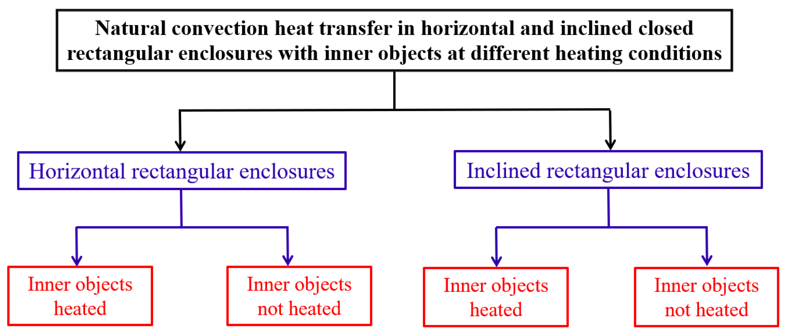
As the studies on the NCHT in enclosures, either with or without IOs at different heating conditions, are plentiful, the scope of the present review is exclusively limited to only the NCHT in horizontal and inclined closed rectangular enclosures with IOs at different heating conditions. The literature included in the present review is categorized and thus reviewed in sequence as shown in Figure 1.

2. Relevant Previous Reviews

Ten existing reviews have been found which are related to the specific topic reviewed in the present review [7,8,9,10,11,12,13,14,15,16]. However, their scopes and focuses are significantly different. Furthermore, the present review includes some studies, particularly the latest ones, which were not included, or reviewed in detail, in these previous reviews. Table 1 presents a brief comparison of these ten reviews and main differences from the present review for further clarity.
Bairi et al. [7] reviewed the previous studies on natural convection in cavities, in terms of the cavity geometries, thermal boundary conditions and initial conditions, heat source distributions, nature of the fluid, radiative properties, etc. Various experimental, numerical, analytical, and inverse methods approaches were also evaluated, and a particular focus was placed on parallelogram-shaped cavities. However, there were very limited previous studies which investigated the NCHT in inclined cavities and with internal objects.
Das et al. [8] conducted a comprehensive review on previous studies related to natural convection within some common non-square (triangular, trapezoidal, parallelogrammic) enclosures as well as enclosures with curved and wavy walls filled with pure fluids, porous media, and nanofluids. As the scope of this review is limited to non-square enclosures, it included very limited previous studies on the specific topic of the present review.
Miroshnichenko et al. [9] reviewed the previous studies on the turbulent natural convection heat transfer in rectangular cavities. These are apparently different from the previous studies included in the present review, which considered only the laminar NCHT in rectangular enclosures, as will be shown below.
Pandey et al. [10] carried out a comprehensive review of previous studies on natural convection in enclosures with and without IOs in various shapes. This review included numerous previous studies which are very related to the specific topic of the present review and thus included here. The major difference is that the present review presents a very detailed and comprehensive review on the previous studies which exclusively investigated the NCHT in horizontal and inclined closed rectangular enclosures with IOs at different heating conditions. Similarly, the review by Rostami et al. [11], which is a very comprehensive review on the effects of the governing parameters of natural convection in differently shaped cavities with and without nanofluids, is very relevant as it also included many previous studies which considered IOs and inclined enclosures, although the reviews on these included studies are not exhaustive and detailed enough compared to the present review. In addition, Abdulkadhim et al. [13,14] presented exhaustive reviews on the previous studies related to the natural convection in complex enclosure forms including trapezoidal, rhombic, elliptical, and wavy geometries. They included many previous studies which considered IOs with different shapes but they were not reviewed in detail. Some of these studies are also included in the present review. Another very related review was conducted by Alsabery et al. [15], which focused on natural and mixed convection of IOs related to cavities filled with regular and nanofluids. Again, many previous studies which considered IOs with different shapes were not reviewed in detail by them. These are also included and reviewed in detail in the present review.
Hussien et al. [12] conducted a comprehensive review of numerical and experimental studies related to heat transfer and entropy generation in cavities along with their applications. The review included numerous previous studies covering a wide range of aspects, including fluid thermal properties, cavity configuration, boundary and initial conditions, external force, thermal source discretion, and geometries. However, it included limited previous studied within the scope of the present review.
A very recent systematic review related to the specific topic of the present review was conducted by Saha et al. [16], which focused on previous studies related to heat transfer analysis in different cavities with or without fins, obstacles, cylinders, and baffles, as well as the use of pure fluids and nanofluids as the medium in cavities. This review included close to 300 previous studies. Due to this, the review of previous studies on the specific topic of the present review is not systematic and detailed.
It is apparent that, although there are some reviews on the existing studies related to the specific topic of the present review, a comprehensive and detailed review exclusively devoted to only the NCHT in horizontal and inclined closed rectangular enclosures with IOs at different heating conditions is lacking and needed. This motivated the present review.

3. Statistics of the Previous Studies Reviewed

Within the scope of this review, i.e., the natural convection heat transfer in horizontal and inclined closed rectangular enclosures with inner objects at different heating conditions, 146 previous studies were identified from the literature and reviewed comprehensively in this review paper. The key statistics of the previous reviewed studies is presented in Figure 2.
From Figure 2, it is seen that the studies with a single IO are the most common (69%), followed by two IOs (19%), and only 18 studies considered more than two IOs, and the number of studies that dealt with different shapes varies substantially, with the circular IOs being the most studied (43%), followed by square objects (26%), elliptic objects (12%), thin plates (9%), rectangular objects (5%), and only seven studies considered objects in other shapes.
In the subsequent sections, these 146 previous studies are reviewed and categorized in the sequence shown in Figure 1.

4. Horizontal Closed Rectangular Enclosures

4.1. Inner Objects Heated

4.1.1. Circular Objects

One Circular Cylinder

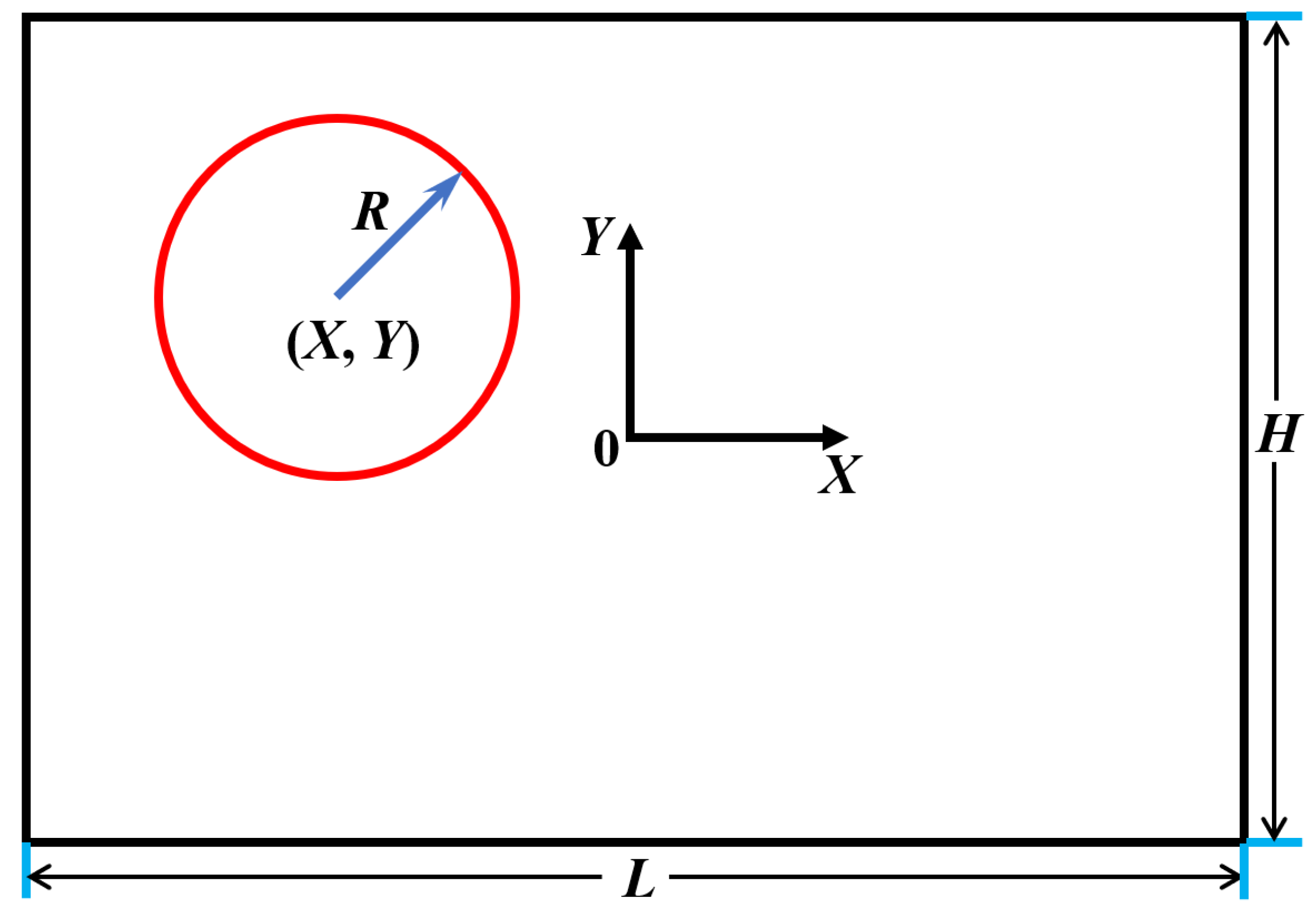
The most studied configuration is a horizontal closed rectangular enclosure with one heated inner circular cylinder (abbreviated as “CC” hereafter) located at (x,y) with a radius r, as sketched in Figure 3.
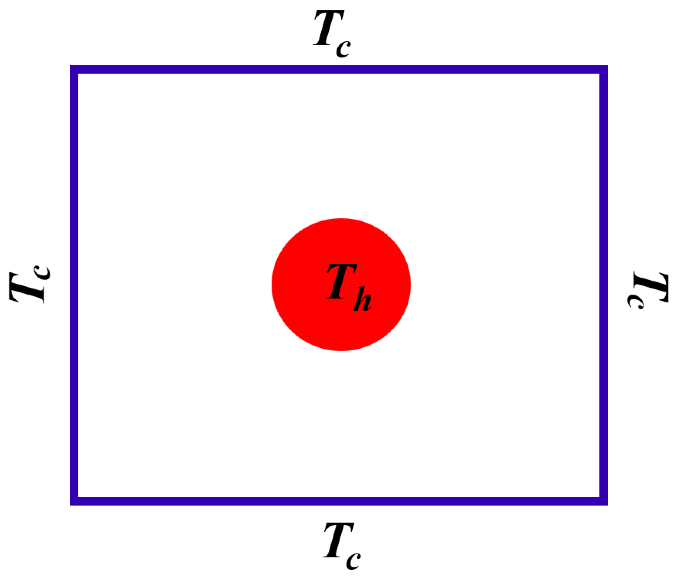
From the literature, it was found that, for the NCHT in a horizontal closed rectangular enclosure with one heated inner CC, the most studied case is that with the boundary conditions on the enclosure and the cylinder as illustrated in Figure 4. The previous studies for such a case are basically numerical, and the key information and the major findings of these studies are summarized in Table 2. It was noted that the majority of these studies assumed that the NCHT was unsteady and only six studies [17,18,19,20,21,22] assumed it was steady. Without exception, all these 23 previous studies assumed that the NCHT was laminar, with R a generally not high (no more than 10 7 ). It was also noted that only four studies [23,24,25,26] assumed that the NCHT was three-dimensional (3D) and the remaining studies assumed it was two-dimensional (2D).
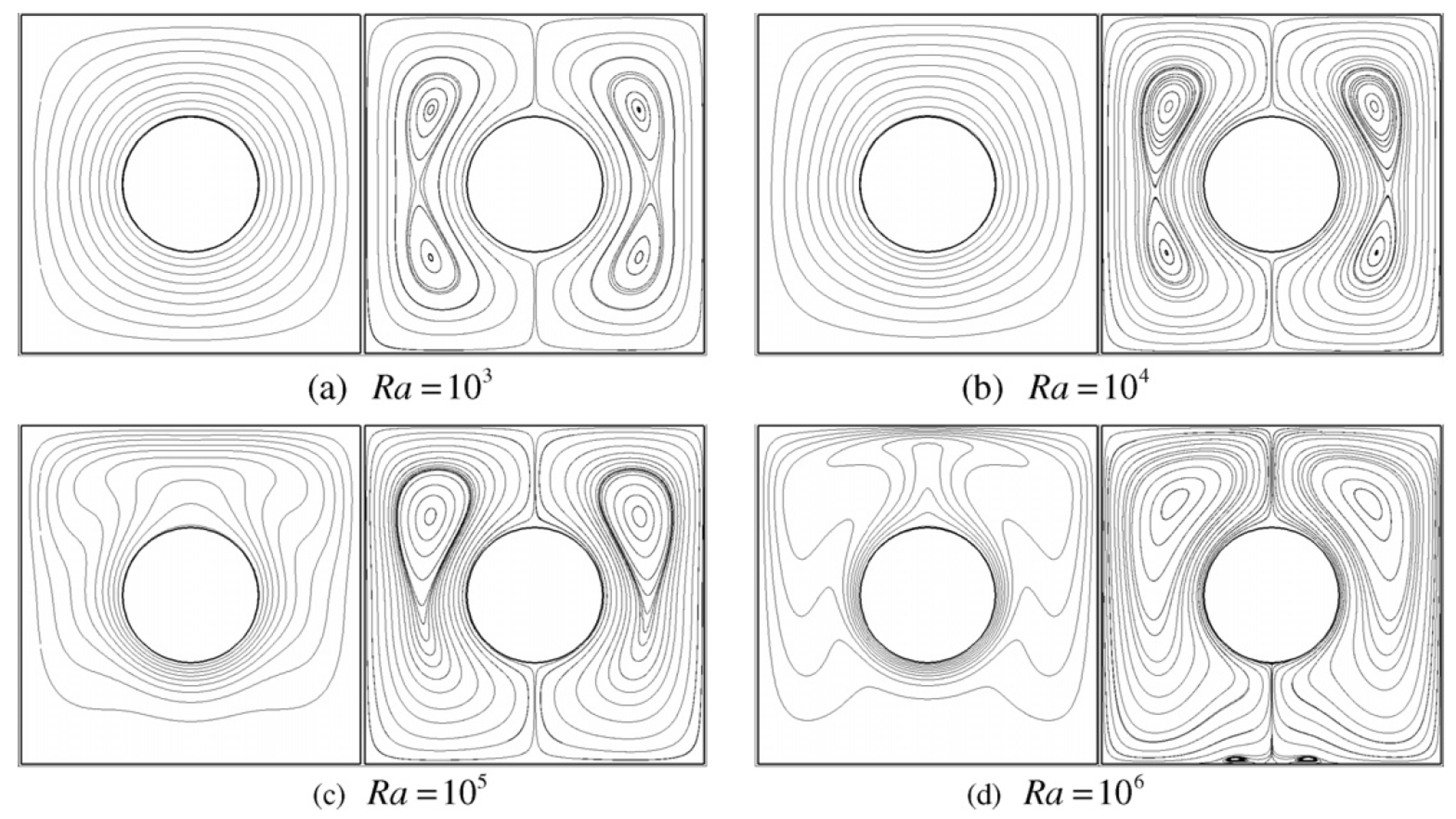
Figure 5 presents the steady state isothermals and streamlines when the inner CC of the size r = 0.2 is at the center of the enclosure for different R a values at P r = 0.7 obtained numerically by Kim et al. [31]. This figure shows that, when R a is no more than 10 6 , the natural convection flow and heat transfer in the enclosure are symmetric about the middle vertical axis. Doo et al. [28] carried out a numerical study to examine the effect of the location of the inner CC of the size r = 0.2 along the middle vertical axis of the enclosure (over 0.2 y 0.2 ) for different R a values in terms of steady state isothermals and streamlines. Kim et al. [31] also obtained the total surface-averaged N u of the enclosure ( N u ¯ s , e n ) and the surface-averaged N u of the inner cylinder ( N u ¯ s , c ) of the size r = 0.2 when it changes the location along the middle vertical axis of the enclosure at P r = 0.7, as shown in Figure 6.
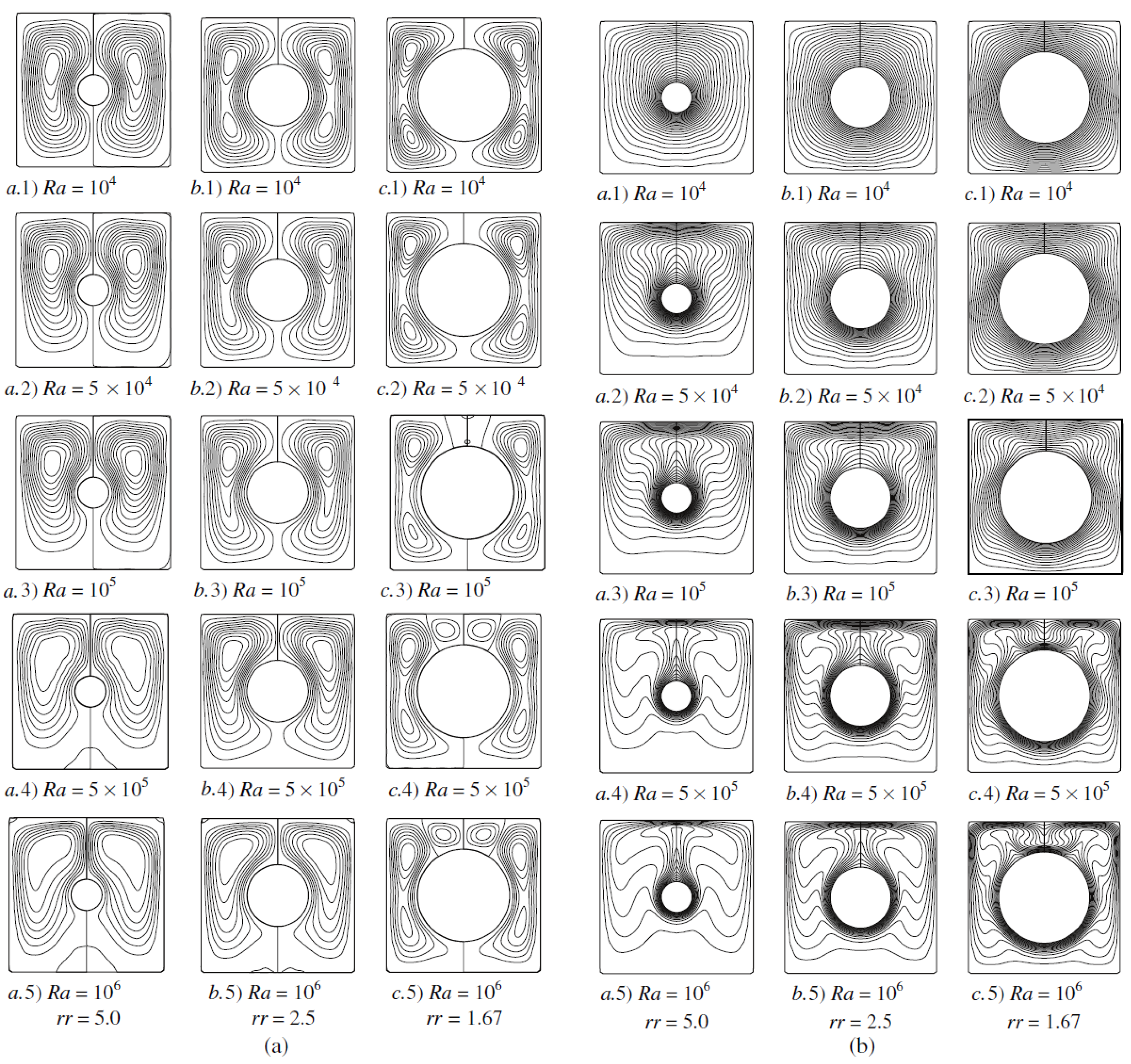
The effect of the inner CC size (r) on the natural convection flow and heat transfer in the enclosure was studied numerically by Shu et al. [18], with the obtained steady state isothermals and streamlines when the centrally located inner CC changes its size ( r = 0.1 , 0.2, 0.3) presented in Figure 7 for different R a at P r = 0.71 .
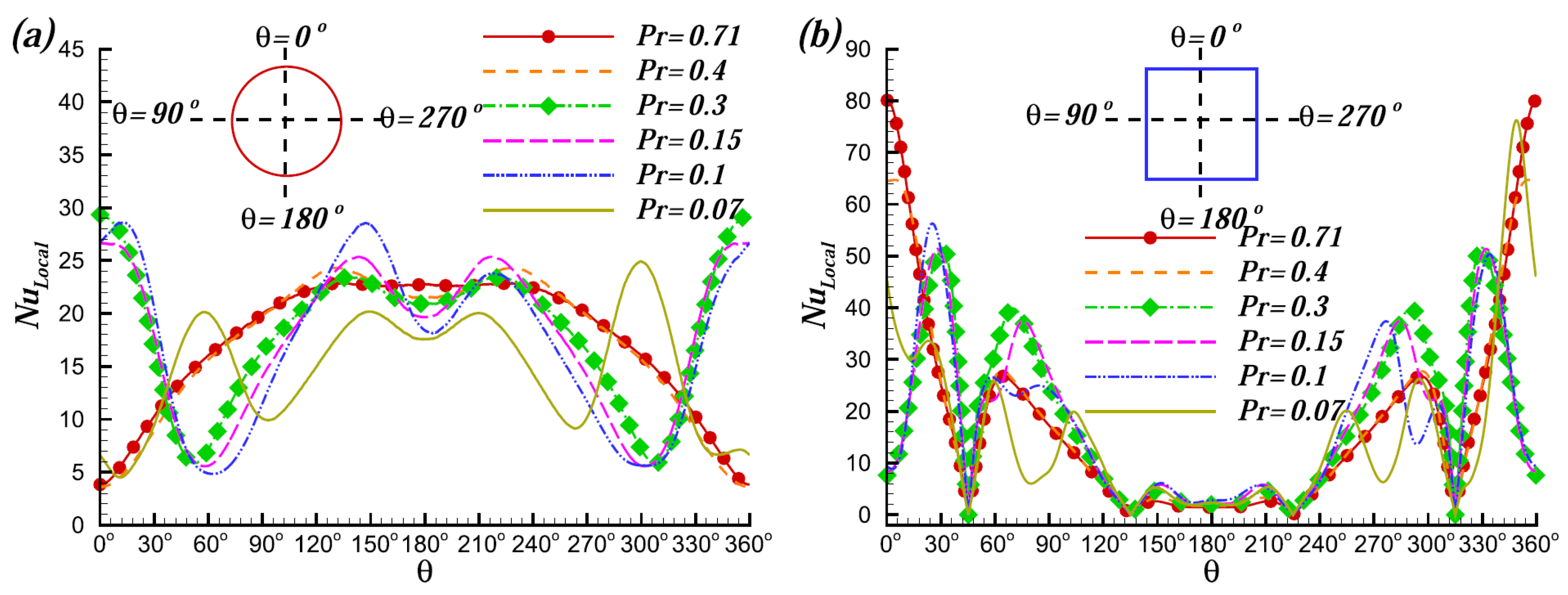
To demonstrate the effect of P r , Liao et al. [32] presented the distribution of the local N u on the inner cylinder surface and enclosure surfaces for different P r ( 0.07 P r 0.7 ) at R a = 10 6 , as shown in Figure 8. They also obtained the flow structure map in the R a P r plane to demonstrate the flow behavior changes, as shown in Figure 9, which shows that, when P r is reduced, the flow experiences transition from steady single thermal-plume state, steady double thermal-plume state, and then to unsteady state for R a 2 × 10 6 , but beyond R a = 2 × 10 6 , the transition is directly from steady single-plume state to unsteady state without going through double-plume regime, with the critical P r of transition from single plume to double plumes decreasing when R a increases. Nevertheless, the critical P r to unsteady regime increases when R a becomes larger. In addition, during the transition from single thermal plume into double thermal plumes, there is an abrupt increase in N u , although the amount is not significant. Liao et al. [33] furthered this study subsequently by developing different scaling laws for N u in the steady and unsteady regions. They found that, in the steady regimes with single thermal plume and triple plume and unsteady regime, the respective averaged N u scale with R a 1 / 4 , R a 1 / 4 P r 0.08 , and ( R a P r ) 1 / 4 , respectively, indicating that, when P r further decreases, its influence on the heat transfer increases.
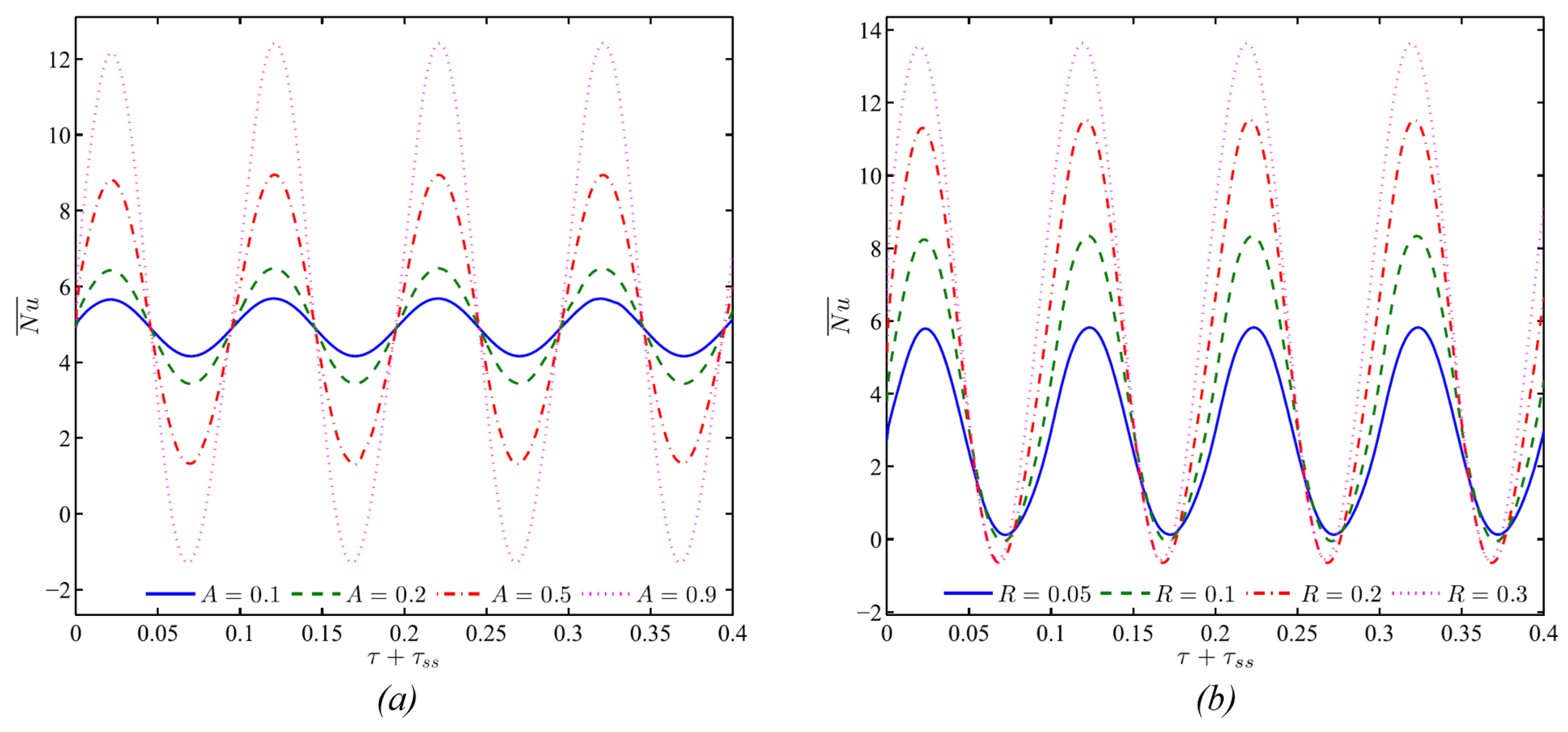
Roslan et al. [34] carried out a numerical study on the 2D unsteady natural convection induced by a temperature difference between a cold outer square enclosure and a hot inner CC. The unique feature of this study is that the cylinder temperature varies sinusoidally with time about a fixed mean temperature. Their results show that the cylinder temperature oscillation can excessively change the flow and temperature fields, and the periodic heat transfer rate follows a sinusoidal law, as shown in Figure 10. They also noted that the heat transfer rate increases by oscillating the source temperature, with the maximum heat transfer augmentation achieved at a frequency from 25 π to 30 π for a high heating amplitude and a moderate source radius. Their results further indicate that the increase in the cylinder radius notably increases the maximum value of the temporal increase but its effect on the minimum value is negligible.
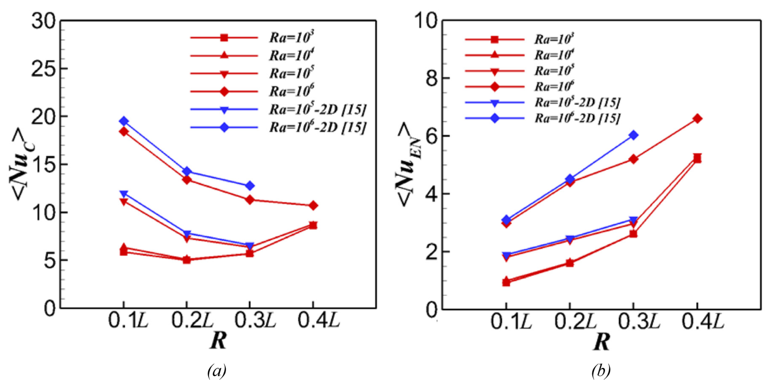
Most of the numerical studies are 2D. When R a is not too high, such 2D assumptions are valid. However, when R a is large enough, the flow and thermal structure will become 3D. Seo et al. [24] conducted 3D numerical simulations to examine the three-dimensionality caused by the transition of the flow regime from steady to unsteady state over 10 3 R a 10 6 over 0.1 r 0.4 by imposing adiabatic boundary conditions on the vertical walls in the longitudinal direction. Their results show that, when R a 10 5 , the flow and thermal structures are almost 2D no matter what r is. When R a increases to 10 6 , almost 2D structures occur at r = 0.1 and 0.2, but as r is increased to 0.3 at R a = 10 6 , the flow transitions from steady state to unsteady state, and when r is increased to 0.4, the structures continue to exhibit unsteady characteristics. The 3D effects are also clearly shown in Figure 11 in terms of the distributions of N u ¯ s , e n and N u ¯ s , c . The authors furthered their study by investigating the natural convection inside a long, cold rectangular enclosure, with a hot CC or an elliptical cylinder, using 3D numerical simulations over 10 4 R a 10 6 and 0.1 r 0.4 [25] by imposing periodic boundary conditions on the vertical walls in the longitudinal direction. For the CC case, the major conclusions obtained by Seo et al. [24] are re-confirmed in this study. The results show that the local N u ¯ s on the top wall reaches a maximum at the center and the minimum occurs on both sides. Nevertheless, the location and peak N u values vary at R a = 10 6 due to the increase in the flow instabilities for different r, indicating that the heat transfer performance is strongly dependent on r. More recently, Seo et al. [26] carried out 3D numerical simulations and artificial neural network modeling with a heated sinusoidal cylinder in a long, cold rectangular enclosure with periodic boundary conditions on the vertical walls in the longitudinal direction too. The results show that, when R a was increased to 10 6 , the flow transitioned from steady to unsteady state with the three-dimensionality; however, for smaller R a , when the mean diameter of the sinusoidal cylinder is the same as the CC, N u is essentially the same, as shown in Figure 12.
Choi et al. [23] also carried out a 3D numerical simulation study on the NCHT in a cubical enclosure with an inner CC, focusing on the effect of the cylinder location when it is moved vertically along the centerline of the cubical enclosure. Their results show that, for all R a values considered, the thermal and flow fields eventually reach steady state. Their results showed that the thermal and flow fields eventually attained steady state for all simulated R a . When R a is small, the 3D effect is non-existent regardless of the position of the internal cylinder, but when R a increases, the 3D effect emerges and grows; particularly, this effect on the heat transfer between the cylinder and the enclosure is great when the cylinder is in the lower half of the enclosure. Their results also show that, when R a increases, the effect of r on the distribution of N u on the surface of the cylinder and enclosure walls increases, and for R a = 10 5 and 10 6 , the maximum N u ¯ s , e n and N u ¯ s , c occur when r = 0.25 , due to the wide space between the cylinder and the top wall of the enclosure which ensures the strong circulation of flow. Nevertheless, r for the minimum N u ¯ s , e n and N u ¯ s , c depend on R a because the strength of the local 3D flow increases as R a increases. They further show that, as R a increases, the differences in the values of N u ¯ s , e n and N u ¯ s , c increase between the 3D and 2D simulation results.
For the majority of the previous studies on the problem with the BC type shown in Figure 4, the media in the enclosure are pure fluid or nanofluid. Wang et al. [36] studied numerically with LBM the case with the media in the enclosure being porous, which has an exponentially temperature-dependent viscosity. Their numerical study investigated the influences of R a , Darcy number ( D a ), viscosity variation index (n), inter-phase heat transfer coefficient (H), modified conductivity ratio ( λ ), and porosity of the porous media ( ϵ ) on the fluid flow and heat transfer. Their results show that, for a given R a , there is a critical Darcy number ( D a c ). When D a < D a c , increasing D a has minimal effect on the fluid and solid phase N u . However, when D a > D a c , increasing D a also increases N u , especially at high R a . The average fluid and solid phase N u increases when n is reduced. An increase in ϵ usually enhances N u of the solid phase, which is more distinct when D a > 10 4 , while N u of the fluid phase generally decreases when ϵ is increased. Also, their results showed that increasing λ and H usually leads to a remarkable increase in N u of the solid phase but causes little change in N u of the fluid phase.
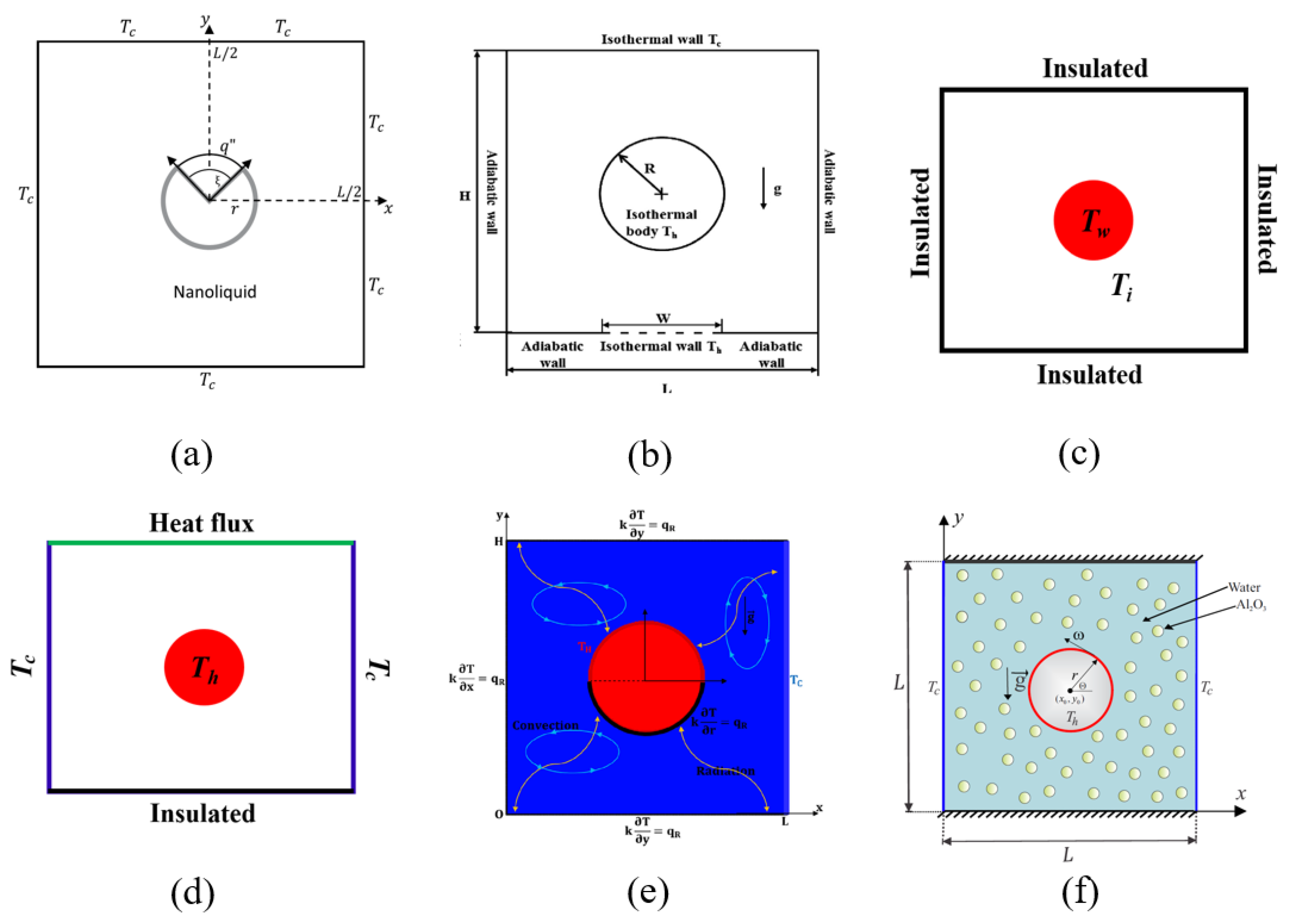
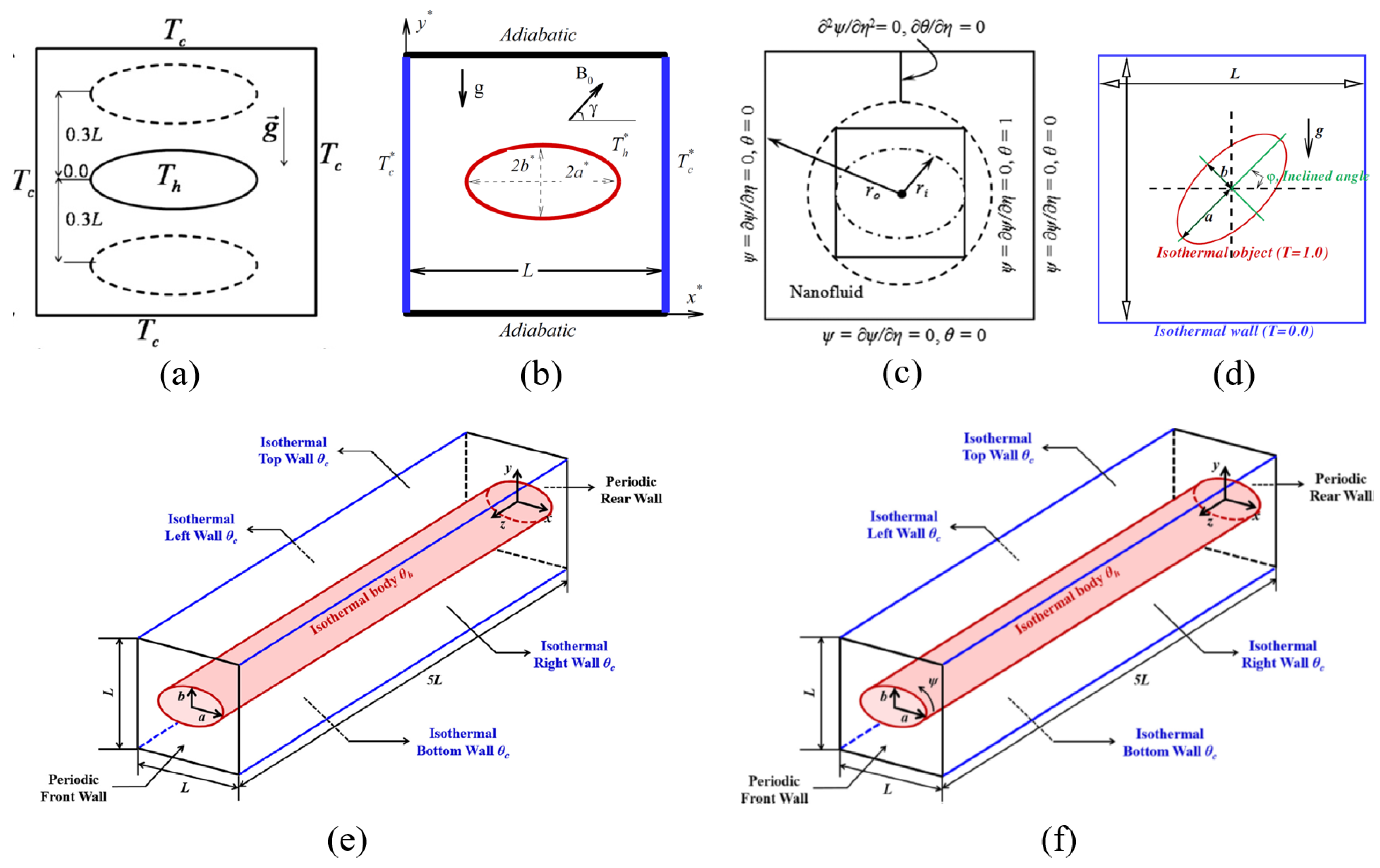
In addition to the most studied case with the type of the boundary conditions applied on the enclosure and the inner CC, as illustrated in Figure 4, there are some previous studies which investigated the cases with other types of boundary conditions applied on the enclosure and the inner CC. Several types of such boundary conditions used in some previous 2D numerical studies are illustrated in Figure 13.
Alhashash [40] numerically studied the natural convection of nanoliquid in a square porous enclosure containing an internal CC of which the surface is partially heated, as illustrated in Figure 13a. Their numerical simulation results show that the streamlines, isotherms, and nanoparticles isoconcentrations are symmetrical about the length of the enclosure, and a higher nanoparticles distribution occurred at the heated surface segment for a given mean concentration. The results also show that, in general, the ratio of N u per unit area of the heat source decreases as the portion of the heated surface segment increases, which is intensified when the top half of the cylinder is heated and for high values of the Darcy number at higher nanoparticles concentration.
Lee et al. [41] carried out 2D numerical simulations for the unsteady NCHT in an enclosure with a hot inner cylinder of the size of r = 0.2 located at the center of a cold enclosure over 10 3 R a 10 6 with P r = 0.7 , by examining the effects of the locally heated bottom wall of the enclosure, as illustrated in Figure 13b. Their numerical simulations were performed by using the IBM. They found that the changes in the size of the local heating zone have minimal influence on the flow and thermal structures when R a 10 4 , resulting in little changes in the overall N u between the top wall and the cylinder surface. When the size of the local heating zone is increased, the size of the small inner vortices formed in the lower portion of the cylinder changes substantially at R a = 10 5 . When R a = 10 6 , flow separation from the side wall causes secondary vortices to be generated in the lower portion of the cylinder. The size of the local heating zone influences the generation and dissolution of vortices.
Sasaguchi et al. [42] carried out 2D numerical simulation of the unsteady natural convection in water around a cooled horizontal cylinder placed at the center of a rectangular enclosure with r = 0.25 by using the FDM, with the boundary conditions applied to the enclosure and the inner CC, as illustrated in Figure 13c, to examine the effects of the density inversion and the initial temperature of water on the cooling process. It was found that a change in the initial water temperature largely affects fluid flows and local N u due to the density inversion of water. The authors carried out a further 2D numerical study [43] using the same boundary conditions as illustrated in Figure 13c to investigate the effect of the location of the inner cylinder (at y = 0.25 , 0, and 0.25, all at x = 0 ). Their results show that the location of the cylinder significantly changed the transient flow behavior, leading to complicated heat transfer mechanisms.
Cesini et al. [44] carried out a numerical and experimental study of the 2D steady state NCHT with the boundary conditions applied to the rectangular enclosure and the inner CC, as illustrated in Figure 13d using the FEM. In this study, there was heat transfer with the overall heat transfer coefficient of 10 W/( m 2 · K) on the top wall. Their corresponding experimental measurements were obtained by a holographic interferometer. They found that both the enclosure aspect ratio and R a have significant effects on the temperature distribution and thus on N u , with increasing R a and decreasing enclosure aspect ratio resulting in larger N u .
Boukendil et al. [45] conducted a 2D numerical study of the unsteady natural convection coupled to surface radiation in an asymmetrically cooled square cavity with complicated boundary conditions applied on the enclosure and the inner CC ( r = 0.2 ), which is partially heated and located at the center of the enclosure, as illustrated in Figure 13e, by using the FVM the discrete ordinate methods. The perimeter of the cylinder is divided into two equal parts, with the upper half isothermal at a higher temperature while the lower one thermally insulated. The study investigates the hydrodynamic and the thermal behavior of the fluid, the convective and the radiative heat transfer over 10 3 R a 10 7 , and the common emissivity 0 ϵ 1 of the inner and outer surfaces with P r = 0.71 . Their results show that both R a and the surface radiation have a significant influence on the flow structure and heat transfer characteristics in the enclosure. It was found that, by increasing R a in the absence of the surface radiation, the convection is strengthened above the heating element while conduction persists below the passive portion of the cylinder. The intensity of the flow becomes much higher, especially in the lower part of the enclosure, where the shape of the thermal plume above the cylinder is affected due to an effective cooling of the fluid near the upper passive wall, and when surface radiation is taken into account, about one half of the global heat transfer comes from the radiative heat transfer.
Alsabery et al. [46] carried out a numerical study with Al2O3/water nanofluid due to a rotating heated inner CC located at the center with two vertical walls at cold temperature and the top and bottom wall insulated, as illustrated in Figure 13e over 10 4 R a 10 7 , 0 ω 600 ( ω is the angular rotational velocity), 0 ϕ 0.04 ( ϕ is the nanoparticles concentration), and 0.1 r 0.4 with P r = 4.623 . As an example, the evolution of the streamlines, isotherms, nanoparticle distribution, and isentropic lines for different r values are presented in Figure 14 to demonstrate the effect of r. Their results show that, when the rotational velocity of the cylinder is increased, the strength of the streamlines and distribution of the fluid heat flow increases. Increasing R a and ϕ increases the convective heat transfer and the average N u . Increasing the ϕ and ω for upper values of radius of the rotating cylinder causes the global entropy generation to increase due to the heat transfer irreversibility. For a stationary cylinder, heat transfer irreversibility is dominant. For a rotating cylinder, the generated entropy is from the nanofluid friction irreversibility. It was also reported that a smaller size cylinder and a moderate rotational velocity produce an enhanced N u . Mehryan et al. [47] examined the effects of Cu-Al2O3/water hybrid nanofluid and Al2O3/water nanofluid with a hot oscillating CC of the size r = 0.1 . The enclosure walls were adiabatic and the cylinder oscillated sinusoidally along the vertical middle line of the enclosure. The numerical simulations were carried out over 10 3 R a 10 6 , 0.0 ϕ 0.02 , 0.25 y o 0.25 ( y o is the oscillation amplitude of the cylinder), and 0.5 f 48 (f is the frequency), with P r = 6.2 . The results show that both the motion of the oscillating cylinder toward the top and bottom walls and the presence of the nanoparticles increase the average N u for small R a , and for N u a simple Al2O3/water nanofluid is larger than that of a Cu-Al2O3/water hybrid nanofluid.
In addition to the above studies, Shyam et al. [48] also carried out a numerical study on the 2D steady laminar NCHT in a horizontal square enclosure filled with an incompressible power-law fluid caused by a horizontal centrally located inner CC which is at a higher temperature or dissipating heat at a constant rate. The top and bottom walls of the enclosure are adiabatic but the two vertical walls are at a lower temperature. The numerical simulation results were obtained over 10 2 R a 10 6 , 0.71 P r 100 ; 0.2 n 1.8 and 0.25 y 0.75 , where n is the power-law index. Three positions of the cylinder (at the center, close to the upper wall and close to the bottom wall) along the vertical center line were considered to examine the effect of the symmetric and asymmetric confinement. The results show that the local and surface average N u for the cylinder positively depends on R a , but reduces when the cylinder is moved in the direction of the top wall due to the lack of participation of the cold fluid under the cylinder. However, all else being equal, N u is enhanced with shear-thinning fluid behavior and is impeded with shear-thickening, particularly when R a is high.
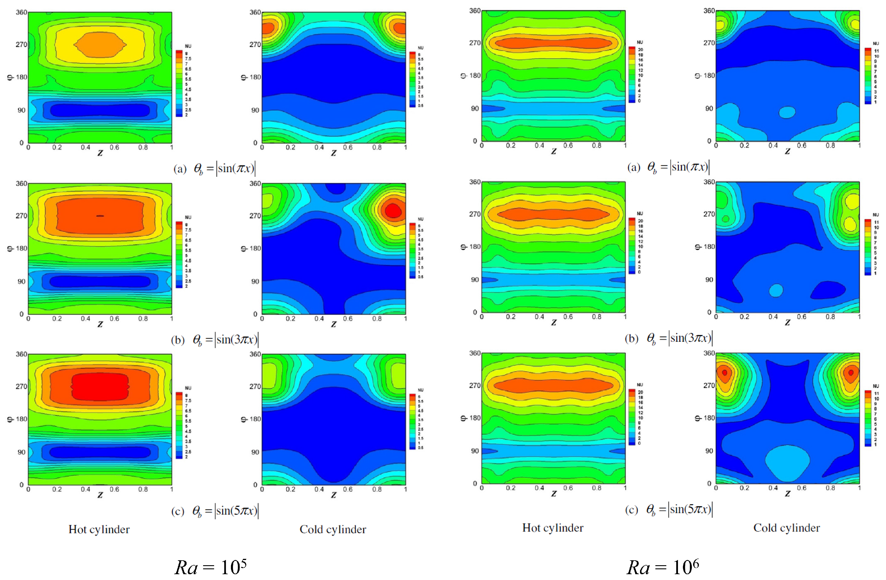
There are two studies with 3D numerical simulations of the NCHT in a closed horizontal rectangular enclosure with an inner CC with different boundary conditions applied on the enclosure and cylinder [49,50]. Choi et al. [49] carried our 3D numerical simulations of the unsteady laminar NCHT in a rectangular channel with an inner cold CC using IBM. The two vertical side walls were adiabatic, the top wall and the cylinder were cold (at T c ) and the bottom wall was hot, and the longitudinal direction had periodic boundary conditions. The rectangular channel had the cylinder at the center but its size varied over 0.1 r 0.4 . P r = 0.7 and 10 3 R a 10 6 are considered in the simulations. They found that, for the considered r and R a , the thermal and flow field can be categorized into six regimes: steady symmetric 2D convection, steady asymmetric 2D convection, steady symmetric 3D convection, steady asymmetric 3D convection, time periodic convection, and aperiodic convection, and the map of thermal and flow regimes was presented in terms of r and R a . The results show that, generally, the thermal and flow fields have higher stability when a cold CC is inserted into the channel in comparison to a rectangular channel without an internal CC. The thermal convection generated by the cylinder causes the affects of the thermal convection on the thermal and flow fields to be concentrated on the lower portion of the rectangular channel when r increases. Furthermore, the presence of a cold cylinder makes both the thermal and viscous boundary layer thinner as r and R a increase. The presence of a cold cylinder also resulted in an enhanced N u , although the enhancements are strongly dependent on R a and r, in different styles. The comparison of N u from 2D and 3D calculations shows that the 2D results are very different from 3D results over 10 5 R a 10 6 , indicating that 2D calculations are unsuitable to examine thermal and flow fields in the configuration considered in this study. Lee et al. [50] carried out 3D numerical simulations for the unsteady laminar NCHT with a CC located inside a cold cubic enclosure having R a values ( 10 5 R a 10 6 ) at P r = 0.7 using the IBM/FVM. In this study, the vertical side walls and the top wall were at a lower temperature T c and the cylinder was either at a high temperature T h or T c . The two vertical walls in the longitudinal direction were adiabatic. The bottom wall was at the temperature of a sinusoidal profile ( θ b = s i n ( n π x ) ). The CC of the size r = 0.2 was located at the center of the cubic enclosure. Detailed 3D flow and thermal structures were analyzed in terms of streamlines, 2D, and 3D isotherms. It was observed that the flow and heat transfer characteristics vary significantly due to the variation in the thermal boundary conditions on the bottom wall and the cylinder surface in the convection-dominant region. The distribution of the local N u also varies significantly when the thermal boundary conditions on the bottom wall and the cylinder surface change for different R a values, as shown in Figure 15 as an example.
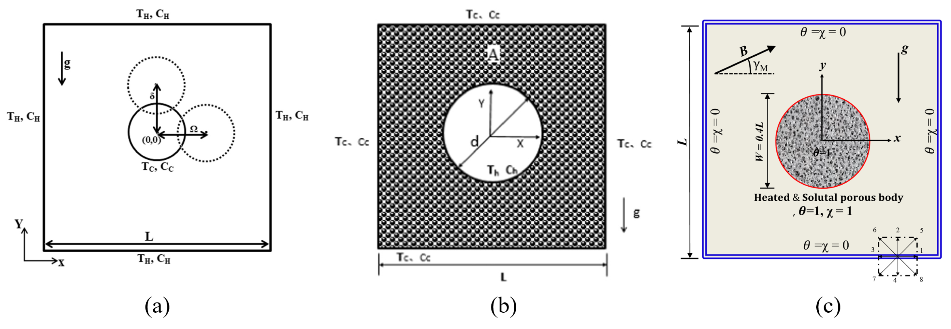
Double-diffusive NCHT in a horizontal closed rectangular enclosure with an inner CC with different types of boundary conditions has already drawn attention. Kefayati et al. [51,52] carried out numerical studies on the 2D laminar unsteady double-diffusive NCHT and entropy generation with non-Newtonian Carreau fluid with the boundary conditions as illustrated in Figure 16a. They examined the effects of R a ( 10 4 and 10 5 ), Carreau number C u (1, 10, and 20), Lewis number L e (2.5, 5 and 10), Dufour parameter D f (0, 1, and 5), Soret parameter S r (0, 1, and 5), Eckert number E c (0, 1, and 10), buoyancy ratio N (−1, 0.1, and 1), r (0.1, 0.2, 0.3, and 0.4), x (−0.2, 0 and 0.2), y (−0.2, 0, and 0.2). Their results show that a higher R a increases N u , while the increase in power-law index makes heat and mass transfer to reduce gradually. The increase in L e reduces the mass transfer significantly but causes heat transfer to only drop marginally. N u increases with D f and the mass transfer is improved as S r increases. The increase in N enhances both heat and mass transfer. The increase in C u results in gradual reduction in heat and mass transfer. The change in y from the bottom to the top decreases heat and mass transfer significantly while the change in x enhances heat and mass transfer although the increment is different in various power-law indices. The increase in r enhances heat and mass transfer. On the other hand, Xu et al. [53] carried out numerical studies with the case as illustrated in Figure 16b. The effects of Darcy number ( 10 4 D a 10 2 ), Lewis number ( 0.2 L e 10.0 ), and buoyancy ratio ( 50.0 N 10.0 ) at R a = 10 5 and P r = 1 on the double-diffusive NCHT were examined. The results show that D a has a significant effect, with the increasing D a resulting in significant thermal and solutal plumes above the heated cylinder and enhanced heat and mass transfer; the double diffusive natural convection is dominated by large N no matter whether it is negative or positive; the averaged N u decreases gradually when D a is increased; and at N = 50 and L e = 2.0 , the flow undergoes steady state, unsteady doubling periodic oscillation, quasi-periodic oscillation, and non-periodic oscillation when D a varies. Vijaybabu [54] carried out a numerical study with the case as illustrated in Figure 16c over 5 N 5 , 10 5 D a 10 3 , Hartmann number 0 H a 50 , and magnetic field angle 0 γ m 90 It was found that the increases in D a , N, and γ m enhance the heat and concentration transfers and the increase in permeability significantly enhances the flow-field intensity around the cylinder; the combination of D a and γ m induces unsteady characteristics in the enclosure, and the increase in γ m expands the range of N for the production of unsteady traits; the irreversibilities due to concentration transfer are higher than that of other associated irreversibilities in the enclosure; the increase in positive N values tends to suppress the fluid-friction and magnetic irreversibilities; and the magnetic field direction can significantly impede the effect of magnetic field on the double-diffusive natural convection as well as entropy generation.
Although the previous studies on NCHT in a horizontal closed rectangular enclosure with an inner CC at a different temperature (and concentration for several studies) are mostly numerical, as noted and shown above, two previous experimental studies have been found. Ekundayo et al. [55] conducted an experimental study on the NCHT in long square-sectioned relatively cold insulated enclosure with a heated inner horizontal CC, which is of a very small size and was traversed horizontally and vertically. The medium in the enclosure was air and the cylinder was heated with heat fluxes which result in R a = 7 × 10 4 and 10 5 . The results show that convection reduced when the horizontal wall was present regardless of the position of the heated cylinder, whereas the presence of vertical walls may enhance convection if the cylinder is located approximately half-way up the enclosure. Furthermore, for the central vertical traverse, the optimal position to achieve the maximum N u shifts vertically upwards (over 0.25 y 0.5 ) as R a increases; with the cylinder traversed horizontally and located far from any horizontal wall, the minimum N u occurred at x = 0.25 and 0.75, although when located near the base or along the crown, this occurred at x = 0.5 ; a localized chimney effect was generated in the enclosure when the cylinder was very close to a vertical wall, which enhances N u . Another experimental study was carried out by Butler et al. [56], who investigated the natural convection flow and heat transfer due to a horizontal inner CC at a higher temperature enclosed in a cold square enclosure with its surfaces approximately adiabatic using surface temperature measurements and the 2D Particle Image Velocimetry (PIV) technique over 2 × 10 4 < R a < × 10 4 with air ( P r = 0.71 ) as the medium. The centrally located cylinder was of the size r 0.1 . The study focused on the effect of the natural convective plume from the cylinder on the heat transfer and internal fluid flow structures. Their results show that, at the lower values of R a considered, the cylinder N u follows the correlations from the literature, but as R a increases, they deviate from these correlations, as N u is increased due to the interaction of the cylinder and cavity. Their PIV results show that a transition process occurs, whereby the flow transitions from being influenced by the temperature variation across the enclosure to the temperature variation as a result of the cylinder.
From the literature, it was noted that there have been some previous studies which studied the natural convection flow and heat transfer in a horizontal rectangular enclosure with a heated inner CC with a different configuration [57,58,59,60,61,62,63,64,65,66,67]. The major differences in these cases are that the enclosure surfaces were generally insulated and the natural convection was produced by the temperature difference between that on the cylinder surface and the surrounding medium (air or water in experimental studies) in the enclosure, and more significantly, the top boundary was not closed, but open to the ambient (usually air for the experimental studies). Such studies particularly investigated the natural convection boundary layers and buoyant plume produced and the transition of flow from laminar to turbulent regime, generally at high and very high R a values (as high as 3.6 × 10 13 [62]). Some advanced experimental techniques such as PIV/LIF (laser-induced fluorescence) and numerical simulation techniques such as LES (Large-eddy simulation) have been employed by these studies. Nevertheless, as the cases considered in these studies are different from the case considered in the review, the details of such studies are not presented.

Two Circular Cylinders

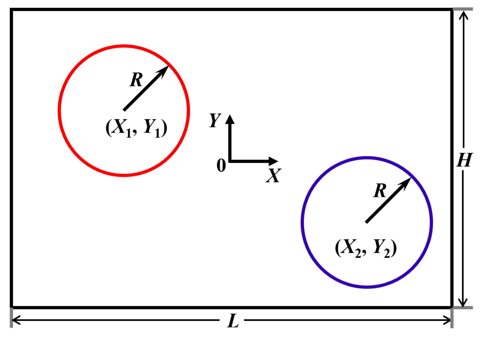
The most studied configuration is the one in a horizontal closed rectangular enclosure with two inner circular cylinders which are located at ( x 1 , y 1 ) and ( x 2 , y 2 ) with the same radius r and at different temperatures, as sketched in Figure 17.
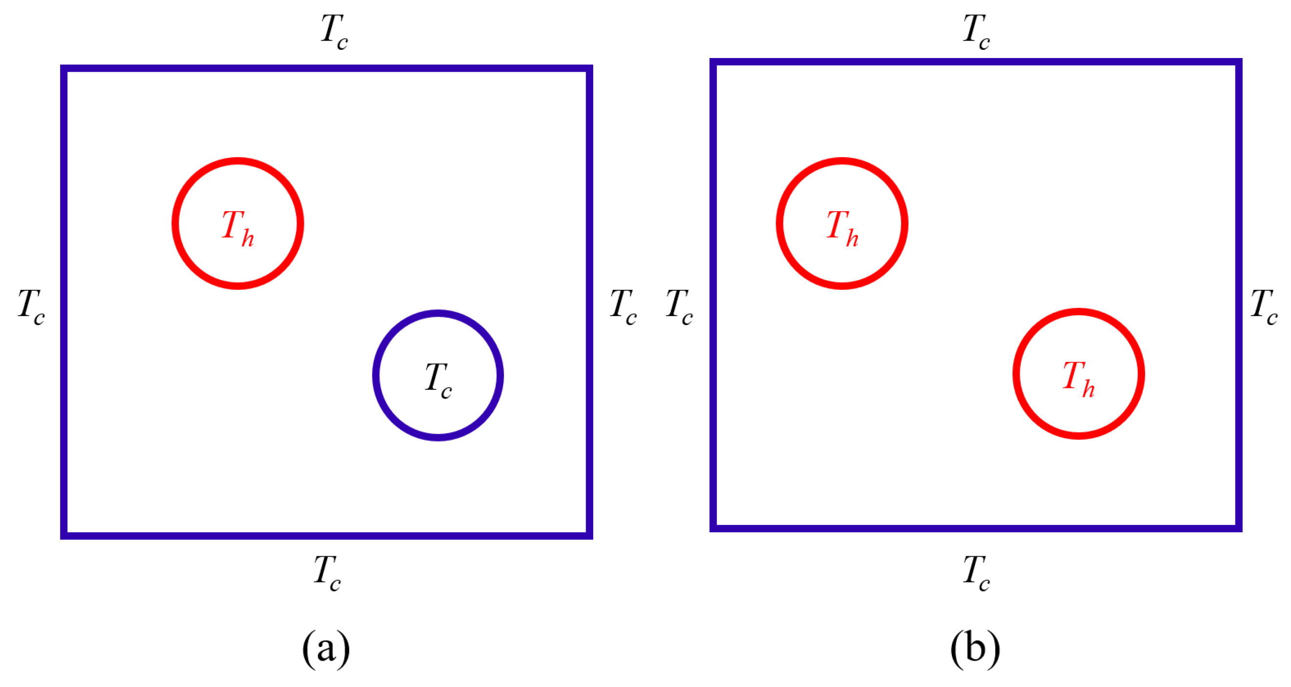
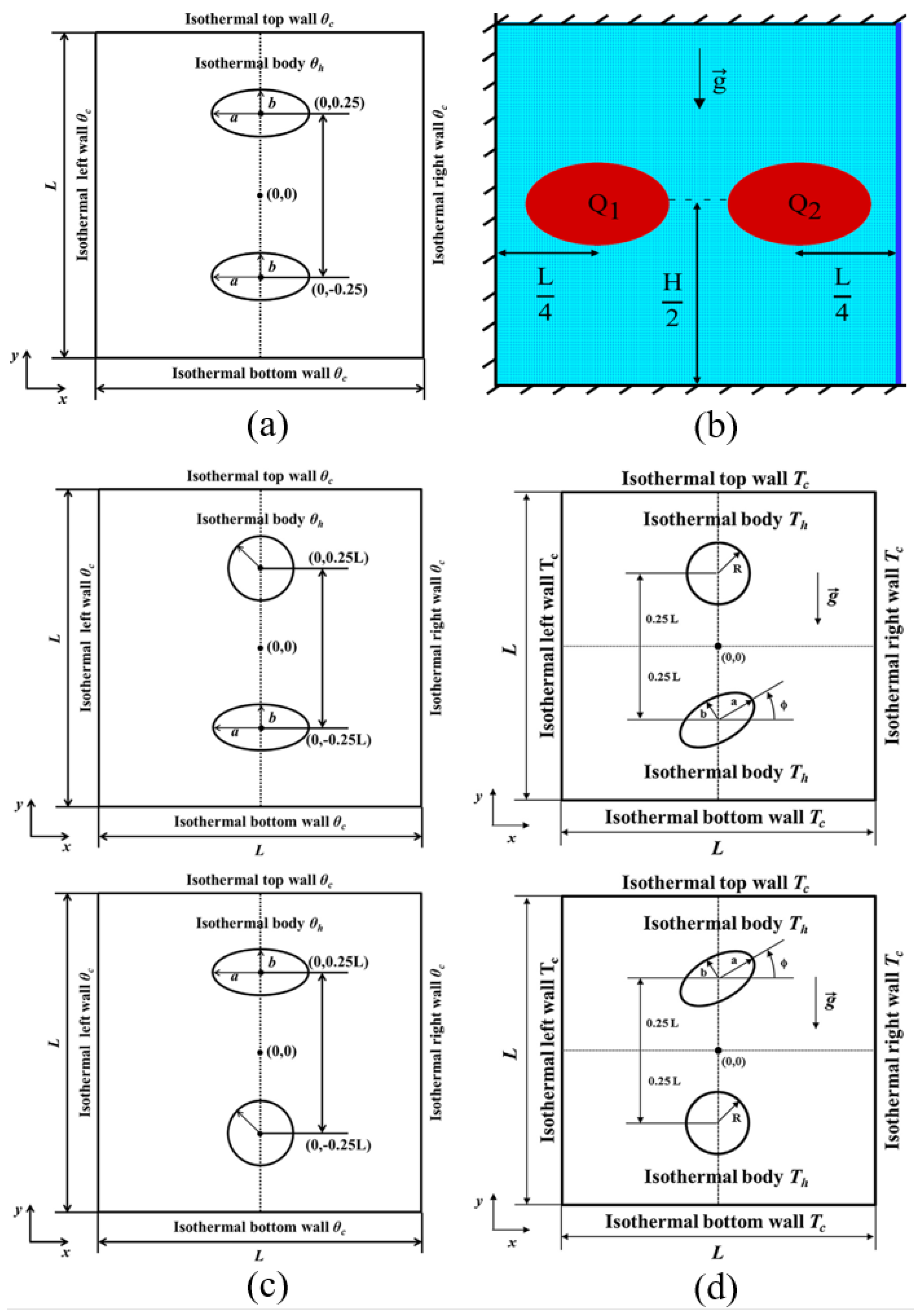
From the literature, it was found that, for the NCHT in a horizontal closed rectangular enclosure with two inner CCs at different temperatures, the most studied cases are the ones with the boundary conditions on the square cavity and the cylinders, as illustrated in Figure 18. Six and three previous studies have been found which deal with Case (a) and Case (b), respectively, as illustrated in Figure 18a,b. All these nine studies are numerical, with the their key information and the major findings summarized in Table 3. It was noted that all these studies assumed the NCHT was 2D, with four studies [68,69,70,71] assuming it was steady and the remaining five studies [72,73,74,75,76] assuming it was unsteady. Without exception, all these nine previous studies assumed the NCHT was laminar, with R a generally not high (no more than 10 7 ). The numerical method used by Baranwal et al. [69,70,71] and Mishra et al. [68] is the FEM-based COMSOL Multiphysics, while that by Park et al. [72,74,75] and Yoon et al. [73,76] is the IBM/FVM. A summary of the most studied cases in the previous studies is presented in Table 3.
As an example for the NCHT in Case (a), Park et al. [72] used the steady-state isotherms and streamlines in the square enclosure when the two cylinders of the size r = 0.2 are at three different heights ( y 1 = y 2 = 0.25 , 0 and −0.25, all with x 1 = 0.25 and x 2 = 0.25 ) at R a = 10 4 , 10 5 , and 10 6 , respectively, and the distributions of the local N u on the surfaces of the cylinders and the enclosure when the two cylinders at these three heights, to show that the position of the cylinders significantly affects the distributions of the flow and thermal fields which also strongly depend on the buoyancy-induced convection by the rising thermal plume from the hot cylinder. When R a was low ( 10 4 ), conduction and position of the cylinder predominantly influenced the fluid flow and heat transfer. The local N u peaks on the surfaces of the cylinders and the enclosure occurred where the distance between the cylinder surfaces and the enclosure wall was the shortest, when the two cylinders were positioned closer to the top wall of the enclosure. Also, as a function of y, N u profiles on the enclosure exhibited almost symmetric shapes with reference to y = 0 . Nevertheless, for higher R a , the fluid flow and heat transfer in the enclosure were influenced by the increased effect of the buoyancy-induced convection as well as the position of the cylinder. Different distribution of local N u at the cylinders and enclosure arose, in comparison to lower R a , as the rising plume from the hot cylinder slanted toward the upper right portion of the enclosure and interacted with the cold cylinder and enclosure, based on the position of the cylinders and R a . The results also show that, as both the magnitudes of y 1 , y 2 and R a increased, N u at the top wall generally increased due to the increase in convection and the reduction in distance between the cylinders and the enclosure top wall. Conversely, N u of the bottom wall decreased due to the increased stagnation region at the lower portion of the enclosure as well as the increased distance between the cylinders and enclosure top wall. The profiles of N u on the enclosure as a function of y are not symmetric due to the increasing effect of convection with the increasing R a .
Baranwal et al. [69] extended the study of Park et al. [72] to examine the effect of P r , while Baranwal et al. [70,71] further extended these studies to the scenarios where the fluids in the square enclosure are non-Newtonian power-law and Bingham plastic fluids. Mishra et al. [68] carried out a similar numerical study with power-law fluids like Baranwal et al. [70] did. However, the difference between these two studies is that, in the latter, the two cylinders change their locations in the vertical direction only, while in the former, they change their locations in the horizontal direction as well as in the diagonal direction.
Yoon et al. [73] also considered Case (a) in their study, but focusing on the effect of the size of the two inner CCs (over 0.05 r 0.2 ) when they are at ( x 1 = 0 , y 1 = 0.25 ) and ( x 2 = 0 , y 2 = 0.25 ) for 10 3 R a 10 6 at P r = 0.7 . Their results show that, for all R a considered, as r increases, a wider dead zone of heat transfer and fluid flow forms as the cold upper cylinder occupies more area in the top half of the cold enclosure. No matter what r is, the flow circulation exhibits two overall rotating symmetric eddies and the secondary vortices over the top surface of the upper cylinder. r substantially influences the trajectories of the primary eddy and secondary vortices, particularly at high R a . They also found that the surface-averaged N u ¯ s at the top enclosure wall is much lower in comparison to the bottom enclosure wall and the enclosure side walls. It was further noted that N u ¯ s at the top wall decreases when r increases due to a wider dead zone, whereas conversely, N u ¯ s on the bottom and side walls exhibit an increasing pattern when r is increased as denser isotherms are formed by conduction due to the reduced space.
Different from Case (a) shown in Figure 18a, the two inner CCs in Case (b) are at the same higher temperature T h . It is expected that the NCHT in Case (b) will be significantly different from that in Case (a).
As an example for the NCHT in Case (b), Park et al. [74] used the steady state isotherms and streamlines in the square cold enclosure when the two horizontally oriented cylinders of the size r = 0.2 are at different heights ( y 1 = y 2 = 0.2 , 0, and 0.25, all with x 1 = 0.25 , x 2 = 0.25 ) at R a = 10 4 , 10 5 , and 10 6 respectively, and the corresponding distributions of the local N u on the surfaces of the left cylinder and the enclosure wall, to show that, depending on R a and y 1 = y 2 , the natural convection bifurcated from steady to unsteady state. More specifically, the flow and thermal fields became unsteady when y 1 = y 2 was between 0 and 0.1 at R a = 10 6 , due to the upwelling plume from the two cylinders and the downwelling plume from the enclosure top wall which moved back and forth in the right and left directions during a particular period of time as a function of time, while for other values considered, they were steady. It was also revealed that, when R a was low (≤ 10 4 ), the profile of the local N u e n on the enclosure walls along the vertical direction of the cylinder demonstrated an almost symmetric distribution along the center of the enclosure, but, when R a 10 5 , the symmetry of N u e n was broken due to the increasing effect of convection with increasing R a . Park et al. [75] carried out a similar study to examine the effects of R a and the locations of the two inner heated CCs. But in this study, the two cylinders were vertically oriented along the vertical centerline of the square enclosure (i.e., x 1 = x 2 = 0 ) and change their vertical positions over 0.15 y 1 0.35 and 0.35 y 2 0.1 , respectively. Their results show that, similarly, the natural convection can be steady or unsteady, depending on R a and y 1 and y 2 . They also obtained the distributions of the local and N u ¯ s , which are also strongly dependent on R a and y 1 and y 2 and compared the results for the two-cylinder case with that for the single cylinder case, which show that N u are larger for the former as more heat is transferred to the enclosure walls, but, the difference in N u on the cylinder in the single cylinder case and in the two-cylinder case depends on R a and y 1 and y 2 as well. Yoon et al. [76] examined the effects of R a and r ( 0.05 r 0.2 ) when the two heated cylinders are vertically oriented ( x 1 = x 2 = 0 ) and at the fixed heights ( y 1 = 0.25 , y 2 = 0.25 ). The results show that, for all R a considered, increasing r causes the space above the upper cylinder and the space below the lower cylinder to be reduced, which in turn leads to a denser distribution of isotherms in those areas. Otherwise, isotherms become coarser in the space between the two hot inner cylinders as the space reduces (when r is increased), and the space becomes occupied with more heated fluids. As r decreases, the convection is considerably influenced by R a . It was also found that, when R a is increased the surface-averaged N u s also generally increased at the top and side walls of the enclosure, but at the bottom wall, it decreased generally when R a increased. N u s on the inner cylinders, for the R a values considered, approximately exhibited the same decreasing and then increasing the pattern when r increased.
In addition to the numerical studies on the 2D laminar NCHT in a square enclosure with two inner CCs at different temperatures, there are several other studies which either carried out 3D numerical simulations or dealt with different configurations. Lacroix et al. [77] carried out a numerical study of the 2D laminar natural convection in a closed rectangular enclosure with two CCs at the same higher temperature over 10 3 R a 10 6 with P r = 0.71 . The vertical walls of the enclosure were of finite conductance while the top and bottom walls were at the same lower temperature. The two cylinders of the same size r = 0.25 were vertically oriented at the fixed locations ( x 1 = 0 , y 1 = 0.3 ) and ( x 2 = 0 , y 2 = 0.3 ). Their study shows that N u is substantially affected by the coupling effect between solid wall conduction and fluid convection. Spizzichino et al. [78] carried out numerical studies on the 3D laminar natural convection in a cold cubic enclosure containing two vertically aligned inner CCs at different temperatures with the IBM/FVM. All walls of the cubic enclosure were at lower temperature T c , except the two vertical walls in the longitudinal direction which were adiabatic. The two cylinders were of the size r = 0.1 and vertically aligned along the vertical centerline of the enclosure located (i.e., ( x 1 = x 2 = 0 ) ), with the upper cylinder at T c while the lower cylinder was at a higher temperature T h . Three heights of the cylinders were considered ( y 1 = 0.2 , y 2 = 0.2 ; y 1 = 0.25 , y 2 = 0.25 ; y 1 = 0.3 , y 2 = 0.3 ) to examine the effect of the vertical locations of the cylinders at R a = 2 × 10 5 and 3.4 × 10 5 with P r = 0.71 . Their results show that the flows undergo a transition to unsteadiness via either reflectional symmetry breaking or reflectional symmetry preserving Hopf bifurcation as a function of the distance between the cylinders. The authors also discussed in detail the instability scenarios and the relevant instability mechanisms, and found that both instantaneous and time-averaged N u on the hot cylinder are higher by an order of magnitude than the corresponding N u values on the cold cylinder. A similar 3D numerical simulation study was also carried out by Zemach et al. [79] with the IBM/FVM. The boundary conditions on the cubic enclosure and the two inner CCs were the same as those in [78], and the two cylinders were at the same size of r = 0.1 ; however, the difference is that they were horizontally aligned instead. The heights of the two cylinders were fixed at y 1 = y 2 = 0 but their horizontal distance varied ( x 1 = 0.2 , x 2 = 0.2 ; x 1 = 0.25 , x 2 = 0.25 ; x 1 = 0.3 , x 2 = 0.3 ) to examine the effect of the horizontal locations of the cylinders at R a = 1.4 × 10 6 and 6.25 × 10 6 with P r = 0.71 . The results show that the transition to unsteadiness of the flow sets in via the first Hopf bifurcation, which preserves two types of reflectional symmetry with respect to the central cross-section of the cubic enclosure. It was found that a common denominator determining characteristics of the observed instabilities is not necessarily related to the mechanism driving the flows but rather to their highly separated physics. In a different scenario, Kefayati et al. [80] carried out a numerical study of the 2D laminar double-diffusive thermosolutal natural convection and entropy generation inside a heated enclosure containing two inner cold cylinders filled with a non-Newtonian Carreau fluid subject to a uniform magnetic field with the LBM at R a = 10 4 and 10 5 , the Buoyancy ratio ( N = 1 , 0.1, 1), Hartmann number ( H a = 0 , 15, 30, 60, and 90), and power-law indices ( n = 0.2 , 1, and 1.8). The enclosure walls were at a higher temperature and larger concentration while the two inner CCs of the size r = 0.1 were at a lower temperature and smaller concentration and vertically aligned at ( x 1 = 0 , y 1 = 0.2 ) and ( x 2 = 0 , y 2 = 0.2 ). The results show that, for all parameter values considered, increasing R a results in larger N u ; increasing n leads to the gradually reduced heat and mass transfer, but the effect of n on heat and mass transfer declines steadily as H a increases; increasing N enhances heat and mass transfer. Regarding the entropy generations, it was found that they become larger when R a , n, and N increase; however, they become smaller when H a increases.
Similar to the single inner CC case, there are several previous studies which studied the natural convection flow and heat transfer in a horizontal rectangular enclosure with two inner CCs [81,82,83,84]. However, different from the studies reviewed above, the enclosure surfaces were generally insulated and the natural convection was produced by the temperature difference between that on the cylinder surfaces and the surrounding medium (air or water in experimental studies) in the enclosure, and more significantly, the top boundary was not closed, but open to the ambient (usually air for the experimental studies). Again, such studies investigated in particular the natural convection boundary layers and buoyant plume produced and the transition of flow from laminar to turbulent regime, generally at high and very high R a values (as high as 2.5 × 10 10 [81]). Nevertheless, as the cases considered in these studies are different from the case considered in this review, the details of such studies are not presented here.

More than Two Circular Cylinders

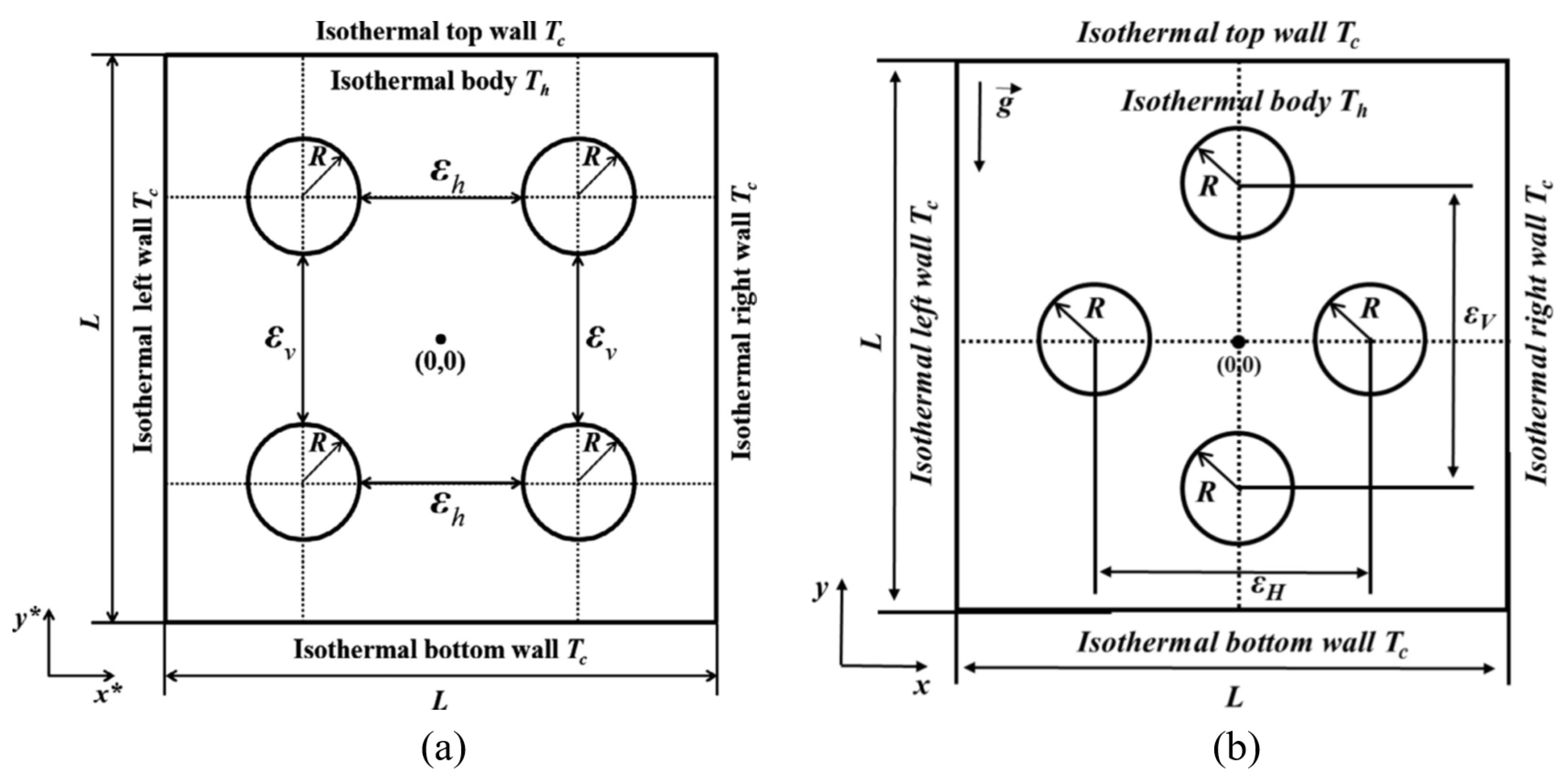
The previous studies on the NCHT in a horizontal closed rectangular enclosure with more than two inner circular objects are very limited. Only four such studies have been found [85,86,87,88], which considered four inner CCs of the same size in two different arrangements (in-line and staggered arrangements), as shown in Figure 19. The in-line arrangement was considered in [85,86,87] while the staggered arrangement was considered in [88]. All these four studies were carried out numerically using the IBM/FVM over 10 3 R a 10 6 with P r = 0.7 , assuming that the NCHT is 2D, laminar, and unsteady, and all cylinders are of the same size ( r = 0.1 ).
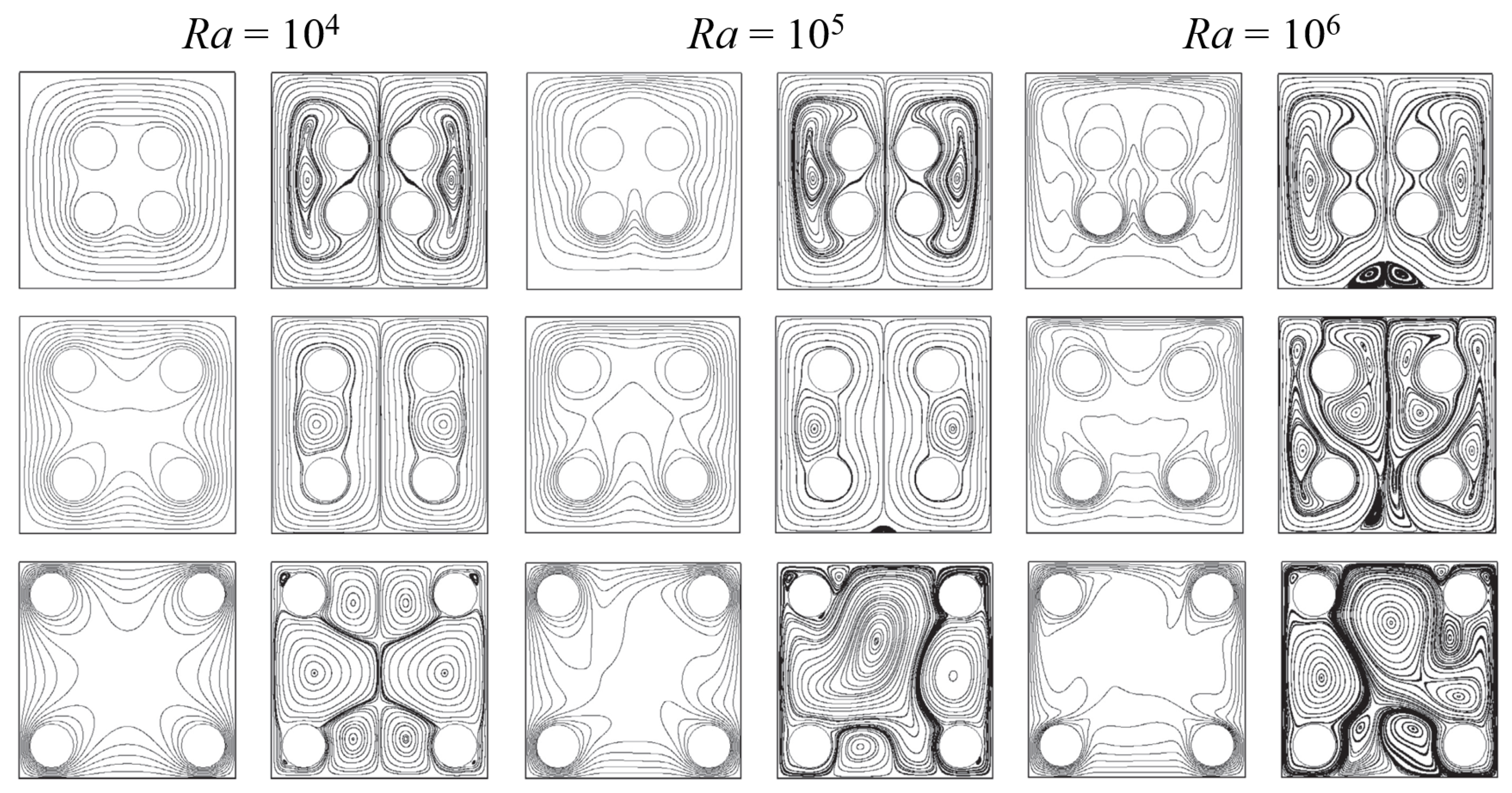
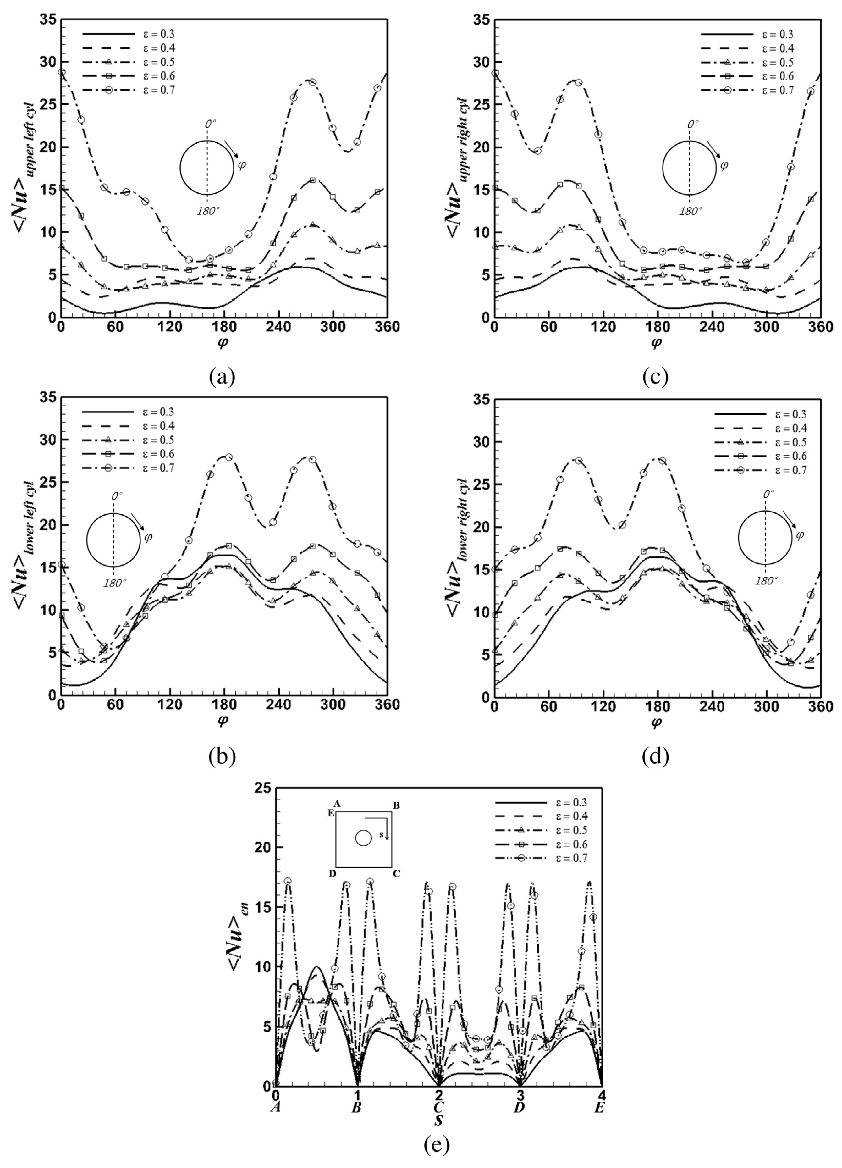
Park et al. [87] examined the effects of the location of the four in-line cylinders in the square enclosure on the heat transfer and fluid flow when they moved along the diagonal centerlines of the enclosure. The steady state isotherms and streamlines in the enclosure when the cylinders are at various center-to-center distances ( ε ) at R a = 10 4 , 10 5 , and 10 6 , respectively, are presented in Figure 20 [87]. The corresponding distributions of the local N u on the surfaces of the four cylinders and the enclosure wall are also presented for R a = 10 5 in Figure 21 [87]. The results show that, for all the cases considered, the flow and thermal fields eventually reached steady state when R a 10 4 , but became unsteady when R a 10 5 depending on the cylinders’ positions, which results in the strong dependence of the distributions of the local N u along the four cylinders and the enclosure walls on R a and ε . It was also found that, when R a 10 5 , the time and N u ¯ s , e n generally increases with increasing ε , but when R a = 10 6 , this is different. Seo et al. [85] conducted a similar study, but focusing on the effect of the horizontal distances ( ε h ) between the four in-line cylinders over 0.1 ε h 0.5 when the vertical distances of the cylinders are at ε v = 0.3 . At a relatively high R a ( 10 6 ), they investigated the flow regime transition from steady to unsteady state. It was found that N u on both the cylinders and the enclosure walls increase as R a and ε h increase and empirical correlations for heat transfer in terms of ε h and R a were developed. Seo et al. [86] subsequently examined the effect of the vertical distances ( ε v ) between the four in-line cylinders and compared with those when the cylinders change distances diagonally [87] and horizontally [85]. Again, at a relatively high R a ( = 10 6 ), the variation in the flow and thermal structures, together with the corresponding heat transfer characteristics, were examined in relation to the flow regime transition from steady state to unsteady state. The results show that N u on both the cylinders and the enclosure walls increase as R a and ε v increase, similar to that of [86,87], although there are quantitative differences.
Mun et al. [88] studied the NCHT in a cold square enclosure with four staggered (in diamond array) hot inner cylinders to examine the effects when the cylinders change their horizontal and vertical distances unequally over 0.3 ε h 0.7 and 0.3 ε v 0.7 , respectively. They found that, similarly, when R a 10 5 , the natural convection does not present time-independent characteristics when the cylinders’ distances change, but when R a = 10 6 , time-dependent characteristics occur for the majority of the cylinders’ distances considered. Again, it was found that N u on both the cylinders and the enclosure walls increase as R a and ε v and ε h increase. It was further revealed that, when R a increases, the geometrical arrangement of the cylinders has little effect on the heat transfer, but with the increase in ε v and ε h , it has influence on the heat transfer due to the changes in the characteristics of the unsteady flow and the gap between the cylinders and walls.
There are several previous studies which studied the natural convection flow and heat transfer in a horizontal rectangular enclosure with more than two inner CCs [89,90,91]. However, the enclosure surfaces were generally insulated and the natural convection was produced by the temperature difference between that on the cylinder surfaces and the surrounding medium (air or water in experimental studies) in the enclosure, and the top boundary was not closed, but open to the ambient. Such studies particularly focused on the natural convection boundary layers and buoyant plume around an array of heated cylinders. As the cases considered in these studies are different from the scope of this review, the details of such studies are not presented here.

4.1.2. Square Objects

One Square Cylinder

From the literature, it was found that there have been 15 previous studies which investigated the NCHT in a horizontal closed rectangular enclosure with an inner square cylinder (abbreviated as “SC” hereafter) at different temperatures or heated with heat flux [20,92,93,94,95,96,97,98,99,100,101,102,103,104,105]. All of them are numerical studies with the assumption of laminar flow. Only one study [98] used 3D numerical simulations and the remaining used 2D simulations. Nine studies investigated the unsteady NCHT and the remaining six investigated the steady NCHT. Different numerical methodologies have been used, including the FVM [94,95,96,97,98,99,100,101], FDM [20,102,103], LBM [92,93], and Chebyshev Spectral Collocation Method [104,105]. The majority of the studies used pure fluids including air and water as the medium, but one study used power-law fluid [96] and four studies used nanofluids (Cu-water [95,100,102] and Ag-water [101]) as the medium. A summary of these previous studies is presented in Table 4.
The four cases most studied in the 15 previous studies are illustrated in Figure 22. There are four studies which considered other different cases [100,101,104,105].
For Case 1, Dash et al. [93] examined the effect of a hot inner SC at different horizontal and diagonal eccentric locations in a cold square enclosure on the NCHT in the enclosure over 10 3 R a 10 6 . Their obtained steady state isotherms and streamlines show that, at lower R a ( 10 4 ), heat transfer is mainly dominated by conduction where the isotherms and streamlines are symmetrically distributed, but when R a 10 5 , convective heat transfer becomes prominent and thermal plumes are present. When the cylinder is eccentric, N u strongly depends on R a and the eccentricity ( χ ). Dash et al. [92] conducted a similar study, but focused on the effect of the vertical eccentricity of the SC. Ali et al. [102] also studied the NCHT in a cold square enclosure with a hot inner SC for Case 1 over 10 3 R a 10 6 . But in their study, the medium is nanofluid (Cu-water) with the concentration of nanoparticles over 0 ϕ 0.2 .
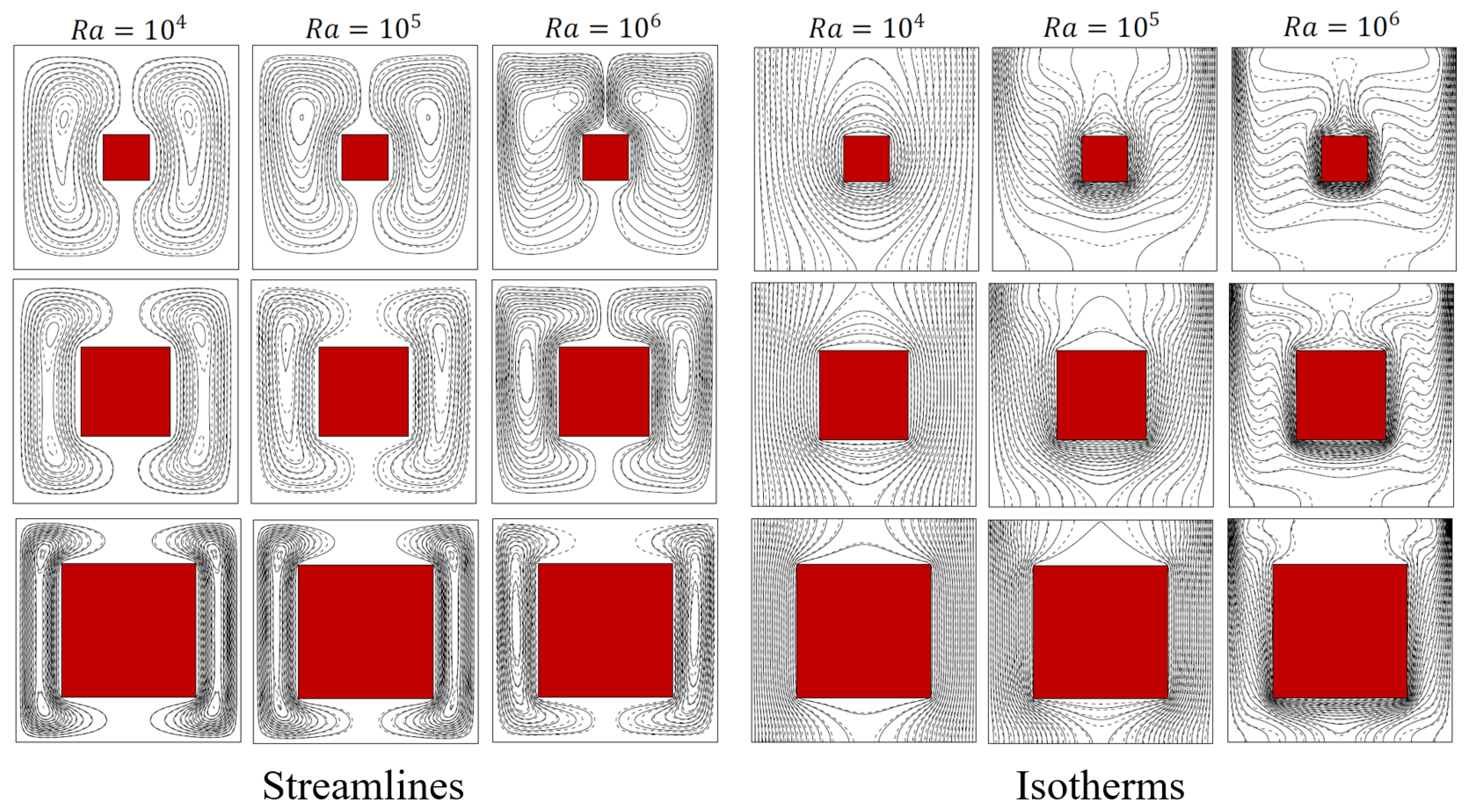
Two studies [94,95] investigated the NCHT in a horizontal closed rectangular enclosure with a single heated inner SC in Case 2 where the top and bottom walls of the enclosure are insulated while the vertical walls of the enclosure are at lower temperature. Boulahia et al. [95] studied the NCHT of nanofluid (Cu-water) with the concentration of nanoparticles over 0 ϕ 0.05 in a square enclosure with a heated inner SC which changes size over 0.2 A s 0.6 . Their obtained steady state isotherms and streamlines are presented in Figure 23. Their results show that R a , A s , and ϕ have significant effects on the heat transfer, with the increase in R a or A s resulting in larger N u but the effect of ϕ is complicated. Bouafia et al. [94] studied the transition from stability to instability of the unsteady NCHT in Case 2 with the heated inner SC of the size A s = 0.125 located at one-fourth of the enclosure height for three different enclosure aspect ratios ( A = 1 , 2 and 4) over 1.4 × 10 3 6.8 × 10 6 with air as the medium. Their results show that, for A = 1 and 4, the first transition occurs through a supercritical Hopf bifurcation, with shear and buoyancy-driven instabilities, while for A = 2 , the flow undergoes a pitchfork bifurcation that leads to an asymmetric steady state which in turn becomes periodic. It was also found that, in both cases, the flow is significantly deflected in the direction of one vertical wall and instabilities are shear layers type.
The previous studies with Case 3 shown in Figure 22c were carried out by Ha etal. [97,98,99]. Oh et al. [99] studied the 2D steady laminar NCHT when the inner square was heated with flux quantified by the temperature–difference ratio 0 Δ T * 50 when R a   10 3 and 10 4 , P r = 0.7 and K * = 1 where K * is the thermal conductivity ratio of solid and fluid. Their results show that, for a specific R a , when Δ T * increases, the average N u at the hot wall ( N u h ¯ ) decreases linearly but that at the cold wall ( N u c ¯ ) increases linearly, and N u h ¯ = N u c ¯ Δ T * . Ha et al. [97] continued this study by extending the governing parameters K * and P r when they considered three different fluids as the medium (sodium: K * = 1.71 and P r = 0.0112 ; air: K * = 5630 and P r = 0.707 ; and water: K * = 240 and P r = 5.83 ) over 0.25 Δ T * 50 when R a = 10 3 and 10 4 . They found that the flow and heat transfer are influenced by Δ T * , R a , and K * and some similar conclusions obtained by Oh et al. [99] can also be drawn. As these two previous studies only considered the 2D steady laminar NCHT for Case 4, Ha et al. [98] carried out a 3D steady laminar NCHT for Case 4 due to its practical significance. In their study, adiabatic boundary conditions were applied on two vertical walls (front and rear) in the longitudinal direction and the closed enclosure was a cube. They only considered K * = 1.72 and Δ T * = 2.5 and 25, still at R a = 10 3 and 10 4 with P r = 0.0112 . They found that the presence of the heat-generating SC produces very complex flow and heat transfer behavior, and Δ T * = 2.5 and R a have significant effects on the heat transfer.
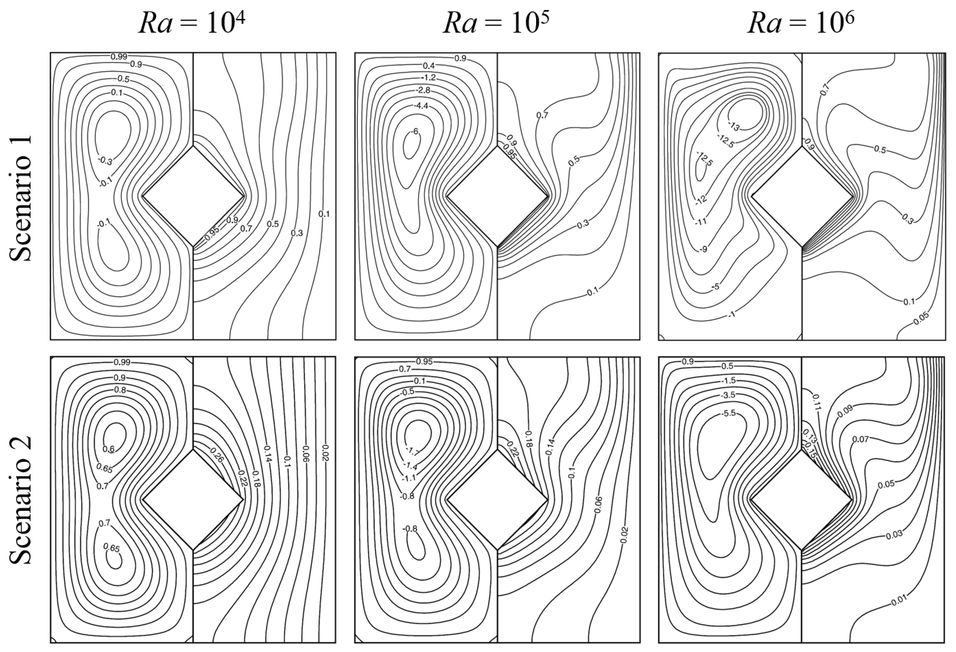
For Case 4 shown in Figure 22d, three previous studies were found. De et al. [103] considered two scenarios; Scenario 1 assumes that the inner SC is at temperature T h and Scenario 2 assumes that the cylinder is heated with uniform flux q . The study investigated the effects of the enclosure aspect ratio and the vertical location of the cylinder for both scenarios over 10 3 R a 10 6 . The authors introduced the concept of heat function to trace the path of heat transport and showed that the NCHT features are significantly different between the two scenarios, as demonstrated by the steady state streamlines and isotherms inside the enclosure, as shown in Figure 24. It was further found that, when the enclosure aspect ratio and the location of the cylinder change, the flow pattern and thermal stratification as well as the overall heat transfer will vary. Dutta et al. [20] conducted a similar study with P r = 0.71 and found similar results. They also compared the results for the SC case to that for the CC case and noted that the differences between the two cases are significant. Sairamu et al. [96] studied the case with power-law fluid as the medium, over 71 R a 10 7 , 0.71 P r 100 , and 0.2 n 1.5 where n is the power-law index. They examined the effect of the vertical location of the cylinder ( y = 0.25 , 0, 0.25, all at x = 0 ). The results show that, overall, the influence of the power-law fluid behavior is strongly modulated by R a , P r , and y and an empirical correlation was developed for the average N u in terms of R a , P r , n, and y for each scenario.
In addition to the Cases shown in Figure 22, four previous studies also considered other cases with different boundary conditions applied on the enclosure walls and the inner SC. Ha et al. [104] considered the case in which the two vertical walls and the bottom wall of the 2D square enclosure are adiabatic while the top wall is at a lower temperature T c , with the inner SC at four different thermal boundary conditions (higher temperature T s = T h , same cold temperature T s = T c , neutrally isothermal temperature ( T s = ( T h + T c ) / 2 ), and adiabatic ( T s / n = 0 )). They assumed that the flow and heat transfer are 2D, laminar, and unsteady and used the Chevyshev spectral collocation method in their numerical simulations. Their results show that, when R a is small, a steady flow can be reached and the flow and temperature distributions are symmetrical, but at the intermediate R a , although a steady flow can still be reached, the symmetry breaks down, whereas when R a is high, the flow becomes time-dependent, and the time-averaged distributions of the flow and temperature approach the symmetric pattern again. It was further found that R a , for the flow to become non-symmetrical and time-dependent, is influenced by the thermal boundary conditions on the cylinder, and the time- and N u ¯ s also strongly depend on the thermal boundary conditions on the cylinder. Lee et al. [105] investigated the 2D unsteady laminar NCHT in a square enclosure with an inner SC of the size A s = 1 / 3 which is heated by flux ( q ). The two vertical enclosure walls are adiabatic and the top and the bottom walls are at a lower temperature ( T c ) and a higher temperature ( T h ), respectively. The numerical simulations were carried out for P r = 0.7 , 10 3 R a 10 6 , temperature difference ratio ( 0 Δ T 25 ), and thermal conductivity ratio between solid and fluid ( 0 k 50 ), respectively, using the Chevyshev spectral collocation method. Their results show that, when Δ T is small (≤0.25), the effect the cylinder is small and the fluid flow and temperature fields in the enclosure are mainly governed by the temperature difference between the bottom hot and top cold walls, so a steady flow and heat transfer can eventually reach; however, with the increase in Δ T from 2.5, the effect of the cylinder becomes strong, which makes the fluid flow and temperature fields unstable, and for high R a (≥ 10 5 ), the flow and heat transfer become time-dependent, leading to the surface-averaged N u at the bottom hot and top cold walls ( N u ¯ h and N u ¯ c ) chaotic with large amplitude. They noted that the effects of k strongly depend on both R a and Δ T and vary significantly for different combinations of R a and Δ T . The case considered by Sheremet et al. [100] in their 2D steady laminar numerical study is a complex one, where the top wall of the square enclosure is at a lower temperature T c and a segment (with dimensionless length h) of both the vertical and horizontal walls at the left bottom corner of the enclosure is also at T c while the remaining walls of the enclosure are adiabatic. The inner SC is at a higher temperature T h . The medium in the enclosure is nanofluid. Their numerical simulations were carried out using the FVM over 10 3 R a 10 6 , solid volume fraction of nanoparticles ( 0 ϕ 0.05 ), cylinder size ( 0.2 A s 0.6 ), and 0.25 h 0.75 , respectively. The results show that an increase in R a results in a larger N u but a smaller average Bejan number due to an enhancement in fluid friction; an increase in ϕ increases the average N u and Bejan numbers and average total entropy generation; an increase in A s leads to a smaller N u , but larger average Bejan number and average total entropy generation; and all these average parameters increase when h is increased due to the increase in the heat sink surface. Another complex case is considered by Umadevi and Nithyadevi [101] where the top wall of the 2D square enclosure is adiabatic, the right vertical wall is at a lower temperature T c , the bottom wall is at a higher temperature T h , and the left vertical is heated sinusoidally with height. The medium is Ag-water nanfluid, with 0 ϕ 0.2 . The 2D steady laminar numerical simulations were conducted using the FVM for 0.25 A s 0.75 , 1 k 5 , and 0 Δ T 50 , all at R a = 10 6 . They found that increasing A s reduces N u due to the insufficient space inside the enclosure, but the increases in Δ T and ϕ enhance N u .

Multiple Square Cylinders

Nine previous studies were found which considered the NCHT in a horizontal closed rectangular enclosure with multiple square cylinders at different heating conditions. Four studies considered two SCs [106,107,108,109], two studies considered four SCs [110,111], and the remaining studies considered more than four SCs [112,113,114]. All these studies are numerical, with six assuming 2D steady laminar flow and heat transfer [108,109,110,111,113,114] and the remaining three assuming 2D unsteady laminar flow and heat transfer. The majority used the FVM [106,107,108,109,113,114], while Rahimi et al. [110] used the LBM, Usman et al. [111] used the FEM, and Aly et al. [112] used the Incompressible Smoothened Particle Hydrodynamics Method, respectively.
Figure 25 presents the cases considered by the four studies concerning two SC [106,107,108,109]. In the study by Hidki et al. [106], the two identical inner SCs generate uniform volume powers represented by two independent R a values ( R a 1 and R a 2 , which are R a on Cylinders 1 and 2, respectively), with R a 1 = 10 3 , 10 5 and 10 7 over 10 3 R a 2 10 7 for each R a 1 . The right wall of the air-filled ( P r = 0.71 ) square enclosure is cooled, while the other walls are adiabatic, as shown in Figure 25a. For comparison, this study also considered the cases with two identical CCs and with two identical elliptic cylinders (abbreviated as “EC” hereafter). It was noted that the streamlines for the two SCs configuration are almost similar to the two CCs configuration for all considered R a 1 and R a 2 ; when Rayleigh numbers increase, the flow become intensified and the isotherms are more concentrated in the cylinder that corresponds to the highest Rayleigh numbers; when the cylinders generate the same amount of heat ( R a 1 = R a 2 ), cylinder 1 is always the hottest; the mean temperatures of the cylinders show that the increase in the amount of heat in one cylinder allows for the cooling of the other; and in order to obtain a good cooling of both cylinders, the square shape should be chosen. Hidki et al. [107] extended the work by examining the effect of the size and vertical position of two heat-generating SCs in the air-filled square enclosure for the case shown in Figure 25a for R a = 10 6 . Each cylinder changes its size from 0.1 to 0.4 and at three different heights ( ( x 1 = 0.25 , y 1 = 0.25 ) , ( x 2 = 0.25 , y 2 = 0 ) , and ( x 3 = 0.25 , y 3 = 0.25 ) ) and is heated with the same flux. They found that the size and vertical position of the two SCs significantly affect the flow and heat transfer, the isotherms are more concentrated in the largest cylinder, the maximum temperature increases rapidly with the size of both cylinders, and to achieve the excellent cooling of the two cylinders, they should not be located above the middle height of the enclosure. In addition to that for the vertical positions of the two SCs, Hidki et al. [108] also examined the effect of the horizontal positions of the two SCs of the same size A s = 0.25 , as shown in Figure 25b with both R a 1 and R a 2 over 10 3 10 6 . Their results show that the isotherms are more concentrated in the cylinders, particularly in the cylinder corresponding to the higher R a , where the maximum temperature of a specific cylinder increases with the associated R a , whereas it decreases generally by increasing the heat released by the other cylinder, for adequate cooling of the cylinder that generates the most heat, it must be as close as possible to the coldest wall, indicating that when R a H R a L , the horizontal position configuration shown in Figure 25a can provide good cooling of the electronic devices, while for R a H R a L , the vertical position configuration shown in Figure 25b is recommended. Pordanjani et al. [109] studied the effect of magnetic field on the steady state natural convection of Al2O3-water nanofluid inside a square enclosure with lower sinusoidal temperature distribution applied on the two vertical side walls while the top and bottom walls were insulated and with two inner heated SCs of the same size over the parameter ranges 0.1 A s 0.4 , 0 H a 50 , 10 3 R a 10 6 , 0 φ 0.06 , and 0 γ 180 o , where H a , φ and γ are the Hartmann number, concentration of nanoparticles and magnetic field angle, respectively. The two cylinders are at the fixed locations (( x 1 = 0.25 , y 1 = 0 ) and ( x 2 = 0.25 , y 2 = 0 )). The results show that, when H a or A s was increased, N u decreased for all φ considered, but increasing φ , γ , or R a enhanced N u .
Both Rahimi et al. [110] and Usman et al. [111] studied the NCHT in a horizontal closed rectangular enclosure with four SCs at different heating conditions. In [110], the two vertical side walls are at different temperatures ( T h and T c ) and the top and bottom walls are insulated. Four different scenarios were considered when the four SCs of the same size and located at ( x 1 = 0.25 , y 1 = 0.25 ), ( x 2 = 0.25 , y 2 = 0.25 ), ( x 3 = 0.25 , y 3 = 0.25 ), and ( x 4 = 0.25 , y 4 = 0.25 ) are heated/cooled differently, as shown in Figure 26a. The medium in the enclosure is DWCNTs–water nanofluid. The numerical simulations were carried out over 2 × 10 6 R a 8 × 10 6 and 0.01 φ 0.4 . The study found that the arrangement of the SCs strongly affects the average N u and total entropy generation while N u has direct relationship with R a and φ , although the total entropy generation has direct and reverse relationship with R a and φ , respectively. The case considered by Usman et al. [111], as shown in Figure 26b, is on the steady heat and mass transfer of Magnetohydrodynamic (MHD) flow in a closed square enclosure with the top wall of the enclosure heated and the remaining walls cooled. The four SCs are of the same size and their locations are fixed for all numerical simulations, with the bottom two cylinders heated and the top two cooled. The effects of the Hartman number, buoyancy number, heat source, and radiation were examined for R a = 10 4 and P r = 6.2 . The results show that the total N u increases with increasing thermal radiation but decreases with increasing heat generation, and better heat transfer is achieved when the bottom SCs are heated.
The three previous studies involving more than four inner SCs considered diversified scenarios in which a wide range of cylinders are arranged in complex ways. In the study by Aly et al. [112], three different arrangements of relatively small SCs are considered, i.e., one column of seven SCs on the left half of the square enclosure which is heated/cooled on the sidewalls and is adiabatic on the top and bottom walls and filled with nanofluid; two columns of seven SCs (totaling 14) each on the left/right half of the enclosure; and three columns of seven SCs (totaling 21) at the left and right half and at the middle of the enclosure, respectively. It was found that the number of cylinders has significant effects, with its increase leading to an increase in the maximum of the velocity fields and increase in the hot or cool areas inside the enclosure, the effects of adding nanoparticles concentration are smaller than that of the presence of the cylinders, and the average N u is larger at the case of the cooling cylinders compared to the heating cylinders. The cases studied by Garoosi et al. [114] are even more complex. They considered 10 cases with numbers of SCs from four to nine and the sizes, locations, and heating/cooling conditions varied significantly. All walls of the square enclosure, which is filled with nanofluid (Cu, Al2O3 and TiO2 nanoparticles), are adiabatic and some of the inner cylinders are heated and the others are cooled. The numerical simulations are over 10 4 R a 10 6 , 0 φ 0.05 , 25 nm d p 145 nm ( d p is the size of nanoparticles, and 294 K T a v e 324 K ( T a v e is the nanofluid average temperature) for the different numbers, sizes, and locations of the heated/cooled SCs. The results show that the locations of the cylinders have the most significant influence on N u , and at low R a , the particle distribution is fairly non-uniform while, at high R a , it remains almost uniform with an optimal φ at each R a in which the maximum obtainable N u occurs. It was also found that reducing d p and increasing T a v e , R a , and the number of cylinders increase N u . Hu et al. [113] studied the steady NCHT in a square enclosure filled with fluid of P r = 0.71 with the left/right vertical side walls heated/cooled and with different numbers of small inner SCs. The SCs are evenly distributed in the enclosure and their number (N) changes from 1 to 64, with their sizes varied accordingly. Their numerical simulations also include the change in the fluid and solid thermal conductivity ( K r = 0.1 , 1.0 and 10.0) and solid-to-fluid volume ratio ( 0.36 γ 0.64 ) for 10 3 R a 10 7 . The results show that the average N u increases when R a and K r increase, but decreases when γ and N increase.

4.1.3. Objects in Other Shapes

Elliptic Cylinder

Elliptic cylinders are another type of commonly used IOs within a closed enclosure to produce NCHT inside the enclosure. From the literature, 13 previous studies were found which studied the NCHT in a horizontal closed rectangular enclosure with inner heated ECs. Among them, eight studies used a single EC [25,115,116,117,118,119,120,121], four used two ECs [106,122,123,124], and only one used more than two ECs [125]. All these studies are numerical and assumed laminar flow, and only two carried out 3D numerical simulations [25,121] while the remaining studies carried out 2D numerical simulations. Only three studies assumed that the flow and heat transfer are steady [115,116,117] and the remaining studies dealt with unsteady flow and transfer. The IBM/FVM was the most used numerical method [25,118,119,121,122,123,124], and FEM [116,117], FVM [106], FDM [120], and LBM [115] were also used.
The cases considered by the eight previous studies which used a single inner EC are shown in Figure 27. The parameters representing the geometry of an EC are the major and minor axis lengths ( 2 a and 2 b , respectively) and the inclined angle of the major axis with respect to the horizontal line ( ψ ). A summary of these previous studies is presented in Table 5.
Bararnia et al. [115] examined the effects of R a and the vertical position of a heated inner EC on the NCHT for the case shown in Figure 27a and found that they are significant. Raman et al. [119] examined the effects of R a and the heated EC size ( A R = b / a ), also for the case shown in Figure 27a, and found that the effect of A R is remarkable at higher R a , and the N u ¯ s increases with increasing A R and R a . Hashemi et al. [116] studied the flow and heat transfer of a micropolar nanofluid (CuO-water) in a radiative porous enclosure under MHD (Magnetohydrodynamic) effects with an inner elliptical heater by using the Koo–Kleinstreuer–Li (KKL) model to simulate the effects of Brownian motions on the dynamic viscosity and thermal conductivity of the micropolar nanofluid, as shown in Figure 27b. The numerical simulations were carried out over 10 R a 1000 ( R a is the Darcy–Rayleigh number), 0 H a 50 ( H a is the Hartman number), 0 ϕ 0.04 ( ϕ is volume fraction), 1 H 1000 (H is interface heat transfer coefficient), 0.1 K r 10 ( K r is thermal conductivity ratio), 0.1 ϵ 0.9 ( ϵ is porosity), 0 Δ 2 ( Δ is vortex viscosity parameter), and 0 R d 2 ( R d is radiation parameter). They showed that increasing H results in the growth of strength of flow and micro-rotations, increased N u through the fluid phase and decreased N u through the solid phase; an increase in H a leads to reduced strength of flow and particles’ micro-rotations; thus, reduced N u as well; increasing R d strengthens the flow and micro-rotations of particles and the effect R d becomes stronger when R a is higher; increasing ϕ increases N u through the solid phase; and increasing Δ reduces N u through the fluid phase. Roy [120] studied the natural convection of a nanofluid (Al2O3-water) in a horizontal closed square enclosure and a heated cylinder with different shapes (circular, elliptical, or rectangular) for the case shown in Figure 27c to examine the effects of ϕ , R a , and the shape of the inner cylinder and found that the effects are significant. Liao et al. [118] examined the effects of A R and the orientation angle of the cylinder ( ψ ) on the NCHT for the case shown in Figure 27d. The values of A R are determined by fixing the perimeters of all ECs using π [ 3 ( a + b ) ( 3 a + b ) ( a + 3 b ) ] . It was found that the local N u along the hot surface is more uniform for circular-like cylinders than its elongated cylinder counterpart, the average N u has weak dependence on A R , an increase in ψ results in larger mean N u on both cylinder and enclosure walls and the influence of A R is only significant at ψ = 45 , and a slender EC generates higher N u compared to that with a CC. A similar study was carried out by Jelita et al. [117] who also found that the effects of A R , R a , and ψ are significant. Seo etal. [25] investigated the 3D NCHT for the case shown in Figure 27e by conducting 3D numerical simulations. Periodic boundary conditions were applied on the vertical walls in the longitudinal direction. The study focused on the size effects of both circular and elliptical cylinders and concluded that they are significant. The size (a and b) was determined in the same way as Liao et al. [118] did. Seo et al. [121] extended this study by examining the effect of the orientational angles ( ψ ) of the elliptical cylinder with 3D numerical simulations, as shown in Figure 27f, and found that the heat transfer characteristics were strongly affected by ψ .
The cases investigated by the four studies which considered two inner cylinders involving at least one EC are shown in Figure 28. All these four studies were carried out by 2D numerical simulations using the IBM/FVM or FVM under the assumption of unsteady and laminar flow. The case studied by Cho et al. [123] is shown in Figure 28a, where the NCHT is in a horizontal closed cold square enclosure with two hot elliptical cylinders vertically aligned, at ( x 1 = 0 , y 1 = 0.25 ) and ( x 2 = 0 , y 2 = 0.25 ). Simulations over the range of 10 4 R a 10 6 and 0.25 A R 4.0 indicated that the flow regime transition at R a = 10 6 , from steady to unsteady, is significantly affected by A R . When R a 10 5 , increasing the aspect ratio ( A R ) of the upper elliptical cylinder leads to a rise in the time and N u ¯ s , e n . For R a = 10 6 , minor enhancements occur for A R = 0.5 in the upper elliptical cylinder and A R = 2.0 in the lower elliptical cylinder compared to two CCs, reflecting the effect of A R on heat transfer performance. Hidki et al. [106] studied the case with two inner heated ECs, as shown in Figure 28b. They also considered square and CCs to make a comparison. The enclosure is square and filled with air ( P r = 0.71 ), and the two cylinders have the same surface for different geometric shapes and are horizontally aligned, at ( x 1 = 0.25 , y 1 = 0 ) and ( x 2 = 0.25 , y 2 = 0 ). These two cylinders generate uniform volume powers represented by two Rayleigh numbers ( R a 1 and R a 2 ). The effects of R a 1 and R a 2 , both between 10 3 and 10 7 , and the effect of the cylinders’ geometry on the temperature and flow fields, as well as on the local heat transfer, were examined. It was found that the streamlines for the square and CC configurations are almost similar for all considered values of R a 1 and R a 2 ; increasing R a 1 and R a 2 strengthens the flow in the enclosure, and the isotherms are more concentrated in the cylinder that corresponds to the highest R a ; when R a 1 = R a 2 , cylinder 1 is always the hottest; increasing the amount of heat in one cylinder allows for the cooling of the other; and to obtain a good cooling of both cylinders, the square shape should be chosen. Cho et al. [122], as shown in Figure 28c, analyzed NCHT within a square enclosure containing one circular and one elliptical cylinder in a vertical configuration, focusing on 10 4 R a 10 6 and varying the aspect ratio ( A R ) of the elliptical cylinder between 0.25 and 4.0 . Two configurations of the cylinders were considered. In the first configuration, the CC is located above at ( x 1 = 0 , y 1 = 0.25 ) while the EC is located below at ( x 2 = 0 , y 2 = 0.25 ) and in the other configuration, the positions of these two cylinders are just swapped. The results showed that, at R a = 10 6 , the flow and heat transfer become unsteady for all configurations involving the lower elliptical cylinder and the upper elliptical cylinder, except at A R = 2.0 and A R = 4.0 . The aspect ratio dictates the transition from unsteady to steady flow regimes. Furthermore, for the upper elliptical cylinder at A R = 0.5 , the time and N u ¯ s , e n increases only marginally compared to the case with two CCs. Park et al. [124] conducted a similar study for the similar configurations as shown in Figure 28d, but in this case, the heated inner EC can rotate so the effects of the position and orientation angle ( ψ ) of the elliptical cylinder can be examined over 10 4 R a 10 6 and 0 ψ 90 . The results indicate that, when R a rises to 10 6 , the flow and heat transfer become unsteady for all setups involving the lower elliptical cylinder and the upper elliptical cylinder, except at ψ = 90 . The transition between unsteady and steady states depends on the flow orientation and the spacing between the upper cylinder and the enclosure’s top wall, influenced by ψ . Specifically, at R a = 10 6 , in the case of the upper elliptical cylinder with ψ = 0 , the time and N u ¯ s , e n increase only marginally relative to the configuration with two CCs.
Only one previous study was found which investigated the NCHT in a horizontal closed cold rectangular enclosure with more than two inner heated ECs. Seo et al. [125] studied the case in which four identical heated ECs are within a cold enclosure, located at ( x 1 = 0.25 , y 1 = 0.25 ) , ( x 2 = 0.25 , y 1 = 0.25 ) , ( x 3 = 0.25 , y 1 = 0.25 ) , and ( x 1 = 0.25 , y 1 = 0.25 ) , respectively, with 2D numerical simulations under the assumption of laminar and unsteady flow using IBM/FVM. The numerical simulations were carried over 10 4 R a 10 6 and 0.25 A R 4.0 with P r = 0.7 . When R a 10 5 , the flow and heat transfer remain steady and exhibit symmetry about the vertical centerline of the enclosure, irrespective of A R . At R a = 10 6 ; however, the system transitions to unsteady states that depend on A R . This leads to an increase of approximately 4.38% in the time- and surface-averaged N u on the cylinder surfaces and 5.24% on the enclosure surfaces at A R = 4.0 compared to A R = 1.0 , highlighting the significant influence of A R on heat transfer characteristics.

Rectangular Cylinder

Six previous studies were found which studied the NCHT in a horizontal closed rectangular enclosure with one or more inner rectangular cylinders at different heating conditions [114,120,126,127,128,129]. All of them are numerical, assuming 2D and laminar flows. Only two [114,128] assumed steady flow and heat transfer and the remaining assumed unsteady flow and heat transfer. The numerical methods used include LBM [126,127,129], FVM [114], FEM [128], and FDM [120].
Four studies [120,126,127,128] considered only one inner rectangular cylinder. Lu et al. [126] studied the unsteady NCHT in a horizontal closed cold rectangular enclosure with one inner heated rectangular cylinder located at the center of the enclosure over 10 3 R a 10 7 and 0.1 l 0.9 (where l is the dimensionless length of the rectangular cylinder) with d = 0.2 (d is the dimensionless width of the rectangular cylinder) and P r = 0.71 . The results show that the flow and heat transfer behaviors can be classified into eight buoyant regimes, i.e., four steady regimes, two periodic regimes, one multiple periodic regime, and one chaos regime. However, this study did not provide the results for N u . Sheikholeslami et al. [127] studied the unsteady magnetohydrodynamic NCHT of CuO–water nanofluid ( P r = 6.8 ) in a square enclosure, containing a heated rectangular cylinder. The top and bottom walls of the enclosure are adiabatic, while the two vertical sidewalls are cold. The cylinder, with l = 0.5 and d = 0.1 , is located at the center of the enclosure. Their study assessed the effects of the Hartmann number ( 0 H a 10 ), nanoparticle volume fraction ( 0 ϕ 0.04 ), and R a ( 10 3 R a 10 5 ) on flow behavior, heat transfer, and entropy generation. The results indicate that both N u and the dimensionless entropy generation number increase with increases in R a and ϕ , but decrease as H a increases. Roy [120] studied the unsteady NCHT of a nanofluid between a square enclosure and a heated rectangular cylinder (the cases with a heated circular and a heated elliptical cylinder were also considered for comparison). The cylinder is at the center of the enclosure, with l = 0.5 and d = 0.25 . The top wall of the enclosure is adiabatic and the remaining walls are cold. The numerical simulations were carried out over 10 3 R a 3 × 10 4 and 0 ϕ 0.1 , with different nanofluids (with Ag, Cu CuO, Al2O3, and T i O2 nanoparticles) to examine the effects of R a , ϕ and the types of nanofluids. The results show that, when R a and ϕ increase, the streamlines strengthen, and N u at the inner cylinder and enclosure is approximately linearly increased with ϕ while exponentially increased with R a . The comparison indicated a reduction in N u as the inner shapes become circular, elliptical, and rectangular. In the study by Olayemi et al. [128], the center-located heated inner rectangular cylinder is inclined with ψ between 0° and 90°. The square enclosure is filled with air and its walls are cold. The rectangular cylinder has the dimensionless width of d = 0.1 but the length varies over 0.1 l 0.7 . It has been found that over 0.1 l 0.7 and 10 2 R a 10 6 , N u increases with increasing l and R a , and in general ψ improves N u except at l = 0.1 , where the average N u reduces beyond ψ = 45° for R a values considered.
Two previous studies were found which investigated the NCHT in a horizontal closed enclosure with two inner rectangular cylinders at different heating conditions [114,129]. Garoosi et al. [114] studied the case where the square enclosure walls are adiabatic, and two rectangular cylinders with the same size ( l = 0.4 and d = 0.1 ) are placed vertically at ( x 1 = 0.3 , y 1 = 0 ) and ( x 2 = 0.3 , y 2 = 0 ) and one is heated and another is cooled. The media in the enclosures are nanofluids (with Cu, Al2O3, and T i O2 nanoparticles) with the sizes of nanoparticles over 25 nm d p 145 nm and volume fractions over ( 0 ϕ 0.05 ). The numerical simulations were carried out over 10 4 R a 10 7 . The results show that there is an optimum ϕ where the maximum N u is achieved, smaller nanoparticles improve heat transfer, and the optimum ϕ enhances when R a increases. An empirical correlation was also obtained for the total N u in terms of these governing parameters. Rahimi et al. [129] considered four configurations with different numbers of the inner rectangular cylinders and the heating conditions applied on them. For all four configurations, the top and bottom walls of the square enclosure are adiabatic and the two sidewalls are heated while the inner rectangular cylinders are cooled. The sizes of the cylinders are fixed ( l = 0.4 and d = 0.1 ) for each configuration. In the first configuration (Single Horizontal), only one rectangular cylinder is placed horizontally at the center of the enclosure while in the second configuration (Single Vertical), one rectangular cylinder is placed vertically at the center of the enclosure. In the third configuration (Double Horizontal), two rectangular cylinders are placed horizontally at ( x 1 = , y 1 = 0.25 ) and ( x 2 = 0 , y 2 = 0.25 ), while in the fourth configuration (Double Vertical), two rectangular cylinders are placed vertically at ( x 1 = 0.25 , y 1 = 0 ) and ( x 2 = 0.25 , y 2 = 0 ). The medium of the enclosure is DWCNTs–water nanofluids with 0.005 ϕ 0.02 . The numerical simulations were carried out over 10 3 R a 10 6 . The results show that the array of inner rectangular cylinders strongly affect the NCHT in the enclosure, with the Double Vertical configuration producing the largest average N u while the Single Horizontal configuration produces the smallest average N u . It was also found that N u has direct relationship with R a and ϕ , while the total entropy generation has direct and reverse relationship with R a and ϕ , respectively.

Triangular Cylinder

Three previous studies were found which studied the NCHT in a horizontal closed rectangular enclosure with an inner triangular cylinder (abbreviated as “TC” hereafter) at different heating conditions [130,131,132]. All of them are numerical, assuming 2D and unsteady laminar flows and using LBM.
Vijaybabu and Dhinakaran [130] studied the unsteady NCHT between a hot isosceles TC and a horizontal cold square enclosure under the influence of magnetic field for the case shown in Figure 29a. The study examined the effects of R a , Darcy number D a , Hartmann number H a , and orientation of the TC on the flow and heat transfer characteristics. The medium in the enclosure is Al2O3–water nanofluid with ϕ = 0.05 . The dimensionless base and height of the cylinder are 0.4 and 0.2, respectively, and the cylinder is oriented in two different configurations, namely apex-facing up and apex-facing down. The numerical simulations were carried out over 10 4 R a 10 6 , 10 6 D a 10 2 , 0 H a 50 , and porosity between 0.629 and 0.993, respectively. The results demonstrate that increasing permeability enhances fluid momentum, while a stronger magnetic field reduces the fluid’s kinetic energy. It was further found that the effects of D a and H a on N u are more pronounced in the apex-facing up configuration than in the apex-facing down configuration. Increasing H a also reduces the influence of permeability on heat transfer enhancement. Additionally, the mean N u for the apex-facing up configuration is consistently higher than for the apex-facing down configuration, across all values of R a , D a , and H a considered in this study.
In their study, Abdallaoui et al. [131,132] investigated unsteady NCHT in a horizontal square enclosure with an inner heated TC placed at different positions. The cylinder has a dimensionless height of 0.2 and width of 0.4, and is maintained at a higher temperature. The enclosure’s top and bottom walls are adiabatic, while the two sidewalls are at a lower temperature. The authors first considered the case when the heated TC is at different heights along the middle of the enclosure, at the locations of ( x 1 = 0 , y 1 = 0.25 ) (MT position: middle-top), ( x 2 = 0 , y 2 = 0 ) (MM position: middle-middle), and ( x 3 = 0 , y 3 = 0.25 ) (MB position: middle-bottom), respectively. The numerical simulations were carried out over 10 3 R a 10 7 with pure water ( P r = 7 ) and with the three different heights of the cylinder. The results show that the global flow intensity is strongly affected by the cylinder position as it is enhanced when the cylinder is moved downwards, although the boundary layer flow developed in the vicinity of the cylinder is less affected by the cylinder position, and the effect of the cylinder position on the heat transfer depends on R a ; as for the conduction regime and moderate convection, the MM position is the most favorable to the heat transfer, but for strong convection, the MB position is the most favorable. The study also developed an empirical correlation of the averaged N u . In their subsequent study [132], the inner heated TC is shifted to be closer to the left side of the enclosure, at three different heights (LB position: Left-Bottom; LM position: Left-Middle; and LT position: Left-Top), as shown in Figure 29b, with all other configuration features being the same as that in [131]. This study considered both pure water and water–silver nanofluids. The numerical study, conducted for 10 3 R a 10 7 and 0 ϕ 0.1 , showed that the position of the heating cylinder significantly impacts heat transfer and fluid flow. A rise in ϕ enhances the average N u for all positions, with the cylinder’s bottom position providing the best heat transfer performance and the top position the poorest.

Thin Plates

The NCHT in a horizontal closed enclosure with inner thin plates (abbreviated as “TP” hereafter) in different shapes, numbers, arrangements, and heating conditions have also been studied by some previous studies [133,134,135,136,137,138,139,140,141,142,143]. All these studies are numerical with the assumption of 2D laminar flow. Five studies [133,140,141,142,143] assumed steady state flows and the remaining studies assumed unsteady flows. The majority of the studies used FVM [133,134,141,142], FDM [137,138,139], and FEM [135,136,143] as the numerical methods, while one study [140] did not specify what numerical method was used. Five studies [133,134,135,136,137] considered a single inner TP, two [138,139] considered two inner TPs, and the remaining studies considered the inner TPs with other shapes and arrangements.
Öztop et al. [133] studied the NCHT in a horizontal closed enclosure with a single inner heated TP, which is either horizontally placed or vertically placed. The top and bottom wall of the enclosure are adiabatic and the two vertical sidewalls are at a lower temperature and the TP is at a higher temperature. For both placements of the plate, their lengths (l) change between 0.2 and 0.8, and their locations vary between x = 0.3 and x = 0.3 and between y = 0.3 and y = 0.3 . The numerical simulations were carried out over 10 4 R a 10 6 . The results show that, for both horizontal and vertical placements of the TP, the average N u increases with increasing R a and plate length, and the improvement in heat transfer for the vertical placement is higher than that for the horizontal placement. A similar study was carried out by Saravanan et al. [134] with the same configurations as that of [133]. However, the focus of the study is the interaction of surface radiation and NCHT in an air-filled square enclosure with the inner heated TP is centrally placed and does not change position. The numerical simulations were carried out over 10 5 R a 10 7 , 0.25 l 0.75 , and 0 ε 1 ( ε is emissivity), respectively. It was found that the presence of radiation makes the temperature distribution uniform within the enclosure and reduces the temperature differences between the insulated walls, although it also causes a more non-uniform temperature distribution on the insulated walls; increasing ε , R a , and l increases the overall N u ; the contribution of the convective mechanism to the overall N u increases with ε for the horizontal placement but decreases for the vertical placement; and N u is larger for the vertical placement, whereas the presence of radiation suppresses the above contrast in heat transfer. Similarly, Zadeh et al. [135] examined the effects of the flexibility of a heated inner TP on the NCHT inside the enclosure with the same configuration for the horizontal placement as considered in [133]. The flexibility of the plate is represented by the bending vertically. The numerical simulations were carried out over 10 4 R a 10 6 , 5 × 10 9 E τ 5 × 10 11 ( E τ is elasticity modulus), P r = 0.71 (air), 6.2 (water), and 200 (engine oil), 0.1 l 0.7 , and x = 0 , 0.3 y 0.3 , respectively. The results show that the effects of flexibility are very significant, with N u and the strength of the flow decreasing when the plate becomes more flexible and increased N u but decreased strength of the vortices when the plate moves toward the bottom of the enclosure. Mehryan et al. [136] followed the study [135] using the same configuration. However, the heat TP, which is located at the center of the square enclosure, inclines with either its center fixed, or any of its end point fixed. The numerical simulations were carried out over 10 3 R a 10 6 , 10 9 E τ 10 14 , P r = 0.71 (air), 6.2 (water) and 13.4 (seawater), and 0 ψ 90 , respectively. The results indicate that the fixed point’s position and ψ significantly affect the enclosure’s heat transfer and fluid motion. The plate experiences the greatest stress when mounted horizontally, while a plate fixed at its top end sees maximum stress at ψ = 40 and minimum stress when it is positioned vertically. Hakeem et al. [137] studied the NCHT in a horizontal closed square enclosure with one inner TP of the length l = 0.5 , which is either at a higher temperature or generates heat at a uniform rate. Two types of enclosure were considered; one assumed that the enclosure walls are at a lower temperature (ITBC case: isothermal boundary condition) or subjected to a uniform outward heat flux (IFBC case: isoflux boundary condition). The plate is placed at the center of the enclosure for two different placements, namely horizontal and vertical placements. The numerical simulations were carried out for R a = 7.1 × 10 5 and P r = 0.71 . The results show that the orientation of the plate and the boundary conditions have significant effects on the overall N u and flow patterns in the enclosure; N u is larger in the vertical placement than in the horizontal placement for the ITBC case, whereas N u is larger in the horizontal placement than in the vertical placement for the IFBC case for an isothermally heated plate; in the discrete heat generating situation for the ITBC case, the overall N u remains almost the same for both the horizontal and vertical placements; and in the discrete heat generating case for the IFBC case, the overall N u is larger for the vertical placement than for the horizontal placement.
Kandaswamy et al. [138] researched natural convection in a square enclosure with two arbitrarily located, mutually orthogonal TPs. The plates were maintained at a higher temperature, while the enclosure walls were kept cooler. The plates are of different lengths and at different locations. The numerical simulations were carried out over 0 l 1 (when one of the plate has l = 0 , it means that there is only one inner TP) and ( 0.5 x 0.5 , 0.5 y 0.5 ) at R a = 7.1 × 10 5 with P r = 0.71 . It was found the net N u in the enclosure can be increased by using a longer plate when it is vertically placed regardless of it, but using a longer plate when it is horizontally placed can enhance heat transfer only when it is located below the center of the enclosure, and the upward movement of a horizontal plate results in flow inhibition which leads to reduced average N u and this effect becomes compensated and the average N u again builds up for a longer horizontal plate even when it is located above the center of the enclosure. This study was followed by Hakeem et al. [139], in which the walls of the square enclosure are either maintained at a lower temperature (ITBC case: isothermal boundary condition) or subjected to a uniform outward heat flux (IFBC case: isoflux boundary condition), while the two mutually orthogonal and arbitrarily located TPs which have the same lengths ( l = 0.5 ) generate heat at a uniform rate. The numerical simulations were carried out over ( 0.5 x 0.5 , 0.5 y 0.5 ) at R a = 7.1 × 10 5 with P r = 0.71 . The results show that the location change in either the horizontal or vertical plate produces no significant changes in the overall N u except when one of them is wall-mounted for the ITBC case, while for the IFBC case, the overall N u becomes suppressed for the upward movement of the horizontal plate and increased for the horizontal movement of the vertical plate in the core region of the enclosure. It was also found that, when one of the plates moves closer to an enclosure, a wall thermal boundary layer is formed and hence conduction becomes dominant in between them for the ITBC case, but in general for the IFBC case, the enclosure walls arrest the crowding of isotherms.
Choudhary et al. [140] investigated the unsteady NCHT in a horizontal closed square enclosure with a heated inclined thin finned plate (T-type) at an angle of 45 . The top and bottom walls of the enclosure were adiabatic while the left and right walls were at a lower temperature and the plate, the base of which was at the center of the enclosure, at a higher temperature. The numerical simulations were carried out over 10 4 R a 10 6 and with P r = 0.71 and l = 0.6 (the length of the fin was 0.3). The results show that for a specified position N u increases when R a increases, N u depends on the orientation of the plate, and the maximum N u was achieved at R a = 10 6 .
Xiong et al. [141] studied the NCHT in a cooled horizontal closed square enclosure with multiple inner heated TPs which were at a higher temperature. The centers of the plates with length l b , which were inclined at ψ , were along one diagonal of the enclosure and the center-to-center distance between the plates was l s . The numerical simulations were carried out over 10 3 R a 10 6 , 0.1 l s 0.2 , and 0 ψ 90 with five plates. The results show that an increase in R a and l s lead to a larger N u , while ψ strongly affects the flow patterns which result in very complicated NCHT behavior.
Alomar et al. [142] studied the NCHT in a cooled horizontal closed square porous enclosure with an inner heated L-type TP which was at a higher temperature. The lengths of the two segments of the plate are equal ( l = 0.5 ) and the horizontal segment was 0.25 above the bottom and the vertical segment was 0.25 away from the right vertical sidewall of the enclosure. The numerical simulations were carried out over 100 R a * 1000 ( R a * is the modified R a ), 10 4 F s / P r * 10 2 ( F s / P r * is the inertia parameter), 0.1 H 100 (H is the scaled heat transfer coefficient of fluid), and 0.1 K r 100 ( K r is the effective thermal conductivity ratio), respectively. The results show that the total average N u T is a strong function of R a * and F s / P r * ; the effect of K r on N u T on all kinds of N u is significant, whereas the effect of H is limited to N u s of solids; the behavior of N u T is similar to the behavior of N u f of fluid; and when K r increases N u T is very close to N u f ; and an empirical correlation was developed in terms of these governing parameters. Alomar et al. [143] followed this study by investigating the effect of nine inner heated L-type TPs in two different arrangements (inline and staggered arrangements) within the same configuration of the enclosure. The numerical simulations were carried out over the same ranges of the governing parameters as those in [142]. The results show that the average N u strongly depends on K r , F s / P r * , and R a * , while its dependence on H is small; N u s is smaller than N u f for the same F s / P r * as F s / P r * is directly affected on the fluid phase; the performance of an in-line arrangement is better than that of a staggered arrangement.

Objects with Other Miscellaneous Shapes

Five previous studies were found which considered the NCHT in a horizontal closed enclosure with an IO with a shape different from those reviewed above. These included a thin circular disk [144], a wavy CC [145], and a sphere [146,147,148]. All of them are numerical and assumed laminar flow. Only one study [145] conducted 2D steady state simulations and the remaining carried out 3D unsteady simulations. FVM [144], IBM [148], FEM [145,146], and LBM [147] were used.
In the study by Kwak et al. [144], the horizontal closed square air-filled enclosure transfers heat with the ambient through conduction. The heated thin circular disk with the diameter of d (d changes between 0.3 and 0.9) is horizontally placed, with its height varying between −0.25 and 0.25. The numerical simulations were carried out over 50 ° C T d 80 ° C ( T d is the temperature on the disk) by assuming the ambient temperature of 25 ° C . The results show that, as T d increased, the isotherms were concentrated near the disk; the disk position and size had greater effects on the natural convection characteristics than the disk surface temperature; the local N u was at the maximum at the disk edge; and the disk size was large enough, a plume appeared in the middle region between the disk center and edge and a new thermal boundary layer was formed, resulting in the local N u to be gradually increased in a nonlinear manner.
Dogonchi et al. [145] studied the steady NCHT in a square cooled enclosure with an inner heated wavy CC under magnetic field. The fluid in the enclosure was Cu-H2O nanofluid. The configuration of the wavy CC is represented by the amplitude away from the radius ( d a = 0.2 ) of the inner cycle which has the same surface area as that of the wavy cylinder and the number ( N u = 8 ) of undulations. The numerical simulations were carried out over 10 3 R a 5 × 10 4 , 0 ϕ 0.04 , 0 H a 20 ( H a is Hartmann number), and 3 m 5.7 (m is the shape factor of nanoparticles). The results show that N u increases when R a and ϕ increase and is a less obvious function of m, whereas it reduces when H a increases.
Yoon et al. [148] studied 3D natural convection with a hot sphere located inside a cold cubic enclosure. The effect of the position of the sphere was investigated when moved along the vertical centerline of the enclosure with 10 3 R a 10 6 . It was reported that the surface-averaged N u of the enclosure and sphere, with respect to the position of the sphere, has a parabolic profile for R a = 10 3 and 10 4 . However, the profile is not symmetric for R a = 10 5 and 10 6 due to secondary vortices and rising thermal plume. Lee et al. [146] studied the 3D unsteady NCHT between a horizontal closed cooled cuboidal enclosure and an inner heated sphere. The effects of the positions of the sphere (two positions: concentric (when the sphere center coincides with the enclosure center) and eccentric when the sphere center is away from the enclosure center) and the size of the sphere (between 0.2 and 0.5) were examined over 10 3 R a 10 6 . The study shows that N u decreases beyond a specific critical R a as the temperature difference between the sphere and the enclosure rises. However, reducing the sphere’s size or increasing the eccentric distance enhances N u . An empirical correlation was also proposed for N u in terms of R a , the size, and eccentric distance of the sphere. Sheikholeslami et al. [147] studied the 3D unsteady magnetohydrodynamic natural convection in a closed cooled porous cubic enclosure with an inner heated sphere located at the center of the enclosure. The medium in the enclosure is Al2O3-H2O nanofluid with ϕ = 0.04 . The effects of the Hartmann number ( 0 H a 60 ), 10 3 R a 10 6 and 0.001 D a 100 ( D a is the Darcy number) at constant Lorentz forces were examined. The results show that the average N u increases when R a and D a increase, reduces when H a increases. An empirical correlation was also proposed for N u in terms of R a , D a , and H a .

4.2. Inner Objects Not Heated

Compared to that with inner objects under various heating conditions, the previous studies on the NCHT in a horizontal closed rectangular enclosure with not heated objects are far less, with only 15 previous studies found. Among these 15 studies, two considered circular objects, 12 considered square objects, and two considered objects with other shapes, (where some studies overlapped categories). The IOs were assumed either with adiabatic boundaries or as heat-conducting. All these studies are numerical. It should be noted that some previous studies, which considered mainly inner heated objects, also considered inner not heated objects as special cases, such as [39].

4.2.1. Circular Objects

Two previous studies focused on cases involving an inner, non-heated circular object. Selimefendigil and Öztop [149] investigated the unsteady 2D NCHT in a Cu-water nanofluid-filled horizontal rectangular enclosure containing an inner cylinder with adiabatic boundary conditions. The cylinder, which could be circular, square, or diamond-shaped, was positioned at the center of the enclosure, with a dimensionless size of l = 0.25 . The bottom wall was maintained at a higher temperature, the two vertical sidewalls had linearly varying lower temperatures, and the top wall was adiabatic. A uniform magnetic field was applied, and numerical simulations using FEM were conducted for 10 4 R a 10 6 , 0 H a 50 , and 0 ϕ 0.05 . The results show that the presence of the inner cylinder reduces the heat transfer processes, particularly at a higher R a . The average N u reduces by 21.35%, 32.85%, and 34.64%, respectively, for the enclosure with an adiabatic circular, diamond, and SC compared to the enclosure without an IO at R a = 10 6 . It was also found that the reduction in N u with a square and a diamond cylinder compared to case without an object is less effective with increasing H a .
Alsabery et al. [150] studied the steady 2D NCHT in a horizontal square enclosure with an inner CC placed at the center of the enclosure. The enclosure, filled with Al2O3–water nanofluid, features a partially heated left sidewall and a partially cooled right sidewall, while the remaining sidewall sections and horizontal walls are adiabatic. Finite element method (FEM) simulations were performed to analyze the effects of R a ( 10 3 R a 10 6 ), ϕ ( 0 ϕ 0.04 ), the thermal conductivity of the solid cylinder ( 0.28 k w 16 ), r ( 0.1 r 0.4 ) the length of the heated/cooled portions of the sidewalls ( 0.2 D 0.8 ), and the position of the heat source/sink ( 0.2 B 0.8 ). According to the results, N u grows as R a increases and similarly rises with increasing ϕ across all tested R a . Key factors influencing and optimizing heat transfer in the partially heated and cooled enclosure are k w , r, D, and B.

4.2.2. Square Objects

Twelve previous studies were found which considered inner not heated square objects. Nine [104,149,151,152,153,154,155,156,157] considered one inner square objects while the remaining three [158,159,160] considered multiple square objects. All these studies assumed 2D laminar flow, and seven also assumed steady flow [151,152,153,155,156,158,160] while the other five assumed unsteady flow. FVM is the major numerical method used [104,154,156,157,158,159,160], followed by FEM [149,151,152,153] and LBM [155].
Ha et al. [104] considered an inner adiabatic SC within a square enclosure with adiabatic vertical sidewalls and cold top wall and hot bottom wall. Positioned at the center of the enclosure, the square has a dimension of l = 1 / 3 . Simulations covered the range 10 3 R a 10 6 with P r = 0.7 . The findings highlight a strong correlation between R a and the flow and heat transfer behavior. For low R a , the flow remains steady, symmetric, and structured. As R a rises, the symmetry about the horizontal and vertical center lines is disrupted, yet the flow remains steady. Beyond a certain threshold, the flow transitions to a time-dependent state, where the time-averaged flow becomes asymmetric. At even higher R a , the flow stays time-dependent, but the time-averaged patterns converge toward symmetry. It was also found that the presence of the SC obstructs the flow and heat transfer from the hot to cold wall, and the time and N u ¯ s , e n at the hot and cold walls are generally less than those for the pure Rayleigh–Bénard convection without a object.Lee et al. [154] followed this study by replacing the adiabatic SC with a heating conducting SC, with all other configurations unchanged. Their numerical simulations were carried out over 10 3 R a 10 6 , and 0.1 k r 50 ( k r is the thermal conductivity ratio of the conducting cylinder to fluid) with P r = 0.7 . The results show that the flow and heat transfer in the enclosure are generally similar to those for the cases of adiabatic and neutral objects and pure Rayleigh–Bénard convection, respectively, except the central region where the object exists; when R a is less than 10 4 , N u on the bottom hot wall depends on k r , but when R a is larger than 10 5 , N u on the bottom hot wall does not depend much on k r .
Hussein et al. [155] considered an inner adiabatic SC within a similar square enclosure which has different boundary conditions. The vertical left and right sidewalls of the enclosure are maintained at a higher and a lower temperature, respectively, while the top and bottom walls are adiabatic. The size of the cylinder is l = 0.5 , which is located at the center of the enclosure. A uniform external magnetic field of strength (B) is also applied. The numerical simulations were carried out over 10 3 R a 10 5 , 0 H a 50 , and 0.05 P r 5 to cover both buoyancy and magnetic field dominant flow regimes. The results show that H a , R a , and P r significantly affect the flow and thermal behavior. The average N u a v e decreases as H a rises. While the magnetic field’s impact on the flow field strengthens with an increase in P r , the effect of P r on N u a v e is diminished under the influence of a magnetic field compared to scenarios without one. Mahmoodi et al. [156] considered a very similar case in which the medium is Cu–water nanofluid and all other configurations are the same but no magnetic field is applied. The numerical simulations were carried out over 10 3 R a 10 6 , 0.4 l 0.6 , and 0 ϕ 0.1 . The results show that, for all R a , except of R a = 10 4 , N u a v e increases with increasing ϕ ; at R a = 10 4 , N u a v e reduces when ϕ increases; at lower R a values ( R a 10 4 ), N u a v e decreases with an increase in l, but at higher R a values ( 10 5 and 10 6 ), it shows an increasing trend. Liu et al. [157] considered the case in which a heat conducting SC is placed at the center of a rectangular enclosure. The top and bottom walls of the enclosure are adiabatic, the left vertical sidewall is at a lower temperature, and the right sidewall is at a higher but sinusoidally fluctuating temperature. The numerical simulations were carried out over 0.1 k r 50 and 0.1 l 0.9 with R a = 10 6 and P r = 0.7 . The results show that the resonant frequency reduces when l and k r increase; with the wall temperature oscillation in tune with the characteristic internal gravity wave frequency, the core region instability is amplified, leading to increased velocity and temperature fluctuations; at resonance, vertical velocity intensity gains two-double peak structure for various l and k r values; and vertical and horizontal temperature excursions present step functions with k r .
Alsabery et al. [151,152,153] conducted a series of studies on the 2D steady NCHT in a horizontal closed square enclosure with an inner heat conducting SC for three different cases, with one case shown in Figure 30 [152]. For all these cases considered, the medium is Al2O3–water nanofluid and the SCs are located at the center of the enclosure. For the case studied by Alsabery et al. [151], numerical simulations were carried out over 0 ϕ 0.09 , 10 3 R a 10 6 , 0.44 k r 23.8 , and 0 l 0.7 . The results show that N u increases significantly with increasing R a from 10 4 to 10 5 as compared to other R a values; N u is affected significantly, with a larger l value inhibiting the convective heat transfer within the enclosure, whereas a larger k r increases N u ; the global entropy generation increases and the average Bejan number decreases with increasing R a ; the global entropy generation reduces but the average Bejan number increases when l increases; and the global entropy generation is strong at a larger ϕ . All these results indicate that k r and l are highly effective parameters for optimizing heat transfer inside the partially heated and cooled cavity. For the case shown in Figure 30, the numerical simulations were carried out over 0 ϕ 0.04 , 10 2 R a 10 6 , 0.28 k r 16 , and 0 l 0.7 . Similar patterns were observed, confirming that k r and l significantly influence heat transfer optimization. The findings showed that higher k r values promote uniform nanoparticle distributions, and at low R a , N u increases with ϕ . For high R a , an optimal average ϕ corresponds to the maximum heat transfer rate. For the case by Alsabery et al. [153], the numerical simulations were carried out over the same ranges of ϕ , R a , k r , and l. The results show that, at a low R a , a non-homogeneous dispersion of nanoparticles occurred in the enclosure, but when R a increases, such a non-homogeneous dispersion diminishes due to the intensified flow of natural convection; increasing ϕ results in the expanded thickness of the mass boundary layer close to the cylinder walls and the nanoparticles distribution turns to be less uniform inside the enclosure; l plays an important role for natural convection dominant regime, and there are maximum values of l with which the cylinder can suppress the flow of natural convection; thus, increasing R a and decreasing ϕ or k r ; for a similar cylinder size, increasing k r increases the total N u when the conduction is dominant, whereas it is the opposite when the convection is dominant, and this is the same for ϕ .
Three previous studies were found which studied the cases involving multiple inner SCs in a horizontal closed rectangular enclosure [158,159,160]. Merrikh et al. [159] studied the case in which the top and bottom walls of the enclosure are adiabatic while the two vertical sidewalls are at a higher and lower temperature, respectively, and some equally spaced, heat conducting solid SCs are placed in the enclosure. The scenarios with the number (N) of the SCs in the range of 9–144 (this means that the size of each cylinder for different scenarios varies accordingly) were studied over 10 5 R a 10 8 , 0.1 k r 100 , and 0.05 l 0.2 with P r = 1 by assuming the solid-to-fluid volume within the enclosure to be fixed at 36%. The results show that the strong hindrance effect of the SCs on the natural convection process depends on a minimum number of cylinders ( N m i n ) for every R a ; when N is larger than N m i n , N u generally increases when k r increases while for N < N m i n , N u decreases when R a increases; and a scaling analysis was conducted which produced an analysis expression to predict N m i n and this is validated by the numerical results. A similar study was also conducted by Raji et al. [160] with the same configuration of the enclosure as used in the previous study, but only limited to a square enclosure. The numerical simulations were carried out over 10 3 R a 10 8 , 10 3 k r 10 3 , and 1 N 64 with air by assuming that the volume occupied by the fluid is maintained constant. The results indicate that, in comparison to a configuration with a single SC positioned at the center of the square enclosure, increasing N and k r can substantially decrease both heat transfer and flow intensity. For a given k r , N u decreases by increasing N at low and moderate R a , while for a given N, N u decreases when k r increases. It was further found that, when R a is high, the subdivision of the cylinders does not lead to any practical effect on N u , and the cylinders with relatively small k r are largely favorable to convection heat transfer. Lage et al. [158] also studied the similar case. However, the enclosure is a rectangular one (A is the aspect ratio of the enclosure), with a square enclosure as one specific scenario. The numerical simulations were carried out over 0 N 36 ( N = 0 is the scenario in which no cylinder is in the enclosure), 10 5 R a 10 8 , 0.36 P 0.84 (P is porosity of fluid within the enclosure), and 0.25 A 4 with k r = 1 and P r = 1 . The results show that the circulating flow generated by the natural convection inside the enclosures gives rise to two possible block interferences (vertical: along the heated and cooled walls, and horizontal: along the top and bottom surfaces). Analytical equations for predicting when interference takes place were obtained through scaling analysis in terms of the governing parameters, yielding two distinct criteria for N m i n , beyond which vertical and horizontal interferences take place.

4.2.3. Objects in Other Shapes

Two previous studies were found which considered inner not heated objects in shapes different from circular or SC [161,162]. Aberuee et al. [161] studied the 2D steady turbulent NCHT in an industrial oven equipped with an internal plate, having a dimensionless length of 0.5 and a thickness of 0.1. The model is simulated numerically as a horizontal square enclosure with an isolated inner plate horizontally or vertically placed, with its location varied. The enclosure vertical sidewalls are at constant hot and cold temperatures, whereas the inner plate and the enclosure horizontal walls are adiabatic. The numerical simulations were carried out over 10 3 R a 10 10 . The results show that N u in an enclosure with an inner isolated plate is always lower than that of a bare enclosure; as the distance of the inner plate from the enclosure wall decreases, its effect on the reduction N u increases accordingly; at the same conditions, the effect of vertically placed plate on the reduction in N u is more than a horizontally placed plate has; for R a less than the critical value, the inner plate reduces N u , regardless of its position; at high R a , the flow circulation is limited to near wall regions; hence, a near-wall plate reduces N u , while a center-positioned plate has no effect; and the creation of a dead zone inside the enclosure reduces the overall heat loss, which is augmented by placing the plate vertically at the vicinity of top wall.
In their study, Raisi et al. [162] examined the dynamics of two-dimensional unsteady NCHT in a square enclosure filled with air, incorporating a horizontally placed thin, deformable, and adiabatic plate at the center. The enclosure had adiabatic top and bottom walls, while the vertical walls were maintained at higher and lower temperatures. The numerical simulations were carried out over 10 3 R a 10 6 and 0.4 l 0.8 with P r = 0.71 . The results show that an increase in R a enhances the natural convection and increases the elastic parts deformations, while the increase in l has different effects on the thermal performance of the enclosure depending on R a and the rigidness or flexibility of the system. For both rigid and elastic systems in low R a , the increase in l weakens the natural convection and reduces N u , but for high R a , on the contrary, increasing l causes a strong vortex in the enclosure, and thus increases the average N u , which is particularly noticeable for the elastic system, due to the energy transfer between the elastic parts and the buoyant convective flow.

5. Inclined Closed Rectangular Enclosures

Compared to those on the NCHT in a horizontal closed rectangular enclosure with IOs at different heating conditions, the previous studies on that in an inclined closed rectangular enclosure are far less. From the literature, a total of 19 such studies were found. Among them, 14 considered IOs which are heated while the remaining five considered those which are not heated. Only one study [163] is experimental and all others are numerical.

5.1. Inner Objects Heated

For the 14 previous studies which considered IOs which are heated, four considered a single inner CC [164,165,166,167], one considered a single inner SC [168], three considered a single inner EC [169,170,171], one considered a single inner TP [172], two considered two inner circular and ECs [173,174], and the remaining three considered more than three IOs [163,175,176]. With the exception of [163] which is an experimental study, the remaining 13 studies are numerical. Four used LBM [171,174,175,176], three used IBM/FVM [164,165,166], three used FVM [167,172,173], two used FEM [168,176], and one used BEM (Boundary element method) [169], respectively. The majority of these studies assumed 2D unsteady flow and heat transfer [164,165,166,171,172,173,174,175,176], while 2D steady [169,176], 3D steady [167], and 3D unsteady flow and heat transfer [168] were also assumed by some studies.
The studies by Park et al. [164], Choi et al. [165], and Mun et al. [166] considered the same configuration, i.e., an inclined closed cold square enclosure (at the inclination angle γ ) including a heated inner cylindrical element. The range of γ is between 0 and 45 for all three studies, while the range of R a for [164,166] is 10 3 R a 10 6 and that for [165] is 10 3 R a 10 7 , respectively. For [164,166], the enclosure houses a cylinder located at its center, but its size varies over 0.1 r 0.3 with P r = 0.7 , while for [165], the cylinder at r = 0.2 changes its position along y direction over 0.4 y 0.4 with x = 0 fixed and P r = 0.7 , and for [166], the cylinder at r = 0.2 is placed at the enclosure center, but P r varies over 10 2 P r 10 2 . The results from these three studies show that both the flow dynamics and thermal behavior are strongly influenced by R a , r, P r , γ , and the position of the cylinder; depending on R a , the alteration in the position of the cylinder may lead to three different thermal and flow regimes: steady symmetric, steady-asymmetric, or unsteady-asymmetric; N u c y l and N u e n depend on the cylinder position and R a , with both increasing gradually with increasing R a , but for any R a , the maximum N u c y l and N u e n appear when the cylinder is located in the lowest position, while the position of the cylinder for the minimum N u c y l and N u e n becomes closer to the upper part as R a increases; the development of uni-cellular, bi-cellular, and tri-cellular vortices within the primary rotating eddies, influenced by γ , r and R a ; for a small cylinder, the distribution of N u c y l and N u e n depends mainly on γ and R a , whereas for a large cylinder, the distribution depends on the combined effect of r, γ and R a ; as γ increases, the surface-averaged N u decreases along the top and left walls while increasing along the bottom and right walls. Unsteady flow and thermal characteristics emerge at higher R a values ( 10 5 to 10 6 ) and lower P r values (0.1 to 0.01), irrespective of γ . Additionally, for any γ , the flow structure transitions from a simple convection cell configuration to a more complex one featuring various small-scale secondary vortices between P r = 0.1 and P r = 0.7 at relatively high R a values ( 10 5 to 10 6 ).
Souayeh et al. [167] examined the 3D NCHT of air induced in an inclined cold rectangular cubic enclosure with an inner hot CC ( r = 0.2 ). The two vertical walls on the longitudinal direction are adiabatic. The numerical simulations were carried out over 10 3 R a 10 7 and 0 γ 90 with P r = 0.71 . The results show that the flow and heat transfer eventually reaches a steady state for all R a considered for γ = 90 , but for the remaining inclinations, R a must be over 10 3 R a 10 6 to prevent the occurrence of an unsteady state, which is characterized by the division of the area with the highest local heat transfer rate into three distinct regions for R a = 10 7 and γ = 90 . It was also found the distribution of N u on the cylinder and enclosure depends mostly on the combined effects of γ and R a and empirical correlations were developed.
Alshomrani et al. [168] considered the case in which four different configurations of partly cooled vertical walls of the cubical enclosure with a hot inner SC. The size of each cooled segment is one half of the enclosure length while the size of the cylinder is 0.2 of the enclosure length. The four configurations of the partly cooled vertical walls are: each cooled segment in the lower part (DD: Down-Down); each cooled segment at the middle part (CC: Center-Center); each cooled segment in the top part (UU: Up-Up), and one segment in the top part while another in the lower part (UD: Up-Down), respectively, and the remaining segments are adiabatic. The heated cylinder is in three different positions: ( x = 0 , y = 0.25 ), ( x = 0 , y = 0 ), and ( x = 0 , y = 0.25 ), respectively. The 3D numerical simulations were carried out over 10 3 R a 10 6 and 0 γ 90 with P r = 0.71 . The results show that the locations of the cooled segment and cylinder and γ strongly affect the NCHT. The UU configuration produces a larger N u when the cylinder is at the top and middle γ < 45 , whereas the DD configuration produces a small N u . The CC configuration produces a larger N u when the cylinder is at the bottom for γ 45 ; the horizontal enclosure achieves a larger N u than the inclined enclosure for all four configurations when the cylinder is placed at the middle and bottom; and N u has a nonlinear relation with γ .
Ravnik et al. [169] considered the cases in which a hot inner EC is at the center of an inclined rectangular enclosure with its walls at a lower temperature. Both 2D and 3D numerical simulations were carried out with air, water and nanofluids (Al2O3, Cu, and TiO2 nanoparticles) as the medium at the concentration of ϕ = 0.1 and 0.2. The 2D simulations were over 10 3 R a 10 6 , while the 3D simulations were over 10 3 R a 10 5 , and both also over 0 γ < 45 . For all simulations, the length of the EC is l = 0.4 while its aspect ratio is 1 (CC) and 0.5 (EC). The results show that the use of nanofluid increases N u the most in the case where the majority of the heat is transferred by conduction, whereas in cases where convection is dominant, the increase in N u due to the use of a nanofluid is lower; ECs produce slightly larger N u than CCs; and inclining the elliptical cylinder increases N u , with a small increase when conduction dominates and a large increase when convection dominates. The study by Kefayati et al. [171] is very similar, but the inner elliptical cylinder is cooled while the enclosure walls are heated, with viscoplastic fluids as medium. The numerical simulations were carried out over 10 4 R a 10 6 , 0.05 l 0.4 , 0.25 A 4 , 0 γ 120 , and varying positions of the inner cylinder. The results demonstrate that N u rises with higher values of R a , l, and A; horizontally shifting the cylinder from the center to the left and right sides, as well as vertically moving it from the bottom to the top of the enclosure, results in an increase in N u ; additionally, an increase in γ significantly alters N u . Zhang et al. [170] also studied the case in which a cooled rectangular enclosure is inclined with a hot inner EC which is located at the center of the enclosure and is always horizontally placed. The cylinder changes its length over 0.2 l 0.4 by maintaining the aspect ratio at A = s q r t 0.19 . The numerical simulations were carried out over 10 3 R a 10 6 and 0 γ 45 with P r = 0.71 . The results indicate that R a , l, and γ significantly influence the streamlines and temperature contours within the enclosure. Additionally, the average N u on the cylinder increases with higher R a , while the distribution of these values remains almost unaffected by γ .
Altac et al. [172] studied the case involving an inclined rectangular enclosure with an inner very TP of the length l = 0.4 which is positioned at the enclosure’s center, vertically placed along the y direction, and at a higher temperature. Cooling is provided from the right lateral wall only, and the rest of the walls within the enclosure are adiabatic. The numerical simulations were carried out over 10 5 R a 10 7 and 0 γ 90 for two sizes of the enclosure (a square one and a rectangular with the aspect ratio of 2). The results show that for a square enclosure, the mean N u m e a n increases with γ up to 22 . 5 where it reaches a maximum and then declines for all R a values, while for an enclosure with the aspect ratio of 2, N u m e a n remains nearly the same for tilt angles up to 22 . 5 , then decreases with increasing γ ; N u m e a n increases with R a ; with increasing aspect ratio of the enclosure, N u increases for all γ and R a .
Riahi et al. [173] considered the case in a cooled inclined rectangular enclosure of the aspect ratio of two with two inner heated CCs cylindrical and filled with various water-based nanofluids (Al2O3, Ag, Cu, and TiO2 nanoparticles). The numerical simulations were carried out over 10 3 R a 10 6 , 0 ϕ 0.06 , and 0 γ 180 with P r = 6.2 . The two cylinders of the size r = 0.2 are located at ( x 1 = 0.5 , y 1 = 0 ) and ( x 2 = 0.5 , y 2 = 0 ). The results show that generally heat transfer is enhanced with water-based nanofluids, particularly with large ϕ and low R a ; the maximum heat transfer enhancement can be achieved by using Cu–water nanofluids at moderate ϕ ( ϕ 0.04 ); and the effect of ϕ is not significant.
Kefayati et al. [174] considered the case in which two equal ECs at a lower temperature are in a cooled inclined rectangular enclosure filled with viscoplastic fluid. The lengths of the two cylinders vary over 0.025 l 0.25 and their aspect ratios vary over 0.25 A 4 . The numerical simulations were carried out over 10 4 R a 10 6 , 1 B n 20 (BN: Bingham number), and 0 γ 120 with P r = 0.1 . The results show increasing R a increases N u ; for a specific R a and the positions of the cylinders, the increase in B n reduces N u whereas an increase in l and A increases N u ; the heat transfer improves with an increase in the vertical distance between the cylinder centers, while the influence of γ on heat transfer becomes more pronounced as it increases. The authors followed this study by considering four ECs in the same enclosure configuration [175]. The numerical simulations were carried out over the same ranges of R a , γ , and B n with P r = 0.1 , but with 0.5 A 2 , 0.05 l 0.1 , and different positions of the cylinders. The results show that the conclusions obtained from [174] are also valid in this case.
Zhang et al. [176] studied the magneto-hydrodynamic (MHD) flow and heat transfer of Cu–water nanofluids in an inclined rectangular enclosure with four inner SCs of the size of l = 0.125 which are uniformly placed in the enclosure. Two sidewalls of the enclosure are at a lower temperature while the top and bottom walls are adiabatic. The numerical simulations were carried out over 10 3 R a 10 5 , 0.03 ϕ 0.1 , and 0 γ 90 . The findings suggest that Cu and variations in γ play a significant role in influencing the flow and heat transfer characteristics. The average N u shows a marked increase with rising ϕ , but experiences a decline in the presence of a magnetic field for any values of R a and γ . For high R a , the average N u decreases as γ increases to a specific value, then increases as γ increases further at low Hartmann numbers. At high Hartmann numbers, the behavior is reversed: N u first increases as γ grows to a certain value, then decreases with further increases in γ .
Wang et al. [163] experimentally investigated the NCHT in an inclined cubic enclosure that has three heated TPs. The experiments were carried out over 1.86 × 10 4 R a 2.31 × 10 7 and 0 γ 90 . It was reported that there is an optimal plate spacing where N u from the plates reached a maximum, and when γ was changed from the horizontal ( 90 ) to the vertical ( 0 ) position (according to the sign convention of [163] which defines the vertical is 0 and the horizontal is 90 ), the steepest increase in N u occurred from 45 to 90 .

5.2. Inner Objects Not Heated

Only four previous studies were found which considered inner not heated objects in an inclined closed rectangular enclosure [177,178,179]. All of them are numerical and were carried out using FVM. Only a single not heated object is in the enclosure. Das et al. [177] and da Silva [178] considered a single inner SC while Al-Rashed et al. [179,180] considered an Ahmed body which is rectangular in shape with a skewed surface on the top-right corner and is a popular geometry in automobile industries. The numerical studies by Das et al. [177] and da Silva [178] are 2D steady flow and heat transfer while the studies by Al-Rashed et al. [179,180] are 3D unsteady flow and heat transfer. All IOs considered are heat-conducting and as a special case, da Silva [178] also considered the scenario when the inner SC is adiabatic.
In the study by Das et al. [177], the top and bottom walls of the inclined rectangular enclosure (when γ < 90 ) are at a higher and lower temperature, respectively, while the two sidewalls are adiabatic. The SC of the size l = 0.5 is is located centrally within the enclosure. The numerical simulations were carried out over 10 3 R a 10 6 , 15 γ 90 , and 0.2 k r 5 ( k r is the thermal conductivity ratio of the solid to fluid) with P r = 0.71 . The results show that there is a critical R a value at which the average N u a v e for low and high k r values interchanges relative magnitudes; below the critical R a , a SC with higher k r value improves N u a v e , but on the contrary, beyond the critical R a , a cylinder with lower k r improves N u a v e , and at low R a , γ has minimal effect on N u a v e for different k r values. In the study by da Silva et al. [178], the top and bottom walls of the inclined rectangular enclosure are adiabatic while the two vertical walls are at a higher and a lower temperature (when γ < 90 ). The SC of the size l = 0.2 is positioned centrally within the enclosure. The numerical simulations were carried out over 10 3 R a 10 6 , 0 γ 90 , and 0 k r 100 ( k r = 0 corresponds to the adiabatic scenario) with P r = 0.71 . The results show that cylinders with small obstruction ratios impose limited global effect on N u ; nevertheless, adiabatic cylinders cause N u to decrease for R a irrespective of γ ; heat-conducting cylinders result in a small increase in N u for all γ and R a ; the maximum heat transfer occurs for γ between 15° and 45° for all R a whereas the minimum heat transfer occurs at γ = 90 in all cases; and the best configuration with respect to the global N u corresponds to an enclosure containing a heat-conducting block at 15°.
In both the studies by Al-Rashed et al. [179,180], all the walls of an inclined cubical enclosure except the vertical ones, which are at a higher and a lower temperature, are adiabatic. The IO is a heat-conducting Ahmad body which is located at the center of the enclosure which is filled with the CNT–water ( P r = 6.2 ). The numerical simulations were carried out over 10 3 R a 10 5 for [180] and 10 3 R a 10 5 for [179], 0 γ 180 , 0 ϕ 0.05 , and 0.01 k r 100 . The study by Al-Rashed et al. [180] focused on the NCHT in the enclosure while that by Al-Rashed et al. [179] focused on the second-law analysis, particularly the entropy generation. The results show that the skewness on the backside of the Ahmed body makes the particle trajectories denser around it; N u increases when R a increases and with the addition of CNT-particles; the maximum average N u values are found at γ = 30 and 150 , with the minimum at γ = 90 . The effect of k r on convection is minimal. Entropy generation increases with R a and decreases as γ rises to 90 , but then sharply increases for higher values of γ .

6. Concluding Remarks and Recommendations

Within the scope of this review, i.e., the natural convection heat transfer in horizontal and inclined closed rectangular enclosures with inner objects at different heating conditions, 146 previous studies were identified from the literature and reviewed comprehensively in this review paper. From the review, some key observations and conclusions can be summarized below and subsequently some recommendations for future studies on the topic can also be made, as detailed below.
  • The majority of the previous studies deal with inner objects which are heated/cooled.
  • The majority focus on horizontal closed rectangular enclosures and only a small portion of the studies focus on inclined ones.
  • The majority were carried out under relatively low R a values, with 10 3 R a 10 6 the most studied. Some studies extended the maximum R a to 10 7 , while only several studies extended the maximum R a to 10 8 . Due to these, without any exception, all previous studies assumed laminar flow and heat transfer, which significantly restrict the usefulness of the results for practical applications.
  • The FVM (finite volume method), IBM (Immersed boundary method)/FVM, FEM (finite element method), FDM (finite difference method), and LBM (Lattice Boltzmann method) are the main numerical methods used, and only several studies used other methods.
  • Only one study is experimental [163], and the remaining 145 studies are numerical.
  • The assumption of 2D flow and heat transfer is predominant and only a small number of studies assumed 3D flow and heat transfer. The majority of the studies assumed unsteady flow and heat transfer.
  • When the number of the inner objects are more than one, identical objects were considered.
  • Only several studies considered time-changing heating conditions on the enclosure walls or the IOs (mainly in the sinusoidal form).
Based on the observations and conclusions listed above, some recommendations for future research on the topic can be made, as detailed below.
  • As in practical applications the maximum values of R a are generally very high (much large than 10 8 ), the natural convection flow and heat transfer are usually turbulent and always unsteady; thus, numerical simulations should be carried out by taking into account of turbulence with the assumption of 3D and unsteady flow and heat transfer. Numerical simulations should be carried out using advanced turbulence modeling techniques, such as Direct Numerical Simulation (DNS), Large-Eddy Simulation (LES), various Reynolds-Averaged Navier–Stokes (RANS) turbulence models (such as k ϵ model and its variants, k ω model, and Reynolds stress model), and Detached Eddy Simulation (DES) which is a hybrid RANS-LES model.
  • The studies involving multiple IOs, particularly more than two IOs, should be carried out as they are also very common in practical applications.
  • The studies involving multiple IOs which are not identical with different heating conditions and not uniformly distributed in the enclosure should be significantly increased, also due to their practical application importance.
  • Inclined enclosures with IOs at different heating conditions are also common in practical applications and are of fundamental significance; thus, the research on such cases should be strengthened significantly.
  • Experimental studies on the topic should be substantially increased to provide more insightful results for practical applications.
  • In practical applications, it is common that the heat transfer in the enclosure due to the heat generation of the IOs should be reduced and some mechanisms which are time-dependent (such as heat sinking using heat transfer fluid to take away heat from the heat-generating objects) should be used. Research on such cases should be carried out to produce insightful information for practical applications.
  • More quantitative results, particular empirical correlations for the heat transfer rate and other pertinent parameters characterizing the natural convection flow and heat transfer, should be obtained, in addition to qualitative results.
  • Nanofluids as the medium in enclosures have been found to enhance the natural convection heat transfer in the enclosure; therefore, more research work with other nanofluids in addition to Al2O3, Cu, TiO2, Ag, etc., should be significantly strengthened.

Author Contributions

Conceptualization, A.J. and W.L.; methodology, A.J. and W.L.; data curation, A.J. and W.L.; writing—original draft preparation, A.J. and W.L.; writing—review and editing, A.J. and W.L. and M.K.; supervision, W.L. and M.K. All authors have read and agreed to the published version of the manuscript.

Funding

This research received no external funding.

Data Availability Statement

All data are available in the manuscript.

Acknowledgments

A.J. acknowledges the support of the Australian Government Research Training Program Scholarship.

Conflicts of Interest

The authors declare no conflicts of interest.

Abbreviations

The following abbreviations are used in this manuscript:
2Dtwo-dimensional
3Dthree-dimensional
CCcircular cylinder
ECelliptic cylinder
FDMfinite difference method
FEMfinite element method
FVMfinite volume method
IBMimmersed boundary method
IOinner object
LBMLattice Boltzmann method
NCHFnatural convection heat transfer
SCsquare cylinder
TCtriangular cylinder
TPthin plate

References

  1. Cosley, M.R.; Garcia, M.P.; Grzesik, L.K.; Webster, J.; Marongiu, M.J. Thermal development of modular outdoor cabinets. In Proceedings of the 17th International Telecommunications Energy Conference (INTELEC95), The Hague, The Netherlands, 29 October–1 November 1995; pp. 384–391. [Google Scholar]
  2. Marongru, M.J.; Clarksean, R.L.; Knsha, B.; Watwe, A. Passive thermal management of outdoor enclosures using PCM and enhanced natural convection. In Proceedings of the Power and Energy Systems in Converging Markets, Melbourne, VIC, Australia, 23–23 October 1997; pp. 504–511. [Google Scholar]
  3. Marongiu, M.J. Some issues in experimental testing and methodologies in the thermal management of telecommunication components, systems and enclosures. In Proceedings of the 17th International Telecommunications Energy Conference (INTELEC95), The Hague, Netherlands, 29 October–1 November 1995; pp. 834–838. [Google Scholar]
  4. Marongiu, M.J. Thermal management design of battery compartments of outdoor telecommunication cabinets. In Proceedings of the International Telecommunications Energy Conference (INTELEC96), Boston, MA, USA, 6–10 October 1996; pp. 711–717. [Google Scholar]
  5. Porebski, W.; Ulfvengren, R. Passive cooling of small telecommunication enclosures. Case study and practical approach. In Proceedings of the 20th International Telecommunications Energy Conference (INTELEC98), San Francisco, CA, USA, 4–8 October 1998; pp. 562–567. [Google Scholar]
  6. Jobby, A.; Khatamifar, M.; Lin, W. Alternative Internal Configurations for Enhancing Heat Transfer in Telecommunication Cabinets. Energies 2023, 16, 3505. [Google Scholar] [CrossRef]
  7. Baïri, A.; Zarco-Pernia, E.; de María, J.G. A review on natural convection in enclosures for engineering applications. The particular case of the parallelogrammic diode cavity. Appl. Therm. Eng. 2014, 63, 304–322. [Google Scholar] [CrossRef]
  8. Das, D.; Roy, M.; Basak, T. Studies on natural convection within enclosures of various (non-square) shapes–A review. Int. J. Heat Mass Transf. 2017, 106, 356–406. [Google Scholar] [CrossRef]
  9. Miroshnichenko, I.V.; Sheremet, M.A. Turbulent natural convection heat transfer in rectangular enclosures using experimental and numerical approaches: A review. Renew. Sustain. Energy Rev. 2018, 82, 40–59. [Google Scholar] [CrossRef]
  10. Pandey, S.; Park, Y.G.; Ha, M.Y. An exhaustive review of studies on natural convection in enclosures with and without internal bodies of various shapes. Int. J. Heat Mass Transf. 2019, 138, 762–795. [Google Scholar] [CrossRef]
  11. Rostami, S.; Aghakhani, S.; Hajatzadeh, P.A.; Afrand, M.; Cheraghian, G.; Oztop, H.F.; Shadloo, M.S. A review on the control parameters of natural convection in different shaped cavities with and without nanofluid. Processes 2020, 8, 1011. [Google Scholar] [CrossRef]
  12. Hussien, A.A.; Al-Kouz, W.; Hassan, M.E.; Janvekar, A.A.; Chamkha, A.J. A review of flow and heat transfer in cavities and their applications. Eur. Phys. J. Plus 2021, 136, 353. [Google Scholar] [CrossRef]
  13. Abdulkadhim, A.; Abed, I.M.; Said, N.M. Review of natural convection within various shapes of enclosures. Arab. J. Sci. Eng. 2021, 46, 11543–11586. [Google Scholar] [CrossRef]
  14. Abdulkadhim, A.; Isam, M.A.; Said, N.M. An exhaustive review on natural convection within complex enclosures: Influence of various parameters. Chin. J. Phys. 2021, 74, 365–388. [Google Scholar] [CrossRef]
  15. Alsabery, A.I.; Abosinnee, A.S.; Al-Hadraawy, S.K.; Ismael, M.A.; Fteiti, M.A.; Hashim, I.; Sheremet, M.; Ghalambaz, M.; Chamkha, A.J. Convection heat transfer in enclosures with inner bodies: A review on single and two-phase nanofluid models. Renew. Sustain. Energy Rev. 2023, 183, 113424. [Google Scholar] [CrossRef]
  16. Saha, G.; Al-Waaly, A.A.Y.; Paul, M.C.; Saha, S.C. Heat transfer in cavities: Configurative systematic review. Energies 2023, 16, 2338. [Google Scholar] [CrossRef]
  17. Shu, C.; Xue, H.; Zhu, Y.D. Numerical study of natural convection in an eccentric annulus between a square outer cylinder and a circular inner cylinder using DQ method. Int. J. Heat Mass Transf. 2001, 44, 3321–3333. [Google Scholar] [CrossRef]
  18. Shu, C.; Zhu, Y.D. Efficient computation of natural convection in a concentric annulus between an outer square cylinder and an inner circular cylinder. Int. J. Numer. Methods Fluids 2002, 38, 429–445. [Google Scholar] [CrossRef]
  19. Ding, H.; Shu, C.; Yeo, K.S.; Lu, Z.L. Simulation of natural convection in eccentric annuli between a square outer cylinder and a circular inner cylinder using local MQ-DQ method. Numer. Heat Transf. Part Appl. 2005, 47, 291–313. [Google Scholar] [CrossRef]
  20. Dutta, S.; Kumar, P.; Kalita, J.C. Streamfunction-velocity computation of natural convection around heated bodies placed in a square enclosure. Int. J. Heat Mass Transf. 2020, 152, 119550. [Google Scholar] [CrossRef]
  21. Hussain, S.H.; Hussein, A.K. Numerical investigation of natural convection phenomena in a uniformly heated circular cylinder immersed in square enclosure filled with air at different vertical locations. Int. Commun. Heat Mass Transf. 2010, 37, 1115–1126. [Google Scholar] [CrossRef]
  22. Tasnim, S.H.; Mahmud, S.; Das, P.K. Effect of aspect ratio and eccentricity on heat transfer from a cylinder in a cavity. Int. J. Numer. Methods Heat Fluid Flow 2002, 12, 855–869. [Google Scholar] [CrossRef]
  23. Choi, C.; Cho, H.W.; Ha, M.Y.; Yoon, H.S. Effect of circular cylinder location on three-dimensional natural convection in a cubical enclosure. J. Mech. Sci. Technol. 2015, 29, 1307–1318. [Google Scholar] [CrossRef]
  24. Seo, Y.M.; Doo, J.H.; Ha, M.Y. Three-dimensional flow instability of natural convection induced by variation in radius of inner circular cylinder inside cubic enclosure. Int. J. Heat Mass Transf. 2016, 95, 566–578. [Google Scholar] [CrossRef]
  25. Seo, Y.M.; Ha, M.Y.; Park, Y.G. A numerical study on the three-dimensional natural convection with a cylinder in a long rectangular enclosure. Part I: Size effect of a circular cylinder or an elliptical cylinder. Int. J. Heat Mass Transf. 2019, 134, 420–436. [Google Scholar] [CrossRef]
  26. Seo, Y.M.; Luo, K.; Ha, M.Y.; Park, Y.G. Direct numerical simulation and artificial neural network modeling of heat transfer characteristics on natural convection with a sinusoidal cylinder in a long rectangular enclosure. Int. J. Heat Mass Transf. 2020, 152, 119564. [Google Scholar] [CrossRef]
  27. Angeli, D.; Levoni, P.; Barozzi, G.S. Numerical predictions for stable buoyant regimes within a square cavity containing a heated horizontal cylinder. Int. J. Heat Mass Transf. 2008, 51, 553–565. [Google Scholar] [CrossRef]
  28. Doo, J.H.; Mun, G.S.; Ha, M.Y.; Seong, S.Y. Thermo-dynamic irreversibility induced by natural convection in square enclosure with inner cylinder. Part-II: Effect of vertical position of inner cylinder. Int. J. Heat Mass Transf. 2016, 97, 1120–1139. [Google Scholar] [CrossRef]
  29. Kang, D.H.; Ha, M.Y.; Yoon, H.S.; Choi, C. Bifurcation to unsteady natural convection in square enclosure with a circular cylinder at Rayleigh number of 107. Int. J. Heat Mass Transf. 2013, 64, 926–944. [Google Scholar] [CrossRef]
  30. Lee, J.M.; Ha, M.Y.; Yoon, H.S. Natural convection in a square enclosure with a circular cylinder at different horizontal and diagonal locations. Int. J. Heat Mass Transf. 2010, 53, 5905–5919. [Google Scholar] [CrossRef]
  31. Kim, B.S.; Lee, D.S.; Ha, M.Y.; Yoon, H.S. A numerical study of natural convection in a square enclosure with a circular cylinder at different vertical locations. Int. J. Heat Mass Transf. 2008, 51, 1888–1906. [Google Scholar] [CrossRef]
  32. Liao, C.; Lin, C. Transitions of natural convection flows in a square enclosure with a heated circular cylinder. Appl. Therm. Eng. 2014, 72, 41–47. [Google Scholar] [CrossRef]
  33. Liao, C.; Lin, C. Influence of Prandtl number on the instability of natural convection flows within a square enclosure containing an embedded heated cylinder at moderate Rayleigh number. Phys. Fluids 2015, 27, 013603. [Google Scholar] [CrossRef]
  34. Roslan, R.; Saleh, H.; Hashim, I.; Bataineh, A.S. Natural convection in an enclosure containing a sinusoidally heated cylindrical source. Int. J. Heat Mass Transf. 2014, 70, 119–127. [Google Scholar] [CrossRef]
  35. Wang, L.; Zhao, Y.; Yang, X.; Shi, B.; Chai, Z. A lattice Boltzmann analysis of the conjugate natural convection in a square enclosure with a circular cylinder. Appl. Math. Model. 2019, 71, 31–44. [Google Scholar] [CrossRef]
  36. Wang, L.; Huang, C.; Hu, J.; Shi, B.; Chai, Z. Effects of temperature-dependent viscosity on natural convection in a porous cavity with a circular cylinder under local thermal non-equilibrium condition. Int. J. Therm. Sci. 2021, 159, 106570. [Google Scholar] [CrossRef]
  37. Wang, Z.; Wang, T.; Xi, G.; Huang, Z. Periodic unsteady natural convection in square enclosure induced by inner circular cylinder with different vertical locations. Int. Commun. Heat Mass Transf. 2021, 124, 105250. [Google Scholar] [CrossRef]
  38. Yoon, H.S.; Ha, M.Y.; Kim, B.S.; Yu, D.H. Effect of the position of a circular cylinder in a square enclosure on natural convection at Rayleigh number of 107. Phys. Fluids 2009, 21, 047101. [Google Scholar] [CrossRef]
  39. Jami, M.; Mezrhab, A.; Bouzidi, M.; Lallemand, P. Lattice Boltzmann method applied to the laminar natural convection in an enclosure with a heat-generating cylinder conducting body. Int. J. Therm. Sci. 2007, 46, 38–47. [Google Scholar] [CrossRef]
  40. Alhashash, A. Natural convection of nanoliquid from a cylinder in square porous enclosure using Buongiorno’s two-phase model. Sci. Rep. 2020, 10, 140. [Google Scholar] [CrossRef] [PubMed]
  41. Lee, H.J.; Doo, J.H.; Ha, M.Y.; Yoon, H.S. Effects of thermal boundary conditions on natural convection in a square enclosure with an inner circular cylinder locally heated from the bottom wall. Int. J. Heat Mass Transf. 2013, 65, 435–450. [Google Scholar] [CrossRef]
  42. Sasaguchi, K.; Kusano, K.; Kitagawa, H.; Kuwabara, K. Effect of density inversion on cooling of water around a cylinder in a rectangular cavity. Numer. Heat Transf. Part A Appl. 1997, 32, 131–148. [Google Scholar] [CrossRef]
  43. Sasaguchi, K.; Kuwabara, K.; Kusano, K.; Kitagawa, H. Transient cooling of water around a cylinder in a rectangular cavity—a numerical analysis of the effect of the position of the cylinder. Int. J. Heat Mass Transf. 1998, 41, 3149–3156. [Google Scholar] [CrossRef]
  44. Cesini, G.; Paroncini, M.; Cortella, G.; Manzan, M. Natural convection from a horizontal cylinder in a rectangular cavity. Int. J. Heat Mass Transf. 1999, 42, 1801–1811. [Google Scholar] [CrossRef]
  45. Boukendil, M.; Moutaouakil, L.E.; Zrikem, Z.; Abdelbaki, A. Coupled thermal radiation and natural convection heat transfer in a cavity with a discretely heated inner body. Mater. Today Proc. 2020, 27, 3065–3070. [Google Scholar] [CrossRef]
  46. Alsabery, A.I.; Gedik, E.; Chamkha, A.J.; Hashim, I. Impacts of heated rotating inner cylinder and two-phase nanofluid model on entropy generation and mixed convection in a square cavity. Heat Mass Transf. 2020, 56, 321–338. [Google Scholar] [CrossRef]
  47. Mehryan, S.A.M.; Izadpanahi, E.; Ghalambaz, M.; Chamkha, A.J. Mixed convection flow caused by an oscillating cylinder in a square cavity filled with Cu-Al2O3/water hybrid nanofluid. J. Therm. Anal. Calorim. 2019, 137, 965–982. [Google Scholar] [CrossRef]
  48. Shyam, R.; Sairamu, M.; Nirmalkar, N.; Chhabra, R.P. Free convection from a heated circular cylinder in confined power-law fluids. Int. J. Therm. Sci. 2013, 74, 156–173. [Google Scholar] [CrossRef]
  49. Choi, C.; Ha, M.Y.; Park, Y.G. Characteristics of thermal convection in a rectangular channel with an inner cold circular cylinder. Int. J. Heat Mass Transf. 2015, 84, 955–973. [Google Scholar] [CrossRef]
  50. Lee, S.H.; Seo, Y.M.; Yoon, H.S.; Ha, M.Y. Three-dimensional natural convection around an inner circular cylinder located in a cubic enclosure with sinusoidal thermal boundary condition. Int. J. Heat Mass Transf. 2016, 101, 807–823. [Google Scholar] [CrossRef]
  51. Kefayati, G.H.R.; Tang, H. Double-diffusive natural convection and entropy generation of Carreau fluid in a heated enclosure with an inner circular cold cylinder (Part I: Heat and mass transfer). Int. J. Heat Mass Transf. 2018, 120, 731–750. [Google Scholar] [CrossRef]
  52. Kefayati, G.H.R.; Tang, H. Double-diffusive laminar natural convection and entropy generation of Carreau fluid in a heated enclosure with an inner circular cold cylinder (Part II: Entropy generation). Int. J. Heat Mass Transf. 2018, 120, 683–713. [Google Scholar] [CrossRef]
  53. Xu, H.T.; Wang, T.T.; Qu, Z.G.; Chen, J.; Li, B.B. Lattice Boltzmann simulation of the double diffusive natural convection and oscillation characteristics in an enclosure filled with porous medium. Int. Commun. Heat Mass Transf. 2017, 81, 104–115. [Google Scholar] [CrossRef]
  54. Vijaybabu, T.R. Influence of porous circular cylinder on MHD double-diffusive natural convection and entropy generation. Int. J. Mech. Sci. 2021, 206, 106625. [Google Scholar] [CrossRef]
  55. Ekundayo, C.O.; Probert, S.D.; Newborough, M. Heat transfers from a horizontal cylinder in a rectangular enclosure. Appl. Energy 1998, 61, 57–78. [Google Scholar] [CrossRef]
  56. Butler, C.; Newport, D.; Geron, M. Natural convection experiments on a heated horizontal cylinder in a differentially heated square cavity. Exp. Therm. Fluid Sci. 2013, 44, 199–208. [Google Scholar] [CrossRef]
  57. Atayılmaz, Ş.Ö.; Teke, İ. Experimental and numerical study of the natural convection from a heated horizontal cylinder. Int. Commun. Heat Mass Transf. 2009, 36, 731–738. [Google Scholar] [CrossRef]
  58. Atmane, M.A.; Chan, V.S.S.; Murray, D.B. Natural convection around a horizontal heated cylinder: The effects of vertical confinement. Int. J. Heat Mass Transf. 2003, 46, 3661–3672. [Google Scholar] [CrossRef]
  59. Grafsrønningen, S.; Jensen, A.; Reif, A.A.P. PIV investigation of buoyant plume from natural convection heat transfer above a horizontal heated cylinder. Int. J. Heat Mass Transf. 2011, 54, 4975–4987. [Google Scholar] [CrossRef]
  60. Grafsrønningen, S.; Jensen, A. Simultaneous PIV/LIF measurements of a transitional buoyant plume above a horizontal cylinder. Int. J. Heat Mass Transf. 2012, 55, 4195–4206. [Google Scholar] [CrossRef]
  61. Grafsrønningen, S.; Jensen, A. Large eddy simulations of a buoyant plume above a heated horizontal cylinder at intermediate Rayleigh numbers. Int. J. Therm. Sci. 2017, 112, 104–117. [Google Scholar] [CrossRef]
  62. Kitamura, K.; Kami-Iwa, F.; Misumi, T. Heat transfer and fluid flow of natural convection around large horizontal cylinders. Int. J. Heat Mass Transf. 1999, 42, 4093–4106. [Google Scholar] [CrossRef]
  63. Kuehner, J.P.; Pflug, J.R.; Tessier, F.A., Jr.; Hamed, A.M.; Marin, F.J.M. Velocity measurements in the free convection flow above a heated horizontal cylinder. Int. J. Heat Mass Transf. 2012, 55, 4711–4723. [Google Scholar] [CrossRef]
  64. Kuehner, J.P.; Hamed, A.M.; Mitchell, J.D. Experimental investigation of the free convection velocity boundary layer and plume formation region for a heated horizontal cylinder. Int. J. Heat Mass Transf. 2015, 82, 78–97. [Google Scholar] [CrossRef]
  65. Lin, K.C.; Bhosale, Y.; Huang, C.Z. 3D-CFD investigation into free convection flow above a heated horizontal cylinder: Comparisons with experimental data. Appl. Therm. Eng. 2017, 120, 277–288. [Google Scholar] [CrossRef]
  66. Ma, H.; He, L. Large eddy simulation of natural convection heat transfer and fluid flow around a horizontal cylinder. Int. J. Therm. Sci. 2021, 162, 106789. [Google Scholar] [CrossRef]
  67. Sebastian, G.; Shine, S.R. Natural convection from horizontal heated cylinder with and without horizontal confinement. Int. J. Heat Mass Transf. 2015, 82, 325–334. [Google Scholar] [CrossRef]
  68. Mishra, L.; Chhabra, R.P. Natural Convection in Power-Law Fluids in a Square Enclosure from Two Differentially Heated Horizontal Cylinders. Heat Transf. Eng. 2018, 39, 819–842. [Google Scholar] [CrossRef]
  69. Baranwal, A.K.; Chhabra, R. Effect of Prandtl number on free convection from two cylinders in a square enclosure. Heat Transf. Eng. 2016, 37, 545–556. [Google Scholar] [CrossRef]
  70. Baranwal, A.K.; Chhabra, R.P. Free Convection in Confined Power-law Fluids From Two Side-by-Side Cylinders in a Square Enclosure. Heat Transf. Eng. 2016, 37, 1521–1537. [Google Scholar] [CrossRef]
  71. Baranwal, A.K.; Chhabra, R.P. Effect of Fluid Yield Stress on Natural Convection From Horizontal Cylinders in a Square Enclosure. Heat Transf. Eng. 2017, 38, 557–577. [Google Scholar] [CrossRef]
  72. Park, Y.G.; Yoon, H.S.; Ha, M.Y. Natural convection in square enclosure with hot and cold cylinders at different vertical locations. Int. J. Heat Mass Transf. 2012, 55, 7911–7925. [Google Scholar] [CrossRef]
  73. Yoon, H.S.; Park, Y.G.; Jung, J.H. Natural convection in a square enclosure with differentially heated two horizontal cylinders. Numer. Heat Transf. Part A Appl. 2014, 65, 302–326. [Google Scholar] [CrossRef]
  74. Park, Y.G.; Ha, M.Y.; Yoon, H.S. Study on natural convection in a cold square enclosure with a pair of hot horizontal cylinders positioned at different vertical locations. Int. J. Heat Mass Transf. 2013, 65, 696–712. [Google Scholar] [CrossRef]
  75. Park, Y.P.; Ha, M.Y.; Choi, C.; Park, J. Natural convection in a square enclosure with two inner circular cylinders positioned at different vertical locations. Int. J. Heat Mass Transf. 2014, 77, 501–518. [Google Scholar] [CrossRef]
  76. Yoon, H.S.; Jung, J.H.; Park, Y.G. Natural convection in a square enclosure with two horizontal cylinders. Numer. Heat Transf. Part A Appl. 2012, 62, 701–721. [Google Scholar] [CrossRef]
  77. Lacroix, M.; Joyeux, A. Coupling of wall conduction with natural convection from heated cylinders in a rectangular enclosure. Int. Commun. Heat Mass Transf. 1996, 23, 143–151. [Google Scholar] [CrossRef]
  78. Spizzichino, A.; Zemach, E.; Feldman, Y. Oscillatory instability of a 3D natural convection flow around a tandem of cold and hot vertically aligned cylinders placed inside a cold cubic enclosure. Int. J. Heat Mass Transf. 2019, 141, 327–345. [Google Scholar] [CrossRef]
  79. Zemach, E.; Spizzichino, A.; Feldman, Y. Instability characteristics of a highly separated natural convection flow: Configuration of a tandem of cold and hot horizontally oriented cylinders placed within a cold cubic enclosure. Int. J. Therm. Sci. 2021, 159, 106606. [Google Scholar] [CrossRef]
  80. Kefayati, G.H.R.; Tang, H. MHD thermosolutal natural convection and entropy generation of Carreau fluid in a heated enclosure with two inner circular cold cylinders, using LBM. Int. J. Heat Mass Transf. 2018, 126, 508–530. [Google Scholar] [CrossRef]
  81. Heo, J.; Chae, M.; Chung, B. Influences of vertical and horizontal pitches on the natural convection of two staggered cylinders. Int. J. Heat Mass Transf. 2013, 57, 1–8. [Google Scholar] [CrossRef]
  82. Grafsrønningen, S.; Jensen, A. Natural convection heat transfer from two horizontal cylinders at high Rayleigh numbers. Int. J. Heat Mass Transf. 2012, 55, 5552–5564. [Google Scholar] [CrossRef]
  83. Pelletier, Q.; Murray, D.B.; Persoons, T. Unsteady natural convection heat transfer from a pair of vertically aligned horizontal cylinders. Int. J. Heat Mass Transf. 2016, 95, 693–708. [Google Scholar] [CrossRef]
  84. Persoons, T.; O’Gorman, I.M.; Donoghue, D.B.; Byrne, G.; Murray, D.B. Natural convection heat transfer and fluid dynamics for a pair of vertically aligned isothermal horizontal cylinders. Int. J. Heat Mass Transf. 2011, 54, 5163–5172. [Google Scholar] [CrossRef]
  85. Seo, Y.M.; Park, Y.G.; Kim, M.; Yoon, H.S.; Ha, M.Y. Two-dimensional flow instability induced by natural convection in a square enclosure with four inner cylinders. Part I: Effect of horizontal position of inner cylinders. Int. J. Heat Mass Transf. 2017, 113, 1306–1318. [Google Scholar] [CrossRef]
  86. Seo, Y.M.; Mun, G.S.; Gap, Y.G.P.; Ha, M.Y. Two-dimensional flow instability induced by natural convection in a square enclosure with four inner cylinders. Part II: Effect of various positions of inner cylinders. Int. J. Heat Mass Transf. 2017, 113, 1319–1331. [Google Scholar] [CrossRef]
  87. Park, Y.G.; Ha, M.Y.; Park, J. Natural convection in a square enclosure with four circular cylinders positioned at different rectangular locations. Int. J. Heat Mass Transf. 2015, 81, 490–511. [Google Scholar] [CrossRef]
  88. Mun, G.S.; Seo, Y.M.; Park, Y.G.; Ha, M.Y. Natural convection in a cold enclosure with four hot inner cylinders in a diamond array (Part-II: Effect of unequal horizontal and vertical distances of inner cylinders). Int. J. Heat Mass Transf. 2018, 120, 1365–1373. [Google Scholar] [CrossRef]
  89. Corcione, M. Correlating equations for free convection heat transfer from horizontal isothermal cylinders set in a vertical array. Int. J. Heat Mass Transf. 2005, 48, 3660–3673. [Google Scholar] [CrossRef]
  90. Kitamura, K.; Mitsuishi, A.; Suzuki, T.; Kimura, F. Fluid flow and heat transfer of natural convection induced around a vertical row of heated horizontal cylinders. Int. J. Heat Mass Transf. 2016, 92, 414–429. [Google Scholar] [CrossRef]
  91. Narayan, S.; Singh, A.K.; Srivastava, A. Interferometric study of natural convection heat transfer phenomena around array of heated cylinders. Int. J. Heat Mass Transf. 2017, 109, 278–292. [Google Scholar] [CrossRef]
  92. Dash, S.M.; Lee, T.S.; Huang, H. Natural convection from an eccentric square cylinder using a novel flexible forcing IB-LBM method. Numer. Heat Transf. Part Appl. 2014, 65, 531–555. [Google Scholar] [CrossRef]
  93. Dash, S.M.; Lee, T.S. Natural convection in a square enclosure with a square heat source at different horizontal and diagonal eccentricities. Numer. Heat Transf. Part A Appl. 2015, 68, 686–710. [Google Scholar] [CrossRef]
  94. Bouafia, M.; Daube, O. Natural convection for large temperature gradients around a square solid body within a rectangular cavity. Int. J. Heat Mass Transf. 2007, 50, 3599–3615. [Google Scholar] [CrossRef]
  95. Boulahia, Z.; Sehaqui, R. Numerical simulation of natural convection of nanofluid in a square cavity including a square heater. Int. J. Sci. Res. 2015, 4, 1718–1722. [Google Scholar]
  96. Sairamu, M.; Chhabra, R.P. Natural convection in power-law fluids from a tilted square in an enclosure. Int. J. Heat Mass Transf. 2013, 56, 319–339. [Google Scholar] [CrossRef]
  97. Ha, M.Y.; Jung, M.J.; Kim, Y.S. Numerical study on transient heat transfer and fluid flow of natural convection in an enclosure with a heat-generating conducting body. Numer. Heat Transf. Part A Appl. 1999, 35, 415–433. [Google Scholar]
  98. Ha, M.Y.; Jung, M.J. A numerical study on three-dimensional conjugate heat transfer of natural convection and conduction in a differentially heated cubic enclosure with a heat-generating cubic conducting body. Int. J. Heat Mass Transf. 2000, 43, 4229–4248. [Google Scholar] [CrossRef]
  99. Oh, J.Y.; Ha, M.Y.; Kim, K.C. Numerical study of heat transfer and flow of natural convection in an enclosure with a heat-generating conducting body. Numer. Heat Transf. Part A Appl. 1997, 31, 289–303. [Google Scholar] [CrossRef]
  100. Sheremet, M.A.; Oztop, H.F.; Pop, I.; Abu-Hamdeh, N. Analysis of entropy generation in natural convection of nanofluid inside a square cavity having hot solid block: Tiwari and Das’ model. Entropy 2016, 18, 9. [Google Scholar] [CrossRef]
  101. Umadevi, P.; Nithyadevi, N. Convection in a sinusoidally heated square enclosure utilizing Ag-water nanofluid with heat generating solid body. Int. J. Mech. Sci. 2017, 131, 712–721. [Google Scholar] [CrossRef]
  102. Ali, O.M.; Kahwaji, G.Y. Numerical Investigation of Natural Convection Heat Transferfrom Square Cylinder in an Enclosed Enclosure Filled with Nanofluids. Int. J. Recent Adv. Mech. Eng. 2015, 4, 1–17. [Google Scholar] [CrossRef]
  103. De, A.K.; Dalal, A. A numerical study of natural convection around a square, horizontal, heated cylinder placed in an enclosure. Int. J. Heat Mass Transf. 2006, 49, 4608–4623. [Google Scholar]
  104. Ha, M.Y.; Kim, I.; Yoon, H.S.; Yoon, K.S.; Lee, J.R.; Balachandar, S.; Chun, H.H. Two-dimensional and unsteady natural convection in a horizontal enclosure with a square body. Numer. Heat Transf. Part A Appl. 2002, 41, 183–210. [Google Scholar] [CrossRef]
  105. Lee, J.R.; Ha, M.Y. Numerical simulation of natural convection in a horizontal enclosure with a heat-generating conducting body. Int. J. Heat Mass Transf. 2006, 49, 2684–2702. [Google Scholar] [CrossRef]
  106. Hidki, R.; Moutaouakil, L.E.; Charqui, Z.; Boukendil, M.; Zrikem, Z. Natural convection in a square cavity containing two heat-generating cylinders with different geometries. Mater. Today Proc. 2021, 45, 7415–7423. [Google Scholar] [CrossRef]
  107. Hidki, R.; Moutaouakil, L.E.; Charqui, Z.; Boukendil, M.; Zrikem, Z. Effect of the size and position of two heat-generating blocks on natural convection inside a closed cavity. In Proceedings of the 2nd International Conference on Big Data, Modelling and Machine Learning (BML 2021), Kenitra, Morocco, 5–6 June 2022; pp. 376–380. [Google Scholar]
  108. Hidki, R.; Moutaouakiln, L.E.; Boukendil, M.; Charqui, Z.; Zrikem, Z.; Abdelbaki, A. Natural convection coupled to surface radiation in an air-filled square cavity containing two heat-generating bodies. Heat Transf. 2023, 52, 2143–2164. [Google Scholar] [CrossRef]
  109. Pordanjani, A.H.; Jahanbakhshi, A.; Nadooshan, A.A.; Afrand, M. Effect of two isothermal obstacles on the natural convection of nanofluid in the presence of magnetic field inside an enclosure with sinusoidal wall temperature distribution. Int. J. Heat Mass Transf. 2018, 121, 565–578. [Google Scholar] [CrossRef]
  110. Rahimi, A.; Kasaeipoor, A.; Malekshah, E.H. Lattice Boltzmann simulation of natural convection and entropy generation in cavities filled with nanofluid in existence of internal rigid bodies-Experimental thermo-physical properties. J. Mol. Liq. 2017, 242, 580–593. [Google Scholar] [CrossRef]
  111. Usman, M.; Khan, Z.H.; Liu, M.B. MHD natural convection and thermal control inside a cavity with obstacles under the radiation effects. Phys. A Stat. Mech. Its Appl. 2019, 535, 122443. [Google Scholar] [CrossRef]
  112. Aly, A.M.; Raizah, Z.A.S. Incompressible smoothed particle hydrodynamics (ISPH) method for natural convection in a nanofluid-filled cavity including rotating solid structures. Int. J. Mech. Sci. 2018, 146, 125–140. [Google Scholar] [CrossRef]
  113. Hu, J.; Ren, X.; Liu, D.; Zhao, F.; Wang, H. Conjugate natural convection inside a vertical enclosure with solid obstacles of unique volume and multiple morphologies. Int. J. Heat Mass Transf. 2016, 95, 1096–1114. [Google Scholar] [CrossRef]
  114. Garoosi, F.; Jahanshaloo, L.; Rashidi, M.M.; Badakhsh, A.; Ali, M.E. Numerical simulation of natural convection of the nanofluid in heat exchangers using a Buongiorno model. Appl. Math. Comput. 2015, 254, 183–203. [Google Scholar] [CrossRef]
  115. Bararnia, H.; Soleimani, S.; Ganji, D.D. Lattice Boltzmann simulation of natural convection around a horizontal elliptic cylinder inside a square enclosure. Int. Commun. Heat Mass Transf. 2011, 38, 1436–1442. [Google Scholar] [CrossRef]
  116. Hashemi, H.; Namazian, Z.; Zadeh, S.M.H.; Mehryan, S.A.M. MHD natural convection of a micropolar nanofluid flowing inside a radiative porous medium under LTNE condition with an elliptical heat source. J. Mol. Liq. 2018, 271, 914–925. [Google Scholar] [CrossRef]
  117. Jelita, M.; Mudia, H.; Afriani, S. Analysis of fluid dynamics and heat transfer inside an elliptical cylinder in a square enclosure. Adv. Theor. Appl. Mech. 2017, 10, 11–20. [Google Scholar] [CrossRef]
  118. Liao, C.; Lin, C. Influences of a confined elliptic cylinder at different aspect ratios and inclinations on the laminar natural and mixed convection flows. Int. J. Heat Mass Transf. 2012, 55, 6638–6650. [Google Scholar] [CrossRef]
  119. Raman, S.K.; Prakash, K.A.; Vengadesan, S. Natural Convection from a Heated Elliptic Cylinder with a Different Axis Ratio in a Square Enclosure. Numer. Heat Transf. Part A Appl. 2012, 62, 639–658. [Google Scholar] [CrossRef]
  120. Roy, N.C. Natural convection of nanofluids in a square enclosure with different shapes of inner geometry. Phys. Fluids 2018, 30, 113605. [Google Scholar] [CrossRef]
  121. Seo, Y.M.; Ha, M.Y.; Park, Y.G. A numerical study on the three-dimensional natural convection with a cylinder in a long rectangular enclosure. Part II: Inclination angle effect of the elliptical cylinder. Int. J. Heat Mass Transf. 2019, 131, 795–806. [Google Scholar] [CrossRef]
  122. Cho, H.W.; Park, Y.G.; Ha, M.Y. The natural convection in a square enclosure with two hot inner cylinders, Part I: The effect of one elliptical cylinder with various aspect ratios in a vertical array. Int. J. Heat Mass Transf. 2018, 125, 815–827. [Google Scholar] [CrossRef]
  123. Cho, H.W.; Ha, M.Y.; Park, Y.G. Natural convection in a square enclosure with two hot inner cylinders, Part II: The effect of two elliptical cylinders with various aspect ratios in a vertical array. Int. J. Heat Mass Transf. 2019, 135, 962–973. [Google Scholar] [CrossRef]
  124. Park, S.H.; Seo, Y.M.; Ha, M.Y.; Park, Y.G. Natural convection in a square enclosure with different positions and inclination angles of an elliptical cylinder. Part I: A vertical array of one elliptical cylinder and one circular cylinder. Int. J. Heat Mass Transf. 2018, 126, 173–183. [Google Scholar] [CrossRef]
  125. Seo, Y.M.; Ha, M.Y.; Park, Y.G. The effect of four elliptical cylinders with different aspect ratios on the natural convection inside a square enclosure. Int. J. Heat Mass Transf. 2018, 122, 491–503. [Google Scholar] [CrossRef]
  126. Lu, J.; Shi, B.; Guo, Z.; Chai, Z. Numerical study on natural convection in a square enclosure containing a rectangular heated cylinder. Front. Energy Power Eng. China 2009, 3, 373–380. [Google Scholar] [CrossRef]
  127. Sheikholeslami, M.; Ganji, D.D. Entropy generation of nanofluid in presence of magnetic field using Lattice Boltzmann Method. Phys. A Stat. Mech. Its Appl. 2015, 417, 273–286. [Google Scholar] [CrossRef]
  128. Olayemi, O.A.; Khaled, A.; Temitope, O.J.; Victor, O.O.; Odetunde, C.B.; Adegun, I.K. Parametric study of natural convection heat transfer from an inclined rectangular cylinder embedded in a square enclosure. Aust. J. Mech. Eng. 2023, 21, 668–681. [Google Scholar] [CrossRef]
  129. Rahimi, A.; Kasaeipoor, A.; Malekshah, E.H.; Palizian, M.; Kolsi, L. Lattice Boltzmann numerical method for natural convection and entropy generation in cavity with refrigerant rigid body filled with DWCNTs-water nanofluid-experimental thermo-physical properties. Therm. Sci. Eng. Prog. 2018, 5, 372–387. [Google Scholar] [CrossRef]
  130. Vijaybabu, T.R.; Dhinakaran, S. MHD natural convection around a permeable triangular cylinder inside a square enclosure filled with Al2O3-H2O nanofluid: An LBM study. Int. J. Mech. Sci. 2019, 153, 500–516. [Google Scholar] [CrossRef]
  131. El Abdallaoui, M.; Amahmid, A. Lattice-Boltzmann Modeling of Natural Convection Between a Square Outer Cylinder and an Inner Isosceles Triangular Heating Body. Numer. Heat Transf. Part A Appl. 2014, 66, 1076–1096. [Google Scholar] [CrossRef]
  132. Abdallaoui, M.E.; Hasnaoui, M.; Amahmid, A. Numerical simulation of natural convection between a decentered triangular heating cylinder and a square outer cylinder filled with a pure fluid or a nanofluid using the Lattice Boltzmann method. Powder Technol. 2015, 277, 193–205. [Google Scholar] [CrossRef]
  133. Oztop, H.F.; Dagtekin, I.; Bahloul, A. Comparison of position of a heated thin plate located in a cavity for natural convection. Int. Commun. Heat Mass Ttransfer 2004, 31, 121–132. [Google Scholar] [CrossRef]
  134. Saravanan, S.; Sivaraj, C. Coupled thermal radiation and natural convection heat transfer in a cavity with a heated plate inside. Int. J. Heat Fluid Flow 2013, 40, 54–64. [Google Scholar] [CrossRef]
  135. Zadeh, S.M.H.; Mehryan, S.A.M.; Izadpanahi, E.; Ghalambaz, M. Impacts of the flexibility of a thin heater plate on the natural convection heat transfer. Int. J. Therm. Sci. 2019, 145, 106001. [Google Scholar] [CrossRef]
  136. Mehryan, S.A.M.; Alsabery, A.; Modir, A.; Izadpanahi, E.; Ghalambaz, M. Fluid-structure interaction of a hot flexible thin plate inside an enclosure. Int. J. Therm. Sci. 2020, 153, 106340. [Google Scholar] [CrossRef]
  137. Hakeem, A.K.A.; Saravanan, S.; Kandaswamy, P. Natural convection in a square cavity due to thermally active plates for different boundary conditions. Comput. Math. Appl. 2011, 62, 491–496. [Google Scholar] [CrossRef]
  138. Kandaswamy, P.; Lee, J.; Hakeem, A.K.A.; Saravanan, S. Effect of baffle–cavity ratios on buoyancy convection in a cavity with mutually orthogonal heated baffles. Int. J. Heat Mass Transf. 2008, 51, 1830–1837. [Google Scholar] [CrossRef]
  139. Hakeem, A.K.A.; Saravanan, S.; Kandaswamy, P. Buoyancy convection in a square cavity with mutually orthogonal heat generating baffles. Int. J. Heat Fluid Flow 2008, 29, 1164–1173. [Google Scholar] [CrossRef]
  140. Choudhary, P.; Pankaj, S.K.; Tomar, M.; Thakur, H.C. Unsteady analysis of heated inclined fin-plate placed inside square enclosure. In Proceedings of the 2nd International Conference for Convergence in Technology (I2CT), Mumbai, India, 7–9 April 2017; pp. 701–708. [Google Scholar]
  141. Xiong, J.; Mao, G.; Zhang, Y. Numerical computation on cavity natural convection for built-in plate arrays application: Heat transfer analysis and optimization. Numer. Heat Transf. Part A Appl. 2023, 1–20. [Google Scholar] [CrossRef]
  142. Alomar, O.R.; Basher, N.M.; Yousif, A.A. Analysis of effects of thermal non-equilibrium and non-Darcy flow on natural convection in a square porous enclosure provided with a heated L shape plate. Int. J. Mech. Sci. 2020, 181, 105704. [Google Scholar] [CrossRef]
  143. Alomar, O.R.; Basher, N.M.; Yousif, A.A. Natural convection heat transfer from a bank of orthogonal heated plates embedded in a porous medium using LTNE model: A comparison between in-line and staggered arrangements. Int. J. Therm. Sci. 2021, 160, 106692. [Google Scholar] [CrossRef]
  144. Kwak, D.; Noh, J.; Yook, S. Natural convection flow around heated disk in cubical enclosure. J. Mech. Sci. Technol. 2018, 32, 2377–2384. [Google Scholar] [CrossRef]
  145. Dogonchi, A.S.; Tayebi, T.; Chamkha, A.J.; Ganji, D.D. Natural convection analysis in a square enclosure with a wavy circular heater under magnetic field and nanoparticles. J. Therm. Anal. Calorim. 2020, 139, 661–671. [Google Scholar] [CrossRef]
  146. Lee, D.; Jang, H.; Lee, B.J.; Choi, W.; Byon, C. Internal natural convection around a sphere in a rectangular chamber. Int. J. Heat Mass Transf. 2019, 136, 501–509. [Google Scholar] [CrossRef]
  147. Sheikholeslami, M.; Shehzad, S.A.; Li, Z. Water based nanofluid free convection heat transfer in a three dimensional porous cavity with hot sphere obstacle in existence of Lorenz forces. Int. J. Heat Mass Transf. 2018, 125, 375–386. [Google Scholar] [CrossRef]
  148. Yoon, H.S.; Yu, D.H.; Ha, M.Y.; Park, Y.G. Three-dimensional natural convection in an enclosure with a sphere at different vertical locations. Int. J. Heat Mass Transf. 2010, 53, 3143–3155. [Google Scholar] [CrossRef]
  149. Selimefendigil, F.; Öztop, H.F. Natural convection and entropy generation of nanofluid filled cavity having different shaped obstacles under the influence of magnetic field and internal heat generation. J. Taiwan Inst. Chem. Eng. 2015, 56, 42–56. [Google Scholar] [CrossRef]
  150. Alsabery, A.I.; Gedik, E.; Chamkha, A.J.; Hashim, I. Effects of two-phase nanofluid model and localized heat source/sink on natural convection in a square cavity with a solid circular cylinder. Comput. Methods Appl. Mech. Eng. 2019, 346, 952–981. [Google Scholar] [CrossRef]
  151. Alsabery, A.I.; Ishak, M.S.; Chamkha, A.J.; Hashim, I. Entropy generation analysis and natural convection in a nanofluid-filled square cavity with a concentric solid insert and different temperature distributions. Entropy 2018, 20, 336. [Google Scholar] [CrossRef] [PubMed]
  152. Alsabery, A.I.; Sheremet, M.A.; Chamkha, A.J.; Hashim, I. Conjugate natural convection of Al2O3-water nanofluid in a square cavity with a concentric solid insert using Buongiorno’s two-phase model. Int. J. Mech. Sci. 2018, 136, 200–219. [Google Scholar] [CrossRef]
  153. Alsabery, A.I.; Tayebi, T.; Chamkha, A.J.; Hashim, I. Effects of non-homogeneous nanofluid model on natural convection in a square cavity in the presence of conducting solid block and corner heater. Energies 2018, 11, 2507. [Google Scholar] [CrossRef]
  154. Lee, J.R.; Ha, M.Y. A numerical study of natural convection in a horizontal enclosure with a conducting body. Int. J. Heat Mass Transf. 2005, 48, 3308–3318. [Google Scholar] [CrossRef]
  155. Hussein, A.K.; Ashorynejad, H.R.; Sivasankaran, S.; Kolsi, L.; Shikholeslami, M.; Adegun, I.K. Modeling of MHD natural convection in a square enclosure having an adiabatic square shaped body using Lattice Boltzmann Method. Alex. Eng. J. 2016, 55, 203–214. [Google Scholar] [CrossRef]
  156. Mahmoodi, M.; Sebdani, S.M. Natural convection in a square cavity containing a nanofluid and an adiabatic square block at the center. Superlattices Microstruct. 2012, 52, 261–275. [Google Scholar] [CrossRef]
  157. Liu, D.; Zhao, F.; Tang, G. Conjugate heat transfer in an enclosure with a centered conducting body imposed sinusoidal temperature profiles on one side. Numer. Heat Transf. Part A Appl. 2007, 53, 204–223. [Google Scholar] [CrossRef]
  158. Lage, J.L.; Junqueira, S.L.M.; Lai, F.C.D.; Franco, A.T. Aspect ratio effect on the prediction of boundary layer interference in steady natural convection inside heterogeneous enclosures. Int. J. Heat Mass Transf. 2016, 92, 940–947. [Google Scholar] [CrossRef]
  159. Merrikh, A.A.; Lage, J.L. Natural convection in an enclosure with disconnected and conducting solid blocks. Int. J. Heat Mass Transf. 2005, 48, 1361–1372. [Google Scholar] [CrossRef]
  160. Raji, A.; Hasnaoui, M.; Naïmi, M.; Slimani, K.; Ouazzani, M.T. Effect of the subdivision of an obstacle on the natural convection heat transfer in a square cavity. Comput. Fluids 2012, 68, 1–15. [Google Scholar] [CrossRef]
  161. Aberuee, M.J.; Ziaei-Rad, M.; Ahmadikia, H. The effects of an internal isolated plate on natural convective heat transfer inside an industrial oven. Appl. Therm. Eng. 2018, 144, 769–778. [Google Scholar] [CrossRef]
  162. Raisi, A.; Arvin, I. A numerical study of the effect of fluid-structure interaction on transient natural convection in an air-filled square cavity. Int. J. Therm. Sci. 2018, 128, 1–14. [Google Scholar] [CrossRef]
  163. Wang, Q.W.; Tao, W.Q.; Lin, Z.; Chow, T.T. An experimental investigation of natural convection in a cubic inclined enclosure with multiple isolated plates. J. Heat Transf. 2000, 122, 176–179. [Google Scholar] [CrossRef]
  164. Park, H.K.; Ha, M.Y.; Yoon, H.S.; Park, Y.G.; Son, C. A numerical study on natural convection in an inclined square enclosure with a circular cylinder. Int. J. Heat Mass Transf. 2013, 66, 295–314. [Google Scholar] [CrossRef]
  165. Choi, C.; Jeong, S.; Ha, M.Y.; Yoon, H.S. Effect of a circular cylinder’s location on natural convection in a rhombus enclosure. Int. J. Heat Mass Transf. 2014, 77, 60–73. [Google Scholar] [CrossRef]
  166. Mun, G.S.; Doo, J.H.; Ha, M.Y. Thermo-dynamic irreversibility induced by natural convection in square enclosure with inner cylinder. Part-I: Effect of tilted angle of enclosure. Int. J. Heat Mass Transf. 2016, 97, 1102–1119. [Google Scholar] [CrossRef]
  167. Souayeh, B.; Ben-Cheikh, N.; Ben-Beya, B. Numerical simulation of three-dimensional natural convection in a cubic enclosure induced by an isothermally-heated circular cylinder at different inclinations. Int. J. Therm. Sci. 2016, 110, 325–339. [Google Scholar] [CrossRef]
  168. Alshomrani, A.S.; Sivasankaran, S.; Abdulfattah, A.A. Numerical study on convective flow and heat transfer in 3D inclined enclosure with hot solid body and discrete cooling. Int. J. Numer. Methods Heat Fluid Flow 2020, 30, 4649–4659. [Google Scholar] [CrossRef]
  169. Ravnik, J.; Škerget, L. A numerical study of nanofluid natural convection in a cubic enclosure with a circular and an ellipsoidal cylinder. Int. J. Heat Mass Transf. 2015, 89, 596–605. [Google Scholar] [CrossRef]
  170. Zhang, P.; Zhang, X.; Deng, J.; Song, L. A numerical study of natural convection in an inclined square enclosure with an elliptic cylinder using variational multiscale element free Galerkin method. Int. J. Heat Mass Transf. 2016, 99, 721–737. [Google Scholar] [CrossRef]
  171. Kefayati, G.H.R.; Tang, H. Lattice Boltzmann simulation of viscoplastic fluids on natural convection in an inclined enclosure with inner cold circular/elliptical cylinders (Part I: One cylinder). Int. J. Heat Mass Transf. 2018, 123, 1138–1162. [Google Scholar] [CrossRef]
  172. Altac, Z.; Kurtul, O. Natural convection in tilted rectangular enclosures with a vertically situated hot plate inside. Appl. Therm. Eng. 2007, 27, 1832–1840. [Google Scholar] [CrossRef]
  173. Riahi, A.; Ben-Cheikh, N.; Campo, A. Water-based nanofluids for natural convection cooling of a pair of symmetrical heated blocks placed inside a rectangular enclosure of aspect ratio two. Int. J. Therm. Environ. Eng. 2018, 16, 1–10. [Google Scholar]
  174. Kefayati, G.H.R.; Tang, H. Lattice Boltzmann simulation of viscoplastic fluids on natural convection in inclined enclosure with inner cold circular/elliptical cylinders (Part II: Two cylinders). Int. J. Heat Mass Transf. 2018, 123, 1163–1181. [Google Scholar] [CrossRef]
  175. Kefayati, G.H.R.; Tang, H. Lattice Boltzmann simulation of viscoplastic fluids on natural convection in inclined enclosure with inner cold circular/elliptical cylinders (Part III: Four cylinders). Int. J. Heat Mass Transf. 2018, 123, 1182–1203. [Google Scholar] [CrossRef]
  176. Zhang, T.; Che, D. Double MRT thermal lattice Boltzmann simulation for MHD natural convection of nanofluids in an inclined cavity with four square heat sources. Int. J. Heat Mass Transf. 2016, 94, 87–100. [Google Scholar] [CrossRef]
  177. Das, M.K.; Reddy, K.S.K. Conjugate natural convection heat transfer in an inclined square cavity containing a conducting block. Int. J. Heat Mass Transf. 2006, 49, 4987–5000. [Google Scholar]
  178. da Silva, G.M.F.; Zdanski, P.S.B.; Vaz, M., Jr. Effects of adiabatic and heat-conducting inserts in natural convection in inclined enclosures. Numer. Heat Transf. Part A Appl. 2022, 82, 812–825. [Google Scholar] [CrossRef]
  179. Al-Rashed, A.A.A.A.; Kolsi, L.; Kalidasan, K.; Malekshah, E.H.; Borjini, M.N.; Kanna, P.R. Second law analysis of natural convection in a CNT-water nanofluid filled inclined 3D cavity with incorporated Ahmed body. Int. J. Mech. Sci. 2017, 130, 399–415. [Google Scholar] [CrossRef]
  180. Al-Rashed, A.A.A.A.; Kalidasan, K.; Kolsi, L.; Borjini, M.N.; Kanna, P.R. Three-dimensional natural convection of CNT-water nanofluid confined in an inclined enclosure with Ahmed body. J. Therm. Sci. Technol. 2017, 12, 1–13. [Google Scholar] [CrossRef]
Figure 1. Classification of natural convection heat transfer in horizontal and inclined closed rectangular enclosures with inner objects at different heating conditions.
Energies 18 00950 g001
Figure 2. Key statistics of the previous studies on the natural convection heat transfer in horizontal and closed rectangular enclosure with inner objects at different heating conditions: (a) in terms of the number of the inner objects and (b) in terms of the shape of the inner objects.
Energies 18 00950 g002
Figure 3. Schematic of a horizontal closed rectangular enclosure of length L and height H with one heated inner circular cylinder. The cylinder is of radius R and its center is located at (X, Y), where X and Y are the horizontal and vertical coordinates of the rectangular coordinate system with its origin at the center of the enclosure. The dimensionless radius and location of the cylinder are denoted as r = R / L and ( x = X / L , y = Y / L ), respectively.
Energies 18 00950 g003
Figure 4. The boundary conditions on the horizontal closed rectangular enclosure and on the inner CC for the most studied case in the previous studies, where T h and T c are higher and lower temperatures, respectively.
Energies 18 00950 g004
Figure 5. Steady state isothermals and streamlines when the inner CC of the size r = 0.2 is at the center of the enclosure for different R a at P r = 0.7 : (a) R a = 10 3 , (b) R a = 10 4 , (c) R a = 10 5 and (d) R a = 10 6 , respectively (Reprinted from [31], with permission from Elsevier).
Energies 18 00950 g005
Figure 6. Total N u ¯ s , e n and N u ¯ s , c of the size ( r = 0.2 ) when it changes the location ( δ = y ) along the middle vertical axis of the enclosure at P r = 0.7: (a) N u ¯ s , e n and (b) N u ¯ s , c (Reprinted from [31], with permission from Elsevier).
Energies 18 00950 g006
Figure 7. Steady state isothermals (a) and streamlines (b) when the centrally located inner CC changes its size ( r = 0.1 , 0.2, 0.3) for different R a at P r = 0.71 (Reprinted from [18], with permission from WILEY. Copyright © 2002 John Wiley & Sons, Ltd.).
Energies 18 00950 g007
Figure 8. Distributions of the local N u along the surface of (a) inner cylinder and (b) outer enclosure for different P r ( 0.07 P r 0.7 ) at R a = 10 6 (Reprinted from [32], with permission from Elsevier).
Energies 18 00950 g008
Figure 9. Flow transitions in the R a P r plane from the numerical results of Liao et al. [32] (Reprinted from [32], with permission from Elsevier).
Energies 18 00950 g009
Figure 10. Time-dependent behavior of N u ¯ s on the hot cylinder surface for various values of the dimensionless temperature oscillation amplitude (A) at r = 0.2, R a = 10 5 and the oscillation frequency F = 20 π (a), and for various values of r at F = 20 π , A = 0.8 , and R a = 10 5 (b) (Reprinted from [34], with permission from Elsevier).
Energies 18 00950 g010
Figure 11. Distributions of N u ¯ s , c and N u ¯ s , e n varying with r at different R a : (a) on the cylinder surface and (b) on the walls of the enclosure (Reprinted from [24], with permission from Elsevier).
Energies 18 00950 g011
Figure 12. Total time- and N u ¯ s , c and N u ¯ s , e n plotted against R and R m e a n at different R a : (a) surface of the inner cylinder and (b) walls of the enclosure, where R m e a n is the mean diameter of the sinusoidal cylinder (Reprinted from [26], with permission from Elsevier).
Energies 18 00950 g012
Figure 13. Several types of the boundary conditions used in some previous 2D numerical studies: (a) [40] (Reprinted from [40], under Creative Commons CC-BY), (b) [41] (Reprinted from [41], with permission from Elsevier), (c) [42,43], (d) [44], (e) [45] (Reprinted from [45], with permission from Elsevier), and (f) [46] (Reprinted from [46], with permission from Springer Nature).
Energies 18 00950 g013
Figure 14. Evolution of the streamlines, isotherms, nanoparticle distribution, and isentropic lines for different r values for ω = 250 , R a = 10 6 , and ϕ = 0.02 (Reprinted from [46], with permission from Springer Nature).
Energies 18 00950 g014
Figure 15. Distribution of local N u on the surface of the hot and cold inner cylinders, for different cases of θ b = s i n ( π x ) , θ b = s i n ( 3 π x ) and θ b = s i n ( 5 π x ) at R a = 10 5 (Reprinted from [50], with permission from Elsevier).
Energies 18 00950 g015
Figure 16. Different types of boundary conditions used in some previous 2D numerical studies on double-diffusive NCHT: (a) in a horizontal closed rectangular enclosure at higher temperature and concentration with an inner CC at lower temperature and concentration [51,52] (Reprinted from [51], with permission from Elsevier), (b) in a horizontal closed rectangular enclosure at lower temperature and concentration with an inner CC at higher temperature and concentration (Reprinted from [53], with permission from Elsevier), (c) in a horizontal close rectangular enclosure at lower temperature and concentration with an inner porous CC at higher temperature and concentration (Reprinted from [54], with permission from Elsevier).
Energies 18 00950 g016
Figure 17. Schematic of a horizontal closed rectangular enclosure of length L and height H with two inner CCs at different temperatures. The cylinders are of the same radius R and their individual centers are located at ( X 1 , Y 1 ) and ( X 2 , Y 2 ), respectively, where X and Y are the horizontal and vertical coordinates of the rectangular coordinate system with its origin at the center of the enclosure. The dimensionless radius and locations of the cylinders are denoted as r = R / L and ( x 1 = X 1 / L , y 1 = Y 1 / L ) and ( x 2 = X 2 / L , y 2 = Y 2 / L ), respectively.
Energies 18 00950 g017
Figure 18. The boundary conditions on the horizontal closed square cavity and on the two inner CCs for the most studied cases in the previous studies, where T h and T c are higher and lower temperatures, respectively.
Energies 18 00950 g018
Figure 19. The boundary conditions on the horizontal closed square cavity and on the four inner CCs considered in the previous studies: (a) 4 in-line cylinders [85,86,87] (Reprinted from [85], with permission from Elsevier) and (b) 4 staggered cylinders [88] (Reprinted from [88], with permission from Elsevier), where T h and T c are higher and lower temperatures, ε h ( ε H ) and ε v ( ε V ) are the dimensionless horizontal and vertical distances between inner cylinders, respectively.
Energies 18 00950 g019
Figure 20. Steady state isotherms and streamlines in the square enclosure when the four cylinders of the size r = 0.1 are at different center-to-center distances ( ε ) at R a = 10 4 , 10 5 , and 10 6 : ε = 0.3 (top row), ε = 0.5 (middle row), and ε = 0.7 (Reprinted from [87], with permission from Elsevier).
Energies 18 00950 g020
Figure 21. Distribution of time-averaged local N u along the surfaces of the upper left cylinder (a), lower left cylinder (b), upper right cylinder (c), lower right cylinder (d), and enclosure walls (e) for different ε values at R a = 10 5 (Reprinted from [87], with permission from Elsevier).
Energies 18 00950 g021
Figure 22. The boundary conditions on the horizontal closed rectangular enclosure and on the single inner SC for the most studied cases in the previous studies: (a) Case 1 [92,93,102], (b) Case 2 [94,95], (c) Case 3 [97,98,99], and (d) Case 4 [20,96,103], where T h and T c are higher and lower temperatures, and q is heat flux, respectively.
Energies 18 00950 g022
Figure 23. Steady state streamlines and isotherms inside the enclosure for different sizes of the SC ( A s = 0.2 , 0.4 and 0.6) with cases of pure fluid (dashed line) and Cu-water (solid line) nanofluid with ϕ = 0.05 at R a = 10 4 , 10 5 , and 10 6 (Reprinted from [95], under Creative Commons CC-BY.)
Energies 18 00950 g023
Figure 24. Steady state streamlines and isotherms inside the enclosure when the SC of the size A s = 0.25 is at the center of the enclosure for R a = 10 4 , 10 5 , and 10 6 (Reprinted from [103], with permission from Elsevier).
Energies 18 00950 g024
Figure 25. The boundary conditions on the horizontal closed rectangular enclosure and on the two SCs in the previous studies: (a) Case studied by [106,107,108] (Used with permission of WILEY, from [108]; permission conveyed through Copyright Clearance Center, Inc.), (b) Case studied by [108] (Used with permission of WILEY, from [108]; permission conveyed through Copyright Clearance Center, Inc.), and (c) Case studied by [109] (Reprinted from [109], with permission from Elsevier), where T h and T c are higher and lower temperatures, Q 1 and Q 2 are the heat fluxes applied on the two cylinders, respectively.
Energies 18 00950 g025
Figure 26. The boundary conditions on the horizontal closed rectangular enclosure and on the four SCs in the previous studies: (a) Case studied by [110] (Reprinted from [110], with permission from Elsevier) and (b) Case studied by [111] (Reprinted from [111], with permission from Elsevier), where T h and T c are higher and lower temperatures, respectively.
Energies 18 00950 g026
Figure 27. The boundary conditions on the horizontal closed rectangular enclosure and on an inner EC in the previous studies: (a) Case studied by [115,119] (Reprinted from [115], with permission from Elsevier), (b) Case studied by [116] (Reprinted from [116], with permission from Elsevier), (c) Case studied by [120] (Reprinted from [120], with the permission of AIP Publishing), (d) Case studied by [117,118] (Reprinted from [118], with permission from Elsevier), (e) Case studied by [25] (Reprinted from [25], with permission from Elsevier), and (f) Case studied by [121] (Reprinted from [121], with permission from Elsevier), where T h (or T = 1 or θ = 1 ) and T c (or θ c or θ = 0 ) are higher and lower temperatures, 2 a and 2 b are the major and minor axis lengths of the EC, and φ ( ψ ) is the inclined angle of the major axis with respect to the horizontal line, respectively.
Energies 18 00950 g027
Figure 28. The boundary conditions on the horizontal closed rectangular enclosure and on the two inner cylinders involving at least one EC in the previous studies: (a) Case studied by [123] (Reprinted from [123], with permission from Elsevier), (b) Case studied by [106] (Reprinted from [106], with permission from Elsevier), (c) Case studied by [122] (Reprinted from [122], with permission from Elsevier), and (d) Case studied by [124] (Reprinted from [124], with permission from Elsevier), where T h (or θ h ) and T c (or θ c ) are higher and lower temperatures, Q 1 and Q 2 are the heat fluxes applied on the two cylinders, 2 a and 2 b are the major and minor axis lengths of the EC, and ϕ is the inclination angle of the major axis with respect to the horizontal line, respectively.
Energies 18 00950 g028
Figure 29. The boundary conditions on the horizontal closed rectangular enclosure and on the inner TCs in the previous studies: (a) Case studied by [130] (Reprinted from [130], with permission from Elsevier) and (b) Case studied by [132] (Reprinted from [132], with permission from Elsevier), where θ = 1 and T c (or θ = 0 ) are higher and lower temperatures, respectively.
Energies 18 00950 g029
Figure 30. The boundary conditions on the horizontal closed rectangular enclosure and on the inner SCs in the case studied by [152] (Reprinted from [152], with permission from Elsevier), where T h and T c are higher and lower temperatures, d is the size (length) of the SC, and L is the size (length) of the enclosure, respectively.
Energies 18 00950 g030
Table 1. Comparison of previous reviews related to NCHT in cavities and main differences from the present review.
Ref.Focus AreaScopeMain Differences from the Present Review
[7]Natural convection in cavitiesCavity geometries, thermal boundary conditions, heat source distributionsLimited focus on inclined cavities and IOs
[8]Natural convection in non-square enclosuresTriangular, trapezoidal, parallelogrammic enclosures with pure fluids, porous media, nanofluidsFocuses on non-square enclosures, not rectangular enclosures
[9]Turbulent natural convection in rectangular cavitiesRectangular cavitiesFocuses on turbulent convection, while present review deals with laminar convection
[10]Natural convection in enclosures with/without IOsVarious shapes of enclosuresPresent review focuses specifically on horizontal and inclined rectangular enclosures
[11]Effects of governing parameters in cavitiesVarious shapes with and without nanofluidsLess exhaustive and detailed review of studies on IOs and inclined enclosures
[13]Natural convection in complex geometries like trapezoidal, elliptical, and wavy cavities, emphasizing inner-object effects.Complex geometriesFocuses on nanofluids, volume fraction, and porous layer thickness; not comprehensive for rectangular enclosures
[14]Trapezoidal and other geometries with inner bodies of various shapes, detailing their influence on flow and heat transfer.Trapezoidal, rhombic, wavy geometriesFocuses on inner-body geometry, Rayleigh numbers; not detailed on rectangular enclosures
[12]Heat transfer and entropy generation in cavitiesVarious thermal properties, cavity configurationsLimited focus on studies related to the scope of the present review
[15]IOs in cavities with fluids and nanofluidsRegular and nanofluids for natural and mixed convection modesLimited review of studies on IOs with different shapes
[16]Heat transfer in cavities with fins, obstacles, bafflesVarious cavity shapes with pure fluids and nanofluidsFocused on general heat transfer, not systematic or detailed in the specific topic
Table 2. A summary of the previous numerical studies on the NCHT in a horizontal closed rectangular enclosure with a single heated inner CC. Note: FVM = Finite volume method, IBM = Immersed boundary method, FEM = Finite element method, FDM = Finite difference method, RBF = Radial basis function, MQ = Multi quadric function, DQ = Differential Quadrature.
Ref.Num MethodCylinder Size (r)Cylinder Location (x, y) Ra Pr Major Findings and Remarks
[27]FVM0.2, 0.4, 0.6, 0.8x: 0, y: 0 10 2 5 × 10 6 0.7• Various flow regime transitions occur at different R a for different geometries, and larger d induces delayed transitions.
• The geometry affects transition and the character of the supercritical flow regimes, and their stability ranges.
[23]IBM/FVM0.2x: 0, y: −0.25–0.25 10 3 10 6 0.7• When the cylinder is located in the lower half, the effect of three-dimensionality is great.
• As R a increases, the effect of the cylinder location on the distribution of N u ¯ c and N u ¯ e n increases.
[17]DQ method0.19x: −0.76–0.76, y: −0.76–0.76 3 × 10 5 0.71The differential quadrature (MQ-DQ) method is efficient in computing the weak global circulation and can accurately simulate the natural convection in eccentric annuli between a square outer cylinder and a circular inner cylinder.
[18]DQ method0.1–0.3x: 0, y: 0 10 4 10 6 0.71The Polynomial-Based Diffrential Quadrature (PDQ) and Fourier Expansion-Based Differential Quadrature (FDQ) methods are efficient in accurately simulating the natural convection in eccentric annuli between a square outer cylinder and a heated circular inner cylinder.
[19]Local MQ-DQ method0.1–0.3x: −0.76–0.76, y: −0.76–0.76 10 4 10 6 0.71The local multiquadrics-based differential quadrature (MQ-DQ) method is able to accurately simulate the natural convection problem at large R a with various eccentricities and angular positions.
[28]FVM0.2x: 0, y: −0.2–0.2 10 3 10 6 0.01–100• The flow instability is substantially intensified when R a is relatively high and P r is relatively small.
• The state of the flow is affected by the geometry and position of the inner body as well as the geometry of the enclosure.
• When R a is relatively low, the irreversibility is essentially unchanged despite the variation in the cylinder location. However, when R a is high, it changes when the cylinder is at different locations, especially with a relatively low P r , although the magnitudes are still similar to each other at the same R a .
[20]FDM0.2x: 0, y: −0.25–0.25 10 5 10 7 0.71• A compact finite difference scheme for the biharmonic form of the Navier–Stokes equations was combined with a high-order compact scheme for the energy equation to compute the flow around heated circular and diamond cylinders inside a square enclosure.
• Substantial computational simplicity was achieved by using a body fitted Cartesian grid which does not require grid transformation, but also uses an immersed interface strategy.
• An excellent match was obtained in comparison to available numerical results for results on non-uniform grids without transformation.
[21]FVM0.2x: 0, y: −0.25–0.25 10 3 10 6 0.7• For various upper and lower positions of the inner cylinder, the average and local N u increases with increasing R a .
• The average N u of the cold enclosure is less than that of the hot inner cylinder because the isotherms have a slight effect and are almost symmetrical.
[29]FVM/IBM0.2x: −0.25–0.25, y: −0.25–0.25 10 7 0.7• The flow and thermal fields bifurcate from the steady or unsteady to the unsteady or steady states at critical positions, which occurs at both the horizontal and the diagonal lines.
• The major origin of the unsteady state depends on the position of the cylinder; thus, the unsteadiness near the upper corners, the center of the enclosure, and the lower corners is governed by a series of Benard cells, the strong sway of the rising upwelling plume from the inner cylinder, and the inner vortices periodically merging and separating within the enlarged lower primary eddy, respectively.
• The changes in the local N u are dominated by the gaps between the cylinder and the enclosure, the upwelling and downwelling thermal plumes, and the upward returning flow.
[30]IBM/FVM0.2x: −0.25–0.25, y: −0.25–0.25 10 3 10 6 0.7• The local N u peaks occur at the locations where the distance between the cylinder surface and the enclosure wall is the shortest for R a 10 4 .
• The origin and the inclined direction of the thermal plume strongly influences the location of the local minimum N u on the cylinder surface as well as the local N u peaks on the enclosure wall for larger R a .
• The N u ¯ s is strongly influenced by R a and the location of the cylinder.
[31]FVM/IBM0.2x: 0, y: −0.25–0.25 10 3 10 6 0.7 R a and position of the cylinder strongly influences the number, size, and formation of cells.
• The distribution of the local and N u ¯ s is largely influenced by the presence of the secondary and tertiary vortices close to the upper surface of the cylinder in relation to the variation in the position and R a . The location of the peak and the valley of the local N u along the surfaces of the cylinder and enclosure depend on the location of the center of the vortices.
• The N u ¯ s of the cylinder when the cylinder is at different locations is similar to the variation of the total N u ¯ s of the enclosure for different R a .
N u on the cylinder was higher than that on the enclosure due to the formation of denser isotherms on the cylinder surface in contrast to the surface of the enclosure.
[32]IBM/FVM0.4x: 0, y: 0 10 5 10 7 0.07–0.71• Influence of P r on the flow structure is studied via the flow structure map in the R a - P r plane.
• When P r is reduced, the flow transitions from steady single thermal-plume state, steady double thermal-plume state, and then to an unsteady state for R a 2 × 10 6 . However beyond R a = 2 × 10 6 , the transition is directly from steady single-plume state to unsteady state without going through double-plume regime.
• There are variations in the threshold P r during transition from single-plume to double-plume or to unsteady regime at different R a .
[33]IBM/FVM0.4x: 0, y: 0 2 × 10 5 2 × 10 6 0.07–7• In general, N u deceases because the boundary layer thickness increases when the P r is reduced.
• Different scaling laws for N u exist due to the change in vortex structures in the steady and unsteady regions.
[34]FEM0.05–0.3x: 0, y: 0 10 3 10 6 0.7• The cylinder temperature was assumed to vary sinusoidally with time and was always larger than the enclosure wall temperature.
• Oscillating the source temperature increased the N u .
• The largest heat transfer augmentation for high heating amplitude and moderate source radius occurred at frequency of 25 π –30 π .
[24]IBM/FVM0.1–0.4x: 0, y: 0 10 3 10 6 0.7• 3D numerical simulations were conducted to examine the three-dimensionality effect.
• For various cylinder radius, the flow and thermal structures are almost 2D when R a 10 5 .
• The flow and thermal structures have an almost 2D structure as R a increases to 10 6 , when r 0.2 . When r increases to 0.3 , the flow transitions from steady to unsteady state. When r = 0.4 , the flow and thermal structures exhibit unsteady characteristics.
[25]IBM/FVM0.1–0.4x: 0, y: 0 10 4 10 6 0.7• The size effects of circular and elliptical cylinders were examined using 3D numerical simulations.
• The major conclusions drawn in [24] were re-confirmed.
[26]IBM/FVM0.1–0.4x: 0, y: 0 10 4 10 6 0.7• The ability of a sinusoidal cylinder to improve heat transfer in comparison to a CC in a long rectangular enclosure was examined using 3D numerical simulations.
• The shape of the cylinder notably affected N u at r = 0.4 , with up to 27% performance improvement.
• The total heat transfer performance at the cylinder surface and the enclosure walls were greatly influenced by R a and the mean cylinder radius.
[22]FVM0.2–0.5x: 0, y: −0.5–0.510– 10 6 1• Eccentricity substantially affects the flow and thermal fields as well as the heat transfer distribution, with eccentric positions producing higher N u than the concentric position.
• At all eccentricities considered, a circulatory zone with one core is observed near the upper part of the cylinder.
• When the cylinder is at the center, a critical range of R a is identified below which N u is higher for a larger cylinder and above which N u is lower for a smaller cylinder.
[35]LBM0.1–0.3x: 0, y: 0 10 4 10 6 0.71• The conductive walls affected the structure of the flow and temperature fields.
N u for various wall thicknesses was usually lower in comparison to zero wall thickness. For larger wall-to-fluid thermal conductivity ratio, the difference was not apparent.
N u tended to decrease when the outer wall thickness increased.
[36]LBM0.2x: 0, y: 0 10 4 10 6 6• The effects of exponentially temperature-dependent viscosity on natural convection inside a porous cavity containing a hot CC under local thermal non-equilibrium (LTNE) condition was examined using LBM.
• When the LTNE parameters are increased, the solid heat transfer rate increased substantially, with only few changes for the fluid heat transfer rate.
• Generally, the heat transfer rate of the solid and fluid decreases when the viscosity variation index is increased. However, when the values of the inter-phase heat transfer coefficient and the ratio of fluid-to-solid thermal conductivity are relatively low, the heat transfer of the solid phase has a small dependence on the viscosity variation index.
[37]RBF/MQ0.2x: 0, y: −0.25–0.25 10 5 0.71• Periodic unsteady natural convection flow and heat transfer inside a square enclosure with a heated CC was simulated. The temperature of the cylinder was oscillating in a time sinusoidal manner.
• The vertical position of the cylinder highly influenced N u .
• The time-periodic unsteady natural convection N u was enhanced in comparison to the steady state case, and increased with temperature pulsating amplitude.
[38]IBM/FVM0.2x: 0, y: −0.25–0.25 10 7 0.7• Based on the location of the internal CC (y), the natural convection bifurcates from unsteady to steady state at R a = 10 7 .
• Two critical positions were identified, with y c , l = 0.05 as a lower bound and y c , u = 0.18 as an upper bound. The thermal and flow fields are steady state within the bounds.
• Based on the location of the CC, the natural convection shows single frequency and multiple frequency periodic patterns alternately in the unsteady region.
• When y y c , u , upwelling and downwelling plumes alternately formed as a result of natural convection (characterized as pure Rayleigh–Benard convection) in the region between the upper surface of the internal cylinder and the top surface of the enclosure.
• The distribution of the local and N u ¯ s is highly influenced by the secondary and tertiary vortices on the upper surface of the cylinder as a result of the change in y.
[39]LBM/FDM1/6x: 0, y: 0 10 3 10 6 0.71• The internal body is a conducting cylinder that generates heat, with the temperature-difference ratio Δ T * , in the range of 0 Δ T * 50 .
• When R a is constant, the average N u varies linearly with Δ T * at the hot and cold walls ( N u h and N u c ) of the enclosure.
• At a constant R a , when Δ T * increases, the average N u h decreases, whereas the average N u c increases.
• Regardless of the Δ T * value, the maximal temperature inside the enclosure decreases when R a is increased.
Table 3. A summary of the previous numerical studies on the NCHT in a horizontal closed rectangular enclosures with 2 inner circular objects at different temperatures.
Ref.Object Size (r)Object Location ( x 1 , y 1 ), ( x 2 , y 2 ) Ra Pr Major Findings and Remarks
[72]0.2 x 1 : −0.25, y 1 : −0.25–0.25; x 2 : 0.25, y 2 : −0.25–0.25 10 3 10 6 0.7• Local N u peaks along the surfaces of the cylinder and enclosure were influenced by the distance between the cylinders and the enclosure and the thermal plume, respectively.
• Detailed analysis of the distribution of the streamlines, isotherms, and N u were presented.
[69]0.2 x 1 : −0.25, y 1 : −0.25–0.25; x 2 : 0.25, y 2 : −0.25–0.257– 10 7 0.7–100• The effect of P r is examined, which is only evident when R a / P r is high so there is a reasonable degree of buoyancy-induced flow.
N u gradually increases when the magnitudes of y 1 = y 2 decreases as more fluid participates in heat transfer.
• An empirical relation was established for the average N u in terms of R a , P r , and B n .
[70]0.2 x 1 : −0.25, y 1 : −0.25–0.25; x 2 : 0.25, y 2 : −0.25–0.257– 10 7 0.7–100• Non-Newtonian power-law fluids were used having power-law index (n) from 0.3 to 1.8.
• The effects from R a , P r , n, and y 1 = y 2 were investigated.
• Overall, the average N u positively depends on R a irrespective of n and y 1 = y 2 .
• With all else being equal, heat transfer is enhanced by shear-thinning fluid behavior in comparison to Newtonian fluids.
• At y 1 = y 2 = 0.25 , N u is augmented with reference to that at y 1 = y 2 = 0 , but conversely, N u is reduced at y 1 = y 2 = 0.25 .
[71]0.2 x 1 : −0.25, y 1 : −0.25–0.25; x 2 : 0.25, y 2 : −0.25–0.25 10 2 10 6 10–100• The fluids are non-Newtonian Bingham plastic fluids with the Bingham number ( B n ) from 0.01 to 100.
• The effects of R a , P r , B n , and y 1 = y 2 are examined.
• The average N u increases with the increasing R a and decreases with the increasing B n and P r .
• The increase in the magnitude of the negative y 1 = y 2 increasingly enhances heat transfer.
• An empirical relation was established for the average N u in terms of R a , P r , and B n .
[68]0.2 x 1 : −0.25– 7 2 / 40 , y 1 : −0.25– 3 2 / 40 ; x 2 : −0.25–0, y 2 3 2 / 40 –0.2570– 10 6 0.7–100• The fluids are non-Newtonian power-law fluids with power-law index (n) from 0.2 to 2.
• The relative locations of the cylinders play a pivotal role in determining N u .
• Broadly, asymmetric positioning of the two cylinders leads to some larger N u , as does the shear-thinning fluid behavior otherwise under identical conditions.
• An empirical relation was established for the average N u in terms of R a , P r , and n.
[73]0.05–0.2 x 1 : 0, y 1 : −0.25; x 2 : 0, y 2 : 0.25 10 3 10 5 0.7• At higher R a , the trajectories of the primary eddy and the secondary vortices are significantly influenced by r.
• The influence of r and R a on N u was analyzed in detail.
[74]0.2 x 1 : −0.25, y 1 : −0.25–0.25; x 2 : 0.25, y 2 : −0.25–0.25 10 3 10 6 0.7• The influence of R a and cylinder heights ( y 1 = y 2 ), when the two hot cylinders are located at fixed x 1 = 0.25 and x 2 = 0.5 , were examined.
• Based on R a and y 1 = y 2 , the distribution of isotherms and streamlines reach steady state or change from steady to unsteady state.
• For various y 1 = y 2 , the profile of the local N u e n on the enclosure walls exhibited an almost symmetric distribution along the center of the enclosure, for R a 10 4 . However, the symmetry was broken down when R a 10 5 , as a result of the increasing effect of convection as R a increases.
[75]0.1 x 1 : 0, y 1 : 0.15–0.35; x 2 : 0, y 2 : −0.35–0.15 10 3 10 6 0.7• The influence of R a and the cylinder heights, when the two hot cylinders are located at fixed x 1 = x 2 = 0 , were examined.
• The surface averaged N u l o w e r , c y l of the lower cylinder is greater in comparison to the surface averaged N u u p p e r , c y l of the upper cylinder.
N u l o w e r , c y l increase with increasing R a .
N u along the walls of the enclosure is greater in the case of two cylinders in comparison to one cylinder regardless of R a and cylinder location. However, R a and cylinder location influences the difference in N u of the single cylinder and N u l o w e r , c y l and N u u p p e r , c y l of the two cylinders.
[76]0.05–0.2 x 1 : 0, y 1 : 0.25; x 2 : 0, y 2 : −0.25 10 3 10 5 0.7• The effects of R a and r with two hot cylinders are examined.
• Increasing R a caused the horizontal symmetry to be broken and, from the smaller radius, asymmetry was evident.
R a considerably influences the convection when r decreases.
• The influence of r and R a on N u was analyzed in detail.
Table 4. A summary of the previous numerical studies on the NCHT in a horizontal closed rectangular enclosure with a single heated inner SC. Note: A s —ratio of the SC width and the enclosure width, and the origin ( x = 0 , y = 0 ) of the rectangular coordinate systems is at the center of the enclosure.
Ref.CaseCylinder Size ( A s )Cylinder Location (x, y) Ra Pr Major Findings and Remarks
[93]10.4x: −0.25–0.25, y: −0.25–0.25 10 3 10 6 0.71• Effects of R a and the horizontal and diagonal eccentricity were examined.
• Local and N u ¯ s distributions strongly depend on R a and eccentricity.
[92]10.4x: 0, y: −0.25–0.25 10 3 10 6 0.71• Effects of R a and the vertical eccentricity ( χ ) were examined.
• When R a increases, the N u ¯ s increases for all χ values considered.
• For all the considered R a , as χ increases from −0.25 to 0.25, N u ¯ of the top wall increases, N u ¯ on the bottom wall decreases, and N u ¯ on the side wall has minor variation, which leads to the almost symmetric profiles of N u ¯ plotted against χ .
[102]10.4x: 0, y: 0 10 4 10 6 6.2• Effects of R a and nanoparticle concentration (Cu-water, over 0 ϕ 0.2 ) were examined.
• When ϕ increases, the average N u ¯ increases for all R a values considered.
• An empirical correlation for N u ¯ was developed in terms of ϕ .
[95]20.2, 0.4, 0.6x: 0, y: 0 10 3 10 6 6.2• Effects of R a , volume fraction of nanoparticles (Cu-water, 0–0.05), and cylinder size were examined.
• By increasing R a or A s , N u increases.
• At R a 10 4 , N u is its maximum for ϕ = 5 % due to conduction dominance.
• At R a 10 6 , N u is its maximum at about ϕ = 1 % in most cases due to convection dominance.
[94]20.125x: 0, y: < 0 1.4 × 10 3 6.8 × 10 6 0.71• Effects of R a and enclosure aspect ratio (A) were examined, focusing on the transition from stability to instability.
• For very low R a , the steady flow is symmetric for all A values considered.
• For sufficiently large R a , the flow becomes unsteady in a periodic manner.
• The instabilities which occur through the different Hopf bifurcations are not all of the same type, depending on A.
[99]30.5x: 0, y: 0 10 3 10 4 0.71• Inner square was heated with flux quantified by the temperature–difference ratio 0 Δ T * 50 .
• Effects of R a and Δ T * were examined.
• The average N u at both the hot and cold walls change with Δ T * linearly for a specific R a .
[97]30.5x: 0, y: 0 10 3 , 10 4 0.0112, 0.707, 5.83• Inner square was heated with flux quantified by the temperature–difference ratio 0.25 Δ T * 50 .
• Effects of R a , Δ T * , and K * (1.71, 240, 5630) were examined.
Δ T * strongly affects N u .
• When K * increases, N u at both the hot and cold walls decrease for the same Δ T * .
[98]30.5x: 0, y: 0 10 3 , 10 4 0.0112• 3D steady laminar NCHT.
• Inner square was heated with flux quantified by the temperature–difference ratio Δ T * (2.5, 25) and K * = 1.72 .
• When R a and Δ T * increase, the local N u increases.
• The local N u variation at the hot and cold walls of the enclosure in the longitudinal direction is larger when a cubic conducting body is present (in comparison to an enclosure without a cubic conducting body), indicating substantial three-dimensionalities of natural convection.
[103]40.25x: 0, y: −0.25, 0, 0.25 10 3 10 6 0.71• Effects of R a , enclosure aspect ratio (A) and y were examined for two heating scenarios on the cylinder.
• The overall N u in Scenario 1 where the cylinder is heated with a higher temperature is larger than that in Scenario 2 where the cylinder is heated with a uniform flux.
• The effect of y on both local and average N u is small in Scenario 1.
• For larger A, the effect of y becomes important leading to different trends in the local N u distribution.
• The change in A leads to variation in the overall N u when R a is lower, but the effect of A diminishes as R a is increased for Scenario 1.
[20]4 0.2 2 x: 0, y: −0.25, 0, 0.25 10 5 10 7 0.71• Effects of R a and y were examined.
• When R a increases, the average N u c y l ¯ the cylinder increases, but N u e n ¯ on the side walls decreases.
N u c y l ¯ and N u e n ¯ are almost the same for y = 0.25 and 0, but they are significantly different for y = 0.25 , and the variations increase when R a increases.
• There is substantial difference in the heat transfer patterns for the SC and CC cases.
[96]40.25x: 0, y: −0.25, 0, 0.2571– 10 7 0.71–100• For the two heating scenarios on the cylinder, the effects of R a , y, and power-law index ( 0.2 n 1.5 ) were investigated.
R a , P r , and y highly modulate the effect of the power-law fluid behavior.
• Empirical correlations were developed for the average N u in terms of R a , P r , n, and y for both scenarios.
• For larger A, the effect of h becomes important leading to different trends in the local N u distribution.
Table 5. A summary of the previous numerical studies on the NCHT in a horizontal closed rectangular enclosure with a single heated inner EC. Note: A R = b / a is the ratio of the dimensionless minor and major axis lengths of the EC (a and b), ψ is the inclined angle of the major axis with respect to the horizontal line, and the origin ( x = 0 , y = 0 ) of the rectangular coordinate systems is at the center of the enclosure. Note: NA = Not available or not specified.
Ref.Case AR a ψ (x, y) Ra Pr Major Findings and Remarks
[115](a)0.3120.3x: 0,
y: −0.3–0.3
10 3 10 6 0.7• The influence of R a and the vertical position of an EC (y) were investigated.
• The streamlines, temperature contours, and vortex formation in the enclosure is significantly influenced by the R a and y.
• When R a increases, the average N u also increases and the location of the minimum value of the average N u becomes further away from the top of the internal cylinder.
[119](a)0.2–1.0NAx: 0, y: 0 10 4 10 6 0.71• The influence of axis ratio on fluid flow and heat transfer were investigated for a variety of R a and cavity aspect ratio.
• When the axis ratio and R a is increased, the N u ¯ s also increases.
• When the cavity aspect ratio decreases, the N u ¯ s increases.
[116](b)NANAx: 0, y: 010–10006.2• The flow and heat transfer of a micropolar nanofluid was investigated inside a radiative porous enclosure under the influence of MHD with an internal elliptical heater.
• When the radiation parameter ( R d ) is increased, there is a slight increase in the strength of the particles’ microrotations.
• The increment of porosity ( ϵ ) strengthens flow strength and weakens the micro-rotations of the particles.
• When the vortex viscosity parameter, Hartman number, and ϵ is increased the N u is enhanced, but a reverse trend was found for R d , R a , interface heat transfer coefficient and thermal conductivity ratio.
[120](c)0.50.5x: 0, y: 0 2 × 10 4 6.2• The influence of R a , volume fraction of nanoparticles ( ϕ ) and the shape of the inner cylinder was investigated.
• As ϕ and R a is increased, the intensity of streamlines strengthens.
• When ϕ was increased, the N u at the inner cylinder and the enclosure increased approximately linearly; however, when R a was increased, an exponential increase was observed.
• The intensity of the streamlines increases but N u diminishes with rectangular, circular, and elliptical inner shapes.
[118](d)0.25–1.0varied0°–90°x: 0, y: 0 10 4 10 6 0.71• Effects of R a , A R , and ψ were examined.
• A circular-like cylinder has more uniform local N u along the hot surface in comparison to an elongated cylinder.
• The average N u is weakly dependent on A R .
• When ψ is increased, the mean N u on the cylinder and enclosure walls also increases.
A R is significant only when ψ = 45 .
• A slender EC generates higher N u .
[117](d)0.125–2.00.1–0.40–180°x: 0, y: 0 10 3 10 7 0.7• Effects of A R , R a and ψ were examined.
• The N u ¯ s profile exhibits the symmetric distribution to the right angle of the major axis when ϕ is increased.
• The N u ¯ s is lower at ψ = 90 in comparison to ψ = 0 .
a has a stronger effect on N u than b does.
[25](e)variedvariedx: 0, y: 0 10 4 10 6 0.7• 3D numerical simulations were carried out.
• The influence of the sizes of the internal heated circular and ECs were investigated.
• Changing the radius of the circular and elliptical cylinders altered the flow and thermal structures.
• Generally, the maximum local N u of the top wall occurs at the center of the top wall, and the minimum occurs at both sides of the top wall.
• Based on the cylinder radius, when R a = 10 6 , the location and peak values of the local N u of the top wall vary as a result of the flow instabilities increasing.
[121](f)variedvaried0–90°x: 0, y: 0 10 4 10 6 0.7• 3D numerical simulations were carried out.
• Effects of ψ and size of 3D ECs were examined.
• When R a was high, the ψ significantly influenced the three-dimensionality and the flow instability.
• The influence of ψ on N u increased when the mean radius was increased.
• Altering ψ at a specific mean radius of the cylinder can enhance the global heat transfer characteristics of the enclosure.
Disclaimer/Publisher’s Note: The statements, opinions and data contained in all publications are solely those of the individual author(s) and contributor(s) and not of MDPI and/or the editor(s). MDPI and/or the editor(s) disclaim responsibility for any injury to people or property resulting from any ideas, methods, instructions or products referred to in the content.