Article

Flexible On-Grid and Off-Grid Control for Electric–Hydrogen Coupling Microgrids

1
School of Electrical Engineering and Automation, Harbin Institute of Technology, Harbin 150001, China
2
Suzhou Research Institute, Harbin Institute of Technology, Suzhou 215104, China
3
State Key Laboratory of Hydro-Power Equipment, Harbin 150001, China
4
Shenzhen Energy Group Company Ltd., Shenzhen 518000, China
*
Authors to whom correspondence should be addressed.
Energies 2025, 18(4), 985; https://doi.org/10.3390/en18040985
Submission received: 19 January 2025 / Revised: 11 February 2025 / Accepted: 15 February 2025 / Published: 18 February 2025
(This article belongs to the Section A1: Smart Grids and Microgrids)

Abstract

:
With the widespread integration of renewable energy into distribution networks, energy storage systems are playing an increasingly critical role in maintaining grid stability and sustainability. Hydrogen, as a key zero-carbon energy carrier, offers unique advantages in the transition to low-carbon energy systems. To facilitate the coordination between hydrogen and renewables, this paper proposes a flexible on-grid and off-grid control method for an electric–hydrogen hybrid AC-DC microgrid which integrates photovoltaic panels, battery energy storage, electrolysers, a hydrogen storage tank, and fuel cells. The flexible control method proposed here employs a hierarchical structure. The upper level adopts a power management strategy (PMS) that allocates power to each component based on the states of energy storage. The lower level utilises the master–slave control where master and slave converters are regulated by virtual synchronous generator (VSG) and active and reactive power (PQ) control, respectively. In addition, a pre-synchronisation control strategy which does not rely on traditional phase-locked loops is introduced to enable a smooth transition from the off-grid to on-grid mode. The electric–hydrogen microgrid along with the proposed control method is modelled and tested under various operating modes and scenarios. The simulation results demonstrate that the proposed control method achieves an effective power dispatch within microgrid and maintains microgrid stability in on- and off-grid modes as well as in the transition between the two modes.

1. Introduction

With the ongoing global transition to low-carbon energy systems, the continuously increasing utilisation of renewable energy leads to significant changes in energy supply mixture and profound transformations in grid structures [1,2]. To address the volatility and intermittency of renewable generation, energy storage systems with the capability of voltage regulation and power quality improvement are becoming increasingly crucial in modern power systems [3]. From a range of energy storage technologies, batteries and supercapacitors with a higher power density are typically used for short-term energy storage [4,5], while hydrogen with a higher energy density is more suitable for long-term energy storage [6]. To fully leverage the advantages of different energy storage technologies, they are usually integrated with microgrids to form hybrid energy storage systems (HESS) [7]. Given the complexity of these systems and the nonlinearity of power converters, numerous energy management strategies (EMSs) [8] and control methods [9] have been proposed to optimise their joint performance.
Currently, EMSs can be broadly categorised into rule- and optimisation-based strategies [10]. In the field of rule-based strategies, a low-pass filter EMS with an adaptive cut-off frequency was implemented in an islanded DC microgrid that involved a supercapacitor–hydrogen HESS [11]. A hierarchical state machine-based EMS was successfully applied to an islanded DC microgrid with a battery–hydrogen HESS [12]. In addition, a two-level control strategy was proposed for an islanded DC microgrid with a battery-superconducting magnetic energy storage (SMES)–hydrogen HESS in [13]; it employed a fuzzy logic-based power management at the upper level and a sliding mode control method at the lower level. In the field of optimisation-based strategies, an equivalent consumption minimisation strategy [14] and a model predictive control (MPC) method [15] were developed as local optimisation algorithms for energy management of DC microgrids, respectively. In addition to local optimisation algorithms, global optimisation techniques using the genetic algorithm (GA) and particle swarm optimisation (PSO) are widely employed in such systems. A hybrid optimisation strategy combining GA with PSO was proposed in [16] for a grid-connected electric–hydrogen DC microgrid. In [17], the PSO algorithm enhanced by an artificial bee colony technique was used for the energy management of a grid-connected microgrid with hydrogen energy storage.
On top of effective energy management within microgrids, it is a critical challenge to ensure the stable operation of microgrids across multiple modes, including on- and off-grid modes, as well as their mutual switching [18]. An event-triggered MPC strategy was proposed in [19] for a grid-connected DC microgrid with a battery–supercapacitor HESS. Furthermore, a condition-based super-twisting sliding control strategy was introduced in [20] to support the on- and off-grid operation of an AC-DC microgrid with a battery–supercapacitor HESS. In the off-grid or islanded mode, an artificial neural network-based control method was proposed for an AC-DC hybrid microgrid [21]. By considering state of charge (SOC) levels of batteries and source–load conditions within a DC microgrid, a multi-mode coordinated control strategy was developed in [22] for both on- and off-grid modes. In [23], a dual-mode robust MPC strategy was proposed for a DC microgrid with energy storage to achieve effective control in both on-grid and islanded modes. To facilitate a smooth transition between on- and off-grid modes, a sliding Fourier transform-based phase-locked loop (PLL) technique was proposed in [24] to enable adaptive and synchronous operation, enabling the DC microgrid to seamlessly switch between the two modes.
Most research related to microgrid coordination deals with either the EMS or system control in the on- and/or off-grid mode. Less attention has been paid to the development of a comprehensive control framework which facilitates the collaboration between upper-level EMS and lower-level converter control. Such a comprehensive framework can sustain stable microgrid operation across on-grid, off-grid, and seamless switching modes. In addition, most of the electric–hydrogen microgrid modelling is implemented in the cases of hydrogen production from renewables, without hydrogen electrification via fuel cells. To that end, this paper proposes a flexible control method with a hierarchical structure for a real-world electric–hydrogen coupling AC-DC hybrid microgrid, enabling efficient power dispatch and reliable operation in on- and off-grid modes, as well as their mutual switching. The DC bus of the microgrid integrates photovoltaic (PV) panels, a battery energy storage system (BESS), DC loads, and alkaline and proton exchange membrane (PEM) electrolysers (ELs). Its AC bus connects fuel cells (FCs) and AC loads and is linked to the DC bus and upstream grid via DC/AC converters. The combined use of hybrid ELs and FCs enables mutual conversion between electricity and hydrogen. The main contributions of this paper are as follows:
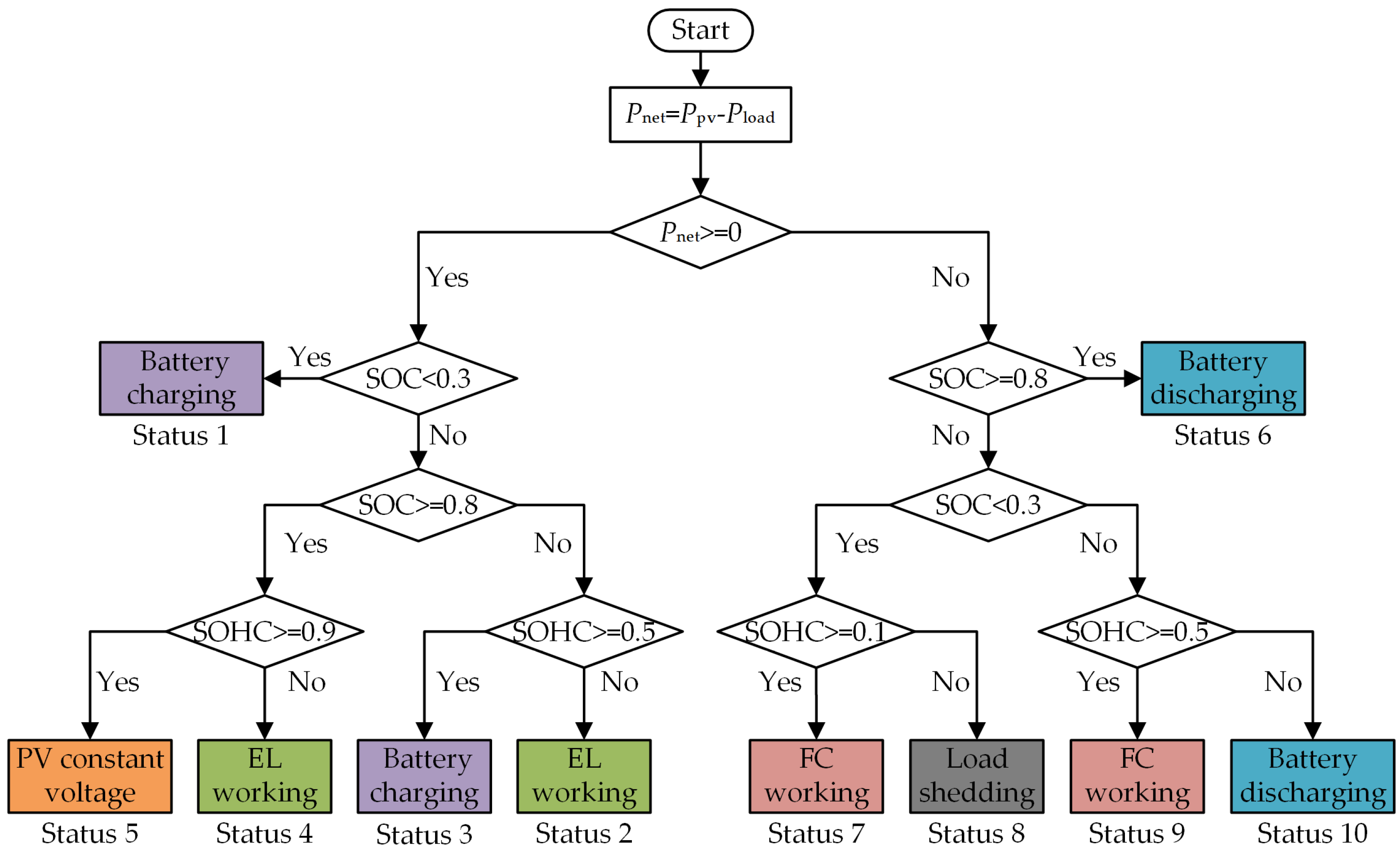
  • An upper-level power management strategy (PMS) is developed to sustain source–load balance while managing the SOC of BESS and the state of hydrogen charge (SOHC) of a hydrogen storage tank (HST). The proposed PMS classifies microgrid operation into 10 distinct statuses according to source–load imbalances along with deviations of SOC and SOHC from their respective boundaries, and dispatches multiple components to balance source and load and prevent the HESS from excessive charge or discharge;
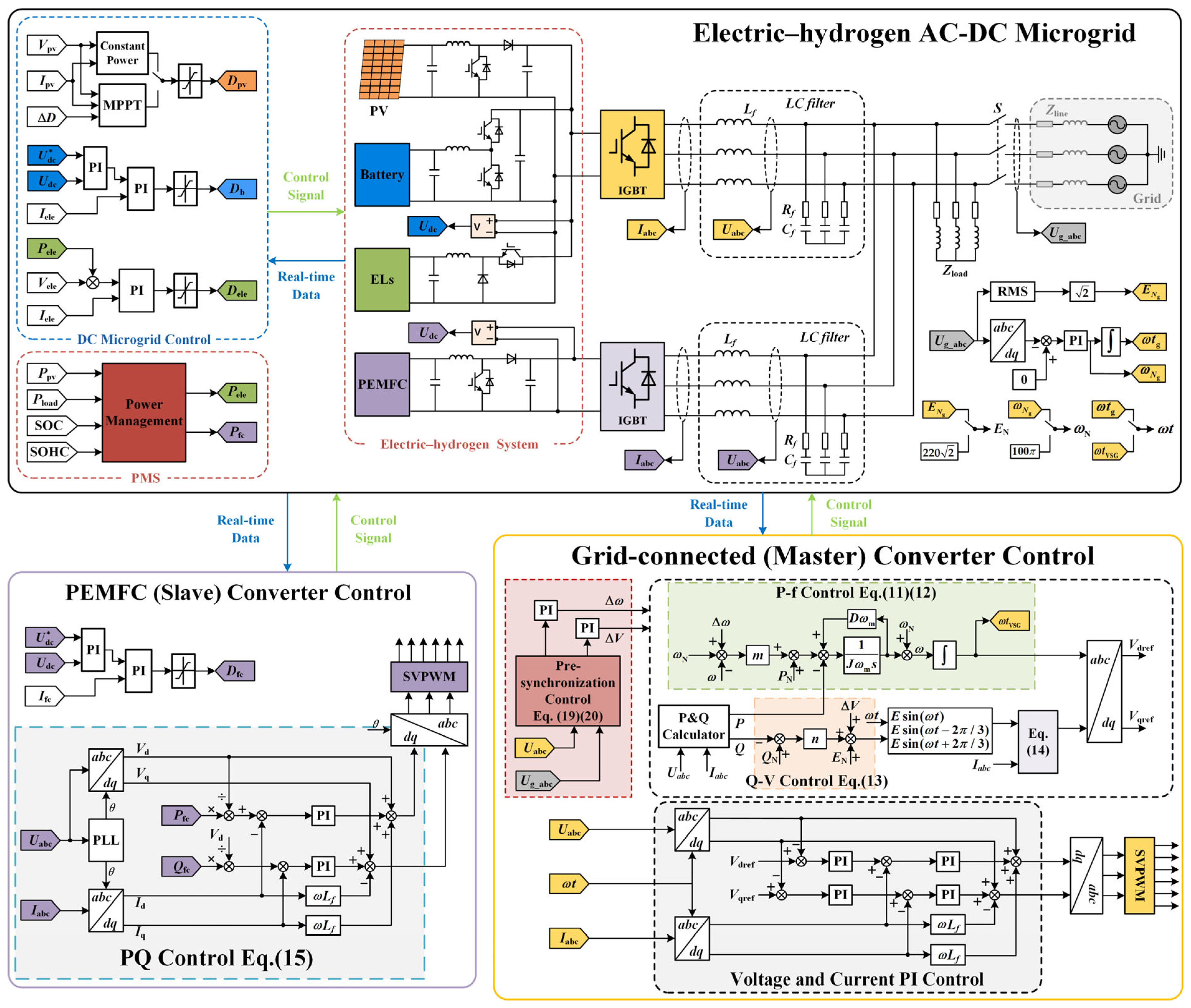
  • A lower-level master–slave control method is developed for the AC-DC hybrid microgrid. The master converter is regulated by virtual synchronous generator (VSG) control, which regulates the dynamic characteristics of the microgrid by modelling the behaviour of a synchronous generator. It is used to stabilise voltage and frequency in the off-grid mode and operate synchronously with the upstream grid in the on-grid mode. The slave converter is regulated by active and reactive power (PQ) control, continuously following the voltage and frequency of the master converter;
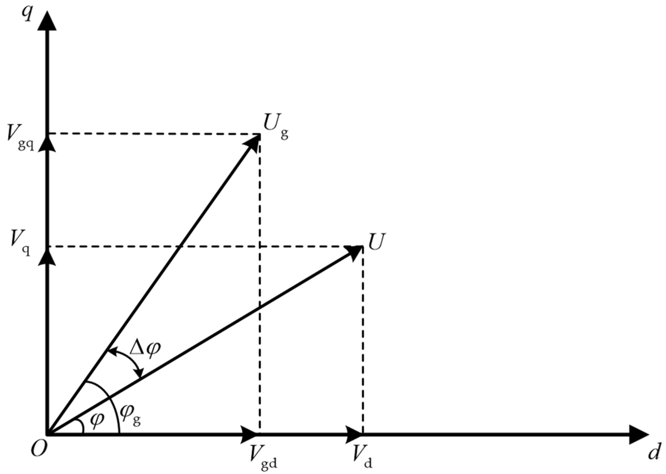
  • A pre-synchronisation control strategy is proposed for a smooth transition from the off-grid to on-grid mode by tracking voltage signals on the two sides of the point of common coupling (PCC). Pre-synchronisation control is generally employed to match voltage amplitude, frequency, and phase of generators with those of the grid in order to avoid voltage fluctuations, current shocks, and other disturbances during connection. The pre-synchronisation strategy proposed here eliminates the need of a PLL module, avoiding accuracy issues associated with the traditional PLL-based synchronisation.
This paper is structured as follows: Section 2 presents the modelling of the electric–hydrogen coupling AC-DC microgrid; Section 3 describes the flexible on-grid and off-grid control method proposed for the microgrid; Section 4 discusses the simulation results of microgrid control under different operating modes and scenarios; and conclusions and recommendations for future work are presented in Section 5.

2. Electric–Hydrogen Coupling AC-DC Microgrid

2.1. Electric–Hydrogen Coupling AC-DC Microgrid Scheme

The electric–hydrogen coupling AC-DC microgrid simulated in this work is mainly comprised of PV panels, BESS, DC loads, and alkaline and PEM ELs on the DC side and FCs and AC loads on the AC side, as illustrated in Figure 1. PV panels are linked to the DC bus through a boost DC-DC converter. The BESS which can adjust power outputs in both directions is connected to the DC bus through a bidirectional DC-DC converter. ELs absorb electricity from the DC bus via buck DC-DC converters. FCs put electricity onto the AC bus via a two-stage converter, which consists of a DC-DC converter cascaded with a DC-AC inverter. The electricity transfer between the DC and AC buses is performed by a bidirectional DC/AC converter. In addition, the microgrid is linked to the upstream grid through a bidirectional DC/AC converter, which is controlled as a voltage source to enable on- and off-grid operation as well as the seamless switching between the two modes.
The BESS, together with ELs, FCs, and an HST, form an electric–hydrogen HESS. In the main, the exceedance of PV generation over AC and DC loads is stored by the BESS and/or converted into hydrogen via Els, depending on the SOC of BESS and the SOHC of HST. When PV power outputs are insufficient, the remaining microgrid loads are supplied by either or both BESS and FCs, depending on the levels of SOC and SOHC.

2.2. Electric–Hydrogen Coupling Microgrid Modelling

2.2.1. PV Generator Model
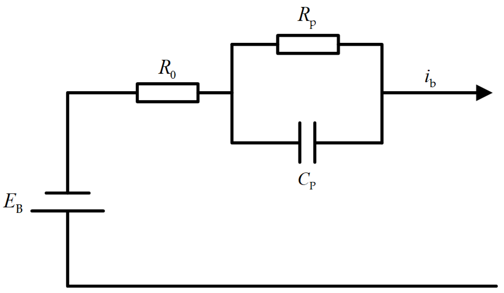
PV power generation techniques have been intensively studied and widely applied around the world. In the electric–hydrogen coupling microgrid modelled in this work, the I-V characteristic curve of PV power generation is formulated as follows [25]:
I d = I 0 exp V d V T 1 V T = k T q × n × N cell
where I d , V d , I 0 , and n represent the output current (A), output voltage (V), saturation current (A), and ideality factor of the PV diode, respectively; k and q are the Boltzmann constant and electronic charge, respectively; T is the cell temperature (°C); and N cell is the number of cells connected in series within a module.

2.2.2. BESS Model

The BESS is modelled here by the Thevenin equivalent circuit [26], as shown in Figure 2 where E B and R 0 denote the DC voltage source (V) and its internal resistance (Ω), respectively, and R p and C p represent the polarisation resistor (Ω) and capacitor (F), respectively.
SOC level is an essential indicator of the energy available in the BESS. Given the initial SOC level SOC ( t 0 ) of BESS at time t 0 , the SOC level SOC ( t ) at time t can be estimated from charging and/or discharging currents i b (A) over the period of t 0 t based on the ampere-hour integration algorithm. This is formulated as follows:
SOC ( t ) = SOC ( t 0 ) 1 Q 0 t 0 t i b ( t ) d t
where Q 0 denotes the rated energy storage capacity (Ah) of BESS.

2.2.3. Hydrogen Energy System Model

The hydrogen energy system modelled here primarily comprises ELs, HST, and FCs, which are described as follows.
  • PEM FC model
The output voltage V fc (V) [27] and hydrogen consumption rate n fc (mol/s) [28] of PEM FCs can be formulated as follows:
V fc = E Nernst U act U ohm U conc
n fc = N fc i fc 2 F
where E Nernst represents the Nernst potential (V), and U act , U ohm , and U conc denote the activation, ohmic, and concentration overvoltage (V), respectively; N fc is the number of individual cells which are assumed to have the same output current i fc (A); and F is the Faraday’s constant.
2.
PEM and ALK EL models
PEM and ALK ELs are jointly implemented within the microgrid to leverage complementary technical characteristics and the adaptability of the two technologies, enhancing the overall performance of EL systems. The output voltage V c e l l (V) of a single cell within an EL can be formulated by the following [29,30]:
V cell = E 0 + V act + V ohm
where E 0 denotes the open circuit voltage (V), which is similar to the output voltage of FCs; and V act and V ohm denote the activation and ohmic overvoltage (V), respectively.
The hydrogen production rate (mol/s) n ele and Faraday efficiency η F are also key parameters of an EL [11], which can be formulated by (6) and (7) as follows:
n ele = η F N ele 2 F i ele
η F = ( i ele / A ) 2 k 1 + ( i ele / A ) 2 k 2
where N ele represents the total number of series-connected cells within an EL which are assumed to have the same current i ele (A); k 1 and k 2 are the Faraday efficiency coefficients; and A represents the surface area (m2) of the EL electrode.
3.
HST Model
The mole of hydrogen W net (mol) stored in HST can be updated by (8) based on n fc and n ele over the period from t 1 to t 2 [31].
W net = t 1 t 2 n ele n fc d t
The amount of hydrogen stored in HST is usually indicated by the SOHC, which can be determined as follows:
SOHC = β hst β max
where β max denotes the maximum pressure (Pa) that the HST can withstand, and β hst is the present pressure (Pa) of the HST which can be calculated by the following:
β hst = T hst R V hst ( W net + W 0 )
where R is the gas constant; T hst and V hst represent the temperature (K) and volume (m3) of HST, respectively; and W 0 is the initial mole of hydrogen (mol) in HST.

3. Control of Electric–Hydrogen Coupling AC-DC Microgrid

3.1. DC Microgrid Converter Control

The microgrid modelled in this work is primarily composed of PV panels, BESS, and ELs on the DC side. The maximum power point tracking (MPPT) control algorithm based on the Perturb and Observe (P&O) method [32] is applied to regulate the boost DC-DC converter of PV panels. When the access to the microgrid is constrained, PV panels will operate under a constant voltage mode, which will be detailed in Section 3.2.
Based on the net microgrid load observed on the DC bus, the BESS exchanges electricity with the microgrid through its bidirectional DC-DC converter, which relies on dual closed-loop PI control for both voltage and current [33]. Surplus PV generation can also be consumed by ELs via a buck DC-DC converter, which is regulated by a single current loop control method in combination with the reference current (i.e., the ratio of EL load to cell voltage). When PV outputs are insufficient, FCs can inject electricity into the AC bus of the microgrid through a two-stage converter, in which the DC/DC converter is regulated by constant voltage control, and the control method of the DC/AC converter will be introduced in Section 3.3.2.

3.2. Power Management Strategy

The operation of BESS, Els, and FCs within the microgrid is coordinated by a particularly designed PMS, which specifies 10 operating statuses based on the SOC, SOHC, and source–load imbalance. A SOC range from 0.3 to 0.8 is adopted here to keep the BESS from deep discharge and overcharging for an extended lifespan and high-efficiency operation. Since the HST allows for a full utilisation of storage capacity without significantly affecting performance and lifetime, a SOHC range between 0.1 and 0.9 is chosen here, allowing the hydrogen energy system to operate over a wider range of SOHC.
A flowchart describing the PMS of the electric–hydrogen coupling AC-DC microgrid is illustrated in Figure 3, where P net (W) is the rise of the available PV power output P pv (W) above the total microgrid load P load (W).
In the case of P net 0 or P net < 0 , five operating statuses are specified in the PMS, respectively. For P net 0 where there is surplus PV generation:
Status 1 ( SOC < 0.3 ): The BESS is in charging mode to increase its insufficient SOC, while ELs and FCs do not exchange power with microgrid.
Status 2 ( 0.3 SOC < 0.8 and SOHC < 0.5 ): ELs absorb electricity to increase its SOHC, FCs do not discharge, and the BESS stabilises the DC bus voltage.
Status 3 ( 0.3 SOC < 0.8 and SOHC 0.5 ): Same coordination as Status 1.
Status 4 ( SOC 0.8 and SOHC < 0.9 ): Same coordination as Status 2 given the BESS reaching or exceeding the upper SOC limit.
Status 5 ( SOC 0.8 and SOHC 0.9 ): Given SOC and SOHC reaching their respective upper limits, the microgrid enters in a saturated state which cannot accept any surplus PV generation. In this status, ELs and FCs are inactive and the BESS stabilises the DC bus voltage. A constant power control strategy is applied to the boost the DC-DC converter of PV panels to match its output voltage with the DC bus voltage.
For P net < 0 where there is a shortage of power supply:
Status 6 ( SOC 0.8 ): The BESS is in discharging mode to reduce its excessive SOC, while ELs and FCs do not exchange electricity with microgrid.
Status 7 ( SOC < 0.3 and SOHC 0.1 ): FCs consume hydrogen to export electricity to microgrid, ELs do not import, and the BESS stabilises the DC bus voltage.
Status 8 ( SOC < 0.3 and SOHC < 0.1 ): Given SOC and SOHC falling below their respective lower limits, ELs and FCs are inactive and the BESS stabilises the DC bus voltage. Controllable loads will be reduced to balance the microgrid.
Status 9 ( 0.3 SOC < 0.8 and SOHC 0.5 ): Same coordination as Status 7.
Status 10 ( 0.3 SOC < 0.8 and SOHC < 0.5 ): Same coordination as Status 6.
To facilitate the PMS implementation, real-time data of loads, available PV outputs, the SOC of BESS, and the SOHC of HST will be collected and fed into a power management unit. Based on the monitored data, the PMS determines the appropriate operating status and generates corresponding set-points for the BESS, Els, and FCs, which are then assigned to their converters to realise coordinated and stable operation. Compared to an optimisation-based EMS which dynamically optimises microgrid coordination based on short-term predictions of renewable generation and demands, the proposed PMS has the advantages of easy implementation and fast computation. It is noted that suitable boundaries of SOC and SOHC adopted by PMS are generally optimised in conjunction with capacity configuration at the system planning stage, in order to, e.g., maximise net profits of systems or minimise levelised costs of hydrogen production based on historic data or related stochastic data. This will ensure overall system performance during the entire lifespan, though the lack of dynamic parameter adjustment disables PMS from adapting to future changes in sources and loads, which might cause certain losses in short-term renewable integration or related revenue.

3.3. DC/AC Converter Control

The control block diagram of the electric–hydrogen coupling AC-DC microgrid is illustrated in Figure 4, which primarily includes the control of master and slave converters and the pre-synchronisation control for off-grid/on-grid transition. The master converter is responsible for linking the DC bus to the AC bus, while the slave converter is used to connect FCs to the AC bus. When the microgrid is in the on-grid mode, both master and slave converters operate with grid frequencies as the reference. When the microgrid enters the off-grid mode, the constant voltage and frequency required are provided by the master converter, while the slave converter operates with microgrid frequencies as the reference. The specific algorithms are outlined as follows.

3.3.1. Master DC/AC Converter Control

The grid-forming DC/AC converter is used as the master converter which adopts the VSG control strategy. When the microgrid is in the off-grid mode, the references of frequency and voltage are 50 Hz and 220 2 V, respectively. When the microgrid is in the on-grid mode, the references of frequency and voltage are based on grid-side measurements. The VSG control strategy used in this work includes active power–frequency (P-f) control, reactive power–voltage (Q-V) control, and virtual impedance control.
  • Active power–frequency control [34]
The dominant feature of VSG control is to simulate the rotational inertia of synchronous generator rotors, thereby providing virtual inertia to grids. Analogous to the mathematical model of synchronous generators, the P-f relationship is formulated as follows:
J d ω d t = P m ω m P ω m D ( ω ω N )
where J is the virtual moment of inertia (kg · m2); D is the damping coefficient (kg·m2/s); ω , ω m , and ω N denote electrical, mechanical, and grid synchronous angular velocities (rad/s), respectively; and P m and P are the mechanical and electromagnetic power (W), respectively.
Equation (11) indicates that virtual inertia and damping coefficients exist in VSG control, which mitigate instant changes in microgrid frequencies caused by load variations in active power, ensuring the frequency stability of the microgrid. In addition, a P-f droop link is added into the control strategy to simulate primary frequency regulation characteristics of synchronous generators. This is formulated by the following:
P m = P N + m ( ω ω N )
where P N is the reference of active power (W) and m is the P-f droop adjustment coefficient (kg·m2/s2). The combination of (11) and (12) forms the P-f control block, as shown in Figure 4.
2.
Reactive power–voltage control [34]
According to the reactive power of loads, the internal potential of VSG is adjusted in real time by the Q-V control link, which is formulated as follows:
E = E N + n ( Q Q N )
where E and E N are actual and reference values of internal potential (V) of VSG, respectively; n is the adjustment coefficient (V/var) of the Q-V droop; and Q and Q N are actual and reference values of reactive power output (Var), respectively. Equation (13) forms the Q-V control block, as shown in Figure 4.
3.
Virtual impedance control [35]
In order to model electrical characteristics of synchronous generator stators, the electromagnetic equation is introduced to reflect the relationship between the internal potential and output voltage of VSG, as formulated by (14). This forms the virtual impedance control block, as shown in Figure 4.
e abc = R v s i abc + L v s d i abc d t + u abc
where e abc , u abc , and i abc represent the internal potential (V), output voltage (V), and current (A) of VSG, respectively; and R v s and L v s denote virtual synchronous resistance (Ω) and reactance (H), respectively.
The overall control block of the master DC/AC converter is shown in Figure 4. The voltage and current signals of the master converter are first collected to calculate active and reactive power outputs of VSG. Then, the reference voltage is obtained through (11)–(14). Finally, the dual closed-loop control is used for voltage and current to achieve the stable control of the system.

3.3.2. Slave DC/AC Converter Control

As a slave converter, the DC/AC converter of FCs adopts the PQ control. When the microgrid is in the off-grid mode, reference values of frequency and voltage of the slave converter are based on the frequency and voltage of the master converter. When the microgrid is in the on-grid mode, references of the frequency and voltage of the slave converter are based on the frequency and voltage of the upstream grid, which actually equal the frequency and voltage of the master converter. Therefore, the slave converter always follows the master converter in terms of frequency and voltage, regardless of the operating mode of microgrid.
In actual operation, the slave converter always runs in the ‘grid-connected’ mode by adjusting active and reactive currents to track references of active and reactive power, as follows:
P ref = V d I d - ref Q ref = V d I q - ref
where P ref and Q ref are references of active power (W) and reactive power (Var) of the slave converter, which are determined by the PMS (see Section 3.2) and the reactive power of loads, respectively. V d is the voltage transformation value (V) at the interface between the master and slave converters. I d - ref and I q - ref are references of active and reactive currents (A) of the slave converter, respectively, which will be fed into the current controller in inner loop. The overall control block of the slave converter is shown in Figure 4.

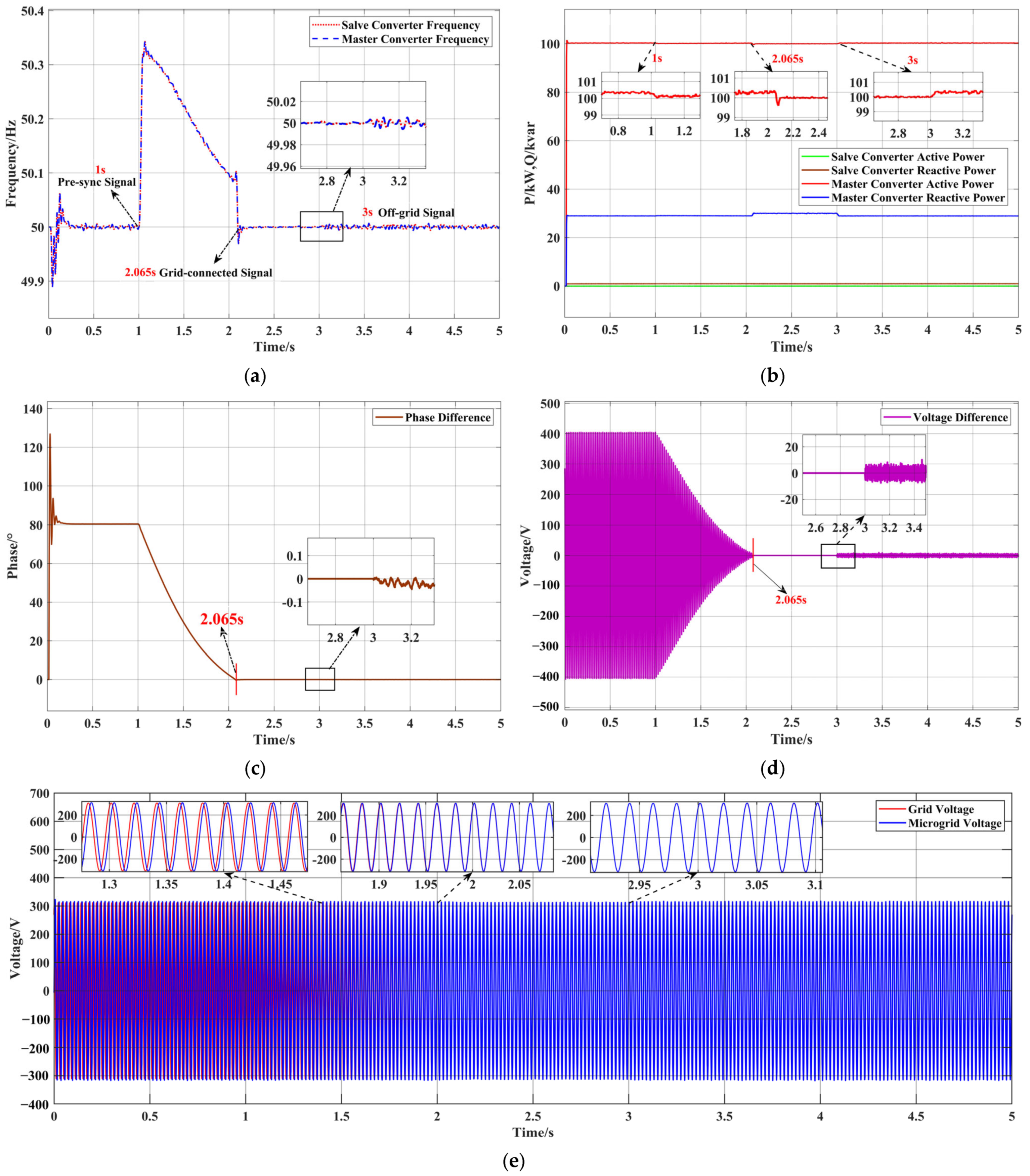
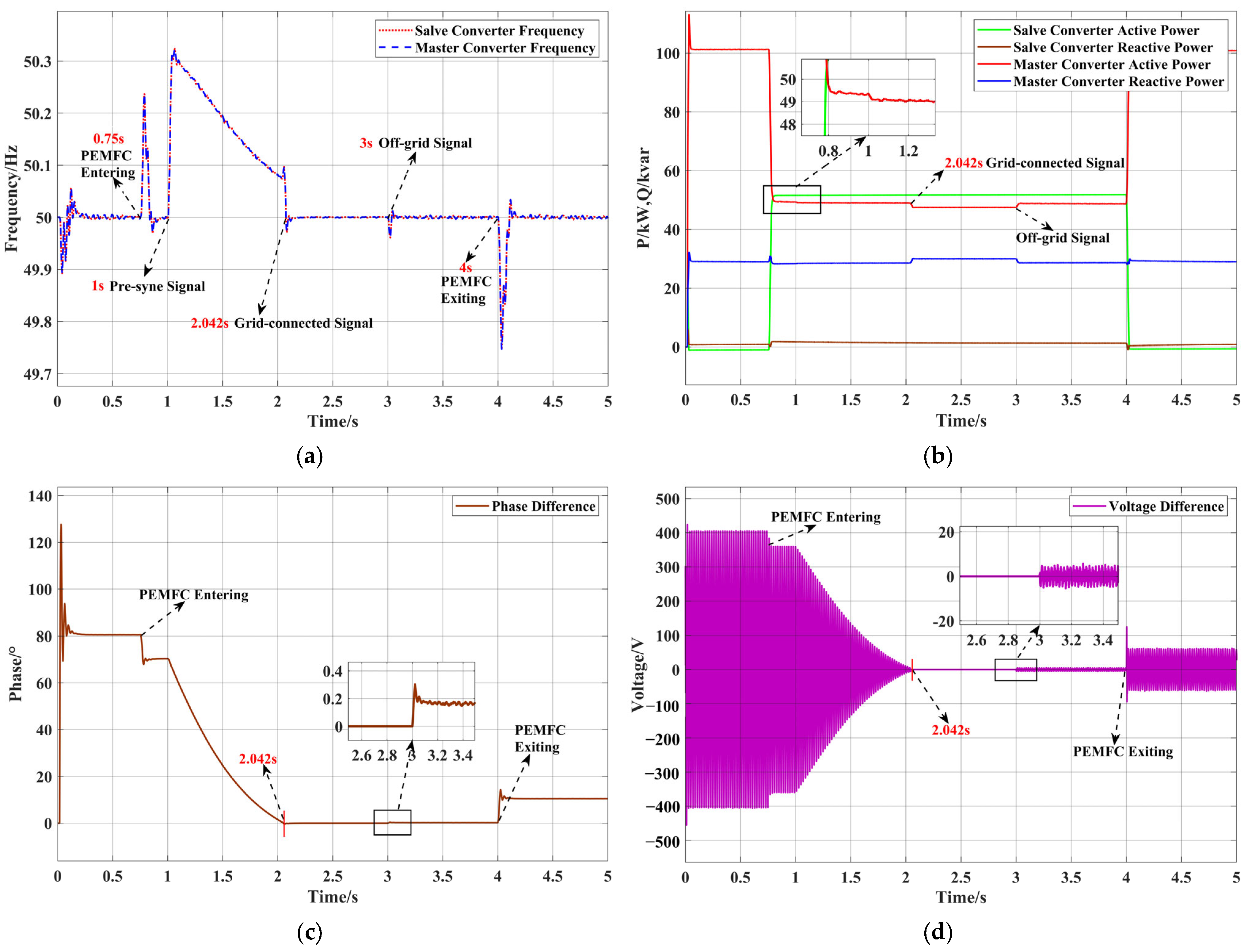
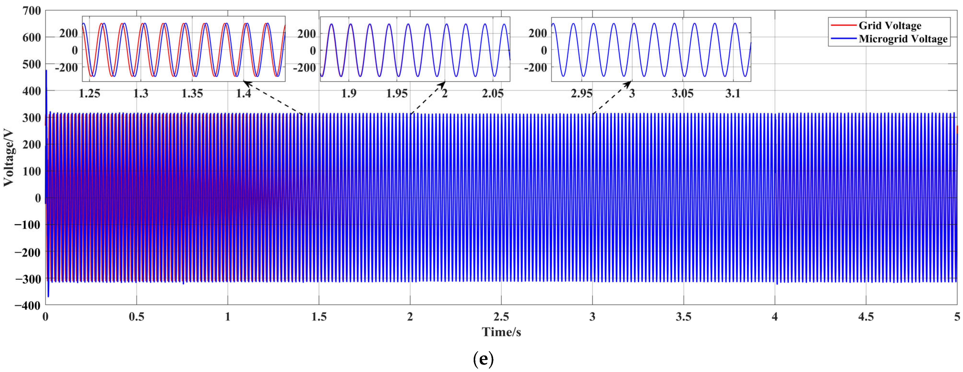
3.3.3. On-Grid/Off-Grid Switching Strategy

The electric–hydrogen AC-DC microgrid modelled in this work can operate in both off- and on-grid modes. In order to ensure the uninterrupted and stable operation of the microgrid, smooth switching between the two modes is particularly important. This section analyses the switching process from the off-grid to the on-grid mode, followed by detailing the pre-synchronisation control that does not rely on PLLs.
  • Analysis of switching from off-grid to on-grid
When the master converter operates in the off-grid mode, the two sides of the PCC might be different in frequency, resulting in real-time changes in phase difference. At the same time, there might also exist differences in voltage amplitude between the two sides. Without an appropriate voltage adjustment prior to grid connection, a large current shock and voltage fluctuations would occur. Taking phase A as an example, the grid-side voltage and master converter voltage in the off-grid mode are assumed to be u gA and u A with amplitudes of U 1 and U 2 , angular frequencies of ω 0 and ω , and initial phases of φ 1 and φ 2 , respectively, formulated as follows:
u gA = U 1 sin ( ω 0 t + φ 1 ) u A = U 2 sin ( ω t + φ 2 )
Since the amplitude U 0 of the VSG output voltage in the off-grid mode shall be almost equal to the grid voltage amplitude U 1 (i.e., U 1 U 2 = U 0 ) prior to grid connection, the voltage difference u between the two sides of the PCC can be formulated as follows:
Δ u = u gA u A = U 1 sin ( ω 0 t + φ 1 ) U 2 sin ( ω t + φ 2 )   2 U 0 sin ω 0 ω 2 t + φ 1 φ 2 2 cos ω 0 + ω 2 t + φ 1 + φ 2 2
which indicates that without a pre-synchronisation process, u can reach as large as 2 U 0 and the impulse current will be very high, leading to grid connection failure and system collapse. Therefore, pre-synchronisation must be implemented to realise seamless and stable switching from the off-grid to the on-grid mode.
2.
Pre-synchronisation control for grid connection
An appropriate pre-synchronisation control strategy is essential for the smooth switching of microgrids. Once the grid-connection signal is issued, the pre-synchronisation control adjusts the master converter voltage to have the same frequency and phase as the grid-side voltage prior to grid connection. The pre-synchronisation control strategy proposed in this work employs two PI controllers only and eliminates the need of PLLs in traditional pre-synchronisation strategies. This improves the pre-synchronisation speed and avoids the low precision problem caused by PLLs.
The vector diagrams of VSG voltage and grid-side voltage in two-phase rotating coordinate are shown in Figure 5, where V d and V q (or V gd and V gq ) denote the components (V) of VSG voltage (or grid-side voltage) along the d-axis and q-axis, respectively.
In the pre-synchronisation process, when the phase difference Δ φ (°) between the VSG output voltage phase φ g (°) and grid voltage phase φ (°) is sufficiently small, i.e., equal to or smaller than 3 ° in this work, the following relationship exists:
sin Δ φ Δ φ for   Δ φ 3 °
Therefore, sin Δ φ can be used to indicate the completion of phase synchronisation. According to the vector relationship in Figure 5, sin Δ φ can be calculated by the following:
sin Δ φ = sin φ g φ = V gq V d V gd V q V d 2 + V q 2 × V gd 2 + V gq 2
which can be minimised in magnitude by adjusting the voltage phase of VSG output until the voltage phase synchronisation between the two sides of the PCC is achieved.
The voltage amplitude can be adjusted according to the voltage amplitude difference between the two sides of PCC, which is defined as follows:
Δ U = U g U 0
Then, Equations (19) and (20) are substituted into PI controllers to obtain frequency disturbances Δ ω and amplitude disturbances Δ V , which will be brought into P-f and Q-V control, respectively. This facilitates the voltage synchronisation between the two sides of the PCC. The pre-synchronisation control block is shown in Figure 4.
3.
Switching from on-grid to off-grid
When the microgrid operates in the off-grid mode, the master converter using the VSG control can provide voltage and frequency support to the microgrid, which is equivalent to an independent voltage source. Therefore, there is no obvious transient process during the switching from the on-grid to the off-grid mode, which will not be detailed here for brevity.

4. Results and Discussions

This section evaluates the effectiveness of the proposed control method in ensuring the stability of the electric–hydrogen coupling microgrid (see Figure 1) in different operating modes. In addition, two distinct scenarios are simulated in the off-grid or on-grid mode to validate the effectiveness of the proposed PMS. The modelling of the electric–hydrogen microgrid along with the proposed control method is accomplished in Matlab/Simulink R2024a. (For further details of simulation modules, the reader is referred to Supplementary Materials). Technical parameters of the microgrid and related components are tabulated in Table 1 and Table 2, respectively.

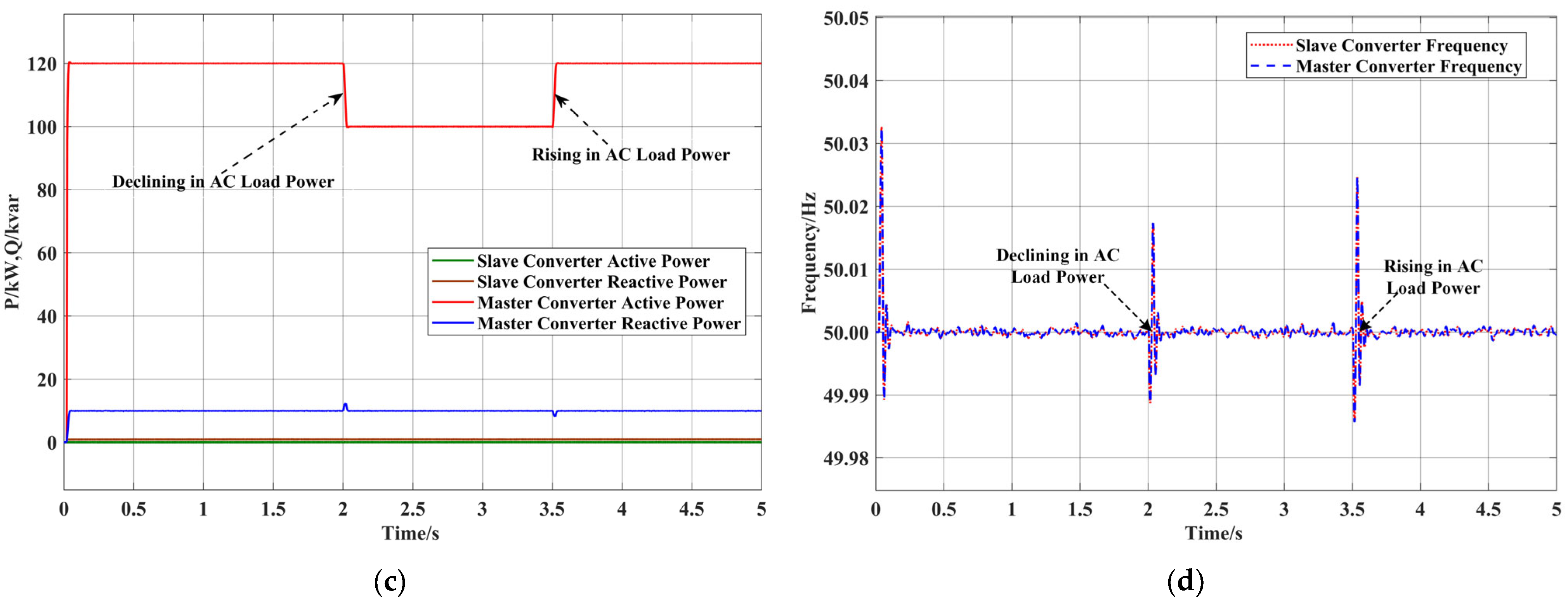
4.1. Off-Grid Operation
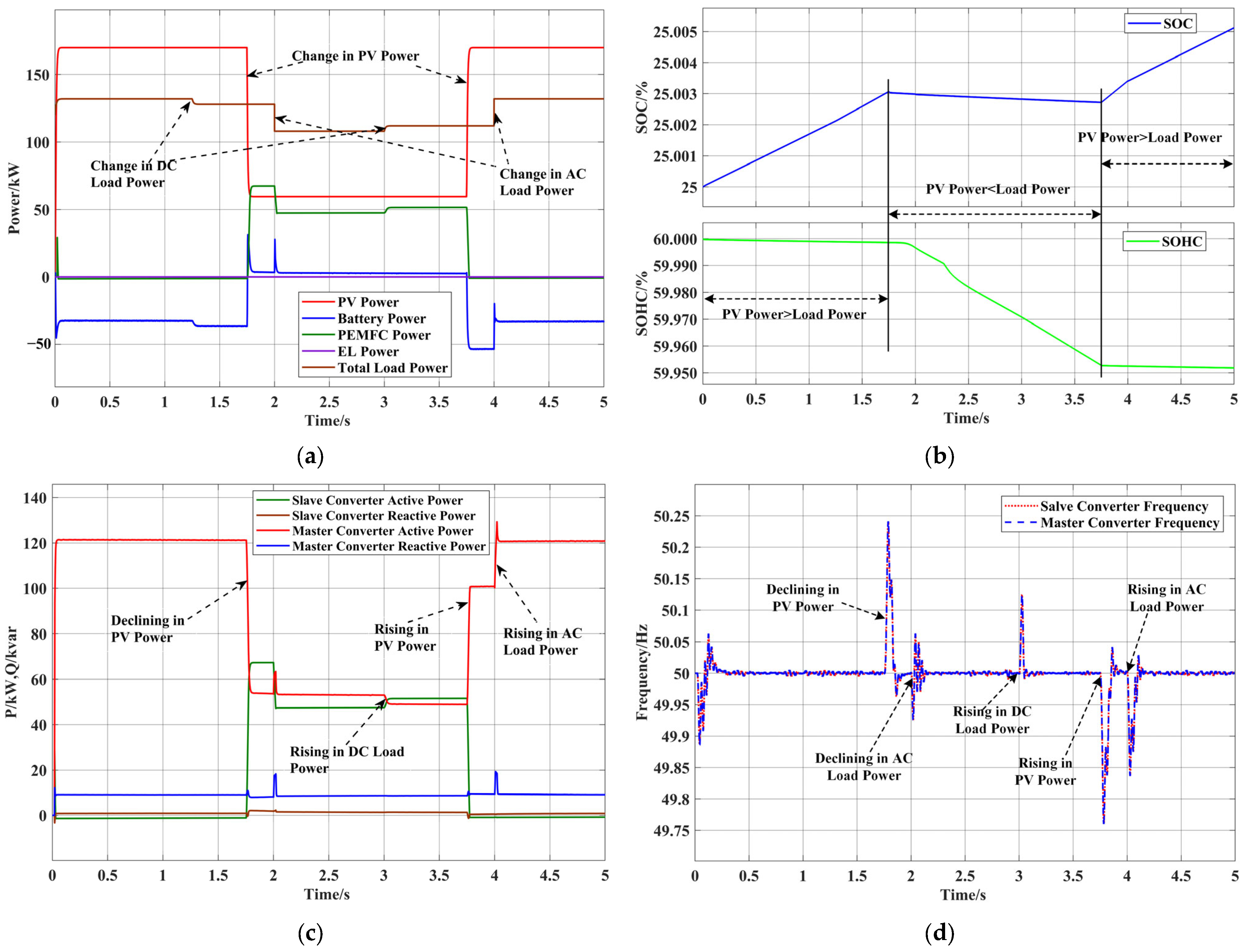
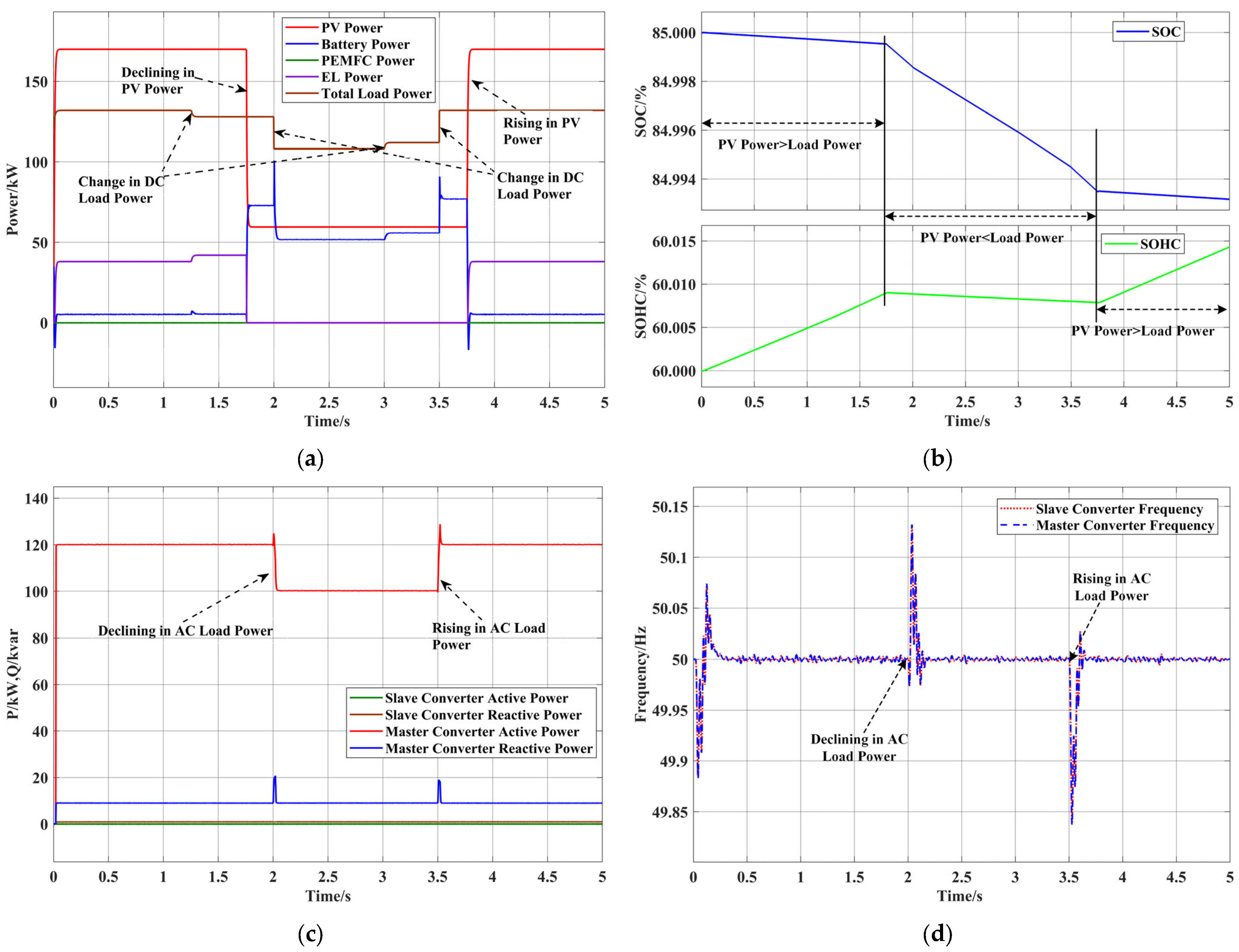
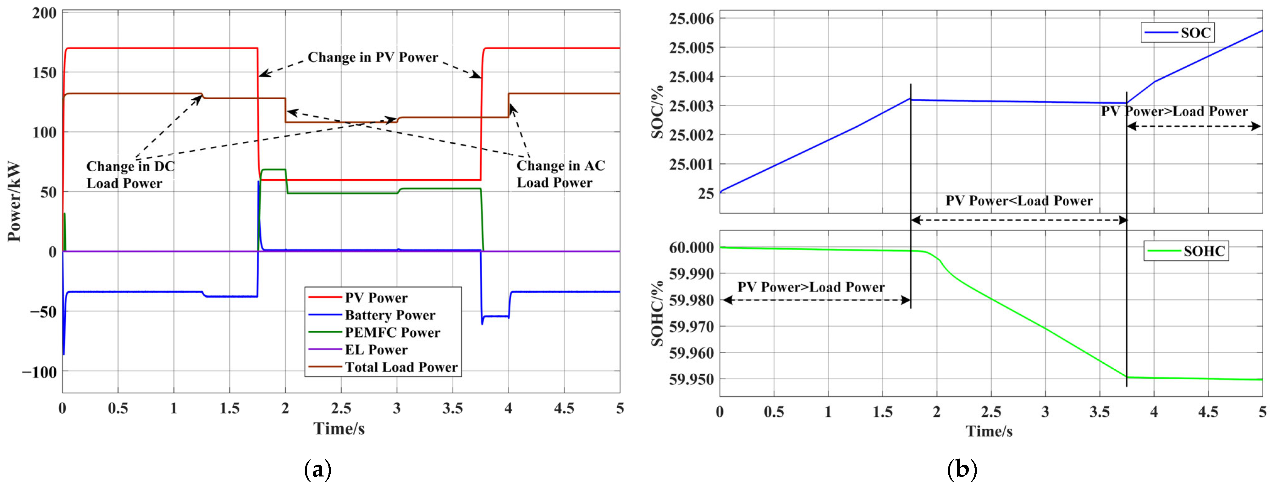
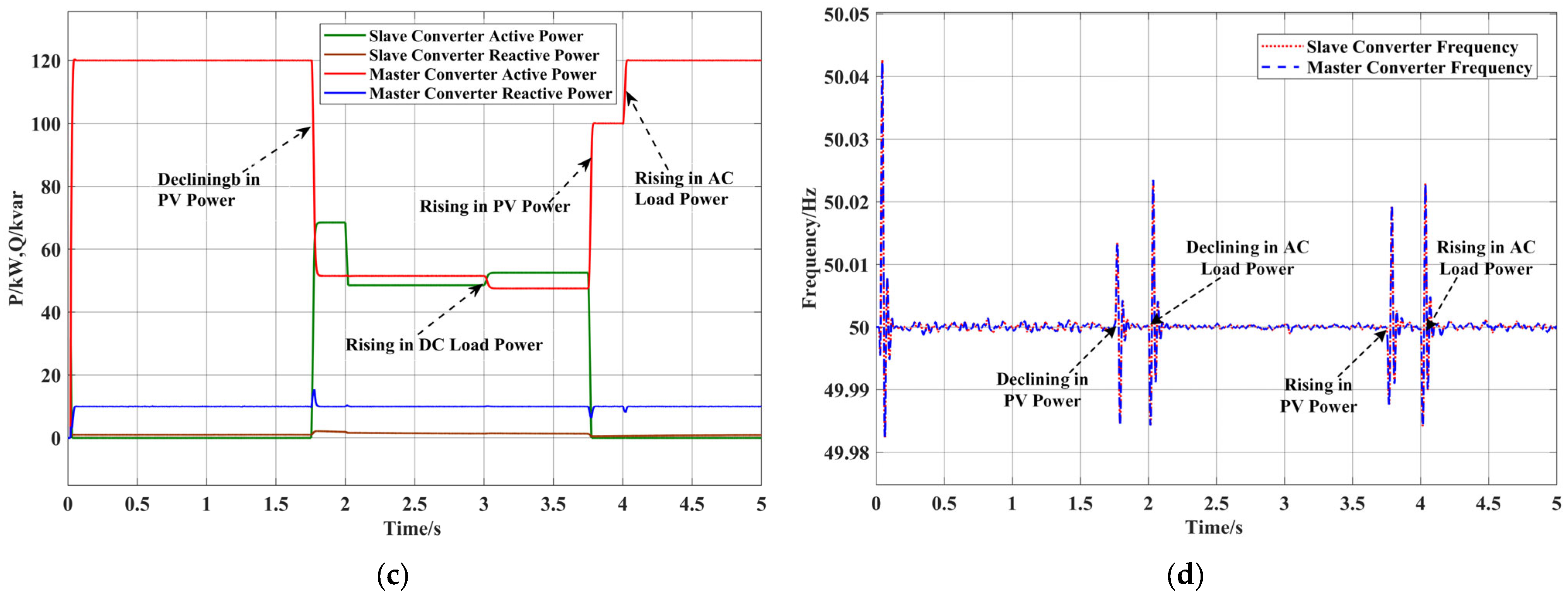
In the off-grid mode, the master converter of the microgrid maintains a stable voltage and frequency using the VSG control strategy. Upon the startup of FCs, their slave converter follows the voltage and frequency of the master converter and supplies electricity to the microgrid under PQ control.

4.1.1. Scenario I

In Scenario I, with initial conditions of SOC = 25%, SOHC = 60%, and P net > 0 , microgrid dynamics under PV output and load variations are shown in Figure 6. The operation process can be divided into three stages:
Stage I (0–1.75 s): PV output is 170 kW, AC load is 120 kW in active power, and DC load starts at 12 kW and decreases to 8 kW at 1.25 s, resulting in P net > 0 .
Stage II (1.75–3.75 s): PV output decreases from 170 kW to 59.5 kW. AC load drops from 120 kW to 100 kW at 2 s, while DC load increases from 8 kW to 12 kW at 3 s.
Stage III (3.75–5 s): PV output rebounds from 59.5 kW to 170 kW, and AC load rises from 100 kW to 120 kW at 4 s.
During the entire process, the reactive power of the AC load remains at 10 kVar.
Figure 6a illustrates power variations of PV panels, BESS, FCs, Els, and total loads at different stages. In Stage I, the microgrid operates in Status 1 of PMS, with excess electricity being absorbed by BESS. In Stage II, PV power outputs are insufficient to meet total loads, prompting the microgrid to transit from Status 1 to Status 7, in which FCs begin to consume hydrogen for electricity supply. In Stage III, the microgrid returns to the operating state of Stage I. The resulting SOC and SOHC waveforms throughout each stage are shown in Figure 6b, respectively.
Power variations of master and slave converters are shown in Figure 6c. When FCs begin exporting to the microgrid, the slave converter is activated to operate. In Stage II, with the DC load increasing at 3 s, the PV power output is used to maintain the power balance on the DC side, resulting in a decrease in the main converter’s power output. With the continuous growth of the DC load (or total microgrid load), FCs compensate for part of the deficit in electricity by exporting electricity through the slave converter. Figure 6d shows frequency fluctuations during microgrid operation. Despite variations in PV power outputs and microgrid loads, frequencies are shown to fluctuate within a reasonable range and ultimately stabilise at 50 Hz.

4.1.2. Scenario II

In Scenario II, with initial conditions of SOC = 85%, SOHC = 60%, and P net > 0 , microgrid dynamics under PV output and load variations are illustrated in Figure 7. In this scenario, the AC load increases from 100 kW to 120 kW at 3.5 s, while the other source and load variations remain the same as those in Scenario I.
Figure 7a depicts power variations of PV panels, BESS, FCs, Els, and total loads. In Stage I, the microgrid operates in Status 4 of PMS where excess electricity is used to drive Els, producing and storing hydrogen in HST. In Stage II, when the PV output is insufficient to meet the total microgrid load, the microgrid transits from Status 4 to Status 6, in which the BESS compensates for the shortage of electricity supply. In Stage III, the operational state returns to that of Status I. The waveforms of the resulting SOC and SOHC are shown in Figure 7b, respectively.
Figure 7c illustrates power variations of the main and slave converters. Since FCs do not supply electricity to the microgrid, the slave converter remains inactive in this scenario. The reactive power of the main converter fluctuates with its active power due to the coupling effect between active and reactive power. Figure 7d shows that the microgrid frequency is controlled within a reasonable range under source and load variations and ultimately stabilises at 50 Hz.
The test results above demonstrate that the electric–hydrogen coupling microgrid can operate stably in the off-grid mode under the proposed control method. Specifically, the VSG control applied to the master converter effectively supports the frequency stability of the islanded microgrid, ensuring reliable frequency regulation and stable off-grid operation.

4.2. On-Grid Operation

In the on-grid mode, the microgrid is synchronised with its upstream grid via the master converter by using VSG control. References of voltage and frequency are obtained by sampling grid-side voltage signals. Then, the slave converter follows the voltage and frequency of the main converter, facilitating coordination between the microgrid and upstream grid and maintaining stable on-grid operation.

4.2.1. Scenario III

Figure 8 shows microgrid dynamics in Scenario III, which has the same available PV power outputs, load changes, and initial conditions as Scenario I. The power waveform of each component, resulting SOC and SOHC waveforms, and power and frequency waveforms of the master and slave converters are presented in Figure 8a–d, respectively. Figure 8a,b show that, compared to the off-grid mode in Scenario I, the connection to the upstream grid significantly mitigates DC-side power fluctuations and output fluctuations of the master and slave converters under AC load variations. Furthermore, when PV outputs or loads fluctuate, microgrid frequency fluctuations are considerably reduced, as shown in Figure 8d. This highlights the effect of grid connection on the frequency stability of the microgrid.

4.2.2. Scenario IV

Figure 9 illustrates microgrid dynamics in Scenario IV, which has the same available PV outputs and loads as well as the same initial conditions as Scenario II, so as to compare microgrid operation between on- and off-grid modes. The power waveform of each component, resulting SOC and SOHC waveforms, and power and frequency waveforms of the master and slave converters are shown in Figure 9a–d, respectively. Figure 9a,b illustrate that, compared to the off-grid mode in Scenario II, the connection to the upstream grid almost eliminates DC-side power fluctuations and output fluctuations of the master and slave converters when AC loads fluctuate. Furthermore, microgrid frequency fluctuations induced by changes in PV outputs and loads are significantly reduced under on-grid operation, as shown in Figure 9d. This demonstrates that the integration with upstream microgrid effectively mitigates frequency instability.
The test results above demonstrate that the electric–hydrogen coupling microgrid can operate stably in the on-grid mode under the proposed control method. Furthermore, in the on-grid mode, the connection of the microgrid to the upstream grid significantly reduces frequency fluctuations when the microgrid experiences variations in PV outputs and loads.

4.3. Off-Grid/On-Grid Switching

The capability of smooth switching between on- and off-grid modes is crucial to ensure stable microgrid operation at times of fault occurrence or clearance in upstream grid. Two particular scenarios are designed here to verify the effectiveness of the proposed control method in mode switching: Scenario V where the master converter operates independently and Scenario VI where master and slave converters operate in tandem. The initial phase of phase A of the main converter or upstream grid is set to 0° or 60°, respectively. The phase difference is intentionally set to model synchronisation processes when the microgrid transits from the initial off-grid mode to the on-grid mode, allowing for an assessment on the performance of the control method in ensuring microgrid stability over switching processes.

4.3.1. Scenario V

In Scenario V, with SOC = 60% and SOHC = 60%, available PV outputs are assumed to be 170 kW, which consistently meets total microgrid loads (i.e., constantly at 100 kW and 30 kVar for a 5-s period) while FCs are not in operation. Figure 10a–d show waveforms of frequency and power of the master and slave converters, differences in voltage phase, and amplitude between the two sides of the PCC during switching processes, respectively. At 1 s, a pre-synchronisation signal is assigned to initiate the proposed pre-synchronisation control to adjust the microgrid voltage and frequency, as shown in Figure 10e. When the pre-synchronisation control successfully reduces the differences in the voltage phase and amplitude between the microgrid and upstream grid to fulfil grid-connection requirements at 2.065 s, as shown in Figure 10c,d, the grid-connection switch is closed for the microgrid transition to the on-grid mode. At 3 s, the grid-connection switch is disconnected and the microgrid returns to the off-grid mode. Throughout the entire switching process, frequencies fluctuate within a reasonable range and power fluctuations of converters are minimal, as shown in Figure 10a,b, respectively. These results demonstrate that the proposed control method effectively achieves a smooth transition between on- and off-grid modes in this scenario.

4.3.2. Scenario VI

In Scenario VI, with initial conditions of SOC = 25% and SOHC = 60%, available PV outputs are assumed to drop from 170 kW to 59.5 kW at 0.75 s and then increase back to 170 kW at 4 s. Since available PV outputs cannot meet AC loads of 100 kW and 30 kVar (i.e., P net < 0 ) over 0.75–4 s, FCs are required to export through the slave converter in this period. Figure 11a–d show frequency waveforms of master and slave converters and differences in the voltage phase and amplitude between the microgrid and upstream grid during switching processes, respectively. At 0.75 s, FCs begin exporting to the microgrid through the activated slave converter, as shown in Figure 11b. At 1 s, a pre-synchronisation signal is assigned to trigger the pre-synchronisation control to regulate the microgrid voltage and frequency, as shown in Figure 11e. At 2.042 s, the microgrid meets requirements for grid connection, as shown in Figure 11c,d, where differences in the voltage amplitude and phase between the two sides of the PCC are sufficiently small. Then, the grid-connection switch is closed and the microgrid transits to the on-grid mode. At 3 s, the grid-connection switch is disconnected and the microgrid reverts to the off-grid mode. Due to the existence of a filter in the slave converter, there are relatively large differences in the voltage amplitude and phase between the two sides of the PCC when FCs start or stop exporting, as shown in Figure 11c,d. Figure 11a shows that the microgrid frequency remains within a reasonable range throughout switching processes, indicating that the proposed control method realises a smooth transition between on- and off-grid modes in this scenario.
The test results above demonstrate that the proposed control method can effectively synchronise the voltage amplitude and phase of the microgrid with those of its upstream grid and enable smooth switching between on- and off-grid modes, ensuring flexible and reliable microgrid operation. This also means that the threshold of sin Δ φ corresponding to Δ φ 3 ° is an effective indicator for voltage phase synchronisation in this case.

5. Conclusions

This paper has developed an integrated model of a practical electric–hydrogen coupling AC-DC microgrid, which comprised photovoltaic (PV) panels, a battery energy storage system (BESS), electrolysers (ELs), fuel cells (FCs), a hydrogen storage tank (HST), and AC and DC loads. In addition, a flexible on-grid and off-grid control method with a hierarchical structure has been proposed for microgrid regulation. At the upper level, a power management strategy (PMS) has been designed for microgrid coordination based on the state of charge (SoC) of BESS and the state of hydrogen charge (SOHC) of HST. At the lower level, PV panels selected either constant power or maximum power point tracking control, depending on the available access to the microgrid. Furthermore, the BESS regulated the DC bus voltage through constant voltage control, while ELs followed a constant power control strategy. Moreover, a master–slave control strategy has been developed for the DC/AC converters of the BESS and FCs. The master converter linking the microgrid to the upstream grid adopted virtual synchronous generator control, which stabilised the microgrid voltage and frequency under the off-grid mode or synchronised with the upstream grid in the on-grid mode. The slave converter continuously followed the master converter under active and reactive power control. In addition, a pre-synchronisation control strategy which did not rely on phase-locked loops has been proposed to ensure a fast and smooth transition from the off-grid to the on-grid mode. The microgrid model along with the proposed control method has been tested under on-grid, off-grid, and on-grid/off-grid switching modes given different combinations of SOC, SOHC, and source–load imbalances. The simulation results have demonstrated that the proposed control method can effectively ensure the voltage and frequency stability of the microgrid against fluctuations of PV outputs and loads in all the scenarios under tests.
Building on the microgrid model and control method developed here, semi-physical simulation experiments will be conducted using a real-time simulation platform to evaluate model and control performance under complex environments. Furthermore, future work will implement field tests based on the real-world electric–hydrogen coupling microgrid to validate the effectiveness of the proposed control method in practice.

Supplementary Materials

The following supporting information can be downloaded at: https://www.mdpi.com/article/10.3390/en18040985/s1, Figure S1. Simulation modules of PV panels and BESS within microgrid. Figure S2. Simulation modules of EL and HST within microgrid. Figure S3. Simulation modules of PEMFCs and PQ control of slave converter. Figure S4. Simulation modules of VSG control of master converter and pre-synchronisation. Figure S5. Simulation module of the PMS for the electric–hydrogen microgrid.

Author Contributions

Conceptualization, K.S. and Z.C.; methodology, Z.W., H.Z., and F.F.; software, Z.W.; validation, Z.W., H.Z., F.F., and J.Z.; formal analysis, Z.W., H.Z., F.F., and J.Z.; investigation, Z.W., H.Z., F.F., and J.Z.; resources, K.S. and Z.C.; data curation, Z.W. and J.Z.; writing—original draft preparation, Z.W. and F.F.; writing—review and editing, K.S., J.J., C.S., R.X., and J.Z.; visualization, Z.W.; supervision, F.F., K.S., J.J., C.S., and R.X.; project administration, K.S. and Z.C.; funding acquisition, K.S. and Z.C. All authors have read and agreed to the published version of the manuscript.

Funding

We acknowledge the support of the Shenzhen Energy Group Company Ltd. for the Key Technology Research Project of the Integrated Energy Utilization System of Photovoltaic Green Hydrogen.

Data Availability Statement

The original contributions presented in this study are included in the article. Further inquiries can be directed to the corresponding authors.

Conflicts of Interest

Authors Jingran Zhang and Zhengjian Chen were employed by the Shenzhen Energy Group Company Ltd. The authors declare that this study received funding from Shenzhen Energy Group Company Ltd. The funder was not involved in the study design, collection, analysis, interpretation of data, the writing of this article or the decision to submit it for publication. The remaining authors declare that the research was conducted in the absence of any commercial or financial relationships that could be construed as a potential conflict of interest.

References

  1. Østergaard, P.A.; Duic, N.; Kalogirou, S. Sustainable development using integrated energy systems and solar, biomass, wind, and wave technology. Renew. Energy 2024, 235, 121359. [Google Scholar] [CrossRef]
  2. Peng, B.; Li, Y.; Liu, H.; Kang, P.; Bai, Y.; Zhao, J.; Nian, H. Design of Energy Management Strategy for Integrated Energy System Including Multi-Component Electric–Thermal–Hydrogen Energy Storage. Energies 2024, 17, 6184. [Google Scholar] [CrossRef]
  3. Elalfy, D.A.; Gouda, E.; Kotb, M.F.; Bureš, V.; Sedhom, B.E. Comprehensive review of energy storage systems technologies, objectives, challenges, and future trends. Energy Strategy Rev. 2024, 54, 101482. [Google Scholar] [CrossRef]
  4. Ranjan, A.; Bodkhe, S.; Goyal, G.; Belge, A.; Tibude, S. Experimental Study on Heuristics Energy Management Strategy for Hybrid Energy Storage System. Energies 2024, 17, 5850. [Google Scholar] [CrossRef]
  5. Naseri, F.; Karimi, S.; Farjah, E.; Schaltz, E. Supercapacitor management system: A comprehensive review of modeling, estimation, balancing, and protection techniques. Renew. Sustain. Energy Rev. 2022, 155, 111913. [Google Scholar] [CrossRef]
  6. Tian, T.; Ma, Z.; Pan, T.; Wu, C.; Shu, J.; Feng, R.; Ding, J. Storage dimensioning and energy management for a grid-connected wind/PV/hydrogen/battery system using MISOCP approach. Int. J. Hydrog. Energy 2025, 100, 779–791. [Google Scholar] [CrossRef]
  7. Hajiaghasi, S.; Salemnia, A.; Hamzeh, M. Hybrid energy storage system for microgrids applications: A review. J. Energy Storage 2019, 21, 543–570. [Google Scholar] [CrossRef]
  8. Bade, S.O.; Tomomewo, O.S. Optimizing a hybrid wind-solar-biomass system with battery and hydrogen storage using generic algorithm-particle swarm optimization for performance assessment. Clean. Energy Syst. 2024, 9, 100157. [Google Scholar] [CrossRef]
  9. Rezk, H.; Fathy, A. Hydrogen reduction-based energy management strategy of hybrid fuel cell/PV/battery/supercapacitor renewable energy system. J. Energy Storage 2024, 86, 111316. [Google Scholar] [CrossRef]
  10. Van, L.P.; Chi, K.D.; Duc, T.N. Review of hydrogen technologies based microgrid: Energy management systems, challenges and future recommendations. Int. J. Hydrog. Energ. 2023, 48, 14127–14148. [Google Scholar] [CrossRef]
  11. Tang, Y.; Xun, Q.; Liserre, M.; Yang, H. Energy management of electric-hydrogen hybrid energy storage systems in photovoltaic microgrids. Int. J. Hydrog. Energ. 2024, 80, 1–10. [Google Scholar] [CrossRef]
  12. Pu, Y.; Li, Q.; Chen, W.; Liu, H. Hierarchical energy management control for islanding DC microgrid with electric-hydrogen hybrid storage system. Int. J. Hydrog. Energ. 2019, 44, 5153–5161. [Google Scholar] [CrossRef]
  13. Zehra, S.S.; Ur Rahman, A.; Ahmad, I. Fuzzy-barrier sliding mode control of electric-hydrogen hybrid energy storage system in DC microgrid: Modelling, management and experimental investigation. Energy 2022, 239, 122260. [Google Scholar] [CrossRef]
  14. Abdelhalim, T.; Kouider, L.; Rezk, H.; Abdelkader, R.; Mohamed Amine, H. Optimal energy management based equivalent hydrogen consumption minimization strategy of DC microgrid. Int. J. Hydrog. Energ. 2024, 83, 355–366. [Google Scholar] [CrossRef]
  15. Basantes, J.A.; Paredes, D.E.; Llanos, J.R.; Ortiz, D.E.; Burgos, C.D. Energy Management System (EMS) Based on Model Predictive Control (MPC) for an Isolated DC Microgrid. Energies 2023, 16, 2912. [Google Scholar] [CrossRef]
  16. Li, J.; Zhao, J.; Chen, Y.; Mao, L.; Qu, K.; Li, F. Optimal sizing for a wind-photovoltaic-hydrogen hybrid system considering levelized cost of storage and source-load interaction. Int. J. Hydrog. Energ. 2023, 48, 4129–4142. [Google Scholar] [CrossRef]
  17. Singh, S.; Chauhan, P.; Singh, N. Capacity optimization of grid connected solar/fuel cell energy system using hybrid ABC-PSO algorithm. Int. J. Hydrog. Energ. 2020, 45, 10070–10088. [Google Scholar] [CrossRef]
  18. Manandhar, U.; Ukil, A.; Gooi, H.B.; Tummuru, N.R.; Kollimalla, S.K.; Wang, B.; Chaudhari, K. Energy Management and Control for Grid Connected Hybrid Energy Storage System Under Different Operating Modes. IEEE Trans. Smart Grid 2019, 10, 1626–1636. [Google Scholar] [CrossRef]
  19. Peng, W.; Chen, Q.; Manandhar, U.; Wang, B.; Rodriguez, J. Event-Triggered Model Predictive Control for the Inverter of a Grid-Connected Microgrid With a Battery-Supercapacitor HESS. IEEE J. Emerg. Sel. Top. Power Electron. 2023, 11, 5540–5552. [Google Scholar] [CrossRef]
  20. Ghias, R.; Hasan, A.; Ahmad, I. Artificial neural network based conditional controllers with saturated action for multi-renewable hybrid alternating or direct current microgrids in islanded and grid-connected modes. J. Energy Storage 2024, 94, 112139. [Google Scholar] [CrossRef]
  21. Kim, T.-G.; Lee, H.; An, C.-G.; Yi, J.; Won, C.-Y.J.E. Hybrid AC/DC Microgrid Energy Management Strategy Based on Two-Step ANN. Energies 2023, 16, 1787. [Google Scholar] [CrossRef]
  22. Pang, C.; Wu, H.; Jia, B. A multi-mode coordinated operation control strategy for optical storage DC microgrid. Energy Rep. 2023, 9, 230–235. [Google Scholar] [CrossRef]
  23. Mirshekali, H.; Dashti, R.; Ghaffari, V.; Shaker, H.R.; Mardani, M.M.; Mijatovic, N.; Dragičević, T. A novel RMPC strategy for three-phase inverters operating in grid-connected and standalone modes. Electr. Power Syst. Res. 2024, 234, 110763. [Google Scholar] [CrossRef]
  24. Mansour, A.M.; Arafa, O.M.; Marei, M.I.; Abdelsalam, I.; Aziz, G.A.A.; Sattar, A.A. Hardware-in-the-Loop Testing of Seamless Interactions of Multi-Purpose Grid-Tied PV Inverter Based on SFT-PLL Control Strategy. IEEE Access 2021, 9, 123465–123483. [Google Scholar] [CrossRef]
  25. Rahim, N.A.; Ping, H.W.; Selvaraj, J. Photovoltaic Module Modeling using Simulink/Matlab. Procedia Environ. Sci. 2013, 17, 537–546. [Google Scholar]
  26. Wang, C.; Jiao, S.; Zhang, Y.; Wang, X.; Li, Y. Adaptive Variable Universe Fuzzy Droop Control Based on a Novel Multi-Strategy Harris Hawk Optimization Algorithm for a Direct Current Microgrid with Hybrid Energy Storage. Energies 2024, 17, 5296. [Google Scholar] [CrossRef]
  27. Mokrani, Z.; Rekioua, D.; Mebarki, N.; Rekioua, T.; Bacha, S. Proposed energy management strategy in electric vehicle for recovering power excess produced by fuel cells. Int. J. Hydrog. Energ. 2017, 42, 19556–19575. [Google Scholar] [CrossRef]
  28. Alam, M.; Kumar, K.; Verma, S.; Dutta, V. Renewable sources based DC microgrid using hydrogen energy storage: Modelling and experimental analysis. Sustain. Energy Technol. Assess. 2020, 42, 100840. [Google Scholar] [CrossRef]
  29. Gambou, F.; Guilbert, D.; Zasadzinski, M.; Rafaralahy, H. A Comprehensive Survey of Alkaline Electrolyzer Modeling: Electrical Domain and Specific Electrolyte Conductivity. Energies 2022, 15, 3452. [Google Scholar] [CrossRef]
  30. Görgün, H. Dynamic modelling of a proton exchange membrane (PEM) electrolyzer. Int. J. Hydrog. Energ. 2006, 31, 29–38. [Google Scholar] [CrossRef]
  31. Dash, V.; Bajpai, P. Power management control strategy for a stand-alone solar photovoltaic-fuel cell–battery hybrid system. Sustain. Energy Technol. Assess. 2015, 9, 68–80. [Google Scholar] [CrossRef]
  32. Manna, S.; Singh, D.K.; Akella, A.K.; Kotb, H.; AboRas, K.M.; Zawbaa, H.M.; Kamel, S. Design and implementation of a new adaptive MPPT controller for solar PV systems. Energy Rep. 2023, 9, 1818–1829. [Google Scholar] [CrossRef]
  33. Manandhar, U.; Tummuru, N.R.; Kollimalla, S.K.; Ukil, A.; Beng, G.H.; Chaudhari, K. Validation of Faster Joint Control Strategy for Battery- and Supercapacitor-Based Energy Storage System. IEEE Trans. Ind. Electron. 2018, 65, 3286–3295. [Google Scholar] [CrossRef]
  34. Chen, S.; Sun, Y.; Han, H.; Fu, S.; Luo, S.; Shi, G. A Modified VSG Control Scheme With Virtual Resistance to Enhance Both Small-Signal Stability and Transient Synchronization Stability. IEEE Trans. Power Electron. 2023, 38, 6005–6014. [Google Scholar] [CrossRef]
  35. He, P.; Li, Z.; Jin, H.; Zhao, C.; Fan, J.; Wu, X. An adaptive VSG control strategy of battery energy storage system for power system frequency stability enhancement. Int. J. Electr. Power Energy Syst. 2023, 149, 109039. [Google Scholar] [CrossRef]
Figure 1. Scheme of an electric–hydrogen coupling AC-DC hybrid microgrid.
Energies 18 00985 g001
Figure 2. Equivalent model of BESS.
Energies 18 00985 g002
Figure 3. Flowchart of power management of electric–hydrogen AC-DC microgrid.
Energies 18 00985 g003
Figure 4. Control block diagram of the electric–hydrogen coupling AC-DC microgrid.
Energies 18 00985 g004
Figure 5. Vector diagrams of VSG output voltage and grid-side voltage.
Energies 18 00985 g005
Figure 6. Microgrid dynamics in off-grid mode under Scenario I: (a) active power of PV, BESS, ELs, FCs, and total loads; (b) SOC of BESS and SOHC of HTS; (c) active and reactive power; and (d) frequencies of master and slave converters.
Energies 18 00985 g006
Figure 7. Microgrid dynamics in on-grid mode under Scenario II: (a) active power of PV, BESS, ELs, FCs, and total loads; (b) SOC of BESS and SOHC of HTS; (c) active and reactive power; and (d) frequencies of master and slave converters.
Energies 18 00985 g007
Figure 8. Microgrid dynamics in on-grid mode under Scenario III: (a) active power of PV, BESS, ELs, FCs, and total loads; (b) SOC of BESS and SOHC of HTS; (c) active and reactive power; and (d) frequencies of master and slave converters.
Energies 18 00985 g008aEnergies 18 00985 g008b
Figure 9. Microgrid dynamics in on-grid mode under Scenario IV: (a) active power of PV, BESS, ELs, FCs, and total loads; (b) SOC of BESS and SOHC of HTS; (c) active and reactive power; and (d) frequencies of master and slave converters.
Energies 18 00985 g009aEnergies 18 00985 g009b
Figure 10. Microgrid dynamics in off-grid/on-grid switching under Scenario V: (a) frequencies and (b) active and reactive power of master and slave converters; differences in (c) voltage phase and (d) amplitude between microgrid and upstream grid; and (e) voltage waveforms of grid and microgrid during pre-synchronisation.
Energies 18 00985 g010
Figure 11. Microgrid dynamics in off-grid/on-grid switching under Scenario VI: (a) frequencies and (b) active and reactive power of master and slave converters; differences in (c) voltage phase and (d) amplitude between microgrid and upstream grid; and (e) voltage waveforms of grid and microgrid during pre-synchronisation.
Energies 18 00985 g011aEnergies 18 00985 g011b
Table 1. Technical parameters of electric–hydrogen AC-DC microgrid.
ParameterValue
DC bus voltage750 V
AC rated voltage380 V
Rated frequency50 Hz
Filter inductors2 mH
Filter capacitors0.01 mF
Line resistor5 mΩ
Line inductor0.036 mH
Table 2. Technical parameters of electric–hydrogen components within microgrid.
EquipmentParameterValue
PV generatorMaximum power170 kW
Voltage at MPP495.84 V
Current at MPP342.94 A
Fuel cellsRated power4 × 50 kW
Rated voltage625 V
ElectrolysersRated power (ALK)39 kW
Rated power (PEM)10 kW
Hydrogen storage tankMaximum pressure70 MPa
Volume50 L
BatteryCapacity400 Ah
Nominal voltage500 V
Disclaimer/Publisher’s Note: The statements, opinions and data contained in all publications are solely those of the individual author(s) and contributor(s) and not of MDPI and/or the editor(s). MDPI and/or the editor(s) disclaim responsibility for any injury to people or property resulting from any ideas, methods, instructions or products referred to in the content.

