Review

Optimal Selection of Extensively Used Non-Isolated DC–DC Converters for Solar PV Applications: A Review

by
Khan Mohammad
1,
M. Saad Bin Arif
1,*,
Muhammad I. Masud
2,*,
Mohd Faraz Ahmad
1 and
Mohammed Alqarni
2
1
Department of Electrical Engineering, Z. H. College of Engineering & Technology, Aligarh Muslim University, Aligarh 202002, India
2
Department of Electrical Engineering, College of Engineering, University of Business and Technology, Jeddah 21361, Saudi Arabia
*
Authors to whom correspondence should be addressed.
Energies 2025, 18(7), 1572; https://doi.org/10.3390/en18071572
Submission received: 26 January 2025 / Revised: 16 March 2025 / Accepted: 19 March 2025 / Published: 21 March 2025
(This article belongs to the Special Issue Progress and Challenges in Power and Smart Grid)

Abstract

:
Energy consumption has drastically increased to meet the growing demand of domestic and industrial usage needs. This has led to a significant rise in the contribution of renewable energy sources, owing to their eco-friendly nature. Solar photovoltaic (PV)-based power generation plays an important role and is growing rapidly. However, it faces challenges due to its inherently low output voltage and non-linear characteristics, which limit its efficiency and performance. These limitations necessitate the use of DC–DC converters to optimize voltage levels and ensure efficient energy transfer, making them a crucial component in PV systems. Among them, non-isolated converters were preferred due to their compact size and their ability to effectively control the output of solar PV. This article critically reviews various non-isolated DC–DC converters, such as conventional, hybrid, and high-gain converters, and analyzes their performance for optimal selection. A thorough study, including mathematical modeling and performance validation through simulation, is presented in detail. The critical discussion and comparison of the various converters will significantly help design engineers and researchers in selecting the appropriate converter for solar PV applications.

1. Introduction

Due to the increasing energy demand in domestic and industrial applications, global attention for energy generation is shifting away from fossil fuels toward renewable energy sources [1,2] since fossil fuels are finite and have a severe environmental effect in terms of greenhouse gases (GHGs) or global warming. The solution to the problem is to use renewable energy sources due to their sustainable and eco-friendly nature. Among different renewable sources, solar energy has significant contributions. The shift to solar PV-based power generation is owing to its environmentally friendly nature, ease of accessibility, low maintenance, and the progress of PV technology in recent years [3]. In the current scenario, the power electronic circuits are primarily designed with RESs instead of voltage divider circuits to regulate the output due to their lower efficiency [4].
Power electronic converters are classified into four categories: DC–DC, DC–AC, AC–DC, and AC–AC converters. DC–DC converters are generally implemented with renewable energy sources (RESs) for regulating and controlling the DC output voltage [5], as shown in Figure 1. DC–DC converters are classified into two types: isolated and non-isolated converters [6]. Galvanic isolation separates the input and output sides of an isolated converter, leading to a common ground point and output terminals that can be positive or negative, with no input effect on the output [7]. However, the transformer provides a high conversion ratio, with limitations such as high cost, weight, size, core saturation, linked inductor leakage inductance, and magnetic interference. Non-isolated DC–DC converters are economical, compact in size, and have fewer components [8,9,10,11,12] than isolated converters; however, they have lower voltage gain. Non-isolated converters, such as buck, boost, and buck–boost, are conventional converters.
In contrast, hybrid converters such as Cuk, SEPIC, and Zeta are designed with the addition of two conventional DC–DC converters [13]. The Cuk converter is the combined form of the boost and buck converters in front and loads side structure, respectively. In contrast, the SEPIC converter is designed with the addition of boost and buck–boost converters in the front end and across the load terminal, respectively. A zeta converter is formed by hybridizing the conventional buck–boost and buck converters in the front end and the load terminal. Therefore, researchers considered these hybrid converters to be a type of conventional converter. However, conventional and hybrid converters have lower voltage gains, high switching losses, and poor efficiency at high power [14]. Therefore, to work efficiently and reliably in high voltage applications for stepping up the input voltage, the researchers focus on the high gain DC–DC converters for obtaining the high step-up voltage from the lower input voltage source.
In high-power applications, high-gain DC–DC converter topologies have been developed, integrating features such as an interleaved structure, quasi-Z-source networks, a switched capacitor, and switched inductors [15]. Beyond topological advancements, emerging power semiconductor technologies, such as wide-bandgap materials (GaN and SiC), have revolutionized power conversion by enabling higher efficiency, lower conduction losses, and higher switching frequencies [16]. These materials allow for compact high-power-density designs suitable for modern PV applications. Furthermore, soft-switching techniques (zero-voltage switching (ZVS) and zero-current switching (ZCS)) have been implemented to minimize switching losses and improve overall efficiency [17]. High-frequency operation also contributes to reducing passive component sizes, making converters more compact and efficient. High-gain converters have high voltage gain and lower switching losses but have limitations such as complex control, being expensive, being larger, and requiring more components [18,19]. As a result, it can be stated that every converter has its pros and cons, and selecting a particular converter for a design engineer is a major task when fulfilling the requirements of specific applications. Therefore, in this paper, various topologies of non-isolated converters are reviewed based on their performance parameters, and out of them, selected converters are analyzed through the simulation results to make an optimal selection of the converter that would be easiest for researchers and solar PV system design engineers to work with.

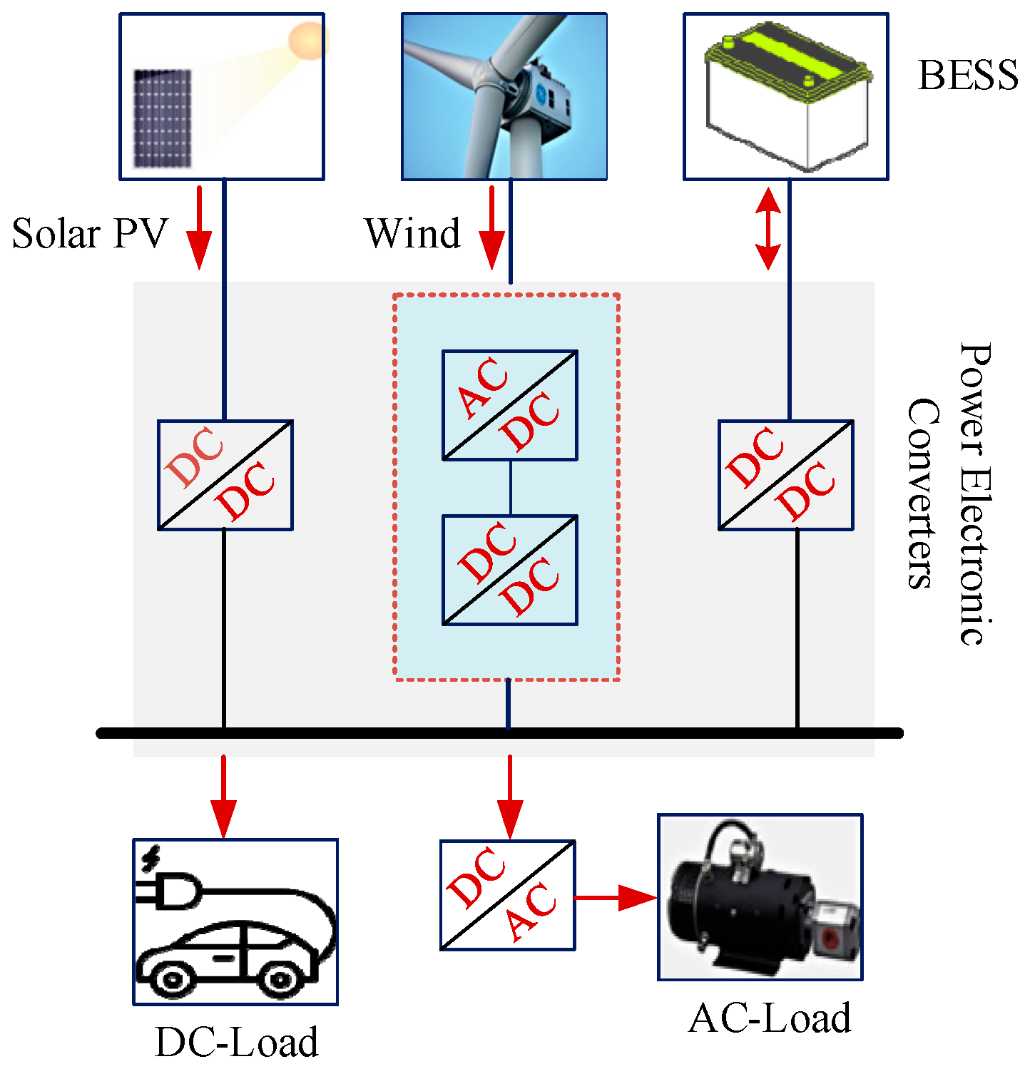
2. System Configuration
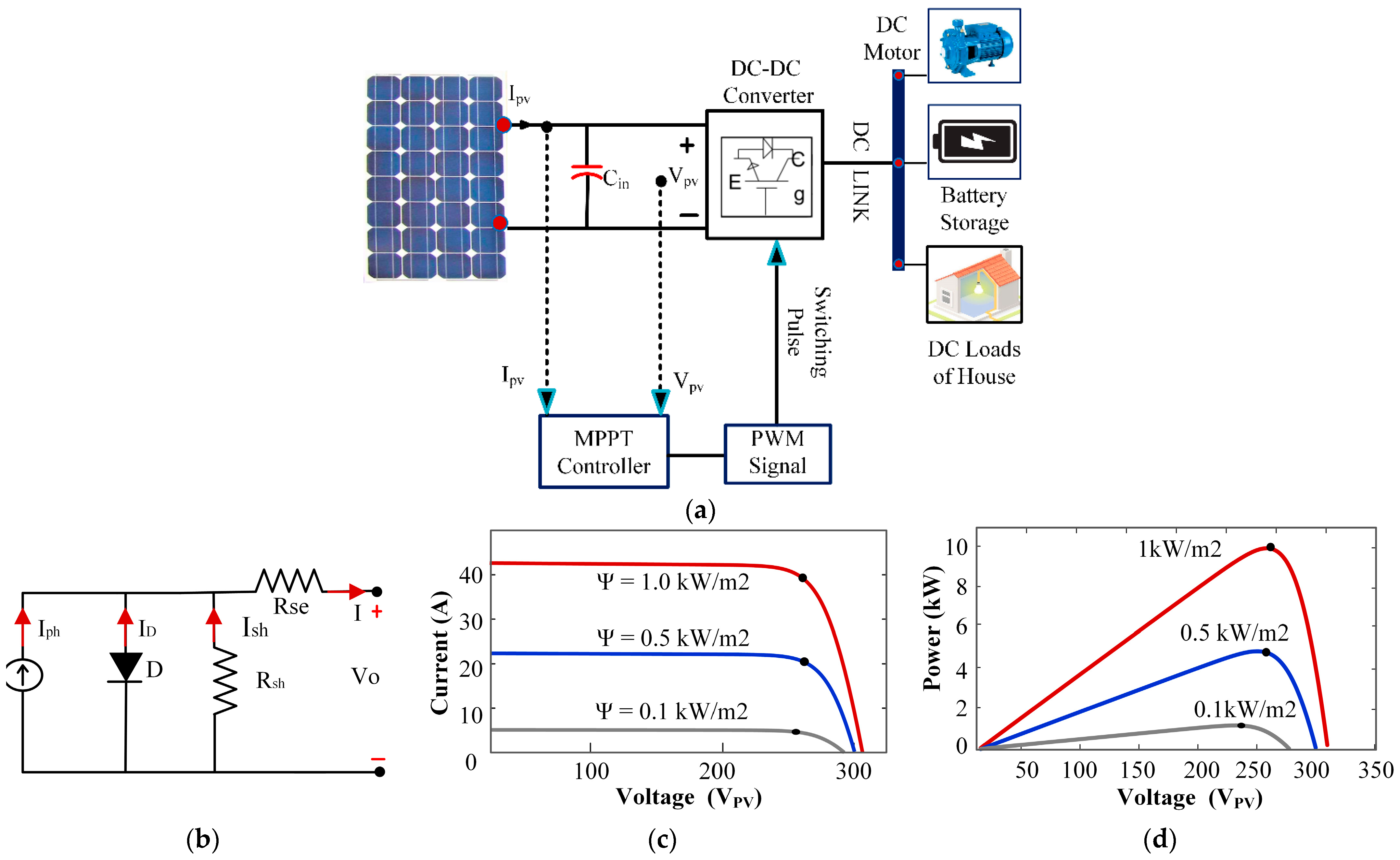
This work focuses on the performance evaluation of the non-isolated DC–DC converter converters. Non-isolated DC–DC converters are preferred for standalone PV systems due to their higher efficiency, compact design, and lower cost. They efficiently regulate voltage for battery charging and DC loads without the need for isolation, making them ideal for off-grid applications. In contrast, grid-connected PV systems often require isolated converters to ensure safety, high voltage gain, and protection against grid faults, making non-isolated converters less suitable for feeding power into the high-voltage grid. Therefore, a standalone solar PV system feeding DC load is considered. The system configuration is depicted in Figure 2a. It comprises a solar PV array, non-isolated DC–DC converters, MPPT controllers, and the DC link. The non-isolated converters are interfaced between the PV array and the DC link to regulate solar PV output. The MPPT controllers are used to provide the appropriate switching signal to the converters to obtain maximum power. The mathematical modeling of each converter is designed based on the switch-mode operation.

2.1. Solar PV Array

Figure 2b shows a single-diode model of a PV cell. The panel cells are arranged in series and parallel combinations to obtain the required rating. The I/V and P/V characteristics of the solar PV array designed for the system are shown in Figure 2c,d, respectively.
From the circuit analysis of the single-diode PV model shown in Figure 2b,
I = I p h I D I s h
The current across the shunt resistance (Ish),
I s h = V + I R s e / R s h  
The current across the Diode (ID),
  I D = I o exp V + I R se V T
The output current of a solar cell can be expressed as,
I = I ph - I o exp V + I R se V T - V + I R se R sh    
where, Iph—photo-generated current, ID—diode current, Io—reverse saturation current, VT—Thermal Voltage, Rse—Series branch resistance, Rsh—Shunt branch resistance.

2.2. Maximum Power Point Tracker (MPPT)

Maximum power point tracking algorithms are essential for optimizing solar PV power extraction. Effective control strategies play a crucial role in ensuring stability, dynamic performance, and efficiency in non-isolated DC–DC converters. Conventional MPPT techniques such as Perturb and Observe and Incremental Conductance are widely used due to their simplicity and real-time adaptability [20]. Advanced methods like Fuzzy Logic Control [21] and Artificial Neural Networks [22] enable intelligent, adaptive control by learning from system behavior and optimizing power tracking under rapid irradiance changes. Particle Swarm Optimization [23], a nature-inspired algorithm, also enhances MPPT efficiency by dynamically adjusting control parameters.
Moreover, sophisticated techniques, such as Sliding Mode Control [24], provide robust, nonlinear control, ensuring fast convergence and high resilience against variations and partial shading. Digital control methods using microcontrollers and DSPs enable real-time adaptive control, improving system efficiency and response under dynamic conditions [25]. Integrating these advanced control strategies with MPPT techniques allows modern high-gain DC–DC converters to achieve higher reliability, efficiency, and adaptability for standalone and grid-connected PV applications. Therefore, to analyze the performance of non-isolated DC–DC converters, i.e., the analysis of the system, conventional MPPT techniques were used as they are simple and easy to implement.

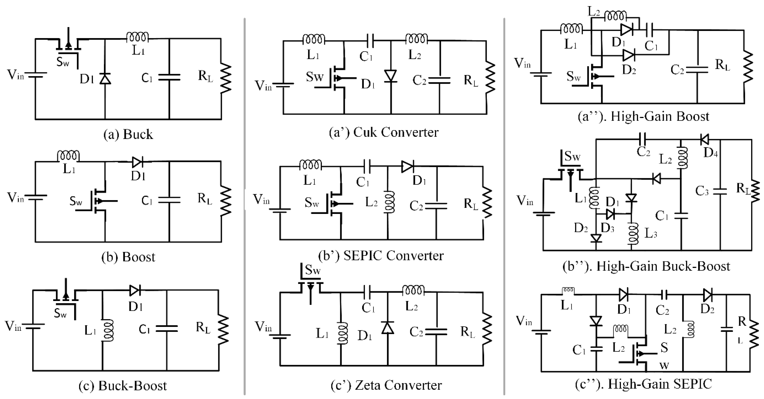
2.3. Non-Isolated DC–DC Converters

Non-isolated DC–DC converters can be broadly classified as conventional, hybrid, and high-gain converters, as depicted in Figure 3. Conventional DC–DC converters have a simple structure and easy control, while they have lower voltage gain. Hybrid DC–DC converters are designed by merging two conventional converter circuits in a single unit [26]. Due to the lower gain of these conventional hybrid converters, they also suffer from the limitations of lower gain output. On the other hand, high-gain converters are designed to have boosted output. Thus, they have a wide range of applications, especially suitable for renewable energy as solar PV systems for acquiring high voltage gain and high efficiency [27].

2.3.1. Conventional Non-Isolated DC–DC Converter

Conventional DC–DC converters can be broadly classified as buck, boost, and buck–boost converters. The buck converter works as a step-down converter; therefore, the voltage received across the load is always less than the source voltage, as shown in Figure 4a. On the other hand, the boost converter is a step-up converter; therefore, the acquired output voltage is always greater than the source voltage. In the boost operation, the diode becomes reverse-biased during the turn-on condition of the switch, and the energy is stored in the inductor. The diode becomes forward-biased when the switch is turned off, and the boosted output is obtained, as shown in Figure 4b. A buck–boost converter is a combined form of the buck and boost converters; therefore, depending on the application, it can be used as a step-up or step-down converter. In the buck–boost operation, the buck converter works as a step-down converter, whereas the boost converter performs as a step-up or boosting converter, as depicted in Figure 4c. These DC–DC converters are designed based on the converter’s switching mode operation, and the required size of passive elements is determined by the mathematical modeling of the converter, as shown in Table 1.

2.3.2. Hybrid Non-Isolated DC–DC Converters

Hybrid DC–DC converters such as Cuk, SEPIC, and Zeta are designed by hybridizing the two conventional converters, and they can also be termed derived converters or modified converters. The conventional buck and boost converters were merged into the Cuk converter, which can be used as a step-up or step-down converter. In the Cuk converter, the load side structure is a buck converter, while the front structure is a conventional boost converter, as shown in Figure 4a’. The SEPIC converter functions as both a step-up and step-down converter; it is derived from the conventional buck and boost converters at the front end and across the load terminal, respectively, as depicted in Figure 4b’. The Zeta converter is designed from the buck and buck–boost converters at the front end and across the load terminal, respectively, as depicted in Figure 4c”. Hybrid converters also have the limitation of lower voltage gain; therefore, most researchers and design engineers consider hybrid converters as a type of traditional DC–DC converter.
In [28], a boost converter is interfaced between the PV module and the resistive load to control the PMDC motor smoothly and effectively. The PI and FLC feedback controllers govern the functioning of the converter. According to the results, it was observed that the boost converter has a better response using FLC than the PI controller. The buck–boost converter is used in [29] for the induction motor drive application fed with solar PV. A bidirectional DC–DC converter is also used to control the battery’s power transfer. In [30], both the boost and the buck converters are used with the P&O and ANN-based MPPT controllers for analyzing the performance of each of the converters. A prototype model is also developed to examine the viability and performance assessments. According to the results, the buck converter outperformed the boost converter under dynamic test conditions. In [31], the buck–boost converter was implemented with solar PV, and the power was fed to the grid via the H bridge inverter. A prototype model was developed to examine viability and evaluate performance. In [32], various configurations of the converters, such as boost, Cuk, and SEPIC, are used with a closed-loop PID controller. According to the performance assessment, the SEPIC converter performed efficiently and outraced the other converters. In [33], both the positive and negative output Luo converters are interfaced with solar PV for BLDC motor drive applications. According to the simulation’s results, it was observed that the positive output Luo converter performed efficiently as compared to the negative output Luo converters. In [34], the SEPIC converter is implemented for the application of solar PV with both the MPPT controller P&O and FLC. The results showed that the SEPIC converter had less ripple and fluctuation using FLC than P&O. The comparison of different non-isolated conventional and hybrid DC–DC converter topologies are shown in Table 1.

2.3.3. High-Gain DC–DC Converter

In [35], a novel high-gain boost converter topology with fewer components—one switch, two inductors, two capacitors, and three diodes—was proposed, as shown in Figure 4a”. A prototype model was developed to examine this high-gain converter’s viability and performance evaluation for application in solar PV and hybrid vehicles. In [36], a novel high-gain buck–boost converter topology was proposed, as shown in Figure 4b”, which consists of three inductors, three capacitors, five diodes, and a single switch. The output voltage of this high-gain converter can be stepped up/down in accordance with the requirements of the application. In [37], a novel topology of the high-gain SEPIC converter was proposed, as shown in Figure 4c”, which is derived from the conventional SEPIC converter and has a single switch, three inductors, three capacitors, and three diodes. A prototype model was developed to examine this high-gain converter’s viability and performance evaluation in renewable energy applications.
In [38], a novel extended zeta converter circuit based on a high-voltage gain was presented for PV applications. This topology was developed by combining a high-voltage gain converter and a conventional Zeta converter to overcome the limitations of voltage gain in conventional Zeta converters. An experimental prototype was set up to validate the simulation results. According to [39], a conventional double boost and conventional SEPIC converter were merged into an integrated double boost converter, increasing the proposed converter’s voltage gain. This converter is suitable for PV and FC applications since it has a low input current ripple. This high-gain converter also had a lesser weight, size, and simple structure, and performed efficiently. The proposed converter in [40] combines the features of the quadratic boost and Cuk converters to increase voltage gain as well as provide simple control. Drops in the inductor and resistor and across the power switch caused a minor difference between the simulation and the experimental results. According to [41], a novel high-gain boost converter is implemented with a hybrid PV system that includes solar PV, a battery bank, and a bidirectional DC–DC converter. Using battery bank as a hybrid source, the high gain converter regulates the output across the DC link, and a bidirectional converter is used to maintain the system’s performance under dynamic test conditions. The bidirectional converter charges and discharges the battery in the buck and boost modes. A novel high-gain converter is presented in [42], based on a quadratic boost and voltage multiplier cell combination. Since it has an input inductor, it performs better in FC applications due to fewer ripples in the input current. The converter discussed in [43] is the combined form of the buck and buck–boost converters with an additional inductor added to the buck–boost converter to overcome the limitations of the standard buck–boost converter, and simulation results were validated by an experimental setup. In [44], both the unidirectional and bidirectional converters are used to maintain the adequate performance of the hybrid system. The proposed topology is based on cascaded converters, which provide high voltage gain. The comparison of different non-isolated high-gain DC–DC converter topologies is shown in Table 2.
A non-isolated interleaved boost converter is developed in [45], which provides an efficient, compact, and high-performance solution for high-voltage applications. The converter employs coupled inductors, active clamping, and a voltage multiplier circuit to minimize switching losses, reduce voltage stress, and achieve soft switching. A non-isolated Z-source DC–DC converter is designed for high step-up photovoltaic (PV) applications [46]. The converter achieves a higher voltage gain while maintaining low voltage stress on semiconductor devices. Unlike traditional boost converters, which require extreme duty cycles to achieve high voltage gain, this design enhances efficiency by using a voltage multiplier and a coupled inductor network. The circuit ensures soft switching, eliminating reverse recovery issues in output diodes, thereby reducing power losses. Additionally, the clamped switch voltage improves device reliability, while the low duty cycle operation minimizes switching stress. In [47], a non-isolated quasi-Z-source (QZS)-based high-gain DC–DC converter with switched capacitors is developed to overcome the limitations of traditional Z-source converters, such as low voltage gain, high voltage stress, and discontinuous input current. The QZS converter achieves high voltage gain for a duty cycle of less than 0.5 while maintaining continuous input current and reduced voltage stress on switching components. A high-gain, high-efficiency SEPIC-based DC–DC converter for renewable energy applications is proposed in [48], integrating a quasi-resonant topology with a coupled inductor and voltage multiplier circuit. The circuit achieves high voltage gain without extreme duty cycles, reducing voltage stress across switching components. The soft-switching (zero-current switching, ZCS) operation minimizes switching losses, while the lossless passive clamp circuit recycles leakage energy, enhancing efficiency. The converter also ensures continuous input current with low ripple, making it ideal for photovoltaic (PV) and other renewable systems. In [49], a non-inverting buck–boost converter enhances efficiency by ensuring soft-switching for all transistors, significantly reducing switching losses. The circuit employs a triple coupled inductor, two resonant inductors, and auxiliary diodes, which enable continuous current flow through the main inductor, thereby minimizing current ripple and improving power quality. A multi-input boost DC–DC converter is designed in [50] for renewable energy systems, ensuring continuous input and output currents, which improve system reliability and efficiency. Unlike conventional converters, it integrates multiple input sources such as PV panels, batteries, and fuel cells, enabling flexible power management. The boost topology with continuous current flow minimizes ripple, reduces filter size, and extends component lifespan.

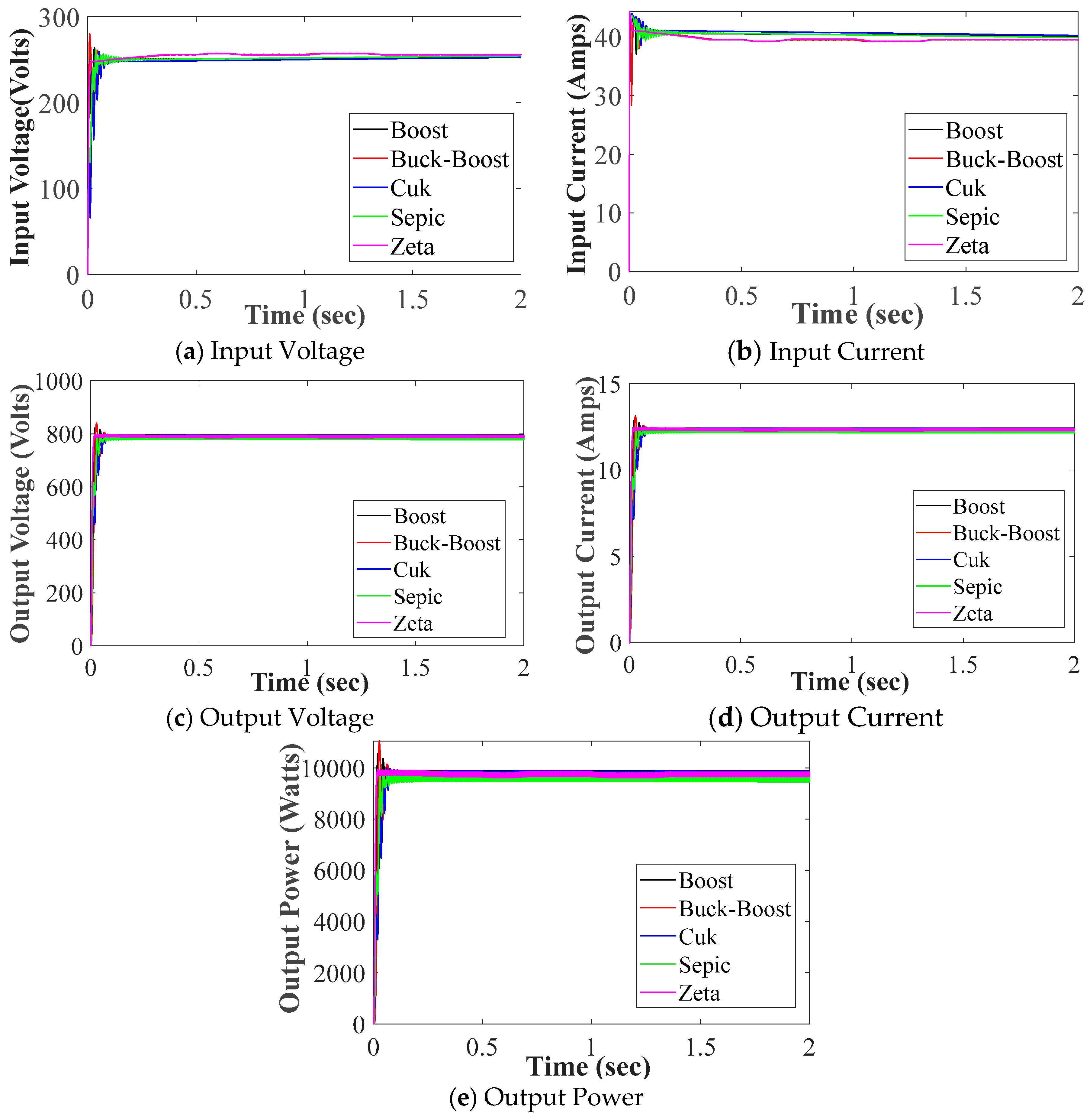
3. Performance Analysis for Optimal Selection of the Converter

The critical analysis of selected non-isolated DC–DC converters, such as conventional, hybrid, and high-gain DC–DC converters, is presented in this section. In order to evaluate the performance of the converters, each topology is examined based on an output response, conversion parameters such as duty ratio, efficiency, and the required application. To examine the performance of non-isolated DC–DC converters, the selected topologies were implemented with the solar PV system and analyzed based on Simulink results. The mathematical modeling of each configuration is designed based on the switch-mode operation. Both the P&O and INC MPPT controllers are used to validate the performance of the circuit topology. Table 3 shows the parameters of the PV module used.

3.1. Conventional and Hybrid DC–DC Converter

The conventional and hybrid DC–DC converters are positioned between the PV array and the load terminal to step up the voltage from 250 V to 800 V. The P&O MPPT controller provides the switching pulse to the converters to acquire the desired response from the SPV system. The passive elements of the converters are designed based on switch mode operation as defined in Table 4 and Table 5, and the mathematical analysis of the circuits is validated through the simulation results shown in Figure 5. In this section, each converter’s critical analysis and performance are evaluated in terms of passive elements, output voltage and current, output power, output parameter stability, and the efficiency of the SPV system, as shown in Table 6.
As per the obtained results, the Zeta converter performed efficiently despite the limitations of higher fluctuations across the DC link, as shown in Figure 5. The Cuk converter had fewer fluctuations in output voltage and current than boost, buck–boost, and Zeta converters but required a higher number and size of passive components. Among all conventional and hybrid DC–DC converters, the Boost converter had the fewest passive elements and performed efficiently except for the Zeta converter for this solar PV-based application.

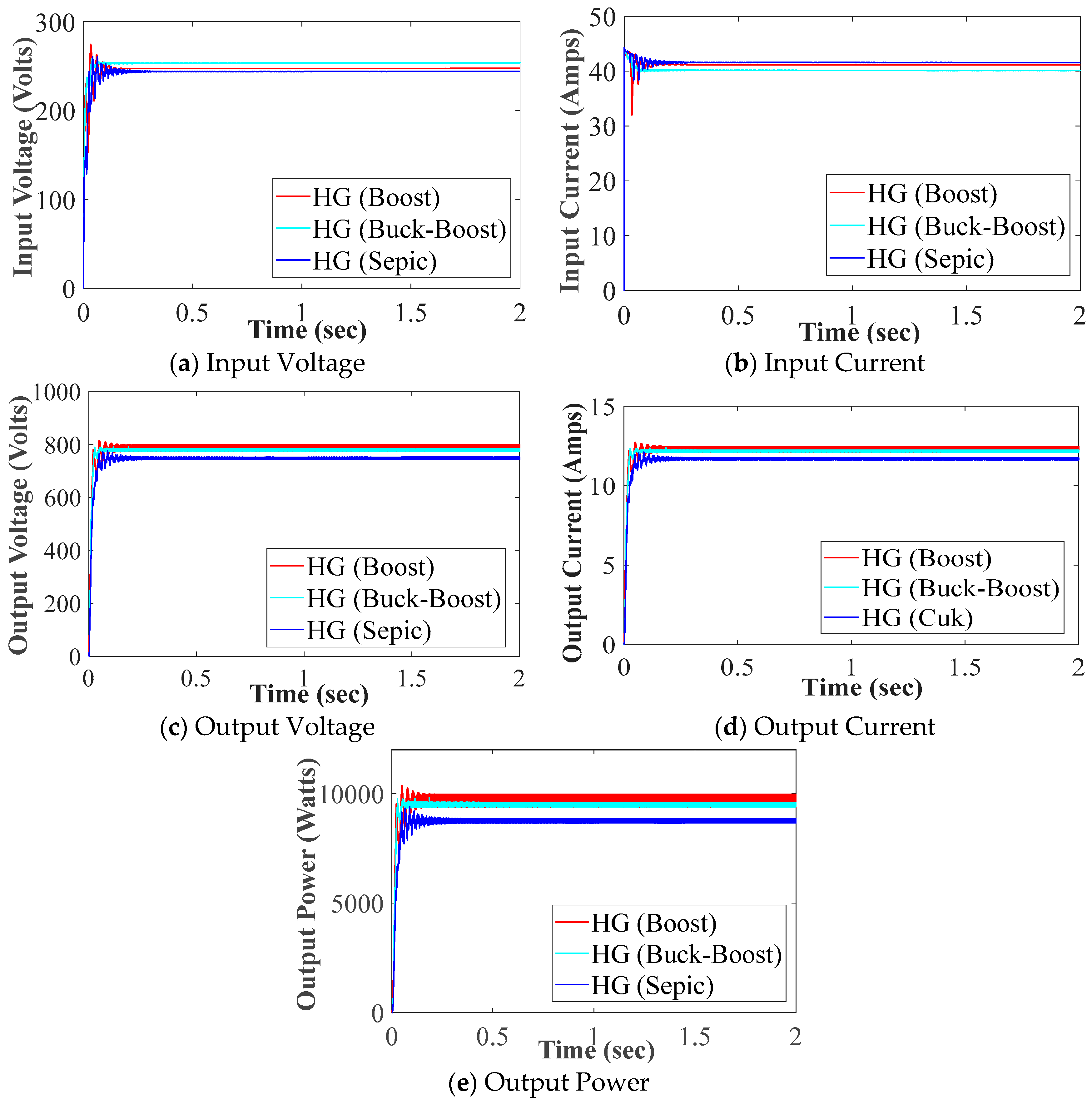
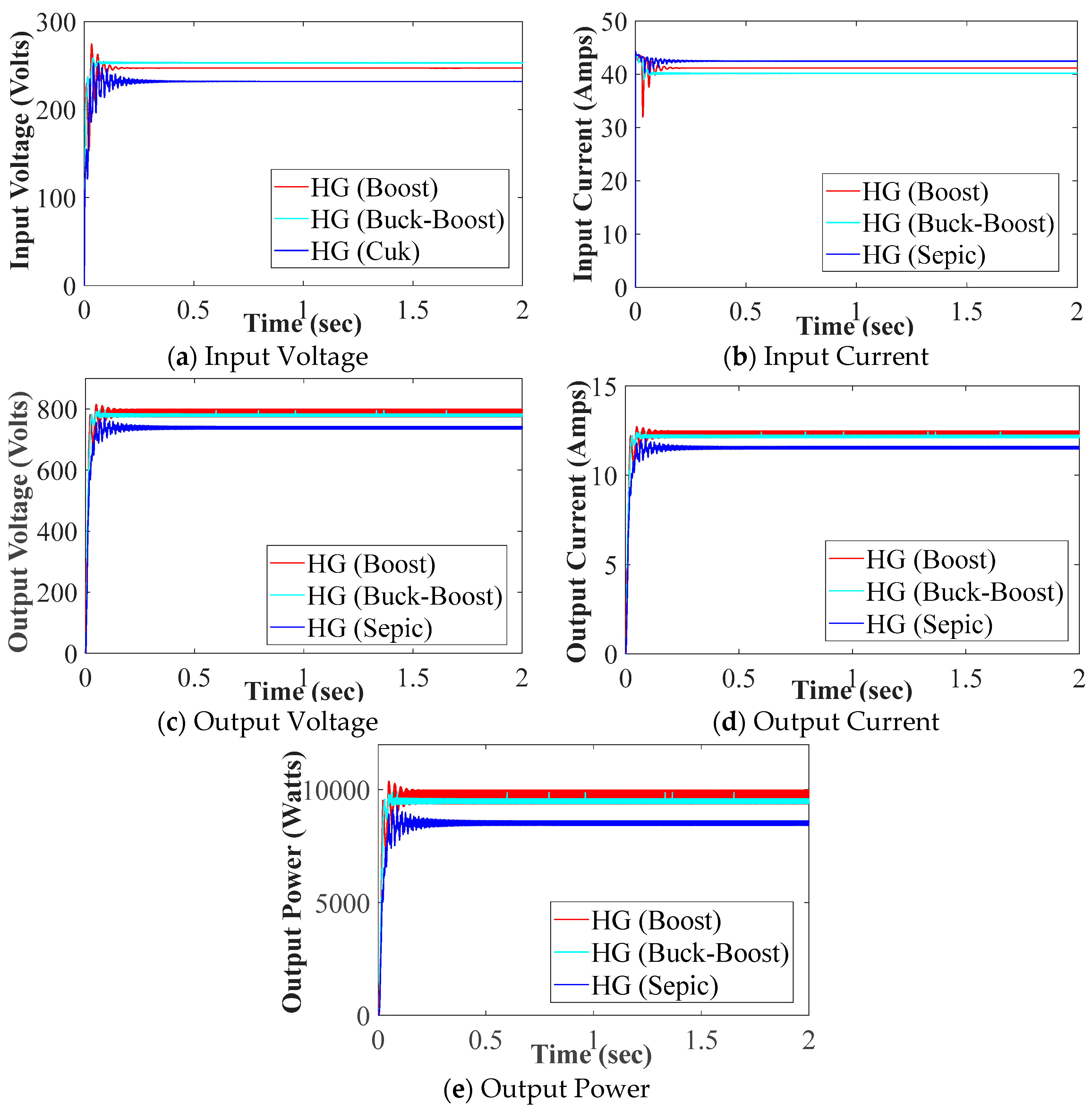
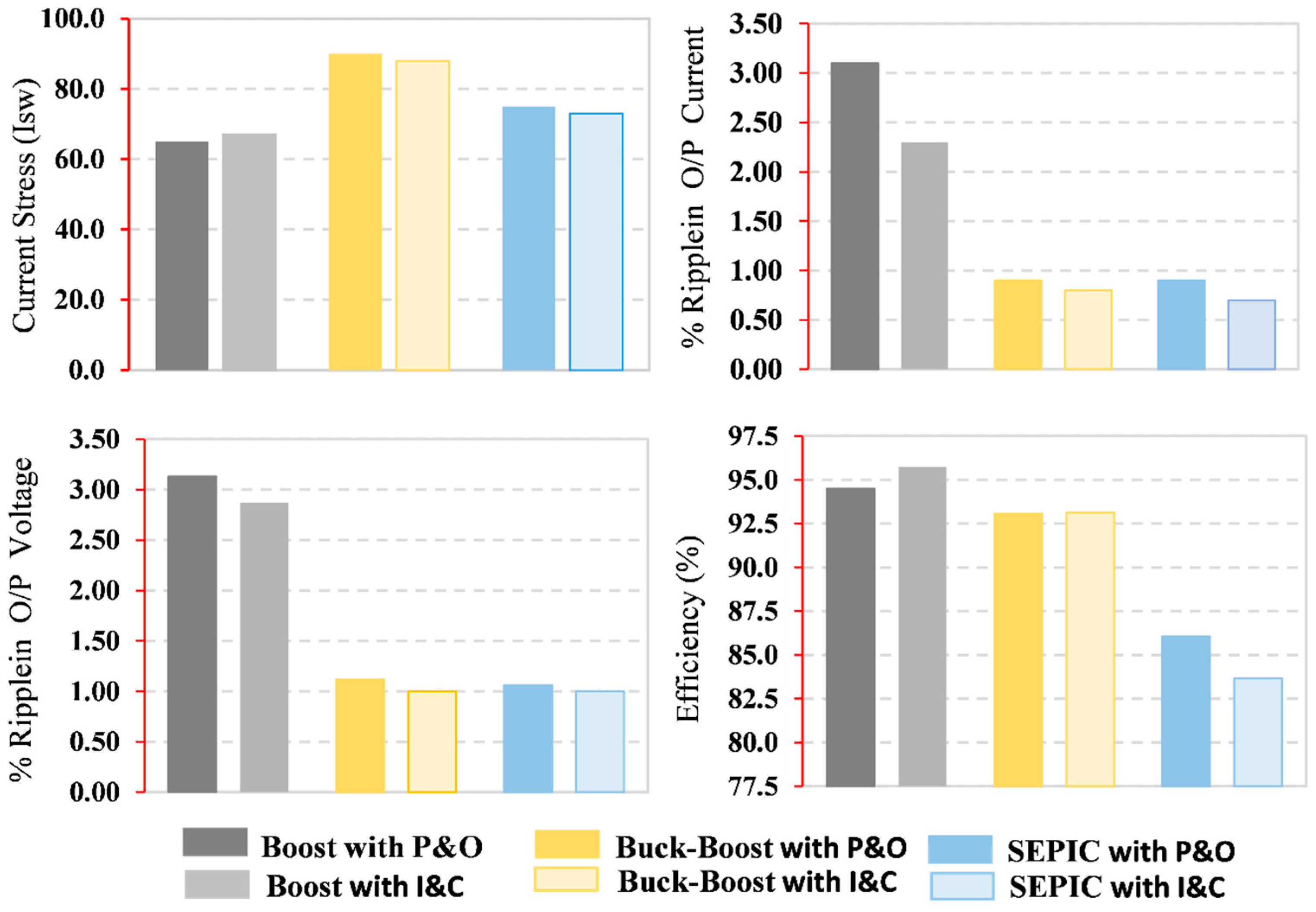
3.2. High-Gain DC–DC Converters

Various configurations of a recently proposed high-gain DC–DC converter integrated with a solar PV system are examined in this article. These high-gain converters are implemented with a 10 KW SPV system, where high-gain DC–DC converters boost the solar PV array from 250V, as obtained across the DC link, to 800 V output voltage. The P&O and INC-based MPPT controllers provided the switching pulse to the high-gain converters to acquire the maximum power. Each converter’s performance is analyzed in terms of output voltage and current, output power, efficiency, DC link fluctuations, and the required size of passive components. The converters’ mathematical modeling and performance analysis are carried out and verified through MATLAB/Simulink 2018a, as shown in Table 7 and Table 8. According to the simulation results, the boost converters provided higher efficiency but had more output voltage, current, and power fluctuations across the DC link, as shown in Figure 6 and Figure 7. It is evident from the figures that the boost converter with I&C delivers the highest output power of 9759 W with an efficiency of 95.68%, followed by the boost with P&O. The buck–boost and SEPIC converters have slightly lower output power and efficiency. The comparison of high-gain converters in terms of current stress, output ripple, and efficiency is illustrated in Figure 8. As shown in Figure 8 the high-gain buck–boost converter experiences higher current stress on semiconductor devices than the boost and SEPIC converters. Additionally, Figure 8 illustrates that the buck–boost and SEPIC exhibits lower output voltage current ripple than the boost converter. However, the boost converter achieves higher efficiency, as depicted in Figure 8.

4. Conclusions

This paper critically analyzes and evaluates the performance of selected non-isolated DC–DC converters, specifically conventional, hybrid, and high-gain topologies for solar photovoltaic (PV) applications. The selected topologies were modelled in MATLAB/Simulink and analyzed based on different performance parameters, including output voltage, current, efficiency, and fluctuations across the DC link. The results show that the Zeta converter, with an efficiency of 96.35%, outperformed other conventional and hybrid converter topologies. Although the boost converter has less efficiency than the Zeta converter, it requires fewer and smaller passive components, making it a preferred choice for cost-sensitive applications. In high-gain converters, the boost converter has an efficiency of 94.52%, the highest among all converters, making it well-suited for grid-connected PV systems, while the SEPIC converter demonstrates the lowest voltage and current ripple of 1%, ideal for sensitive DC loads and hybrid PV-battery systems. Additionally, the study shows that Incremental Conductance (INC) outperforms Perturb and Observe (P&O), making it the preferred choice for faster and more accurate MPPT tracking in non-isolated DC–DC converter systems. This comprehensive study provides valuable insights for design engineers and researchers, assisting in the selection of the most suitable DC–DC converter for solar PV applications.

Author Contributions

Conceptualization, K.M. and M.S.B.A.; methodology, M.S.B.A. and M.I.M.; validation, K.M. and M.S.B.A.; formal analysis, K.M.; writing—original draft preparation, K.M. and M.S.B.A.; writing—review and editing, M.S.B.A., M.I.M., M.F.A. and M.A.; supervision, M.S.B.A. All authors have read and agreed to the published version of the manuscript.

Funding

This research received no external funding.

Data Availability Statement

No new data were created or analyzed in this study. Data sharing is not applicable to this article.

Conflicts of Interest

The authors declare no conflicts of interest.

References

  1. Amin, M.A.; Suleman, A.; Waseem, M.; Iqbal, T.; Aziz, S.; Faiz, M.T.; Zulfiqar, L.; Saleh, A.M. Renewable Energy Maximization for Pelagic Islands Network of Microgrids Through Battery Swapping Using Deep Reinforcement Learning. IEEE Access 2023, 11, 86196–86213. [Google Scholar] [CrossRef]
  2. Wang, Z.; Madawala, U.K. Modelling and analysis of grid integrated TSCAOI generators for renewable distributed generation systems. CPSS Trans. Power Electron. Appl. 2020, 5, 372–387. [Google Scholar] [CrossRef]
  3. Ashique, R.H.; Shihavuddin, A.S.M.; Khan, M.M.; Islam, A.; Ahmed, J.; Arif, M.S.B.; Maruf, M.H.; Al Mansur, A.; Haq, M.A.u.; Siddiquee, A. An Analysis and Modeling of the Class-E Inverter for ZVS/ZVDS at Any Duty Ratio with High Input Ripple Current. Electronics 2021, 10, 1312. [Google Scholar] [CrossRef]
  4. Ado, M.; BinArif, M.S.; Jusoh, A.; Mutawakkil, A.U.; Danmallam, I.M. Buck-boost converter with simple gate control for renewable energy applications. Energy Sources Part A Recovery Util. Environ. Eff. 2024, 46, 17021–17033. [Google Scholar] [CrossRef]
  5. Mohammad, K.; Ahad, A.; bin Arif, M.S.; Ashique, R.H. Critical Analysis and Performance Evaluation of Solar PV-System Implementing Non-Isolated DC-DC Converters. In Proceedings of the 2021 3rd International Conference on Sustainable Technologies for Industry 4.0 (STI), Dhaka, Bangladesh, 18–19 December 2021; pp. 1–6. [Google Scholar] [CrossRef]
  6. Luo, P.; Guo, L.; Xu, J.; Li, X. Analysis and Design of a New Non-Isolated Three-Port Converter with High Voltage Gain for Renewable Energy Applications. IEEE Access 2021, 9, 115909–115921. [Google Scholar] [CrossRef]
  7. Li, C.; Li, H.; Cheng, L.; Sun, X.; Wang, N.; Li, W. A Novel Non-Isolated Dual-Input Single-Output High Step-Up DC/DC Converter with Coupled Inductors. IEEE Trans. Power Electron. 2023, 38, 11556–11567. [Google Scholar] [CrossRef]
  8. Alajmi, B.N.; Marei, M.I.; Abdelsalam, I.; Ahmed, N.A. Multiphase interleaved converter based on cascaded non-inverting buck-boost converter. IEEE Access 2022, 10, 42497–42506. [Google Scholar] [CrossRef]
  9. Cheng, T.; Lu, D.D.-C.; Qin, L. Non-Isolated Single-Inductor DC/DC Converter with Fully Reconfigurable Structure for Renewable Energy Applications. IEEE Trans. Circuits Syst. II Express Briefs 2018, 65, 351–355. [Google Scholar] [CrossRef]
  10. Shanthi, T.; Prabha, S.U.; Sundaramoorthy, K. Non-Isolated n-Stage High Step-up DC-DC Converter for Low Voltage DC Source Integration. IEEE Trans. Energy Convers. 2021, 36, 1625–1634. [Google Scholar] [CrossRef]
  11. Givi, H.; Farjah, E.; Ghanbari, T. A Comprehensive Monitoring System for Online Fault Diagnosis and Aging Detection of Non-Isolated DC–DC Converters’ Components. IEEE Trans. Power Electron. 2019, 34, 6858–6875. [Google Scholar] [CrossRef]
  12. Seguel, J.L.; Seleme, S.I., Jr.; Morais, L.M.F. Comparative study of Buck-Boost, SEPIC, Cuk and Zeta DC-DC converters using different MPPT methods for photovoltaic applications. Energies 2022, 15, 7936. [Google Scholar] [CrossRef]
  13. Amir, A.; Amir, A.; Che, H.S.; Elkhateb, A.; Rahim, N.A. Comparative analysis of high voltage gain DC-DC converter topologies for photovoltaic systems. Renew. Energy 2019, 136, 1147–1163. [Google Scholar] [CrossRef]
  14. Wai, R.-J.; Lin, C.-Y.; Duan, R.-Y.; Chang, Y.-R. High-efficiency DC-DC converter with high voltage gain and reduced switch stress. IEEE Trans. Ind. Electron. 2007, 54, 354–364. [Google Scholar] [CrossRef]
  15. Forouzesh, M.; Siwakoti, Y.P.; Gorji, S.A.; Blaabjerg, F.; Lehman, B. Step-up DC–DC converters: A comprehensive review of voltage-boosting techniques, topologies, and applications. IEEE Trans. Power Electron. 2017, 32, 9143–9178. [Google Scholar] [CrossRef]
  16. Rafin, S.M.S.H.; Ahmed, R.; Haque, A.; Hossain, K.; Haque, A.; Mohammed, O.A. Power electronics revolutionized: A comprehensive analysis of emerging wide and ultrawide bandgap devices. Micromachines 2023, 14, 2045. [Google Scholar] [CrossRef]
  17. Ashique, R.H.; Salam, Z.; Maruf, H.; Shihavuddin, A.; Islam, T.; Rahman, F.; Kotsampopoulos, P.; Fayek, H.H. A comparative analysis of soft switching techniques in reducing the energy loss and improving the soft switching range in power converters. Electronics 2022, 11, 1062. [Google Scholar] [CrossRef]
  18. Du, R.; Samavatian, V.; Samavatian, M.; Gono, T.; Jasiński, M. Development of a High-Gain Step-Up DC/DC Power Converter with Magnetic Coupling for Low-Voltage Renewable Energy. IEEE Access 2023, 11, 90038–90051. [Google Scholar] [CrossRef]
  19. Lakshmi, M.; Hemamalini, S. Non-isolated High Gain DC–DC Converter for DC Microgrids. IEEE Trans. Ind. Electron. 2018, 65, 1205–1212. [Google Scholar] [CrossRef]
  20. Rajani, S.V.; Pandya, V.J. Simulation and comparison of perturb and observe and incremental conductance MPPT algorithms for solar energy system connected to grid. Sadhana 2015, 40, 139–153. [Google Scholar] [CrossRef]
  21. Robles Algarín, C.; Taborda Giraldo, J.; Rodríguez Álvarez, O. Fuzzy logic based MPPT controller for a PV system. Energies 2017, 10, 2036. [Google Scholar] [CrossRef]
  22. Villegas-Mier, C.G.; Rodriguez-Resendiz, J.; Álvarez-Alvarado, J.M.; Rodriguez-Resendiz, H.; Herrera-Navarro, A.M.; Rodríguez-Abreo, O. Artificial neural networks in MPPT algorithms for optimization of photovoltaic power systems: A review. Micromachines 2021, 12, 1260. [Google Scholar] [CrossRef]
  23. Koad, R.B.A.; Zobaa, A.F.; El-Shahat, A. A novel MPPT algorithm based on particle swarm optimization for photovoltaic systems. IEEE Trans. Sustain. Energy 2016, 8, 468–476. [Google Scholar]
  24. Ahmad, F.F.; Ghenai, C.; Hamid, A.K.; Bettayeb, M. Application of sliding mode control for maximum power point tracking of solar photovoltaic systems: A comprehensive review. Annu. Rev. Control 2020, 49, 173–196. [Google Scholar]
  25. Bhat, S.; Nagaraja, H.N. DSP based proportional integral sliding mode controller for photo-voltaic system. Int. J. Electr. Power Energy Syst. 2015, 71, 123–130. [Google Scholar]
  26. Zakaria, A.; Marei, M.I.; Mashaly, H.M. A hybrid interleaved DC-DC converter Based on buck-Boost topologies for medium voltage applications. e-Prime-Adv. Electr. Eng. Electron. Energy 2023, 6, 100301. [Google Scholar]
  27. Bhaskar, M.S.; Ramachandaramurthy, V.K.; Padmanaban, S.; Blaabjerg, F.; Ionel, D.M.; Mitolo, M.; Almakhles, D. Survey of DC-DC non-isolated topologies for unidirectional power flow in fuel cell vehicles. IEEE Access 2020, 8, 178130–178166. [Google Scholar]
  28. Mohamed, H.A.; Khattab, H.A.; Mobarka, A.; Morsy, G.A. Design, control and performance analysis of DC-DC boost converter for stand-alone PV system. In Proceedings of the 2016 Eighteenth International Middle East Power Systems Conference (MEPCON), Cairo, Egypt, 27–29 December 2016; pp. 101–106. [Google Scholar] [CrossRef]
  29. Vtas, P.; Pal, Y. Solar PV array buck-boost converter fed single phase induction motor drives for water pumping. In Proceedings of the 2017 International Conference on Information, Communication, Instrumentation and Control (ICICIC), Indore, India, 17–19 August 2017; pp. 1–5. [Google Scholar] [CrossRef]
  30. Chu, Y.-T.; Yuan, L.-Q.; Chiang, H.-H. ANFIS-based maximum power point tracking control of PV modules with DC-DC converters. In Proceedings of the 2015 18th International Conference on Electrical Machines and Systems (ICEMS), Pattaya, Thailand, 25–28 October 2015; pp. 692–697. [Google Scholar] [CrossRef]
  31. Patil, S.N.; Prasad, R.C. Design and development of MPPT algorithm for high efficient DC-DC converter for solar energy system connected to grid. In Proceedings of the 2015 International Conference on Energy Systems and Applications, Pune, India, 30 October–1 November 2015; pp. 228–233. [Google Scholar] [CrossRef]
  32. Kumar, S.; Kumar, R.; Singh, N. Performance of closed loop SEPIC converter with DC-DC converter for solar energy system. In Proceedings of the 2017 4th International Conference on Power, Control & Embedded Systems (ICPCES), Allahabad, India, 9–11 March 2017; pp. 1–6. [Google Scholar] [CrossRef]
  33. Saravanan, R.; Chandrasekaran, N.; Rajalakshmi, K. Design and Simulation Analysis of Various Luo Converter Topologies fed BLDC Drive for Solar PV Applications. In Proceedings of the 2020 6th International Conference on Advanced Computing and Communication Systems (ICACCS), Coimbatore, India, 6–7 March 2020; pp. 1120–1123. [Google Scholar] [CrossRef]
  34. Chandran, A.; Reshmi, V.; Mathew, B.K. Comparative Analysis of P&O and FLC based SEPIC Boost Converter for Solar PV Application. In Proceedings of the 2020 Third International Conference on Smart Systems and Inventive Technology (ICSSIT), Tirunelveli, India, 20–22 August 2020; pp. 616–621. [Google Scholar] [CrossRef]
  35. Rafiq, U.; Murtaza, A.F.; Sher, H.A.; Gandini, D. Design and Analysis of a Novel High-Gain DC-DC Boost Converter with Low Component Count. Electronics 2021, 10, 1761. [Google Scholar] [CrossRef]
  36. Sarikhani, A.; Allahverdinejad, B.; Torkaman, H. A non-isolated buck-boost DC-DC converter with single switch. In Proceedings of the 2018 9th Annual Power Electronics, Drives Systems and Technologies Conference (PEDSTC), Tehran, Iran, 13–15 February 2018; pp. 369–373. [Google Scholar] [CrossRef]
  37. Maroti, P.K.; Padmanaban, S.; Nielsen, J.B.-H.; Bhaskar, M.S.; Meraj, M.; Alammari, R.; Iqbal, A. A New Structure of High Voltage Gain SEPIC Converter for Renewable Energy Applications. IEEE Access 2019, 7, 89857–89868. [Google Scholar] [CrossRef]
  38. Hosseini, S.H.; Alishah, R.S.; Kurdkandi, N.V. Design of a new extended zeta converter with high voltage gain for photovoltaic applications. In Proceedings of the 2015 9th International Conference on Power Electronics and ECCE Asia (ICPE-ECCE Asia), Seoul, Republic of Korea, 1–5 June 2015; pp. 970–977. [Google Scholar] [CrossRef]
  39. Sabzali, A.J.; Ismail, E.H.; Behbehani, H.M. High voltage step-up integrated double Boost–Sepic DC–DC converter for fuel-cell and photovoltaic applications. Renew. Energy 2015, 82, 44–53. [Google Scholar]
  40. Pires, V.F.; Cordeiro, A.; Foito, D.; Silva, J.F. High Step-Up DC–DC Converter for Fuel Cell Vehicles Based on Merged Quadratic Boost–Ćuk. IEEE Trans. Veh. Technol. 2019, 68, 7521–7530. [Google Scholar] [CrossRef]
  41. Shahir, F.M.; Aberoumandazar, M.; Babaei, E. High Gain DC-DC Boost Converter Applied in Hybrid System of Photovoltaic and Battery. In Proceedings of the 2021 International Symposium on Devices, Circuits and Systems (ISDCS), Higashihiroshima, Japan, 3–5 March 2021; pp. 1–4. [Google Scholar] [CrossRef]
  42. Navamani, J.D.; Vijayakumar, K.; Jegatheesan, R. Non-isolated high gain DC-DC converter by quadratic boost converter and voltage multiplier cell. Ain Shams Eng. J. 2018, 9, 1397–1406. [Google Scholar] [CrossRef]
  43. Chandrasekar, B.; Nallaperumal, C.; Padmanaban, S.; Bhaskar, M.S.; Holm-Nielsen, J.B.; Leonowicz, Z.; Masebinu, S.O. Non-Isolated High-Gain Triple Port DC–DC Buck-Boost Converter with Positive Output Voltage for Photovoltaic Applications. IEEE Access 2020, 8, 113649–113666. [Google Scholar] [CrossRef]
  44. Navamani, J.D.; Geetha, A.; Almakhles, D.; Lavanya, A.; Ali, J.S.M. Modified LUO High Gain DC-DC Converter with Minimal Capacitor Stress for Electric Vehicle Application. IEEE Access 2021, 9, 122335–122350. [Google Scholar] [CrossRef]
  45. Girish Ganesan, R.; Prabhakar, M. Non-isolated high step-up interleaved boost converter. Int. J. Power Electron. 2014, 6, 288–303. [Google Scholar] [CrossRef]
  46. Torkan, A.; Ehsani, M. A novel nonisolated Z-source DC–DC converter for photovoltaic applications. IEEE Trans. Ind. Appl. 2018, 54, 4574–4583. [Google Scholar] [CrossRef]
  47. Mahmood, A.; Zaid, M.; Khan, S.; Siddique, M.D.; Iqbal, A.; Sarwer, Z. A non-isolated quasi-Z-source-based high-gain DC–DC converter. Int. J. Circuit Theory Appl. 2022, 50, 653–682. [Google Scholar] [CrossRef]
  48. Hasanpour, S.; Forouzesh, M.; Siwakoti, Y.P.; Blaabjerg, F. A new high-gain, high-efficiency SEPIC-based DC–DC converter for renewable energy applications. IEEE J. Emerg. Sel. Top. Ind. Electron. 2021, 2, 567–578. [Google Scholar] [CrossRef]
  49. Abdel-Rahim, O.; Chub, A.; Blinov, A.; Vinnikov, D.; Peftitsis, D. An efficient non-inverting buck-boost converter with improved step up/down ability. Energies 2022, 15, 4550. [Google Scholar] [CrossRef]
  50. Gorji, S.A.; Sahebi, H.G.; Movahed, M.; Ektesabi, M. Multi-input Boost DC-DC converter with continuous input-output current for Renewable Energy Systems. In Proceedings of the 2019 IEEE 4th International Future Energy Electronics Conference (IFEEC), Singapore, 25–28 November 2019. [Google Scholar]
Figure 1. Applications of Different PECs.
Energies 18 01572 g001
Figure 2. Components of PV system, PV cell model, and characteristics of a solar PV Array: (a) General Architecture of a PV System; (b) Single diode Model of a PV cell; (c) I/V Characteristics; (d) P/V Characteristics.
Energies 18 01572 g002
Figure 3. Classification of non-isolated DC–DC converters.
Energies 18 01572 g003
Figure 4. Circuit configurations of different selected DC–DC converter topologies.
Energies 18 01572 g004
Figure 5. Input and output responses of the selected non-isolated high-gain converters.
Energies 18 01572 g005
Figure 6. Performance analysis of high-gain converters with P&O MPPT controller.
Energies 18 01572 g006
Figure 7. Performance analysis of high-gain converters with INC MPPT controller.
Energies 18 01572 g007
Figure 8. Current stress, output voltage and current ripple, and efficiency comparisons of high-gain converters.
Energies 18 01572 g008
Table 1. Comprehensive review of different non-isolated conventional and hybrid DC–DC converter topologies.
Ref.ConverterVoltage Gain (VG.)NSNLNCNDPower
(W)
VO
(V)
ControlApplication
[28]Boost 1 ( 1 D ) 111187828.00PI + FLCStandalone PV
[29]Buck-Boost D ( 1 D ) 12112190350.00INC + VSISingle-phase IM fed with solar PV
[30]Buck/BoostD11115017.20P&O + ANFISPV System
[31]Buck-Boost D ( 1 D ) 121110024.00IC + PLLPV grid integration
[32]SEPIC D ( 1 D ) 12212024489.30PIDPV
[33]LUO D ( 1 D ) 12216000210.00INC + VSIBLDC Motor fed with PV
[34]SEPIC D ( 1 D ) 1221200230.00P&O + FLCPV
NS—number of switches, NL—Number of inductors, NC—Number of capacitors, ND—Number of diodes.
Table 2. Comprehensive Review Summary of Non-Isolated High-Gain DC–DC Converters.
Ref.Voltage Gain (VG.)NSNLNCNDVO
(V)
Power
(W)
Efficiency
(% η )
Frequency
(kHz)
App.
[38] 4 D ( 1 D ) 626522010091.0010PV
[39] 2 + D ( 1 D ) 125424010097.8350PV
&
FC
[40] 1 + D ( 1 D ) 2 134420025094.0020FC
[41] 1 D ( 1 D ) 122270027.9398.7940PV
[42] 1 ( 1 D ) 2 1223964088.0060FC
[43] D 2 ( 1 D ) 2 43242420093.6020PV
[44] ( 2 D ) ( 1 + D ) D 2 235446.45090.2550EV
NS—number of switches, NL—Number of inductors, NC—Number of capacitors, ND—Number of diodes.
Table 3. Specification of the PV panel used.
Panel ParametersValues
The maximum Power rating of a panel, Pm255 W
Open circuit voltage of panel, Voc38.46 V
Rating of Short circuit current, Isc8.89 A
Current at Maximum Power, Im8.16 A
The voltage at Maximum Power, Vm31.24 V
Current temperature coefficient, KT0.07
Voltage temperature coefficient, Kv−0.35601
Number of panels in series Ns08
Number of panels in parallel Np05
Table 4. Designing Parameters of Conventional & Hybrid DC-DC Converters.
Converter TypeL1 (mH)L2 (mH)C1 (µf)C2 (µf)RL (Ω)
Boost Converter27.50-107-64
Buck–Boost30.47-119-64
Cuk Converter9.5222.861191.3064
SEPIC Converter9.5222.861191.3064
Zeta Converter9.5222.863.261.3064
Table 5. Mathematical modeling of Non-Isolated DC-DC converters.
S. NoPassive ElementsMathematical Model of Passive Elements
BoostBuck-BoostCukSEPIZeta
1Inductor L1 (mH) D V i n f s Δ I L D V i n f s Δ I L 1 D V i n f s Δ I L 1 D V i n f s Δ I L 1 D V i n f s Δ I L 1
2Inductor L2 (mH)-- D V i n f s Δ I L 2 D V i n f s Δ I L 2 D V i n f s Δ I L 2
3Capacitor C1 (µF) D I s f s Δ V C 1 D I o f s Δ V C 1 ( 1 D ) I i n f s Δ V C 1 D I o f s Δ V C 1 D V i n 8 f s 2 L 1 Δ V C 1
4Capacitor C2 (µF)-- D V i n 8 f s 2 L 2 C 1 D I o f s Δ V C 2 D V i n 8 f s 2 L 2 Δ V C 2
Table 6. Obtained results of conventional and hybrid DC–DC converters.
DC–DC ConverterInput Voltage (V)Input Current (A)Output Voltage (V)Output Current (A)Output Power (W)Efficiency (%)
Boost250.640.6779212.37979796.04
Buck-Boost247.54179112.38979296.00
Cuk247.6741.1079212.36978995.97
Sepic250.540.7078312.25959194.03
Zeta247.341.18792.512.40982796.34
Table 7. Mathematical modeling of non-isolated high-gain DC–DC converter.
Passive ElementsBoostBuck–
Boost
SEPIC
Inductor, L1 (mH) D V i n f s Δ I L 1 D V i n f s Δ I L 1 D V i n f s Δ I L 1
Inductor, L2 (mH)                   D V i n                   f s ( 1 D ) Δ I L 2 V i n D f s Δ I L 2 V i n D f s ( 1 D ) Δ I L 2
Inductor, L3 (mH)- D ( 1 + D ) V i n f s Δ I L 3 D V i n f s ( 1 D ) Δ I L 3
Capacitor, C1 (µF) D I o f s Δ V i n D V o R f s Δ V C 1 D V i n R f s ( 1 D ) Δ V C 1
Capacitor, C3 (µF) D V o R f s Δ V o D V o R f s Δ V o
Table 8. Obtained results of high-gain DC–DC converters.
Converter TypeInput Voltage (Volts)Input Current (Amps)Output Voltage (Volts)Output Current (Amps)Output Power (Watts)Efficiency (%)
High Gain BoostWith P&O25240.1578712.25964094.52
High Gain Buck-Boost24741.1078112.20952893.42
High Gain SEPIC24441.5078012.21952393.37
High Gain BoostWith I&C25341.578712.40975995.68
High Gain Buck-Boost24740.2078012.18950093.14
High Gain SEPIC24542.5078212.16951093.23
Disclaimer/Publisher’s Note: The statements, opinions and data contained in all publications are solely those of the individual author(s) and contributor(s) and not of MDPI and/or the editor(s). MDPI and/or the editor(s) disclaim responsibility for any injury to people or property resulting from any ideas, methods, instructions or products referred to in the content.

