Review

Recent Advances in Translational Electromagnetic Energy Harvesting: A Review

by
Marco Valerio Perrozzi
*,
Mirco Lo Monaco
and
Aurelio Somà
*
Department of Mechanical and Aerospace Engineering, Politecnico di Torino, Corso Duca degli Abruzzi, 24, Piemonte, 10129 Torino, Italy
*
Authors to whom correspondence should be addressed.
Energies 2025, 18(7), 1588; https://doi.org/10.3390/en18071588
Submission received: 19 February 2025 / Revised: 17 March 2025 / Accepted: 20 March 2025 / Published: 22 March 2025
(This article belongs to the Section D: Energy Storage and Application)

Abstract

:
Wireless Sensor Nodes (WSNs) are becoming increasingly popular in various industrial sectors due to their capability of real-time remote monitoring of assets. Powering these devices with vibrational energy harvesters (EHs) provides multiple benefits, such as minimal maintenance and ideally infinite lifespan. Among the vibrational harvesters, translational electromagnetic ones (TEMEHs) are a promising solution due to their simple and reliable architecture and their ability to harvest energy at low frequencies. However, a major challenge is achieving a high power density. In this paper, recent literature about this typology of harvesters is reviewed. Different techniques to tune the resonance frequencies to the fundamental frequencies of the ambient vibrations are analyzed, such as non-linearities and multi-DOF configurations. The harvesters are classified on the basis of the suspension type, highlighting advantages and disadvantages. A final comparison is carried out in terms of NPD and FoMv, two indexes that evaluate power density in relation to size and excitation amplitudes.

1. Introduction

In the last decade, Wireless Sensor Networks for the real-time remote monitoring of assets have been the subject of extensive research. They are a subset of Internet of Things (IoT) architectures, consisting of multiple sensor nodes that wirelessly communicate with each other to record data from the environment and transmit them remotely [1]. Each Wireless Sensor Node (WSN) comprises a Sensing Unit, a Processing Unit, a Communication Unit, and a Power Unit.
Wireless Sensor Networks provide significant advantages in various sectors, such as transportation and manufacturing. They enable the Condition-Based Maintenance (CBM) of vehicles or machines, which increases safety and reduces maintenance costs [2]. The main challenge is supplying power to these devices, especially considering that their number is predicted to experience exponential growth in the next few years [3].
WSNs are typically powered by electrochemical batteries, since they allow an easy and wire-free installation in hard-to-reach areas and are suitable for the miniaturization of the device. However, large-scale use and the consequent disposal of batteries for a huge number of devices is impractical and costly [4]. For this reason, extensive research has been carried out to develop small energy harvesters (EHs) that exploit the untapped energy of the environment to produce electrical power [5]. The goal is to design EHs capable of producing more power than the consumption of the WSN in order to achieve Energy Neutrality Operation (ENO) and an ideally infinite lifespan of the device [6].
Different energy sources are available and suitable for harvesting [7,8]. The most common one in industrial applications or vehicles is vibrations. There are three main types of vibrational EHs: electromagnetic, piezoelectric, and electrostatic. Their advantages and disadvantages are summarized in Table 1.
Electrostatic harvesters are capacitive devices in which energy conversion takes place as the plates of a variable capacitor are set in relative motion due to an external mechanical excitation [11]. The relative motion causes differences in the voltage across the capacitor, which results in a power output. Since the technology is quite simple and well established, a large number of devices can be produced at a low cost and can be easily integrated into existing solutions. However, electrostatic harvesters have a lower power density and require an electric preload to charge the capacitor [12].
Piezoelectric harvesters consist of a proof mass and one or more elements of piezoelectric material, which convert applied stresses or strains into electricity. They can provide high voltages and a high electromechanical coupling coefficient with a small size [13]. However, they exhibit a high output impedance, which limits the output current and results in a shorter lifespan due to brittle material fatigue [14,15].
Electromagnetic energy harvesters (EMEHs) have lower resonance frequencies, a simpler structure, and a longer lifespan due to the possibility of operating without contact [16,17]. Moreover, they can achieve high power and a wide bandwidth by exploiting non-linearities or multi-DOF configurations. Their main limitations are the miniaturization of the device and the low voltages produced.
EMEHs utilize the relative motion between a magnet and a coil to produce electric power via electromagnetic induction. Due to Faraday’s law, an electromotive force arises in the conductor, which is influenced by the strength of the magnetic field, the relative speed, and the number of turns in the coil. The relative motion can be translational, rotational [18], or pendulum-like [19,20]. Translational EMEHs (TEMEHs) work as linear motion generators, whereas rotational EMEHs convert the linear motion into rotary motion by the use of a mechanism. In the case of a linear generator, there are two main designs [12]:
  • The coil or magnet is attached to a vibrating element;
  • A magnet is suspended, and the frame with the coil is mounted on a vibrating element.
Figure 1 contains a schematic representation of these two designs. This review focuses on the second typology of linear harvesters. An example of rotational EMEH is presented in [21], in which the linear vibration of a freight train is transformed into rotary motion by means of an inertial pendulum and a geared mechanism.
This review examines the recent advances in the design of translational EMEHs (TEMEHs). One of the fundamental elements of TEMEHs is the suspension system, which dictates the behavior of the device and many of its principal characteristics. The novelty of this paper is that the devices are classified according to the suspension type, and their performance is evaluated in order to identify the most suitable suspension for low-frequency harvesting. Moreover, a comparison between 1DOF and 2DOF designs is carried out to investigate the advantages of multi-DOF configurations.
Section 2 focuses on the theoretical principles and the main characteristics of these devices, as well as a classification based on the suspension type. Section 3 discusses 1DOF TEMEH designs developed in recent years in the literature. Section 4 does the same thing with 2DOF designs. Section 5 contains a final comparison between the analyzed harvesters, highlighting the advantages and disadvantages of the various architectures. Section 6 provides an overview of this paper and addresses future research directions.
A summary diagram of the review is reported in Figure 2.

2. Translational Electromagnetic Energy Harvesting

2.1. Electromechanical Harvester Modeling

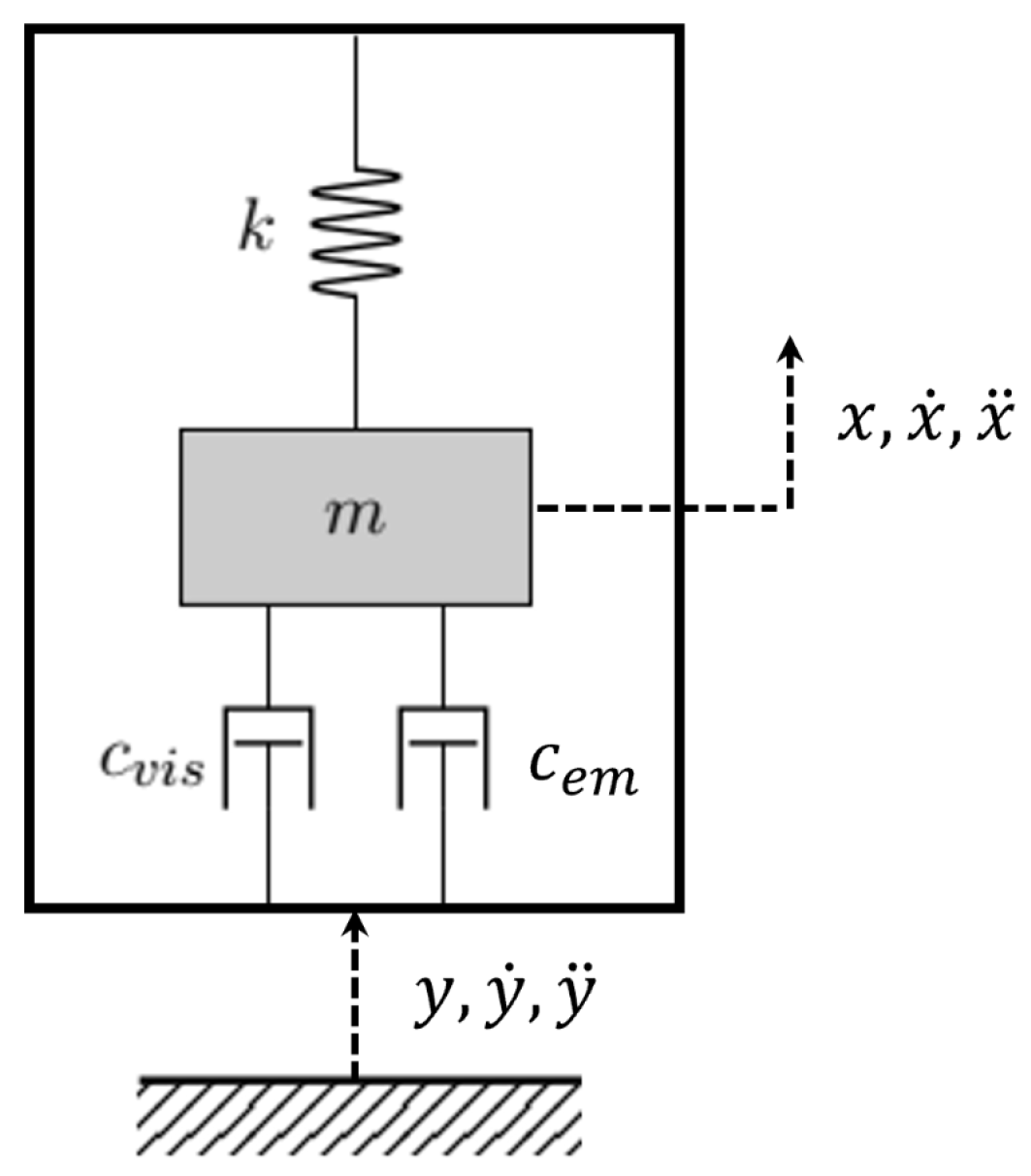
A TEMEH can be modeled as a one-degree-of-freedom (1DOF) mass–spring–damper system, schematized in Figure 3. The frame is usually shaped as a tube in which the mass oscillates [22].
y ¨ represents the external excitation coming from the ambient vibrations. The damping has two components: viscous-type friction ( c v i s ) and electromagnetic induction ( c e m ) [23]. The first one depends on the mechanical friction between the mass and the tube, whereas the second one depends on the induction of currents in the coil, which results in a damping force on the magnet.
The equation of motion governing the system’s dynamics is:
m x ¨ + c v i s + c e m x ˙ y ˙ + k x y = 0
By introducing the relative coordinate z = x y , the following expression is obtained:
m z ¨ + c v i s + c e m z ˙ + k z = m y ¨
For a linear system, the natural frequency is fixed and independent of the external excitation; this is due to the fact that the stiffness k is a constant. The mechanical power harvested is at a maximum when the excitation frequency coincides with the natural frequency.
Assuming that the system is linear and the excitation is sinusoidal with a fixed frequency, the power harvested in resonance conditions is
P r e s = m ζ e m Y 0 2 4 ω n ζ e m + ζ v i s 2
where m is the moving magnet’s mass; ζ e m and ζ v i s are the electromagnetic and viscous damping factors, respectively; Y 0 is the amplitude of the sinusoidal input; and ω n is the system’s natural frequency. The maximum power is obtained if the two damping factors are equal ζ e m = ζ v i s . The maximum harvested power increases with higher external excitation, lower resonance frequency, and lower damping factors.
If the system is linear, the power harvested decreases rapidly as the excitation frequency moves away from the natural frequency.
The energy conversion depends on the interaction between the mechanical and electromagnetic subsystems. The equivalent circuit of the TEMEH is reported in Figure 4.
The coil inductance can be neglected for frequencies less than 1 kHz [24]. If a purely resistive load is considered, the circuit equation is as follows.
V ( t ) = R l o a d + R c o i l i ( t )
The induced voltage can be computed according to Faraday–Lenz’s law:
V ( t ) = ϕ t = ϕ z z t = K e m z ˙
where K e m is the electromagnetic coupling coefficient. The electromagnetic damping force acting on the mass can be computed as
F e m = K e m i ( t ) = c e m z ˙
By substituting the expression of the current from Equation (4), the electromagnetic damping coefficient can be obtained:
c e m = K e m 2 R l o a d + R c o i l

2.2. Frequency Tuning

In the previous section, the importance of tuning the system’s natural frequency to the external excitation was highlighted. Since ambient vibrations are usually in the range of 1–100 Hz [4], the natural frequency of the harvester should be low, even ultra-low for many applications, such as onboard railway systems [25]. One way to overcome this problem is to use mechanical frequency-up converting techniques.
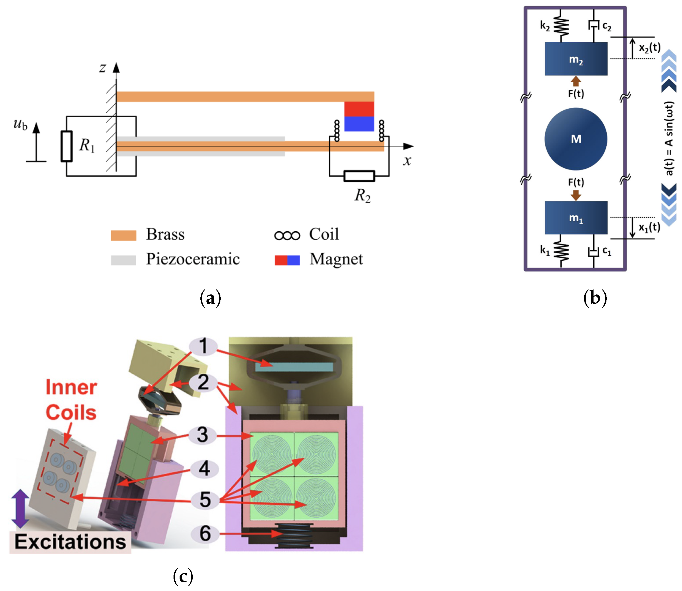
Frequency-up conversion is common in electromagnetic–piezoelectric hybrid EHs, which are usually constituted by a piezoelectric cantilever beam with a magnet on the tip [26]. The frequency-up is achieved either by motion magnification or by impact on the cantilever beam, which, as a result, vibrates at its natural frequency. An example of a frequency-up impact-based harvester is reported in [27]. When a low-frequency external excitation near the resonance of the magnetic beam is applied, the magnetic oscillator vibrates and impacts the piezoelectric beam. After the contact, the piezoelectric oscillator vibrates with its own high resonant frequency. An impact-based harvester without a cantilever beam is designed in [28]. The harvester is characterized by a non-magnetic ball that acts as a low-frequency oscillator in the middle of two high-frequency oscillators. The ball, by impacting the other two masses, couples the applied low-frequency vibration into the high-frequency spring–mass structure.
Zhongjie Li and his research group developed, over the years [29,30], an impact-based frequency-up conversion hybrid device to harvest energy from human motion [31]. The device’s frame houses a set of inner coils, an array of permanent magnets suspended by a mechanical spring, and a piezoelectric stack encompassed by a rhomboidal bridging component, which also acts as a force-amplification mechanism. While the array of magnets moves vertically under external excitation, it impacts the rod fixed on the bridging component, which converts it into tensile or compressive force acting on the piezoelectric stack. A major novelty is that the magnets are alternatively arranged in order to induce a phenomenon called abrupt flux density change, which leads to a much larger electromotive force due to the fast variation of magnetic flux. In this way, the device is able to achieve an impressive instantaneous peak power of 2.1 W.
Examples of frequency-up conversion harvesters are reported in Figure 5.

2.3. Bandwidth Expansion

The maximum harvested power in Equation (3) is valid only when the natural frequency of the system corresponds to the excitation frequency. The generated power is much lower when the system is away from the resonance point. Since ambient vibrations typically have several fundamental frequencies, a linear system can only convert a portion of the input energy. As a consequence, linear resonance-based harvesters are engaged with a problem named narrow-frequency band [12].
A review of the possible techniques to overcome this limitation and increase the system’s bandwidth is presented in [32]. The most commonly applied to TEMEHs are:
  • Non-linear suspensions;
  • Geometrical non-linearities;
  • Non-linear Energy Sinks (NESs);
  • Multi-stabilities;
  • Multi-DOF systems.
Introducing non-linear elements allows the system to provide different responses for different inputs. In this way, the harvesters can passively adapt themselves in new loading conditions [12]. Non-linearities can be introduced with non-traditional suspension systems, such as magnetic or MEMS springs, which will be discussed in detail in the next subsection.
In multi-stable systems, the moving magnet oscillates in more than one equilibrium position on the basis of the excitation frequency and amplitude. This can be achieved by placing additional fixed magnets on either side of the frame, as in [33].
A multi-DOF system can be designed by introducing two or more oscillating magnets, also in different directions. This results in a Frequency Response Function (FRF) with multiple peaks that can harvest different excitation frequencies [34]. 2DOF configurations will be addressed in Section 4.
Non-linear Energy Sinks (NESs) were initially used as vibration absorbers because they have better performance than linear ones. A targeted energy transfer (TET) from the main system to the NES can be obtained due to its lack of a preferential resonance frequency [35,36]. This can be achieved by minimizing the linear component of the stiffness. The transferred energy can then be harvested to produce electrical power. An NES coupled with an electromagnetic energy harvester is presented in [37,38]. A pair of permanent magnets acts as the mass of the NES, while the non-linear spring is formed by a thin steel beam. To minimize its linear stiffness, the beam is axially preloaded and two more permanent magnets are fixed on the primary mass. In [39], non-linear stiffness is obtained with two elastic springs and a couple of permanent magnets. An analytical model of the stiffness is derived in order to define the distance between the fixed magnets and the mass that minimizes the linear component of the stiffness. The two designs are shown in Figure 6.

2.4. Suspension Classification

The suspension of a TEMEH defines the behavior and the characteristics of the system, particularly its stiffness. For this reason, it is a crucial element for tuning the resonance frequency with the external excitation. There are three main types of suspension used in TEMEHs:
  • Mechanical spring;
  • MEMS spring;
  • Magnetic spring.
In this paper, the term spring is used to describe the element associated with the restoring force and the stiffness characteristic of the system, which is modeled with the parameter k in Equation (2). k is constant in linear systems, such as devices with traditional mechanical springs, or it is a variable with respect to the relative displacement z in non-linear systems, such as devices with MEMS or magnetic springs, as detailed below.
Traditional mechanical springs are the most common elastic element in the industry. They have a simple structure and are suited for small devices, while also providing easy installation. Moreover, they are quite cheap since they are widely available in the market, and their behavior is easily predictable, even with analytical modeling. Their main limitation is that the harvester’s response is linear with a single resonance frequency. The energy conversion and efficiency are high only in resonant conditions. In the vast majority of applications, ambient vibrations present a wide spectrum, and their energy is spread along a certain number of fundamental frequencies. As a consequence, TEMEHs with traditional springs can only harvest a small fraction of the available kinetic energy due to the limitation in their frequency bandwidth [40].
As previously discussed, a way of increasing the system’s bandwidth is adopting a non-linear spring as the suspension. This can be obtained with MEMS springs. These are usually characterized by particular geometric configurations, such as miniaturized cantilever beams or micromachined planar springs that can present multi-stabilities. However, the use of MEMS springs elevates the system’s complexity, requires higher fabrication costs and time, and can introduce issues related to mechanical fatigue [40,41]. Moreover, the resulting resonant frequencies are usually in the order of 100 Hz, higher than the normal range of ambient vibrations.
A more popular solution than MEMS springs for introducing non-linearities in the system is the design of TEMEHs with a magnetic levitation architecture. A magnetic spring is defined as a set of two or more permanent magnets with opposite polarities. The magnetic force acting between the magnets represents the restoring force of the system. The magnitude of the force, hence the spring’s stiffness, depends on the geometrical and magnetic properties of the magnets [42]. Magnetic suspensions offer a non-complex design, low maintenance requirements, and the ability to operate autonomously with stable performance for long periods of time [22]. Since there is no contact involved, there are no issues related to mechanical fatigue. Moreover, since the stiffness is lower than mechanical springs, the resonance frequencies are lower, as are the damping factors [43]. This results in higher output power, as shown in Equation (4), and brings the resonance frequencies closer to the ambient vibration frequencies.
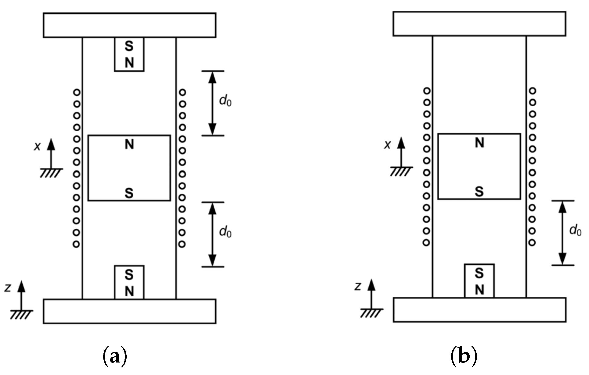
The stiffness associated with a magnetic suspension is non-linear, and thus, the system’s bandwidth is increased. The stiffness can be “hardening” or “softening”. In “hardening” springs, the stiffness increases as the displacement increases, whereas in “softening” springs, the stiffness decreases. The corresponding force–displacement curves are reported in Figure 7.
A “softening” spring is obtained with an asymmetric magnetic spring, whereas a “hardening” one is obtained with a double-sided magnetic spring. The two different types of magnetic springs are illustrated in Figure 8.
“Hardening” and “softening” behaviors result in a variation of the system’s natural frequency with different excitation amplitudes, as shown in Figure 9.
For vibrational energy harvesting applications, a “softening” spring is preferred, since with higher excitation amplitudes, the resonance frequency decreases. Moreover, the absence of the top magnet guarantees longer strokes of the moving magnet. A “hardening” effect can be observed when the excitation amplitude is particularly high and the moving magnet hits the top of the tube, as in the case of the 2DOF TEMEH with two asymmetric magnetic suspensions in series in [46]. The height of the tube must be properly designed to ensure a sufficiently long magnet stroke and to prevent detuning caused by the hardening effect.
Since the suspension types analyzed in this section all have both advantages and disadvantages, there are solutions in the literature that feature a hybrid suspension. They combine more than one of the aforementioned suspension types in order to exploit their strengths and achieve a greater energy harvesting efficiency. Since the different spring types are characterized by different ranges of stiffness, hybrid suspensions allow them to capture energy in a wider frequency range. Moreover, they can be utilized to enhance the non-linear behavior of the system, as described in Section 2.3 when analyzing Non-linear Energy Sinks (NESs). However, in general, a higher volume is required to accommodate the different springs. The architectures of devices featuring hybrid suspensions will be discussed in detail in Section 3.4.

3. 1DOF TEMEHs

In this section, different 1DOF TEMEHs from the literature with the suspension types described in Section 2.4 are reported, highlighting their main features and output parameters. In this paper, all TEMEHs that present a single resonance peak for output voltage/power are regarded as 1DOF TEMEHs.

3.1. Mechanical Spring

The harvester designed by Halim et al. [28], as described in Section 2.2 and shown in Figure 5b, utilizes a frequency-up conversion mechanism to transform the low-frequency (2–6 Hz) input from human motion into a high-frequency (about 50 Hz) oscillation of the two magnets. These magnets are fixed to the frame with mechanical helical springs. When the non-magnetic ball hits one of the two magnets, the magnet experiences a high-frequency motion with exponential decay that induces an electromotive force in the corresponding coil. The two coils are then connected in series to maximize the electrical output. Each magnet is modeled as a 1DOF system and is simulated on MATLAB and experimentally tested with a shaker and by hand motion. The mean power obtained from a hand-shaking excitation of 2.06 g at 5.17 Hz is 2.15 mW. The harvester’s overall volume is 6.47 cm3, resulting in a Normalized Power Density (NPD) of 78.47 μ Wcm 3 g 2 .
Costanzo et al. [47] designed a TEMEH with a helical spring and a double coil structure. Compared to the traditional architecture, which uses a moving magnet and a single fixed coil, an additional coil is added and electromagnetically coupled with the magnet. The second coil is in relative motion with respect to both the magnet and the fixed coil. The objective is to compare the double coil configuration to a standard single coil one. The result is that power is more than tripled when the system is far away from resonance conditions. At 80% of the resonance frequency (98.5 Hz) the harvester generates 7.22 mW with 2 g amplitude of excitation. The overall volume is not stated, so the NPD cannot be computed.
Ordoñez et al. [48] designed a high-performance TEMEH with a “Magnet in-line coil” structure, shown in Figure 10b. The moving mass is composed of three ring magnets arranged in a cylindrical Halbach array configuration. Cylindrical Halbach arrays consist of magnets polarized axially and radially in an alternating way in order to enhance the magnetic flux in the interior part [49]. A single cylindrical coil is placed inside the array. This configuration helps minimize the device’s volume. The magnet array is connected to the structure with two helical springs. The prototype was optimized through FEM software numerical analysis to maximize the peak power. The final configuration presents a volume of 137.9 cm3. Under external excitation of 0.03 g at resonance frequency 61.7 Hz, the device is able to produce an open-circuit RMS AC voltage of 6.65 V and an output power of 3.61 mW, achieving an impressive NPD of 29.08 mWcm−3g−2. Its main limitation is that, since the stiffness of the helical springs is linear, the system has a narrow bandwidth, causing the output power to rapidly decrease away from the resonance.
Inspired by the work of Ordoñez et al. [50], Phan et al. [51] investigated four different configurations of TEMEHs with cylindrical Halbach arrays. These configurations feature varying numbers of coils and magnets, as well as different magnet arrangements. A fully automatic optimization procedure is implemented to maximize the power output of each configuration. The calculation of the power output is articulated in two steps: first the evaluation of the electromagnetic coupling factor and then the solution of the differential equations for the mechanical and electrical subsystems. The first step is achieved with the FEM software Ansys Maxwell, while the second is performed in MATLAB/Simulink. The input parameters for the optimization are provided to a Python script, which manages the co-simulation between the two software programs in order to automate the process. The configuration with three magnets and one coil proved to be the best one, as all the other configurations converged to it during the optimization process. At 55 Hz with an external excitation of 0.2 g, an output power of 28.3 mW was obtained. The total volume of the device is 30 cm3 and its NPD is 23.6 mWcm−3g−2.
Li et al. [52] studied multiple configurations of a TEMEH with an array of rectangular magnets and an array of coils. The magnets are arranged in alternating polarity and are fixed to the structure with two helical springs. Keeping the overall volume of the device fixed at 34.8 cm3, the number of magnets and coils was varied from 3 to 12. The optimal configuration was obtained when the number was set to 6. The harvester generates a power output of 3.71 mW at the resonance frequency of 41.2 Hz with an amplitude of 1 g, achieving an NPD of 106.68 μ Wcm−3g−2. However, the peak open-circuit voltage is only about 650 mV, a small value that complicates the integration with commonly used energy-harvesting power management integrated circuits (PMICs).
Shen et al. [53] designed a micro-TEMEH with a volume of only 1.6 cm3. The moving mass is represented by a coil and its holder, which are attached to the vibration source via a mechanical helical spring. Two magnets of the same polarity, facing each other, are fixed inside an iron frame to enhance the magnetic flux linkage. When excited at the resonance frequency of 10.1 Hz with an amplitude of 0.52 g, the harvester produces an RMS AC power of 0.72 mW, achieving a remarkable NPD of 1.66 mWcm−3g−2. However, the RMS AC voltage in resonance conditions is about 70 mW, a value that implies compatibility issues with the PMIC.
The structures of the presented TEMEHs using mechanical springs are reported in Figure 10.
Figure 10. TEMEHs with mechanical springs: (a) Costanzo et al. [47]; (b) Ordoñez et al. [48]; (c) Li et al. [52]; (d) Shen et al. [53].
Energies 18 01588 g010

3.2. MEMS Spring

The introduction of MEMS springs with non-linear behavior can help overcome the narrow-bandwidth limitation of harvesters with mechanical springs.
Lei et al. [54] designed a micro TEMEH with a MEMS planar copper spring, manufactured using laser cutting. An S-type folded beam structure was adopted to achieve a lower resonance frequency. The total size of the spring is 9 × 9 mm2. At its center, a rectangular permanent magnet is fixed, which moves relative to a wire-wound coil under external excitation. The spring was studied with FEM in Ansys to properly tune the resonance frequency. The overall volume of the device is 1.8 cm3 and the weight of the magnet is 0.42 g. The maximum output power is 205 μ W at the resonance frequency of 124 Hz with an excitation amplitude of 0.5 g, achieving an NPD of 0.47 mWcm−3g−2.
Roy et al. [55] proposed a Duffing oscillator-based non-linear TEMEH with cubic stiffness. The non-linear behavior is achieved using a laser-micromachined MEMS spring, fabricated on a 300 μ m thick FR4 substrate. Two repulsive NdFeB magnets are placed on the substrate with two soft magnetic iron blocks fixed on their outer sides to concentrate the magnetic flux onto the coil. Two prototypes are produced in order to test monostable and bistable configurations. Bistability is achieved by introducing a repulsive magnetic force at the tip of the beam. In the monostable configuration, there is only one equilibrium position, whereas in the bistable one, there are two potential wells separated by a potential barrier, providing two equilibrium positions. An FEM analysis in COMSOL multiphysics showed that the linear stiffness of the bistable configuration is lower, resulting in a lower resonance frequency and an overall shift in the frequency response toward the low-frequency region. The bistable configuration generates a lower power output due to a strong bistable force, which introduces additional damping. The monostable configuration produces 1.18 mW under external excitation of 1 g at a resonance frequency of 63.7 Hz, whereas the bistable one generates 0.72 mW under 1 g at a 39 Hz resonant excitation. The volume of the device is non-explicitly stated, but it is computed from the reported power density values. A volume of 5.9 cm3 is obtained for both configurations. The NPDs are, respectively, 0.20 and 0.12 mWcm−3g−2.
Wang et al. [56] developed a fully integrated MEMS TEMEH that features a highly efficient solenoid with a soft magnetic circuit to enhance the power density. The solenoid is produced by surface microfabrication technology, achieving 300 wire turns. The moving mass consists of a magnetic pair suspended by four clamped-guided springs, which demonstrate a non-linear “hardening” behavior for wideband energy collection. The presence of the Ni-based soft magnetic circuit increases the flux density inside the microsolenoid, resulting in a higher electromechanical coupling. An output voltage three times larger is obtained compared to an air-cored structure with the same number of turns. The overall size is just 0.045 cm3. At a resonance frequency of 138 Hz, under external excitation of 1 g, the harvester generates 0.265 mW, achieving an impressive NPD of 5.89 mWcm−3g−2.
Nicolini et al. [57] designed a TEMEH with two stacked orthoplanar springs produced by additive manufacturing. The springs are fixed to a circular rigid frame, which also contains the coil. The moving mass is represented by an array of annular NdFeB magnets mounted on a vertical center pivot, which is fixed to the two springs. The unique geometry of the springs, shown in Figure 11b, results in high compliance and a compact radial size. The total volume of the device is 173 cm3. An FEM analysis was conducted to compute the springs’ maximum displacement and the stresses during the oscillation. Fast Fourier Transform (FFT) analysis revealed two peaks at 15 and 30 Hz, highlighting the extended bandwidth due to the springs’ non-linearities. The device generates 5 mW at 15.1 Hz under an excitation amplitude of 0.37 g, reaching an NPD of 0.21 mWcm−3g−2.
The structures of the presented TEMEHs using MEMS springs are reported in Figure 11.

3.3. Magnetic Spring

Magnetic springs also produce non-linear behavior in the harvester. However, unlike MEMS ones, they do not experience issues related to mechanical fatigue and their design and characterization is simpler. The main challenge is limiting the overall volume of the device while preserving sufficient output power.
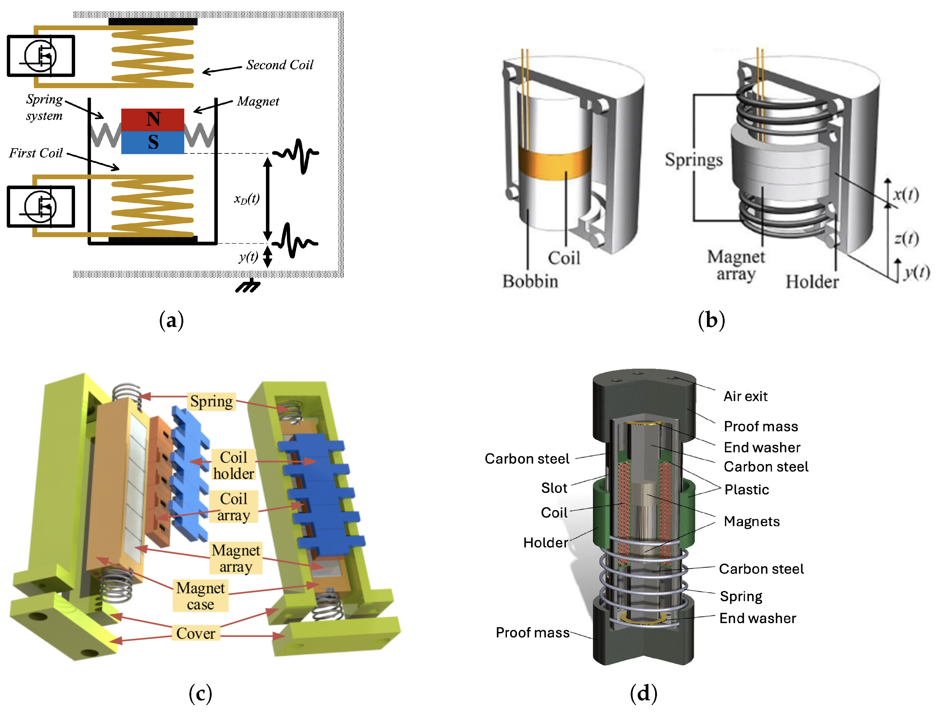
Lo Monaco et al. [58,59] developed a 1DOF TEMEH with an asymmetric magnetic spring. This device is the result of an extensive design and optimization process carried out by Aurelio Soma’s research group at Politecnico di Torino, starting from the harvester described in [44]. The research group also holds some patents in the energy harvesting field [60,61]. The moving magnet oscillates inside a tube with an internal guide, which is necessary to counteract radial force contributions that tilt the moving magnet and generate unwanted additional motions. The harvester is modeled as a mass–spring–damper system. Design optimization was carried out using the FEM software Ansys Maxwell to properly identify the harvester’s key parameters, such as stiffness and damping. The dynamic behavior was then simulated in MATLAB/Simulink. Detailed modeling allowed the authors to investigate the influence of design parameters on output power. A new optimized harvester was designed, and experimental tests were performed on a prototype, as detailed in Lo Monaco’s PhD thesis [62]. The experimental FRFs show a non-linear “softening” behavior, typical of asymmetric magnetic springs. The maximum output power in resonance conditions (4 Hz) with an excitation amplitude of 0.5 g is 39 mW. The harvester’s volume is 61.5 cm3, and the resulting NPD is 2.54 mWcm−3g−2.
Nico et al. [63] designed a C-battery-scale velocity-amplified TEMEH with two sets of magnetic suspensions. The velocity increase is achieved through the impact of a secondary lighter mass oscillating inside the primary mass. This resulted in an increase in the output electrical parameters, as shown in Equation (5). The primary mass consists of seven coils and oscillates within a double-sided magnetic suspension. The secondary mass is made up of a Halbach stack of five magnets and is suspended by a weaker magnetic spring inside the primary mass. Through COMSOL simulations, the influence of the cap height is analyzed. A larger cap height allows the primary mass to move more freely with less effect of the magnetic forces, resulting in a lower natural frequency. Additionally, the impact of the coil turns on the device’s volume and power output is investigated. Experimental tests were performed on a prototype. Under an external excitation of 0.4 g, at the resonance frequency of 11.5 Hz, the device generates 2.06 mW. The overall volume is 8.12 cm3, resulting in an NPD of 1.59 mWcm−3g−2.
Royo-Silvestre et al. [64] designed a TEMEH with an asymmetric magnetic spring for ultra-low-frequency applications (<2 Hz). Both magnets present a block shape, but the fixed one is 10 times larger to achieve a very low resonance frequency. However, this results in a very high equilibrium position for the moving magnet, which requires a long tube for oscillation (272 mm) and leads to a large volume (938 cm3). At the resonance frequency of 1.7 Hz, with an excitation amplitude of 0.5 g, the harvester generates a 1.33 RMS AC open-circuit voltage and an RMS AC power of 4.38 mW. The resulting NPD is just 18.7 μ Wcm−3g−2, due to the high volume.
Salauddin et al. [65] developed a low-frequency TEMEH with a dual Halbach array of rectangular magnets. The suspension system consists of a double-sided magnetic spring, with two magnets placed on the moving mass and two more fixed on the frame. Three coils connected in series are placed between the two arrays. The double Halbach array allows to the maximization of the flux linkage with the coils. The prototype was optimized using FEM analysis to evaluate the magnetic field and select the coils’ parameters. As already discussed in Section 2.4, the double-sided magnetic spring results in a “hardening” non-linear stiffness, which increases linear resonance frequencies under larger excitation amplitudes. The harvester generates a RMS power of 1.1 mW at a resonance frequency of 11 Hz and under an external excitation of 0.5 g. Since the overall volume is 32.76 cm3, the resulting NPD is 0.13 mWcm−3g−2.
Su et al. [66] proposed a TEMEH with a unique asymmetric magnetic spring. While most magnetic springs feature a repulsive magnet fixed to the bottom of the frame, as shown in Figure 8b, this device is characterized by a magnet fixed on the top of the frame, which exerts an attractive force on the moving magnet. Two pyrolytic graphite sheets also exert a diamagnetic force on the magnet. A coil is electroplated onto each graphite sheet for electromotive force induction due to the magnet’s oscillation. The forces resulting from the magnetic interaction are computed using the FEM software COMSOL and experimentally validated. Under external excitation at a resonance frequency of 5 Hz and a displacement amplitude of 0.8 mm, the harvester generates an output voltage of 1.64 mW and an output power of 0.076 μ W for a single coil with 80 turns. Since the device’s volume is not known, the NPD cannot be computed.
The structures of the presented TEMEHs using magnetic springs are reported in Figure 12.

3.4. Hybrid Suspensions

Hybrid solutions featuring more than one suspension type have also been studied in the literature.
Costantinou et al. [67] developed a 3D-printed TEMEH that exploits in-plane motions. It features a MEMS spring constituted by two ABS beams. The MEMS spring is a leaf isosceles trapezoidal flexural (LITF) pivot, a type of complex flexure suited for in-plane motion. The LITF topology restricts out-of-plane modes to higher frequencies, allowing for the exploitation of in-plane motions. Additionally, it can be fabricated monolithically, making 3D printing an ideal manufacturing process. A support platform is attached to the tip of the spring, on which two permanent magnets are fixed. Two opposing magnets are placed on the frame to add a magnetic contribution to the restoring force. In this way, the suspension’s stiffness has a linear component related to the mechanical stiffness of the pivot and a non-linear component related to the magnetic interaction. Between the two pairs of magnets, two coils are placed and fixed to the frame. The system is modeled using the FEM software COMSOL to derive the non-linear stiffness and the electromagnetic coupling coefficient. A “softening” effect is observed, along with an increased bandwidth around the resonance frequency of 147 Hz. At resonance, under an external excitation of 1 g, the device generates 2.9 mW. Since the volume is only 6 cm3 thanks to the MEMS spring miniaturization, the resulting NPD is 0.48 mWcm−3g−2.
Aldawood et al. [68] designed a uniquely enhanced, magnetic-spring-based TEMEH and compared it to a traditional one with the same size, dimensions, coil turns, and magnets. Both devices feature a double-sided magnetic spring and a moving mass consisting of a levitating magnet. However, in the new design, the top magnet of the suspension is fixed to an FR4 planar spring, allowing an additional degree of freedom. Moreover, an extra coil is placed on the upper part of the frame in order to harvest energy from the motion of the top magnet. The total volume of the device is 222 cm3. An analytical model and an FEM model in COMSOL were developed to derive the non-linear restoring force on both the middle and the top magnets, as well as the output voltage of the harvester. Experimental tests were conducted on a series of prototypes and a good agreement between numerical and experimental results was revealed. The Frequency Response Function (FRF) showed a “hardening” effect due to the double-sided magnetic spring, shifting the resonance peak toward higher frequencies. Moreover, the non-linear behavior increases the system’s bandwidth with growing external excitations. The superiority of the new design over the traditional one is evident. This is likely due to the freeing of the top magnet, which allows the middle magnet to move with higher speeds and fewer constraints, since the additional coil’s power output is low. With a 0.4 g base excitation at 9 Hz, the traditional harvester achieved an NPD of 0.5 mWcm−3g−2, whereas the new design with the same excitation amplitude at its resonance frequency of 11 Hz achieved a solid NPD of 1.97 mWcm−3g−2.
Fan et al. [69] developed a TEMEH characterized by a double-sided attractive magnetic spring. Two magnets are fixed at the two ends of a tube, with their polarity arranged to exert an attractive force on both sides of the center magnet. If the gap between the magnets is too small, they will snap together, causing the harvester to stop working. For this reason, two mechanical springs are employed to support the center magnet. Additionally, a pair of stoppers is placed between the magnets to limit the central magnet’s movement to a range where the elastic force is greater than the magnetic force. The magnetic suspension exhibits a non-linear “softening” behavior, allowing the device to capture ultra-low frequencies at high excitation amplitudes. Under an external excitation of 0.8 g at the harvester’s resonance frequency of 9 Hz, the generated output power is 1.15 mW. The device’s volume is only 12 cm3, and its NPD is 0.15 mWcm−3g−2.
The structures of the presented TEMEHs with hybrid suspensions are reported in Figure 13.

4. 2DOF TEMEHs

As previously stated in Section 2.3, adopting a TEMEH with a multi-DOF configuration is one of the main strategies to increase the system’s bandwidth. A multi-DOF system presents multiple peaks at different frequencies, allowing it to harvest more energy from the environment.
A popular solution is to adopt a 2DOF configuration. It is particularly beneficial when the system operates under two different conditions, each associated with distinct excitations and fundamental frequencies. This is the case in onboard railway monitoring applications, where the fundamental vibration frequencies change depending on whether the body is loaded or in tare conditions. Unlike 1DOF TEMEHs, 2DOF configurations exhibit two distinct resonance peaks for output voltage/power. In this section, different 2DOF TEMEHs from the literature are reported.

4.1. Mechanical Spring

Ung et al. [70] developed a 2DOF TEMEH to harvest energy from freight car vibrations in load/tare conditions. The first mass consists of four permanent magnets separated by mild steel spacers and a magnetic shield to prevent the surrounding materials from affecting the motion. The second mass is made up of three separate coils wrapped around a polycarbonate spool. Two mechanical springs form the suspension system. The two resonance frequencies are tuned to acceleration Power Spectral Density (PSD) values obtained from experimental measurements of vertical vibrations in freight cars, both in loaded and unloaded conditions. Under a sinusoidal excitation of 0.5 g amplitude, the device is able to generate an output power of 350 mW at the dominant frequency (6.0 Hz) in the loaded condition and 230 mW at the dominant frequency (14.6 Hz) in the unloaded condition. The device’s volume is not explicitly stated, so it was estimated to be around 600 cm3 based on the magnet data. The resulting NPD is 2.33 mWcm−3g−2.
Feng et al. [34] propose a dual-resonance TEMEH aimed at overcoming the main limitation of conventional dual-resonance harvesters: the significant separation between the two resonance peaks. This results in a low harvested power between them. For this reason, the authors designed a TEMEH with dual uncoupled resonance frequencies, featuring two planar springs and two oscillating masses. The springs consist of multiple serpentine sectors, allowing for lower stiffness and reduced occupied area and are attached to the frame. The first mass is a permanent magnet, while the second one is a non-magnetic copper mass. The device increases the useful bandwidth by more than twice compared to an equivalent single-resonance harvester. At the first natural frequency of 58 Hz, under an external excitation of 0.27 g, the harvester generates 10.9 mW. The device’s volume is 53.9 cm3 and the resulting NPD is 2.77 mWcm−3g−2.

4.2. MEMS Spring

Masood Ahmad et al. [71] designed a 2DOF TEMEH with a conventional cantilever beam configuration for low-frequency applications. It comprises two distinct beams, each with a magnet at one end. The first beam is split into two halves in order to allow the oscillation of the second beam between them. This reduces the system’s volume without shortening the beam length, which would increase the system’s natural frequencies. The first beam is attached to an adjustable L-shaped frame, which also carries two adjustable coil holders. This design allows it to obtain the desired gap fit between the magnet and the coil holder’s base. The harvester has two distinct resonant frequencies, which depend on the first modes of the two beams. The authors developed an analytical model to study the dynamic behavior and a COMSOL model to identify the system’s modes. Experimental tests were conducted to determine the power generated by the harvester. Under an external excitation of 0.09 g acceleration and at the first resonance of 4.4 Hz, the two coils generated 2.34 mW and 0.17 mW, respectively, leading to a total of 2.51 mW. At the second resonance frequency of 5.5 Hz, with the same excitation amplitude, the coils generated 0.9 mW and 9.8 mW, respectively, leading to a total of 10.7 mW. Since the overall volume was 333 cm3, the NPD at the second resonance frequency was 3.97 mWcm−3g−2.
Tao et al. [72] developed a 2DOF TEMEH with two different MEMS springs and two masses to increase the system’s bandwidth. The primary mass, which also acts as the coil, is suspended by three sets of spiral-beam springs, whereas the accessory mass is suspended by an inner circular spring. The accessory mass is used to tune the system’s natural frequencies. All the masses and springs are micromachined to achieve an overall volume of just 0.29 cm3. A cylindrical magnet is bonded to an acrylic plate and placed above the center of the device. The system presents non-linear behavior and two distinct resonance peaks at 326 and 391 Hz. It produces a power of 0.96 nW under an external excitation of 1.2 m/s2 at the second resonance frequency. The resulting NPD is 0.22 μ mWcm−3g−2.

4.3. Magnetic Spring

Lo Monaco et al. [46,73] designed a 2DOF TEMEH that features two magnetic suspensions in series with an asymmetric configuration. A magnet is fixed to the bottom of the frame, and two more magnets serve as the moving masses. An analytical 2DOF model is developed to determine the system’s equations and then also a numerical one on Ansys Maxwell. The numerical model is used to compute the forces acting between the magnets and the electromagnetic coupling coefficient. Ten coils are placed on the frame to identify the optimal number of coils and the positions that guarantee the highest power output. Simulations show that the first mass oscillates around the high-induction zone near coil three, while the second mass oscillates around the high-induction zone near coil ten. These two coils are selected and then connected in series to sum their contributions. The dynamic behavior is simulated in MATLAB/Simulink, and the results are compared to experimental tests conducted on a prototype. The comparison shows a strong agreement between experimental and numerical FRFs. The first resonance frequency is related to the upper moving magnet, while the second is related to the lower moving magnet, which is subjected to a “hardening” effect from the interaction with the upper moving magnet. At the first resonance frequency of 3.4 Hz, under an external excitation of 0.4 g, the harvester generates 8.25 mW. Since the device’s volume is 226 cm3, the resulting NPD is 0.23 mWcm−3g−2.
Fan et al. [74] proposed a non-linear 2DOF TEMEH with two double-sided magnetic suspensions to capture ultra-low-frequency excitations. The device is created by encapsulating in a cylindrical housing a 1DOF TEMEH with a double-sided magnetic spring and a single coil. At both ends of the tube, two additional permanent magnets are placed and two more coils are added to exploit the additional relative motions of the 2DOF configuration. The objective is to compare the 2DOF harvester with the original 1DOF version. The 2DOF harvester demonstrates a 152% wider bandwidth and a higher power output. Under an external excitation of 0.5 g, it generates 2.58 mW at the first resonance frequency of 7.5 Hz and 1.09 mW at the second resonance frequency of 18.5 Hz. The peak power of 2.58 mW is significantly greater than the 1.86 mW produced by the 1DOF configuration. The device’s volume is 26.3 cm3, and the resulting NPD is 0.39 mWcm−3g−2.
The structures of the presented 2DOF TEMEHs are reported in Figure 14.

5. Discussion

This section provides a final comparison between the TEMEHs analyzed in the paper. A summary of the main parameters (suspension type, volume, resonance frequency, excitation amplitude and AC RMS power) is reported in Table 2 and Table 3 for the 1DOF and 2DOF TEMEHs, respectively.
The performance comparison of the harvesters is based on two indexes: Normalized Power Density (NPD) and Volumetric Figure of Merit (FoMv). NPD is defined as the ratio of the output RMS AC power (mW) to the device volume (cm3) multiplied by the squared acceleration amplitude (g2) [75]:
N P D = P A C , R M S V o l A c c 2
FoMv is defined as the ratio of the real output RMS AC power to the ideal power generated by an “equivalent device of cubic geometry, having the same total package volume but with a proof mass, with the density of gold, occupying half this volume, and space for displacement occupying the other half” [76]. This index is used to compare the performance of different harvester configurations based on their overall size. The resulting expression is
F o M v = P A C , R M S 1 16 ω n ρ a u V o l 4 3 A c c
Since the resonance frequency ω n is at the denominator, the index is higher for lower frequencies. In this way, devices that focus on low-frequency harvesting are highlighted.
Some general considerations regarding 1DOF TEMEHs in relation to their suspension type can be derived from Table 2.
Mechanical spring TEMEHs can produce a high output power and present relatively good NPDs and FoMv. In some cases [48,51], the NPD is exceptionally high. However, since the harvester exhibits linear behavior due to the mechanical suspension, the output power quickly decreases away from resonance, resulting in a narrow bandwidth that is not well suited for harvesting ambient vibrations. Moreover, since the spring’s stiffness is high, the resonance frequency is high and not compatible with the normal frequency range of ambient vibrations. An exception is represented by [53], in which the implementation of a low-stiffness spring is allowed to reduce the system’s natural frequency. This, along with the low volume, allowed the authors to achieve a very high FoMv, which indicates a good conversion efficiency at low frequencies. These considerations regarding mechanical spring harvesters show that, when evaluating performance, the NPD value should be critically analyzed and correlated with other factors, particularly bandwidth and natural frequency.
In MEMS spring TEMEHs, the harvester’s bandwidth is extended compared to mechanical spring ones due to the geometric non-linearities of the suspension system. They are highly suitable for volume miniaturization and micro-harvesting applications. However, output voltage and power are low due to the limitation in the MEMS scale [54]. Moreover, they exhibit high natural frequencies. This results in relatively low NPDs and FoMv. The only exception is [56], in which the presence of a soft magnetic circuit and a microsolenoid as the coil highly improves the electromechanical coupling. In this way, this harvester achieves an impressive FoMv of 16.12%, the highest among the analyzed devices. However, a natural frequency of 138 Hz is quite high for harvesting ambient vibrations.
Magnetic spring TEMEHs allow them to obtain a very low natural frequency due to the low stiffness of the magnetic suspension. Their non-linear behavior increases the system’s bandwidth showing “softening” or “hardening” effects. They exhibit high NPDs and FoMv because of their ability to produce a considerable amount of power at low frequencies. Ultra-low resonance frequencies can be achieved, as in [64]. However, the longer magnet’s strokes required cause an inevitable increase in the overall volume, reducing the harvester’s NPD. The challenge of miniaturization can be surpassed through smart configurations and an accurate analysis of the key design parameters. In [59], the advantages of an asymmetric magnetic suspension are fully exploited to achieve an ultra-low resonance frequency with a high power output while maintaining a relatively low volume. This results in a very high NPD and FoMv. An incredibly compact design that achieves high values of NPD and FoMv is the one in [63] due to its innovative architecture and its velocity amplification mechanism.
Hybrid configurations were also discussed in the paper. When the main suspension component is a MEMS spring, the issue of the high resonance frequency is still relevant, as in [67]. The greatest results were obtained with a hybrid mechanical–magnetic suspension. The insertion of a mechanical component in a traditional magnetic suspension can be particularly beneficial, as in [68], where a fixed magnet is freed and the motion of the main oscillator is improved. This allows it to achieve the maximum power output out of the analyzed 1DOF devices. However, it also causes an inevitable increase in the overall volume.
The same considerations on the suspension types are also generally valid for 2DOF TEMEHs. The main parameters of the 2DOF TEMEHs are listed in Table 3.
With regard to mechanical springs, two harvesters [70,71] are able to achieve low resonance frequencies at the cost of a higher volume. The device in [70] is able to produce the highest output power out of all the analyzed devices. However, its NPD is lower due to its high volume. Ultra-low resonance frequencies are achieved in [71] with a smaller volume, resulting in a greater NPD. The presence of two resonance peaks greatly increases the bandwidth with respect to 1DOF mechanical spring TEMEHs.
Magnetic suspension 2DOF TEMEHs are able to combine the benefits of the non-linear stiffness and the multi-DOF configuration to achieve a wide bandwidth. However, the degree of complexity increases, and modeling the non-linear behavior becomes more challenging with respect to 1DOF solutions. Moreover, a higher overall volume is required.
In [46], a direct comparison between a 1DOF and a 2DOF solution with the same architecture is contained. The presence of two asymmetric magnetic suspensions in series in the 2DOF configuration significantly increases the height of the tube, as the upper moving magnet needs a large stroke to generate considerable power. The peak power of the 2DOF device is 13% smaller, but the bandwidth is increased by 11%. This leads to an NPD of 0.23 mWcm−3g−2 compared to the 2.54 mWcm−3g−2 of the 1DOF design.
The same comparison is performed in [74]. In this case, the 2DOF TEMEH significantly outperforms the 1DOF configuration, with a 152% wider bandwidth and a 39% increase in peak power.
By comparing Table 2 and Table 3, some general considerations on 1DOF and 2DOF designs can be made. 2DOF designs present lower values of NPDs and FoMv, mainly due to the higher volume needed to accommodate the two moving masses. Since the NPD is computed under an external sinusoidal excitation at resonance, the two tables do not take into consideration the bandwidth, which is higher in 2DOF devices. The effect of the extended bandwidth would be more evident if the harvesters were tested under real excitations coming from ambient vibrations, which present multiple fundamental frequencies. Moreover, the fact that the 2DOF designs were optimized to harvest energy in two different working conditions of the machine or the vehicle is not highlighted.

6. Conclusions

The aim of this paper is to review TEMEHs from the literature developed in the last few years. After briefly describing the working principle and the basic equations, frequency tuning methodologies are analyzed, such as frequency-up conversion. The most common methods for expanding the system’s bandwidth are also described, with a particular emphasis on the implementation of Non-linear Energy Sinks.
An original aspect of the paper is that a classification based on the suspension type is carried out to investigate the most suitable option for low-frequency harvesting. Magnetic springs provide a simple and reliable structure that eliminates the durability issues associated with MEMS springs. They also overcome the two main limitations of mechanical springs, high natural frequencies and narrow bandwidth, thanks to their lower stiffness and non-linear behavior. This makes TEMEHs with magnetic levitation architectures the most suitable for low-frequency vibration harvesting.
The main challenge is miniaturization because of the long strokes required to have low enough frequencies. Smart designs allow the minimization of the volume while still producing a good output power, resulting in high power densities. However, further research is required to produce small devices that can supply enough energy in a wide frequency range.
Another original aspect of this paper is a comparison between 1DOF and 2DOF TEMEHs designs. 2DOF TEMEHs present the ability to extend the system’s bandwidth. However, the peak power can decrease with respect to the corresponding 1DOF alternative due to the added damping of the second magnet. Moreover, the 2DOF configurations require a higher volume. Further research is needed to fully comprehend the advantages and disadvantages of multi-DOF configurations.
TEMEHs show great promise for powering Autonomous Internet of Things (AIoT) devices that require minimum maintenance and can be installed in hard-to-reach areas. With further developments, they could become a viable and greener alternative to batteries in many applications.

Author Contributions

Conceptualization, A.S., M.L.M. and M.V.P.; methodology, M.L.M. and M.V.P.; validation, M.L.M. and M.V.P.; formal analysis, M.V.P.; investigation, M.L.M. and M.V.P.; resources, A.S.; data curation, M.V.P.; writing—original draft preparation, M.V.P.; writing—review and editing, M.V.P. and M.L.M.; visualization, M.V.P.; supervision, A.S.; project administration, A.S.; funding acquisition, A.S. All authors have read and agreed to the published version of the manuscript.

Funding

This research received no external funding.

Institutional Review Board Statement

Not applicable.

Informed Consent Statement

Not applicable.

Data Availability Statement

Not applicable.

Conflicts of Interest

The authors declare no conflicts of interest.

Abbreviations

The following abbreviations are used in this manuscript:
IoTInternet of Things
WSNWireless Sensor Node
EHEnergy Harvester
EMEHElectromagnetic Energy Harvester
TEMEHTranslational Electromagnetic Energy Harvester
DOFDegree of freedom
NPDNormalized Power Density
FoMvVolumetric Figure of Merit
FEMFinite Elements Method
PMICPower Management Integrated Circuit

References

  1. Sohraby, K.; Minoli, D.; Znati, T. Wireless Sensor Networks: Technology, Protocols, and Applications; John Wiley & Sons: Hoboken, NJ, USA, 2007; pp. 1–307. [Google Scholar]
  2. Hodge, V.J.; O’Keefe, S.; Weeks, M.; Moulds, A. Wireless sensor networks for condition monitoring in the railway industry: A survey. IEEE Trans. Intell. Transp. Syst. 2014, 16, 1088–1106. [Google Scholar] [CrossRef]
  3. Taylor, P. Global Number of Connected Devices 2015–2029, by Device. 2024. Available online: https://www.statista.com/statistics/512650/worldwide-connected-devices-amount/ (accessed on 2 February 2025).
  4. Muscat, A.; Bhattacharya, S.; Zhu, Y. Electromagnetic vibrational energy harvesters: A review. Sensors 2022, 22, 5555. [Google Scholar] [CrossRef]
  5. Beeby, S.P.; Cao, Z.; Almussallam, A. 11—Kinetic, Thermoelectric and Solar Energy Harvesting Technologies for Smart Textiles; Woodhead Publishing: Hamilton, UK, 2013; pp. 306–328. [Google Scholar]
  6. Kathiriya, H.; Pandya, A.; Dubay, V.; Bavarva, A. State of art: Energy efficient protocols for self-powered wireless sensor network in IIoT to support industry 4.0. In Proceedings of the 2020 8th International Conference on Reliability, Infocom Technologies and Optimization (Trends and Future Directions) (ICRITO), Noida, India, 4–5 June 2020; pp. 1311–1314. [Google Scholar]
  7. Harb, A. Energy harvesting: State-of-the-art. Renew. Energy 2011, 36, 2641–2654. [Google Scholar] [CrossRef]
  8. Choudhary, P.; Bhargava, L.; Singh, V.; Choudhary, M.; Kumar Suhag, A. A survey—Energy harvesting sources and techniques for internet of things devices. Mater. Today Proc. 2020, 30, 52–56. [Google Scholar]
  9. Singh, J.; Kaur, R.; Singh, D. Energy harvesting in wireless sensor networks: A taxonomic survey. Int. J. Energy Res. 2021, 45, 118–140. [Google Scholar]
  10. Sherazi, H.H.R.; Zorbas, D.; O’Flynn, B. A comprehensive survey on RF energy harvesting: Applications and performance determinants. Sensors 2022, 22, 2990. [Google Scholar] [CrossRef]
  11. Aljadiri, R.T.; Taha, L.Y.; Ivey, P. Electrostatic energy harvesting systems: A better understanding of their sustainability. J. Clean Energy Technol. 2017, 5, 409–416. [Google Scholar]
  12. Hosseinkhani, A.; Younesian, D.; Eghbali, P.; Moayedizadeh, A.; Fassih, A. Sound and vibration energy harvesting for railway applications: A review on linear and nonlinear techniques. Energy Rep. 2021, 7, 852–874. [Google Scholar]
  13. Castagnetti, D. Wideband fractal-inspired piezoelectric energy harvesters. Proc. Inst. Mech. Eng. Part L J. Mater. Des. Appl. 2021, 235, 2614–2626. [Google Scholar] [CrossRef]
  14. De Pasquale, G.; Somà, A.; Fraccarollo, F. Piezoelectric energy harvesting for autonomous sensors network on safety-improved railway vehicles. Proc. Inst. Mech. Eng. Part C J. Mech. Eng. Sci. 2012, 226, 1107–1117. [Google Scholar]
  15. De Pasquale, G.; Somà, A.; Fraccarollo, F. Comparison between piezoelectric and magnetic strategies for wearable energy harvesting. J. Phys. Conf. Ser. 2013, 476, 012097. [Google Scholar] [CrossRef]
  16. Munaz, A.; Lee, B.C.; Chung, G.S. A study of an electromagnetic energy harvester using multi-pole magnet. Sens. Actuators A Phys. 2013, 201, 134–140. [Google Scholar] [CrossRef]
  17. de Araujo, M.V.V.; Nicoletti, R. Electromagnetic harvester for lateral vibration in rotating machines. Mech. Syst. Signal Process. 2015, 52, 685–699. [Google Scholar]
  18. Fu, H.; Mei, X.; Yurchenko, D.; Zhou, S.; Theodossiades, S.; Nakano, K.; Yeatman, E.M. Rotational energy harvesting for self-powered sensing. Joule 2021, 5, 1074–1118. [Google Scholar] [CrossRef]
  19. Castagnetti, D. A simply tunable electromagnetic pendulum energy harvester. Meccanica 2019, 54, 749–760. [Google Scholar]
  20. Chen, J.; Bao, B.; Liu, J.; Wu, Y.; Wang, Q. Pendulum energy harvesters: A review. Energies 2022, 15, 8674. [Google Scholar] [CrossRef]
  21. Gao, M.; Cong, J.; Xiao, J.; He, Q.; Li, S.; Wang, Y.; Yao, Y.; Chen, R.; Wang, P. Dynamic modeling and experimental investigation of self-powered sensor nodes for freight rail transport. Appl. Energy 2020, 257, 113969. [Google Scholar]
  22. Carneiro, P.; dos Santos, M.P.S.; Rodrigues, A.; Ferreira, J.A.; Simões, J.A.; Marques, A.T.; Kholkin, A.L. Electromagnetic energy harvesting using magnetic levitation architectures: A review. Appl. Energy 2020, 260, 114191. [Google Scholar]
  23. Roundy, S.; Wright, P.K.; Rabaey, J.M. Energy scavenging for wireless sensor networks. In Norwell; Springer: Berlin/Heidelberg, Germany, 2003; pp. 45–47. [Google Scholar]
  24. O’Donnell, T.; Saha, C.; Beeby, S.; Tudor, J. Scaling effects for electromagnetic vibrational power generators. Microsyst. Technol. 2007, 13, 1637–1645. [Google Scholar]
  25. Melnik, R.; Koziak, S. Rail vehicle suspension condition monitoring-approach and implementation. J. Vibroeng. 2017, 19, 487–501. [Google Scholar]
  26. Ahmad, M.M.; Khan, F.U. Review of vibration-based electromagnetic–piezoelectric hybrid energy harvesters. Int. J. Energy Res. 2021, 45, 5058–5097. [Google Scholar]
  27. Xu, Z.; Wang, W.; Xie, J.; Xu, Z.; Zhou, M.; Yang, H. An impact-based frequency up-converting hybrid vibration energy harvester for low frequency application. Energies 2017, 10, 1761. [Google Scholar] [CrossRef]
  28. Halim, M.A.; Cho, H.; Park, J.Y. Design and experiment of a human-limb driven, frequency up-converted electromagnetic energy harvester. Energy Convers. Manag. 2015, 106, 393–404. [Google Scholar]
  29. Li, Z.; Li, T.; Yang, Z.; Naguib, H.E. Toward a 0.33 W piezoelectric and electromagnetic hybrid energy harvester: Design, experimental studies and self-powered applications. Appl. Energy 2019, 255, 113805. [Google Scholar]
  30. Li, Z.; Liu, Y.; Yin, P.; Peng, Y.; Luo, J.; Xie, S.; Pu, H. Constituting abrupt magnetic flux density change for power density improvement in electromagnetic energy harvesting. Int. J. Mech. Sci. 2021, 198, 106363. [Google Scholar]
  31. Li, Z.; Luo, J.; Xie, S.; Xin, L.; Guo, H.; Pu, H.; Yin, P.; Xu, Z.; Zhang, D.; Peng, Y.; et al. Instantaneous peak 2.1 W-level hybrid energy harvesting from human motions for self-charging battery-powered electronics. Nano Energy 2021, 81, 105629. [Google Scholar]
  32. Yildirim, T.; Ghayesh, M.H.; Li, W.; Alici, G. A review on performance enhancement techniques for ambient vibration energy harvesters. Renew. Sustain. Energy Rev. 2017, 71, 435–449. [Google Scholar]
  33. Gao, M.; Wang, Y.; Wang, Y.; Wang, P. Experimental investigation of non-linear multi-stable electromagnetic-induction energy harvesting mechanism by magnetic levitation oscillation. Appl. Energy 2018, 220, 856–875. [Google Scholar]
  34. Feng, Z.; Peng, H.; Chen, Y. A dual resonance electromagnetic vibration energy harvester for wide harvested frequency range with enhanced output power. Energies 2021, 14, 7675. [Google Scholar] [CrossRef]
  35. Quinn, D.D.; Gendelman, O.; Kerschen, G.; Sapsis, T.P.; Bergman, L.A.; Vakakis, A.F. Efficiency of targeted energy transfers in coupled nonlinear oscillators associated with 1: 1 resonance captures: Part I. J. Sound Vib. 2008, 311, 1228–1248. [Google Scholar]
  36. Sapsis, T.; Vakakis, A.F.; Gendelman, O.V.; Bergman, L.A.; Kerschen, G.; Quinn, D. Efficiency of targeted energy transfers in coupled nonlinear oscillators associated with 1: 1 resonance captures: Part II, analytical study. J. Sound Vib. 2009, 325, 297–320. [Google Scholar]
  37. Kremer, D.; Liu, K. A nonlinear energy sink with an energy harvester: Transient responses. J. Sound Vib. 2014, 333, 4859–4880. [Google Scholar]
  38. Kremer, D.; Liu, K. A nonlinear energy sink with an energy harvester: Harmonically forced responses. J. Sound Vib. 2017, 410, 287–302. [Google Scholar]
  39. Pennisi, G.; Mann, B.; Naclerio, N.; Stephan, C.; Michon, G. Design and experimental study of a nonlinear energy sink coupled to an electromagnetic energy harvester. J. Sound Vib. 2018, 437, 340–357. [Google Scholar]
  40. Andò, B.; Baglio, S.; Marletta, V.; Bulsara, A.R. A comparison of linear and non-linear strategies for energy harvesting from mechanical vibrations. Front. Phys. 2023, 10, 1032978. [Google Scholar]
  41. Tan, Y.; Dong, Y.; Wang, X. Review of MEMS electromagnetic vibration energy harvester. J. Microelectromech. Syst. 2016, 26, 1–16. [Google Scholar]
  42. Novak, M.; Cernohorsky, J.; Kosek, M. Simple electro-mechanical model of magnetic spring realized from FeNdB permanent magnets. Procedia Eng. 2012, 48, 469–478. [Google Scholar]
  43. Ahamed, R.; Howard, I.; McKee, K. Dynamic analysis of magnetic spring-based nonlinear oscillator system. Nonlinear Dyn. 2023, 111, 15705–15736. [Google Scholar]
  44. De Pasquale, G.; Somà, A.; Zampieri, N. Design, simulation, and testing of energy harvesters with magnetic suspensions for the generation of electricity from freight train vibrations. J. Comput. Nonlinear Dyn. 2012, 7, 41011. [Google Scholar]
  45. Kloda, L.; Lenci, S.; Warminski, J. Hardening vs. softening dichotomy of a hinged-simply supported beam with one end axial linear spring: Experimental and numerical studies. Int. J. Mech. Sci. 2020, 178, 105588. [Google Scholar]
  46. Lo Monaco, M.; Russo, C.; Somà, A. Numerical and experimental performance study of two-degrees-of-freedom electromagnetic energy harvesters. Energy Convers. Manag. X 2023, 18, 100348. [Google Scholar]
  47. Costanzo, L.; Lo Schiavo, A.; Vitelli, M. Improving the electromagnetic vibration energy harvester performance by using a double coil structure. Appl. Sci. 2022, 12, 1166. [Google Scholar] [CrossRef]
  48. Ordoñez, V.; Arcos, R.; Romeu, J. A high-performance electromagnetic vibration energy harvester based on ring magnets with Halbach configuration. Energy Convers. Manag. X 2022, 16, 100280. [Google Scholar]
  49. Asadi, M.; Ahmadi, R.; Abazari, A.M. Halbach magnet arrays in electromagnetic kinetic energy harvesters: A review. Energy Convers. Manag. X 2024, 22, 100544. [Google Scholar]
  50. Ordoñez, V.; Arcos, R.; Romeu, J.; Reina, S. Analysis of different cylindrical magnet and coil configurations for electromagnetic vibration energy harvesters. Period. Eng. Nat. Sci. 2021, 9, 1055–1063. [Google Scholar]
  51. Phan, T.N.; Aranda, J.J.; Oelmann, B.; Bader, S. Design optimization and comparison of cylindrical electromagnetic vibration energy harvesters. Sensors 2021, 21, 7985. [Google Scholar] [CrossRef]
  52. Li, Y.; Li, J.; Liu, Z.; Hu, H.; Hu, J.; Wang, J.; He, Z. Theoretical and experimental investigation of magnet and coil arrays optimization for power density improvement in electromagnetic vibration energy harvesters. Energy Convers. Manag. 2023, 293, 117411. [Google Scholar]
  53. Shen, Y.; Lu, K.; Xia, Y. Micro electromagnetic vibration energy harvester with mechanical spring and iron frame for low frequency operation. In Proceedings of the 2018 International Power Electronics Conference (IPEC-Niigata 2018-ECCE Asia), Niigata, Japan, 20–24 May 2018; pp. 2842–2847. [Google Scholar]
  54. Lei, Y.; Wen, Z.; Chen, L. Simulation and testing of a micro electromagnetic energy harvester for self-powered system. AIP Adv. 2014, 4, 031303. [Google Scholar]
  55. Roy, S.; Podder, P.; Mallick, D. Nonlinear energy harvesting using electromagnetic transduction for wide bandwidth. IEEE Magn. Lett. 2015, 7, 5701004. [Google Scholar]
  56. Wang, K.; Dai, X.; Ren, C.; Ding, G. Fully integrated microsolenoid with closed magnetic circuit for high power density MEMS electromagnetic vibration energy harvesters. IEEE Magn. Lett. 2021, 12, 8102905. [Google Scholar]
  57. Nicolini, L.; Castagnetti, D. A wideband low frequency 3D printed electromagnetic energy harvester based on orthoplanar springs. Energy Convers. Manag. 2024, 300, 117903. [Google Scholar]
  58. Russo, C.; Lo Monaco, M.; Fraccarollo, F.; Somà, A. Experimental and numerical characterization of a gravitational electromagnetic energy harvester. Energies 2021, 14, 4622. [Google Scholar] [CrossRef]
  59. Lo Monaco, M.; Russo, C.; Somà, A. Identification procedure for design optimization of gravitational electromagnetic energy harvesters. Appl. Sci. 2023, 13, 2736. [Google Scholar] [CrossRef]
  60. Somà, A.; De Pasquale, G. Device for Diagnosing Railway Bogies by Applying an Energy-Autonomous Measuring and Transmitting Bolt, and Corresponding Control Method. WIPO Patent WO2011117718, 29 September 2011. [Google Scholar]
  61. Somà, A.; Fraccarollo, F.; De Pasquale, G. Magneto-Inductive Energy Harvester Device, Having an Internal Guide Magnetic Suspension. WIPO Patent WO2013190585, 12 June 2013. [Google Scholar]
  62. Lo Monaco, M. Internet of Things for Vehicle Health Monitoring Powered by Electromagnetic Energy Harvesters. Ph.D. Thesis, Politecnico di Torino, Turin, Italy, 2025. [Google Scholar]
  63. Nico, V.; Boco, E.; Frizzell, R.; Punch, J. A high figure of merit vibrational energy harvester for low frequency applications. Appl. Phys. Lett. 2016, 108, 013902. [Google Scholar]
  64. Royo-Silvestre, I.; Beato-López, J.; Gómez-Polo, C. Optimization procedure of low frequency vibration energy harvester based on magnetic levitation. Appl. Energy 2024, 360, 122778. [Google Scholar]
  65. Salauddin, M.; Halim, M.; Park, J. A magnetic-spring-based, low-frequency-vibration energy harvester comprising a dual Halbach array. Smart Mater. Struct. 2016, 25, 095017. [Google Scholar]
  66. Su, Y.; Zhang, K.; Gong, Q. Theoretical and experimental study of an electromagnetic vibration energy harvester. Ferroelectrics 2019, 551, 60–73. [Google Scholar]
  67. Constantinou, P.; Roy, S. A 3D printed electromagnetic nonlinear vibration energy harvester. Smart Mater. Struct. 2016, 25, 095053. [Google Scholar]
  68. Aldawood, G.; Nguyen, H.T.; Bardaweel, H. High power density spring-assisted nonlinear electromagnetic vibration energy harvester for low base-accelerations. Appl. Energy 2019, 253, 113546. [Google Scholar]
  69. Fan, K.; Cai, M.; Liu, H.; Zhang, Y. Capturing energy from ultra-low-frequency vibrations and human motion through a monostable electromagnetic energy harvester. Energy 2019, 169, 356–368. [Google Scholar]
  70. Ung, C.; Moss, S.D.; Chiu, W.K. Electromagnetic energy harvester using coupled oscillating system with 2-degree of freedom. In Proceedings of the Active and Passive Smart Structures and Integrated Systems 2015, San Diego, CA, USA, 8–12 March 2015; Volume 9431, pp. 644–651. [Google Scholar]
  71. Masood Ahmad, M.; Ullah Khan, F. Two degree of freedom vibration based electromagnetic energy harvester for bridge health monitoring system. J. Intell. Mater. Syst. Struct. 2021, 32, 516–536. [Google Scholar] [CrossRef]
  72. Tao, K.; Wu, J.; Tang, L.; Xia, X.; Lye, S.W.; Miao, J.; Hu, X. A novel two-degree-of-freedom MEMS electromagnetic vibration energy harvester. J. Micromech. Microeng. 2016, 26, 035020. [Google Scholar] [CrossRef]
  73. Monaco, M.L.; Russo, C. Design methodology of a two-degrees-of-freedom gravitational energy harvester. IOP Conf. Ser. Mater. Sci. Eng. 2023, 1275, 012042. [Google Scholar] [CrossRef]
  74. Fan, K.; Zhang, Y.; Liu, H.; Cai, M.; Tan, Q. A nonlinear two-degree-of-freedom electromagnetic energy harvester for ultra-low-frequency vibrations and human body motions. Renew. Energy 2019, 138, 292–302. [Google Scholar] [CrossRef]
  75. Beeby, S.P.; Torah, R.N.; Tudor, M.J.; Glynne-Jones, P.; O’Donnell, T.; Saha, C.R.; Roy, S. A micro electromagnetic generator for vibration energy harvesting. J. Micromech. Microeng. 2007, 17, 1257. [Google Scholar] [CrossRef]
  76. Mitcheson, P.D.; Yeatman, E.M.; Rao, G.K.; Holmes, A.S.; Green, T.C. Energy harvesting from human and machine motion for wireless electronic devices. Proc. IEEE 2008, 96, 1457–1486. [Google Scholar] [CrossRef]
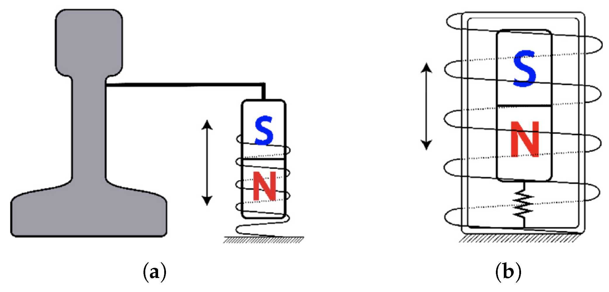
Figure 1. Linear electromagnetic generator [12]: (a) magnet attached to a vibrating element; (b) magnet suspended.
Energies 18 01588 g001
Figure 2. Summary diagram.
Energies 18 01588 g002
Figure 3. Schematic representation of a 1DOF TEMEH.
Energies 18 01588 g003
Figure 4. Equivalent circuit of the TEMEH.
Energies 18 01588 g004
Figure 5. Examples of frequency-up conversion harvesters: (a) Xu et al. [27]; (b) Halim et al. [28]; (c) Li et al. [31] Key components are numbered and labeled as: 1. Piezoelectric stack 2. Housing 3. Magnet array 4. Sliding bearings 5. Coil array 6. Primary spring.
Energies 18 01588 g005
Figure 6. Examples of NES: (a) Kremer et al. [37] The components labeled in the image are: (1) base (2) primary system (3) NES; (b) Pennisi et al. [39].
Energies 18 01588 g006
Figure 7. Force-displacement curves for “hardening” and “softening” springs.
Energies 18 01588 g007
Figure 8. Magnetic suspensions [44]: (a) double-sided; (b) asymmetric.
Energies 18 01588 g008
Figure 9. Non-linear stiffness FRFs [45]: (a) “hardening”; (b) “softening”.
Energies 18 01588 g009
Figure 11. TEMEHs with MEMS springs: (a) Lei et al. [54]; (b) Nicolini et al. [57].
Energies 18 01588 g011
Figure 12. TEMEHs with magnetic springs: (a) Lo Monaco et al. [59]; (b) Nico et al. [63]; (c) Salauddin et al. [65]; (d) Su et al. [66].
Energies 18 01588 g012
Figure 13. TEMEHs with hybrid configurations: (a) Costantinou et al. [67]; (b) Aldawood et al. [68] On the left is the traditional design, while on the right is the enhanced one; (c) Fan et al. [69].
Energies 18 01588 g013
Figure 14. 2DOF TEMEHs: (a) Ung et al. [70]; (b) Feng et al. [34]; (c) Masood Ahmad et al. [71]; (d) Tao et al. [72]; (e) Lo Monaco et al. [46]; (f) Fan et al. [74].
Energies 18 01588 g014
Table 1. Vibrational energy harvesting methodologies and power densities [9,10].
MethodologyPower DensityAdvantagesDisadvantages
Electromagnetic200–800 μ Wcm−3Wide bandwidthMagnetic leakage
High currentLow voltage
High powerLarge size
Piezoelectric20–330 μ Wcm−3High voltageLow current
Simple structureEasy aging
Small sizeLow power
Electrostatic180 μ Wcm−3Low frequenciesStart-up power
High integrabilityLow currents
Table 2. Comparison between 1DOF TEMEHs.
ReferenceSpringVolume (cm3)Frequency (Hz)Acceleration (g)Power (mW)NPD (mWcm−3g−2)FoMv (%)
[28]Mechanical6.475.172.062.150.0782.25
[47]Mechanical-78.82.007.22--
[48]Mechanical137.961.70.033.6129.10.37
[51]Mechanical30550.228.323.63.71
[52]Mechanical34.841.213.710.1070.11
[53]Mechanical1.610.10.520.721.669.84
[54]MEMS1.81240.50.210.470.21
[55]MEMS5.9 163.711.180.200.23
[56]MEMS0.04513810.2655.8916.12
[57]MEMS17315.10.375.00.210.12
[59]Magnetic61.540.539.02.5410.8
[63]Magnetic8.1211.50.42.061.593.70
[64]Magnetic938 11.70.54.380.0190.075
[65]Magnetic32.76110.51.10.130.26
[66]Magnetic-50.087.6 × 10 −5--
[67]Hybrid 2614712.90.480.24
[68]Hybrid 3222110.470.01.971.59
[69]Hybrid 31290.81.150.150.78
1 Volume is not explicitly stated but is computed from power density values or estimated through known dimensions. 2 MEMS-Magnetic. 3 Mechanical-Magnetic.
Table 3. Comparison between 2DOF TEMEHs.
ReferenceSpringVolume (cm3)Frequency (Hz)Acceleration (g)Power (mW)NPD (mWcm−3g−2)FoMv (%)
[70]Mechanical600 36.0, 14.60.5350 12.333.10
[34]Mechanical53.958, 74.50.2710.9 12.770.46
[71]Mechanical3334.4, 5.50.0910.7 23.971.26
[72]MEMS0.29326, 3910.120.96 × 10−6 22.2 × 10−41.4 × 10−5
[46]Magnetic2263.4, 6.70.48.25 10.230.59
[74]Magnetic26.37.5, 18.50.52.58 10.391.18
1 At the first resonance frequency. 2 At the second resonance frequency. 3 Volume is not explicitly stated but is estimated based on magnet data.
Disclaimer/Publisher’s Note: The statements, opinions and data contained in all publications are solely those of the individual author(s) and contributor(s) and not of MDPI and/or the editor(s). MDPI and/or the editor(s) disclaim responsibility for any injury to people or property resulting from any ideas, methods, instructions or products referred to in the content.