Article

Investigation on Graphitization, Surface Functional Groups, and Oxidation Behavior of Soot Particulate Along Exhaust Pipe of Gasoline Direct Injection Engine

by
Zhiyuan Hu
*,
Li Yin
,
Jiayi Shen
,
Zhangying Lu
,
Piqiang Tan
and
Diming Lou
School of Automotive Studies, Tongji University, Shanghai 201804, China
*
Author to whom correspondence should be addressed.
Energies 2025, 18(7), 1684; https://doi.org/10.3390/en18071684
Submission received: 4 February 2025 / Revised: 23 February 2025 / Accepted: 4 March 2025 / Published: 27 March 2025
(This article belongs to the Section B: Energy and Environment)

Abstract

:
This study investigated the changes in graphitization, surface functional groups, and oxidation behavior of soot particulates along an exhaust pipe of a gasoline direct injection (GDI) engine using Raman spectroscopy, X-ray photoelectron spectroscopy (XPS), and thermogravimetric analysis (TGA). The main findings were as follows: The oxidation temperature of soot particulates was between 300 °C and 650 °C. The soot particulates generated for a higher engine load or near the exhaust valve tended to exhibit a lower ratio of a disordered graphite lattice and amorphous carbon. As the engine load increased, the graphitization degree of soot particulates became higher and the content of oxygen-containing functional groups and oxidation activity of soot particulates became lower, meaning that it became more difficult for the soot particulate to be oxidized. Under a light load, as the engine speed increased, the disorder of the edge array of soot particles became higher, the content of oxygen-containing functional groups and oxidation activity became higher, and the soot particles were more easily oxidized. On the other hand, with an increase in engine speed under a heavy load, the microscopic disorder of soot particulates decreased; lower contents of oxygen-containing functional groups and oxidation activity were observed and oxidation became more difficult. Moreover, with increasing transportation distance along the exhaust pipe of the GDI engine, the graphitization degree, content of surface functional groups, and oxidation behavior of soot particulate presented changes similar to the increasing engine speed under a light load, and oxidation became easier.

1. Introduction

Gasoline direct injection (GDI) engines, which have the advantages of a large compression ratio, high thermal efficiency, and good fuel economy, have become the mainstream power source for light-duty vehicles. In addition, for GDI engines, we report greater particulate mass (PM) and a significantly higher particle number (PN) than that of port fuel injection (PFI) gasoline engines because of wall-film pool combustion and local concentration area combustion of gasoline in cylinders [1,2]. It is worth noting that PN emissions from GDI engines are one order of magnitude higher than that of PFI gasoline engines [3], which is even higher than that of diesel engines equipped with a diesel particulate filter (DPF) [4]. Moreover, PN emissions from a GDI engine are mainly ultrafine particles with a diameter less than 100 nm [5], which shows a bimodal logarithmic distribution with the particles’ diameter, with two peak values of PN near 10 nm and 60 nm, respectively [6], and contain a certain proportion of particles with a diameter below 23 nm [7]. Therefore, controlling the PN emission of GDI engines has become a key issue during their development process. Countries around the world are implementing increasingly stringent emission regulations to control pollutant emissions from vehicles. A PN including particles with a diameter less than 23 nm from a GDI engine has been limited by regulations [8]. For example, the PN limit of Euro 7 issued on 12 April 2024 expanded the controlled diameter of particles from 23 nm to 10 nm [9]. It is, therefore, highly necessary to develop more efficient PN control devices for GDI engines, especially for particles less than 23 nm in diameter.
Nowadays, wall-flow gasoline particulate filters (GPFs) have become the standard after-treatment configuration to reduce both PM and PN emissions from GDI engines [10]. The filtration efficiency of GPFs for PN emissions with a diameter less than 23 nm has become the key issue in determining whether GDI engines can meet the Euro 7 regulation. The PN filtration efficiency, which is related to carbon load, exhaust flow rate and particles’ diameter, is the key factor that indicates its purification effect of particulate filters [11,12]. But the carbon load estimation of GPFs often uses the pressure difference method or the open-loop carbon accumulation estimation method that is similar to a DPF and has significant uncertainty [13]. The accuracy of carbon load estimation can be significantly improved by incorporating physical characteristics such as particle diameter into the estimation model [14]. On the other hand, the physical and chemical characteristics, such as amount, diameter, oxidation activity, etc., of soot particulates at the inlet of a GPF significantly affect its performance [15]. For example, the diameter of particles affects the filtration efficiency of the PN and its deposition distribution within the GPF [16]. The filtration efficiency of a wall-flow particulate trap unit for medium particles with a diameter of 30–230 nm is relatively low [17]. The filtration efficiency of GPFs would be significantly improved if the inlet PN was increased by one order of magnitude [18]. Furthermore, the activation energy of soot particulates is another significant factor that affects the oxidation process within a particulate filter [19], as well as the regeneration control of GPFs [20]. Therefore, the physicochemical characteristics, such as the PN, graphitization, surface functional groups, oxidation behavior, etc., of soot particulates at the inlet of a GPF should be studied carefully.
The physicochemical characteristics of soot particulates at the inlet of a GPF are affected by many factors, such as fuel [21], its injection timing [22], ignition timing [23], operating condition, [24] lubricating oil [25], three-way catalyst converter (TWC) [17] and exhaust gas recirculation (EGR) [26], as well as the transportation distance along the exhaust pipe [27]. Relatively few studies have been conducted on the effect of transport distance on soot particles in GDI engines compared to factors, such as fuel, ignition, EGR, and TWC. Only a few scholars have conducted relevant studies. For example, a series of changes occur during the transportation process of soot particulates along an exhaust pipe of a GDI engine, such as oxidation, agglomeration, thermophoresis, etc. [28]. As a result, the number, diameter and oxidation behavior of soot particulates would clearly change along the exhaust pipe of a GDI engine. Liu et al. [29] examined the evolution of particles in the exhaust gas of a single-cylinder SI engine equipped with an exhaust plenum chamber, and their findings revealed a decrease in the PN with a shift in the sampling point from 5 cm upstream to 115 cm downstream of the exhaust plenum chamber. Spiess et al. [30] found that the exhaust flow becomes more laminar, which slows down the flow rate and consequently improves the filtration efficiency of the GPF by increasing the distance between the TWC and GPF. Fu et al. [27] found that the proportion of nucleation mode particles and fringe length of soot particulate decreased, but the separation distance, tortuosity, and disorder degree of fringes increased as the soot particulate was transported along exhaust pipe of GDI engine. However, the changing patterns of graphitization, surface functional groups, and oxidation behavior of soot particulate of GDI engine along the exhaust pipe are still unclear.
To sum up, improving the filtration efficiency of GPF for particles below 23 nm is a key issue in determining the ability of GDI engines to meet the Euro 7 PN limit. And the physical and chemical characteristics such as diameter and oxidation activity of soot particulate at the inlet of GPF significantly affect the filtration efficiency. Moreover, the transportation process of soot particulate along the exhaust pipe engine is one of the key factors that affect its physical and chemical characteristics and further impact the filtration efficiency of GPF. However, research about the influence of transporting on soot particulate is not conducted enough for GDI engines. And the changing patterns of graphitization, surface functional groups, and oxidation behavior of soot particulate along the exhaust pipe of GDI engine are still unclear. Therefore, the impact of transporting on graphitization, surface functional groups, and oxidation behavior of soot particulate should be one of the most important scientific and technical issues for GPFs and is very much in need of further investigation.
This study consists of an introduction, experimental setup, results, discussion, and conclusion. It investigates the graphitization, surface functional groups, and oxidation behavior of soot particulates collected at different positions along the exhaust pipe of a GDI engine using Raman, XPS, and TGA. The purposes of this study were to clarify the impacts of engine load, speed, and transport distance on the graphitized structure, surface functional groups, and oxidation behavior of soot particulate, to clarify the variation rules of soot particulate along the exhaust pipe of the GDI engine, and to help analyze the characteristics of soot particulate at the inlet of GPF, especially the graphitization and surface functional groups. The results of this study can provide theoretical references and insights for the design and layout of GPFs to purify PN emissions from GDI engines with diameters below 23 nm.

2. Experimental Setup

2.1. Experimental Engine and Fuel

The test engine is a turbocharged inline 4-cylinder EA211 GDI engine manufactured in Shanghai, China. Table 1 lists the main technical parameters of the GDI engine. Table 2 lists the main physicochemical parameters of the tested fuel.

2.2. Sample Points and Operating Conditions

Three sampling points were picked to investigate the changes, including graphitization, surface functional groups, and oxidation behavior of soot particulate, along the exhaust pipe of the GDI engine. Specifically, the first sampling point was positioned at 0.3 m after the turbocharger outlet (i.e., before TWC inlet). Subsequently, the other sampling points were established every 0.5 m behind the previous sample points. That is, the second sampling point was positioned at 0.5 m behind the first sampling point (i.e., between TWC outlet and GPF inlet), and the third sampling point was positioned at 1.0 m (i.e., behind GPF outlet). The sampling time was set to 1 h, aiming to ensure that enough soot particulate was collected for subsequent offline analysis. For each engine operating condition, each sampling point was subjected to three repeated experiments to ensure accuracy. Error analysis was conducted based on these repeated measurements’ data.
The oxidation, agglomeration and thermophoresis of soot particulate in exhaust pipes are deeply affected by the engine operating condition, resulting in changes to the physicochemical characteristics of soot particulate [31]. Temperature is one important effect factor, which influences the oxidation of soot particulate [32], and the exhaust temperature should be higher than the light-off temperature of an after-treatment system. Therefore, two engine loads (i.e., BMEP 0.2 MPa and BMEP 0.8 MPa) were selected to reflect the influence of temperature on changes in soot particulate. One the other hand, the flow rate of exhaust gas would affect the flow field in the exhaust pipe and, thus, might influence the generation of particles. Two different engine speeds (i.e., 2000 rpm and 4500 rpm) were selected to reflect the influence of the gas flow rate on particle generation. Table 3 lists the selected operating conditions.

2.3. Experimental Equipment and Procedure

The test equipment consists of an engine test bench, PM sampling system, and offline PM analysis system, which includes a laser Raman spectrometer, XPS, and TGA for soot particulate characterization analyses. Figure 1 shows a schematic view of the experimental equipment and procedure.
After 5 min of stable engine operation under specified operating conditions, the sampling is taken directly from raw exhaust gas through a single-channel sampling device with a 90 mm quartz filter produced by Whatman, Maidstone, UK as the carrier, where the simple flow is 50 L/min. The sampling tube was surrounded by thermal insulation material and heated to ensure the temperature of sampled exhaust gas remains constant, preventing the collected soot particles from being affected by moisture. When sampling was completed, the sampled membrane was divided into several small portions for the following graphitized structure, surface functional groups, and oxidation behavior analyses.
The graphitization of soot particulate was analyzed using a LabRAM Raman spectrometer produced by HORIBA, Paris, France. The key parameters of the Raman spectrometer include spectral resolution (≤0.35 cm−1), spectral range (50~9000 cm−1), and spectral repeatability (≤±0.03 cm−1). The first-order Raman spectra of the selected samples were obtained by scanning in a frequency range of 1100~1800 cm−1, from where the high-frequency characteristic peaks near the Raman shift of 1590 cm−1 (graphite peak) and 1360 cm−1 (Defacts peak) were obtained. The ratio of peak intensity values of the graphite peak and Defacts peak can be used to characterize the ordering degree of the microcrystalline structure and the graphitization degree of carbon materials.
The surface functional groups of soot particulate were analyzed utilizing a PHI 5300 (XPS) produced by PE, Philadelphia, PA, USA, with an analysis area of 0.7 × 0.3 mm2, a scanning half peak width of 0.65 eV, a comprehensive scanning energy range of 0~1100 eV, and an energy resolution of 0.80 eV. The peaks of the carbon spectrum are resolved through the utilization of XPSPEAK software 4.1, and the curve was fitted using the Gauss/Lorentz (G/L = 0.5) method.
The analysis of the oxidation behavior of soot particulate was conducted utilizing a Q600 SDT TGA produced by TA instruments, New Castle, DE, USA, with a weighing sensitivity of 0.1 μg, a weighing accuracy of ±0.02%, a maximum heating temperature of 1000 °C, a maximum heating rate of 500 °C/min, and a mass flow from 0.1 to 200 mL/min. The sample mass was 5 mg and the ventilation flow rate was 100 mL/min. The PM sample was heated in air from 100 °C to 800 °C with a heating rate of 10 °C/min. A blank quartz filter membrane was set up as a control group in the experiment.

3. Results and Discussion

3.1. Graphitization of Soot Particulate

3.1.1. Raman Spectrum Analysis

Raman spectroscopy is widely utilized in evaluating the level of graphitization of soot particulate derived from diesel and gasoline engines due to its ability to provide essential information on lattice dimensions and defects within graphite layers [33]. The 4L1G fitting method proposed by Sadezky et al. [34] was employed for analysis, involving fitting procedures at five specific Raman shifts: 1200 cm−1 (D4, Lorentzian), 1350 cm−1 (D1, Lorentzian), 1500 cm−1 (D3, Gaussian), 1590 cm−1 (G, Lorentzian), and 1620 cm−1 (D2, Lorentzian). The D4 peak corresponds to an asymmetric graphite layer [35].
Figure 2 shows a comprehensive five-band curve fitting of the initial Raman spectrum, where D1 peaks represent the presence of amorphous carbon. The D3 peak indicates vibrations originating from amorphous carbon, with its magnitude and intensity intricately linked to functional groups, organic components, and debris within the particulate matter. The G peak reflects the telescopic vibration symbolizing the C-C bond within the graphite lattice, exemplifying the characteristic spectrum of an ideal graphite structure, whereas the D2 peak arises from asymmetry among the graphite layers [36]. In this study, the Raman spectrum region from 1000 to 2000 cm−1 was specifically examined. The analysis primarily focuses on the D1, D3, and G peaks to evaluate the graphitization degree of soot particulate samples. Notably, the intensity peak of G at 1590 cm−1 was used as a reference for normalizing the Raman spectra of all samples to ensure consistent analysis results.

3.1.2. Graphitized Structure of Soot Particulate

Figure 3 presents the Raman parameters deduced from the fitting and computation of Raman spectra of soot particulate from the GDI engine at three sampling points, where ID1 represents the integrated intensity of the D1 amorphous carbon content peak, and IG represents the integrated intensity of the G peak caused by the stretching vibration of the C-C bond in the graphite lattice. ID1/IG serves to characterize the structural flaws within the base plane of the graphene layer and can be effectively employed to approximate the graphitization degree of soot particulate [37]. AD1 is closely linked to carbon atoms located at the edge of the graphene layer [38], AD3 is related to amorphous carbon, and AG is correlated with graphite carbon. The order degree of graphite lattice and proportions of amorphous carbon to graphite carbon can be analyzed by AD1/AG and AD3/AG, respectively [39]. D1-FWHM signifies the full width at half maximum of the D1 peak, effectively reflecting the distribution of crystallite sizes [40]. A smaller D1-FWHM implies a higher degree of order within the soot nanostructure.
As shown in Figure 3, it is evident that as the engine load increases, the in-cylinder mixture density increases, leading to a rise in the internal cylinder temperature [41]. And the oxidative impact on soot particulate is also intensified. So, there is a decrease in ID1/IG, AD1/AG, AD3/AG, and D1-FWHM, which signifies a reduction in structural defects within the base plane of the graphene layer, a lower proportion of disordered graphite lattice and amorphous carbon, a higher order of nanostructure array, and an elevated degree of graphitization. Furthermore, with an increase in the transport distance along the exhaust pipe, the ID1/IA, AD1/AG, and AD3/AG of soot particulate increase, which indicates more structural defects in the base plane of the graphene layer, greater ratio of disordered graphite lattice and amorphous carbon, larger disorder of the nanostructure array, and lower degree of graphitization. Firstly, there is collision and oxidization when soot particles pass through the exhaust pipe, which is one of the factors that affect the crystalline structure of soot particles. Secondly, the temperature of exhaust gas decreases when the transportation distance increases. Then, the C=O% content functional groups adsorbed on the surface of particles increase, making them more susceptible to oxidation. This leads to a reduction in the degree of graphitization.

3.2. Surface Functional Groups of Soot Particulate

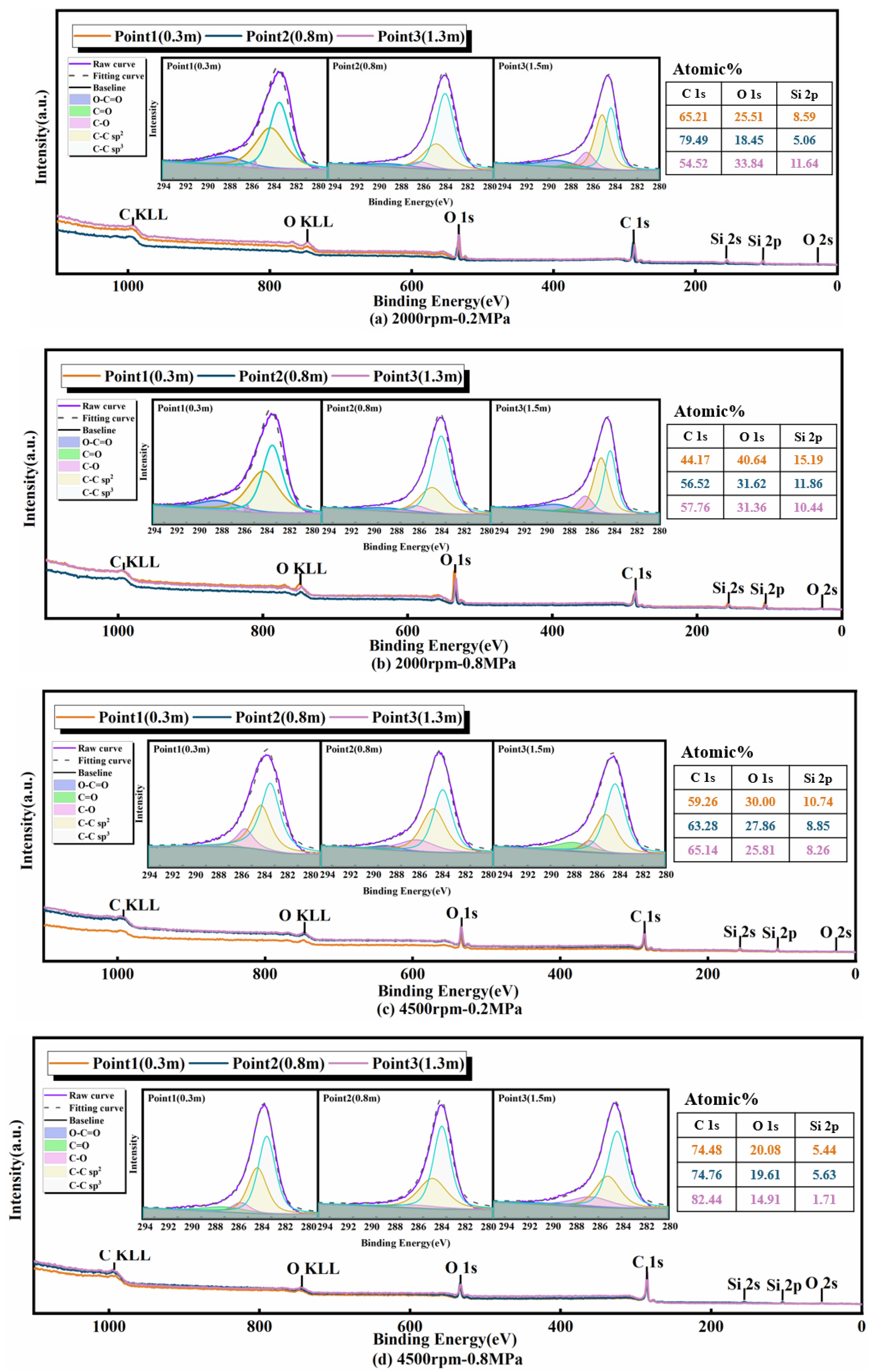
3.2.1. XPS Full-Spectrum Analysis

Figure 4 illustrates the XPS full spectrum of soot particulate from the tested GDI engine along the exhaust pipe. Notably, the XPS full spectrum scanning patterns of the soot particulate samples gathered under various operating conditions exhibit a fundamental similarity, albeit with distinct peak values. Two main characteristic peaks are observed across all soot particulate samples, located near 285 eV and 536 eV, representing the C 1s peak and O 1s, and the C 1s peak can be deconvoluted into four distinct peaks: sp2 (284.4 eV), sp3 (285.2 eV), C-OH (286.6 eV), C=O (288 eV) [42]. There is some Si, which comes from the quartz filter membrane in the XPS full spectrum.

3.2.2. O/C Ratio

Oxygen and carbon are the main components of soot particulate. The molar mass ratio of O/C is determined by analyzing the characteristic areas of C 1s and O 1s peaks in the XPS full spectrum. A higher O/C ratio suggests a higher proportion of oxidized carbon within the soot particulate, indicating lower thermal stability and increased susceptibility to be oxidated [43]. Figure 5 shows the O/C ratio of soot particulate along the exhaust pipe of the GDI engine.
It can be seen from Figure 5 that the O/C ratio of soot particulate along the exhaust pipe of the tested GDI engine lies within a range of 0.2 to 1. In particular, the O/C ratio of soot particulate declines as the engine load increases at high speed (i.e., 4500 rpm), owing to the escalation of the in-cylinder temperature and the heightened oxidative impact on soot particulate. Meanwhile, the O/C ratio of soot particulate diminishes with an increase in engine speed at high load (i.e., BMEP 0.8 MPa) due to the heightened gas flow motion, the more uniform mixture gas, and, consequently, the more thorough the combustion within the cylinder [44]. Moreover, with increasing transport distance along the exhaust pipe of the GDI engine, the O/C ratio of soot particulate increases, except under low-speed and low-load operating conditions (i.e., 2000 rpm, BMEP 0.2 MPa). This is because of some semi-liquid HCs beginning to liquefy to form oxygen-containing SOF and adsorbed by soot particles as the exhaust gas temperature drops with increasing transport distance. Meanwhile, the collision of particles during the exhaust transportation process is to produce large-diameter particles, which increase the surface area and can adsorb more SOF.
Particularly, during operation under low-speed and low-load conditions, the engine tends to emit a considerable quantity of semi-volatile particles [45]. Consequently, under these specific operating conditions, the initial decrease in the O/C ratio of soot particulate is due to the adsorption and condensation of semi-volatile particles that adhere to the soot as exhaust gas begins its journey through the exhaust pipe. Subsequently, the soot particulate absorbs certain soluble organic compounds with the decrease in exhaust temperature, leading to an apparent rise in O/C ratio. Regarding Point 1 (i.e., 0.3 m after the turbocharger outlet) under operating conditions of 2000 rpm-0.2 MPa, the O/C ratio of soot particulate experiences a decline with the increase in either engine speed or load. However, the O/C ratio of soot particulate for Point 2 (i.e., 0.8 m after the turbocharger outlet) and Point 3 (i.e., 1.3 m after the turbocharger outlet) exhibits distinct changing trends with the increase in engine speed or load, primarily due to the aforementioned reasons.

3.2.3. sp3/sp2 Ratio

The main chemical configurations of carbon atoms are sp2 and sp3 hybridized forms, where sp2 hybridized carbon atoms are predominantly located at the core of the particles, exhibiting lower oxidation activity. On the other hand, the sp3 hybridized carbon atoms are primarily localized at the particle edges, indicating a lower degree of graphitization and higher oxidation activity [46]. The ratio of sp3/sp2 hybridization serves as a valuable metric for characterizing the level of microcrystalline structure ordering. An increase in the sp3/sp2 ratio suggests a higher amorphous content within the structure of the soot particles [47], making them more susceptible to oxidation. Figure 6 illustrates the sp3/sp2 ratio of soot particulate along the exhaust pipe of the GDI engine.
It can be seen from Figure 6 that sp3/sp2 falls within a range of 0.5–0.8. Corresponding to the results and reasons from Raman analysis, as the engine load increases from 0.2 MPa to 0.8 MPa, the sp3/sp2 ratio tends to increase across all sampling points (i.e., 0.3 m, 0.8 m, and 1.3 m). This trend is more pronounced at lower engine speeds (i.e., 2000 rpm), where soot particulates exhibit a noticeable increase in the sp3/sp2 ratio, indicating a rise in amorphous carbon content. At higher engine speeds (i.e., 4500 rpm), the sp3/sp2 ratio also increases with engine load, though the change is less significant compared to that of 2000 rpm. And the increasing sp3/sp2 ratio under higher loads suggests that higher engine loads favor the formation of more disordered carbon structures, which are less stable and more prone to oxidation. The sp3/sp2 ratio increases with the exhaust transportation process. This trend signifies that the sampling position farther away from the exhaust port correlates with a higher amorphous content in soot particulate, rendering it more prone to oxidation.

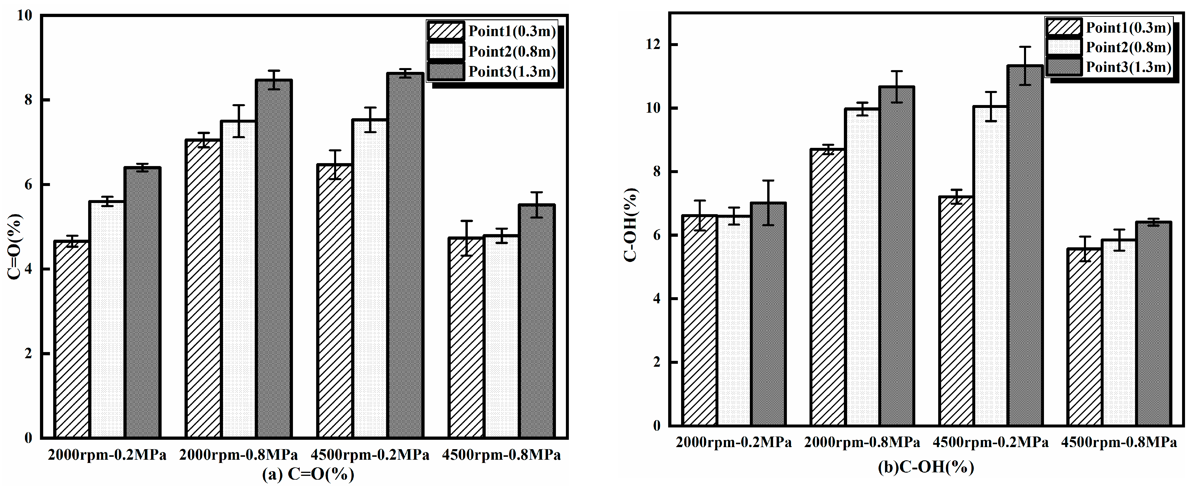
3.2.4. Surface Functional Groups

The proportion of oxygen-containing functional groups serves as an indicator of the thermal stability of the carbon layer. A higher proportion of oxygen-containing functional groups means that the carbon layer is less thermally stable and increases its susceptibility to oxidation [48]. In this study, the analysis primarily focuses on C-OH and C=O carbon–oxygen functional groups. Figure 7 provides an overview of the C=O and C-OH content of soot particulate along the exhaust pipe of the GDI engine.
As shown in Figure 7, the changes in and reasons for the C=O% and C-OH% of soot particulate at different engine speeds, loads, as well as the distance away from the exhaust valve are basically similar to the O/C ratio. That is, both the C=O% and C-OH% functional groups of soot particulate from the tested GDI engine increase with increasing transport distance, also indicating that it can more easily oxidate the soot particulate in the exhaust process of a GDI engine.

3.3. Oxidative Behavior of Soot Particulate

3.3.1. TG&DTG Analysis

The thermogravimetric (TG) curve derived from the thermogravimetric test (conducted in an air atmosphere, with a heating rate of 10 °C/min, starting from 100 °C and heating up to 800 °C) serves as an effective means to depict the oxidation process of soot particulate. And the derivative thermogravimetry (DTG) curve portrays the alteration in the weight change rate concerning temperature, and it entails the computation of the derivative of the TG curve, representing the curve’s slope at each temperature. Figure 8 depicts the TG&DTG results of soot particulate along the exhaust pipe of the GDI engine.
As seen from Figure 8, the main oxidation temperature of soot particulate from the tested GDI engine is from 300 °C to 650 °C. There is no obvious difference in the distribution patterns of TG&DTG curves under different engine speeds, loads, and exhaust transport distances, except the peak temperature of DTG curves. Specifically, the oxidation process of soot particulate from the tested GDI engines can be classified into three phases: 100~300 °C, 300~650 °C, and above 650 °C, respectively. Phase I, occurring between 100 and 300 °C, involves the removal of a low-temperature soluble organic fraction (SOF) and water absorbed on the surface of soot particulate through vaporization and oxidation. Phase II, occurring between 300 and 650 °C, primarily accounts for mass loss attributed to the oxidation of soot particulate. Phase III, occurring above 650 °C, witnesses only a small quantity of residual oxidizable substances, such as low activation soot, metals, and minerals continuing to undergo oxidation, with the mass loss rate nearly approaching zero.
By comparing the TG&DTG results under different engine speeds, it can be observed that in Phase II, the mass loss rate at 4500 rpm is significantly higher. When the temperature is above 650 °C, the mass loss rate becomes more gradual and approaches zero more quickly. At the same engine speed, as the load increases, the peak mass loss rate shifts to a higher temperature. For instance, at 0.2 MPa, the maximum mass loss rate occurs at around 500 °C, whereas at 0.8 MPa, the peak mass loss rate is observed at around 550 °C.

3.3.2. Activation Energy of Soot Particulate

The activation energy (Ea) refers to the minimum energy required for molecules involved in a reaction to transition from a stable state to an active state [49], which reflects the rate of chemical reactions in oxidation processes [50] as well. The soot particulate is more easily oxidized if the Ea is smaller.
Ea is calculated based on TG&DTG according to the Arrhenius theorem and Coats–Redfern equation in this study.
d α d t = k f ( α ) = A exp ( E a R T ) ( 1 α ) n
where α is the conversion rate of soot particulate mass; t is the time; k is the constant of Arrhenius; A is the frequency factor; T is thermodynamic temperature; R is the constant of gas; n is the reaction order (n = 1 for the soot particulate from GDI engines). Table 4 lists the activation energy of soot particulate along the exhaust pipe of the GDI engine.
As listed in Table 4, the activation energy of soot particulate along the exhaust pipe of the tested GDI engine ranges from 100 kJ/mol to 165 kJ/mol. Bogarra et al. [51], Piqueras et al. [52] and Easter et al. [53] obtained similar results. An increase in engine load results in a rise in the activation energy of soot particulate, primarily due to a higher degree of graphitization, lower sp3/sp2 ratio, lower O/C ratio, and reduced C=O% and C-OH% content of oxygen-containing functional groups. An increase in engine speed or transportation distance along the exhaust pipe leads to a decrease in the activation energy of soot particulate. This trend is attributed to a lower degree of graphitization, a higher sp3/sp2 ratio, O/C ratio, and higher C=O% and C-OH% content functional groups within the soot. That is, the soot particulate becomes more difficult to oxidate with an increase in the engine load but becomes easier to oxidate with an increase in engine speed and/or transportation distance along the exhaust pipe of the GDI engine.

4. Conclusions

This study investigated the graphitization, surface functional groups, and oxidation behavior of soot particulate along the exhaust pipe of a GDI engine. The impact of engine load, speed, as well as transportation distance along the exhaust pipe on the graphitized structure, oxygen-containing functional groups, and oxidation behavior of soot particulate was analyzed. The results of this study could be helpful for engineers to understand the impact of engine load, speed, and transportation distance along the exhaust pipe on particulate from the GDI engine. It can also provide some references and insights for engineers for the design and layout of GPFs to purify PN emissions from GDI engines. The main findings are shown below:
  • The main oxidation temperature range of soot particulate from GDI engines ranges from 300 °C to 650 °C. The soot particulate generated at higher engine loads, or near the exhaust valve, has fewer structural defects in the base plane of the graphene layer, lower ratio of disordered graphite lattice, and higher degree of graphitization, exhibiting lower oxidation activity.
  • The transportation distance along the exhaust pipe has a significant impact on the graphitization degree, oxygen-containing functional groups, and oxidation activity of soot particlute from a GDI engine. With an increase in the transportation distance, the degree of graphitization and activation energy of soot particulate decrease, and the sp3/sp2 ratio, O/C ratio, C=O% content, and C-OH% content increase, rendering the soot particulate easier to oxidize. At 2000 rpm-0.8 MPa, the sp3/sp2 ratio increased by 60.3% and the C=O% content increased from 8.70% to 10.67% after a 1 m increase in the exhaust transport distance. The activation energy decreased by 28.62 kJ/mol with increasing transport distance.
  • The engine load has a significant impact on the graphitization, oxygen-containing functional groups, and oxidation behavior of soot particulate of a GDI engine. With an increase in the engine load, the graphitization degree and activation energy of soot particulate rise; the sp3/sp2 ratio, O/C ratio, C=O% content, and C-OH% content decrease, making the soot particulate more resistant to oxidation. Under a high engine load (4500 rpm-0.8 MPa), the activation energy increased by 22.37 kJ/mol, while the C=O% content decreased from 8.63% to 5.52% compared to the low engine load (4500 rpm-0.2 MPa).
  • Engine speed has a certain impact on the graphitization, oxygen-containing functional groups, and oxidation behavior of soot particulate. With an increase in engine speed, there are no apparent changes in graphitization but a certain degree of reduction in the oxidation activity. In particular, the O/C ratio, sp3/sp2 ratio, C=O% content, and C-OH% content of soot particulate decrease with increasing engine speeds under high load but increase with an increase in engine speed under a light load. With the engine speed increase, the sp3/sp2 ratio decreased by 40.32%, and the C-OH% content decreased by 17.12%.

Author Contributions

Methodology, D.L.; Formal analysis, P.T.; Investigation, Z.H.; Data curation, J.S. and Z.L.; Writing—original draft, L.Y.; Writing—review & editing, J.S. and Z.H. All authors have read and agreed to the published version of the manuscript.

Funding

This research was funded by the Municipal Natural Science of Shanghai (22ZR1463500).

Data Availability Statement

The original contributions presented in the study are included in the article, further inquiries can be directed to the corresponding author.

Conflicts of Interest

The authors declare no conflict of interest.

List of Abbreviations

AbbreviationDescription
GDIGasoline direct injection
XPSX-ray photoelectron spectroscopy
TGAThermogravimetric analysis
PMparticulate mass
PNparticles number
PFIport fuel injection
GPFgasoline particulate filter
DPFdiesel particulate filter
TWCthree-way catalyst converter
EGRexhaust gas recirculation
BMEPbrake mean effective pressure
4L1G Four-Layer One-Gaussian method
C=O%the quality score of C=O
C-OH%the quality score of C-OH
HChydrocarbons
SOFsoluble organic fraction
TG&DTGThermogravimetry & Derivative Thermogravimetry
EaThe activation energy

References

  1. Lu, L.; Pei, Y.; Qin, J. Experimental study on spatial distribution characteristics of cylinder-wall oil films under fuel spray impinging condition of GDI engine. Energy 2022, 254, 124381. [Google Scholar] [CrossRef]
  2. Gordon, T.D.; Presto, A.A.; May, A.A. Secondary organic aerosol formation exceeds primary particulate matter emissions for light-duty gasoline vehicles. Atmos. Chem. Phys. 2014, 14, 4661–4678. [Google Scholar]
  3. Gertler, A.W. Diesel vs. gasoline emissions: Does PM from diesel or gasoline vehicles dominate in the US. Atmos. Environ. 2005, 39, 2349–2355. [Google Scholar] [CrossRef]
  4. Jasiński, R.; Strzemiecka, B.; Koltsov, I. Physicochemical Analysis of the Particulate Matter Emitted from Road Vehicle Engines. Energies 2021, 14, 8556. [Google Scholar] [CrossRef]
  5. Joshi, A. Review of vehicle engine efficiency and emissions. SAE Int. J. Adv. Curr. Pract. Mobil. 2019, 1, 734–761. [Google Scholar] [CrossRef]
  6. Hu, Z.; Lu, Z.; Song, B.; Quan, Y. Impact of test cycle on mass, number and particle size distribution of particulates emitted form gasoline direct injection vehicles. Sci. Total Environ. 2021, 262, 143128. [Google Scholar] [CrossRef]
  7. Kontses, A.; Triantafyllopoulos, G.; Ntziachristos, L. Particle number (PN) emissions from gasoline, diesel, LPG, CNG and hybrid-electric light-duty vehicles under real-world driving conditions. Atmos. Environ. 2020, 222, 117–126. [Google Scholar] [CrossRef]
  8. Samaras, Z.C.; Andersson, J.; Bergmann, A. Measuring automotive exhaust particles down to 10 nm. SAE Int. J. Adv. Curr. Pract. Mobil. 2020, 3, 539–550. [Google Scholar] [CrossRef]
  9. Xin, Y.; Zhang, H.; Li, P. Low-content and highly effective zoned Rh and Pd three-way catalysts for gasoline particulate filter potentially meeting Euro 7. J. Rare Earths 2023, 41, 905–916. [Google Scholar] [CrossRef]
  10. Joshi, A.; Johnson, T.V. Gasoline Particulate Filters-a Review. Emiss. Control Sci. Technol. 2018, 4, 219–239. [Google Scholar] [CrossRef]
  11. McCaffery, C.; Zhu, H.; Li, C. On-road gaseous and particulate emissions from GDI vehicles with and without gasoline particulate filters (GPFs) using portable emissions measurement systems (PEMS). Sci. Total Environ. 2020, 710, 136366. [Google Scholar] [CrossRef] [PubMed]
  12. Chen, W.; Ou, Q.; Chang, C. Using aerosols to create Nano-scaled membranes that improve gasoline particulate filter performance and the development of Wafer-based membrane coated filter analysis (WMCFA) method. Sep. Purif. Technol. 2022, 284, 120310. [Google Scholar] [CrossRef]
  13. Nicolin, P.; Boger, T.; Dietrich, M.; Haft, G.; Bachurina, A. Soot Load Monitoring in Gasoline Particulate Filter Applications with RF-Sensors. SAE Tech. Pap. 2020. [Google Scholar] [CrossRef]
  14. Orihuela, M.P.; Gómez-Martín, A.; Miceli, P. Experimental measurement of the filtration efficiency and pressure drop of wall-flow diesel particulate filters (DPF) made of biomorphic Silicon Carbide using laboratory generated particles. Appl. Therm. Eng. 2018, 131, 41–53. [Google Scholar] [CrossRef]
  15. Adam, F.; Olfert, J.; Wong, K.; Kunert, S.; Richter, M.J. Effect of Engine-Out Soot Emissions and the Frequency of Regeneration on Gasoline Particulate Filter Efficiency. SAE Tech. Pap. 2020. [Google Scholar] [CrossRef]
  16. Li, Z.; Shen, B.; Zhang, Y. Simulation of deep-bed filtration of a gasoline particulate filter with inhomogeneous wall structure under different particle size distributions. Int. J. Engine Res. 2021, 7, 2107–2118. [Google Scholar] [CrossRef]
  17. Liu, H.; Li, Z.; Zhang, M. Exhaust non-volatile particle filtration characteristics of three-way catalyst and influencing factors in a gasoline direct injection engine compared to gasoline particulate filter. Fuel 2021, 290, 120065. [Google Scholar] [CrossRef]
  18. Guo, D.; Ge, Y.; Wang, X. Evaluating the filtration efficiency of close-coupled catalyzed gasoline particulate filter (cGPF) over the WLTC and simulated RDE cycles. Chemosphere 2022, 301, 134717. [Google Scholar] [CrossRef]
  19. Nossova, L.; Caraqvaggio, G. Effect of dopants on soot oxidation over doped Ag/ZrO2 catalysts for catalyzed gasoline particulate filter. Catal. Commun. 2023, 182, 106744. [Google Scholar] [CrossRef]
  20. Easter, J.E.; Fiano, A.; Bohac, S.; Premchand, K.; Hoard, J. Evaluation of low mileage GPF filtration and regeneration as influenced by soot morphology, reactivity, and GPF loading. SAE Tech. Pap. 2019. [Google Scholar] [CrossRef]
  21. Zinsmeister, J.; Storch, M.; Meder, J. Soot formation of renewable gasoline: From fuel chemistry to particulate emissions from engines. Fuel 2023, 348, 128109. [Google Scholar] [CrossRef]
  22. Duan, X.; Li, Y.; Liu, Y. Quantitative investigation the influences of the injection timing under single and double injection strategies on performance, combustion and emissions characteristics of a GDI SI engine fueled with gasoline/ethanol blend. Fuel 2020, 260, 116363. [Google Scholar] [CrossRef]
  23. Shi, L.; Ji, C.; Wang, S. Combustion and emissions characteristics of a S.I. engine fueled with gasoline-DME blends under different spark timings. Fuel 2018, 211, 11–17. [Google Scholar] [CrossRef]
  24. Hu, Z.; Wang, Z.; Zhang, H. Effect of working conditions on oxidation activity and surface functional group of particulate matter emitted from China Ⅵ GDI engine. Fuel 2022, 318, 123581. [Google Scholar] [CrossRef]
  25. Andy, T.; Harekrishna, Y.; Michael, S.; Leonid, T. Effect of Lubricant Formulation on Characteristics of Particle Emission from Engine Fed with a Hydrogen-Rich Fuel. SAE Tech. Pap. 2020. [Google Scholar] [CrossRef]
  26. Chaimanatsakun, A.; Sawatmongkhon, B.; Sittichompoo, S. Effects of reformed exhaust gas recirculation (REGR) of ethanol-gasoline fuel blends on the combustion and emissions of gasoline direct injection (GDI) engine. Fuel 2024, 355, 129506. [Google Scholar] [CrossRef]
  27. Fu, J.; Hu, Z.; Fang, L. An Experimental Study on Soot Particles Size Distribution and Nanostructure Evolution at Different Tailpipe Positions of a Dedicated Hybrid Engine. SAE Tech. Pap. 2023. [Google Scholar] [CrossRef]
  28. Wang, X.; Chen, W.; Huang, Y. Advances in soot particles from gasoline direct injection engines: A focus on physical and chemical characterization. Chemosphere 2023, 311, 137181. [Google Scholar] [CrossRef]
  29. Liu, H.; Wang, C.; Yu, Y. An experimental study on particle evolution in the exhaust gas of a direct injection SI engine. Appl. Energy 2020, 260, 114220. [Google Scholar] [CrossRef]
  30. Spiess, S.; Wong, K.F.; Joerg-Michael, R. Investigations of Emission Control Systems for Gasoline Direct Injection Engines with a Focus on Removal of Particulate Emissions. Top. Catal. 2013, 56, 434–439. [Google Scholar] [CrossRef]
  31. Wang, Y.K.; Zhang, K.M. Coupled turbulence and aerosol dynamics modeling of vehicle exhaust plumes using the CTAG model. Atmos. Environ. 2012, 59, 284–293. [Google Scholar] [CrossRef]
  32. Liu, H.; Yu, Y.; Wang, C. Brownian coagulation of particles in the gasoline engine exhaust system: Experimental measurement and Monte Carlo simulation. Fuel 2021, 303, 121340. [Google Scholar] [CrossRef]
  33. Wang, Y.; Liang, X.; Wang, Y. Effects of Viscosity Index Improver on Morphology and Graphitization Degree of Diesel Particulate Matter. Energy Procedia 2017, 105, 4236–4241. [Google Scholar] [CrossRef]
  34. Sadezky, A.; Muckenhuber, H.; Grothe, H.; Niessner, R.; Pöschl, U. Raman microspectroscopy of soot and related carbonaceous materials: Spectral analysis and structural information. Carbon 2005, 43, 1731–1742. [Google Scholar] [CrossRef]
  35. Knauer, M.; Schuster, M.E.; Su, D. Soot Structure and Reactivity Analysis by Raman Microspectroscopy, Temperature-Programmed Oxidation, and High-Resolution Transmission Electron Microscopy. J. Phys. Chem. A 2009, 113, 13871–13880. [Google Scholar] [CrossRef]
  36. Sorianoa, J.A.; Agudelob, J.R.; Lopezb, A.F. Oxidation reactivity and nanostructural characterization of the soot coming from farnesane—A novel diesel fuel derived from sugar cane. Carbon 2017, 125, 516–529. [Google Scholar] [CrossRef]
  37. Al-Qurashi, K.; Boehman, A.L. Impact of exhaust gas recirculation (EGR) on the oxidative reactivity of diesel engine soot. Combust. Flame 2008, 155, 675–695. [Google Scholar] [CrossRef]
  38. Wang, X.; Wang, Y.; Bai, Y. Oxidation behaviors and nanostructure of particulate matter produced from a diesel engine fueled with n-pentanol and 2-ethylhexyl nitrate additives. Fuel 2021, 288, 119844. [Google Scholar] [CrossRef]
  39. Pfau, S.A.; La, R.A.; Haffner-Staton, E.; Rance, G.A.; Fay, M.W.; Brough, R.J. Comparative nanostructure analysis of gasoline turbocharged direct injection and diesel soot-in-oil with carbon black. Carbon 2018, 139, 342–352. [Google Scholar] [CrossRef]
  40. Mühlbauer, W.; Zöllner, C.; Lehmann, S.; Lorenz, S.; Brüggemann, D. Correlations between physicochemical properties of emitted diesel particulate matter and its reactivity. Combust. Flame 2016, 167, 39–51. [Google Scholar] [CrossRef]
  41. Nikhil, S.; Avinash, K.A. Macroscopic spray characteristics of a gasohol fueled GDI injector and impact on engine combustion and particulate morphology. Fuel 2021, 295, 120461. [Google Scholar] [CrossRef]
  42. Liu, Y.; Song, C.; Lv, G.; Cao, X.; Wang, L.; Qiao, Y.; Yang, X. Surface functional groups and sp3/sp2 hybridization ratios of in-cylinder soot from a diesel engine fueled with n-heptane and n-heptane/toluene. Fuel 2016, 179, 108–113. [Google Scholar] [CrossRef]
  43. E, J.; Xu, W.; Ma, Y. Soot formation mechanism of modern automobile engines and methods of reducing soot emissions: A review. Fuel Process. Technol. 2022, 235, 107373. [Google Scholar] [CrossRef]
  44. Piano, A.; Scalambro, A.; Millo, F. CFD-based methodology for the characterization of the combustion process of a passive pre-chamber gasoline engine. Transp. Eng. 2023, 13, 100200. [Google Scholar] [CrossRef]
  45. Awad, I.; Omar Ma, X.; Kamil, M. Particulate emissions from gasoline direct injection engines: A review of how current emission regulations are being met by automobile manufacturers. Sci. Total Environ. 2020, 718, 137302. [Google Scholar] [CrossRef]
  46. Fan, C.; Wei, J.; Huang, H. Chemical feature of the soot emissions from a diesel engine fueled with methanol-diesel blends. Fuel 2021, 297, 120739. [Google Scholar] [CrossRef]
  47. Russo, C.; Alfè, M.; Rouzaud, J.-N.; Stanzione, F.; Tregrossi, A.; Ciajolo, A. Probing structures of soot formed in premixed flames of methane, ethylene and benzene. Proc. Combust. Inst. 2013, 34, 1885–1892. [Google Scholar] [CrossRef]
  48. Qiu, C.; Jiang, L.; Gao, Y. Effects of oxygen-containing functional groups on carbon materials in supercapacitors: A review. Mater. Des. 2023, 230, 111952. [Google Scholar] [CrossRef]
  49. Wang, L.; Song, C.; Song, J.; Lv, G.; Pang, H.; Zhang, W. Aliphatic C–H and oxygenated surface functional groups of diesel in-cylinder soot: Characterizations and impact on soot oxidation behavior. Proc. Combust. Inst. 2013, 34, 3099–3106. [Google Scholar] [CrossRef]
  50. Rodríguez-Fernández, J.; Oliva, F.; Vázquez, R.A. Characterization of the diesel soot oxidation process through an optimized thermogravimetric method. Energy Fuels 2011, 25, 2039–2048. [Google Scholar] [CrossRef]
  51. Bogarra, M.; Herreros, J.M.; Tsolakis, A. Gasoline direct injection engine soot oxidation: Fundamentals and determination of kinetic parameters. Combust. Flame 2018, 190, 177–187. [Google Scholar] [CrossRef]
  52. Piqueras, P.; Sanchis, E.J.; Herreros, J.M. Evaluating the oxidation kinetic parameters of gasoline direct injection soot from thermogravimetric analysis experiments. Chem. Eng. Sci. 2021, 234, 116437. [Google Scholar] [CrossRef]
  53. Easter, J.; Bohac, S.; Hoard, J.; Boehman, A. Influence of ash-soot interactions on the reactivity of soot from a gasoline direct injection engine. Aerosol Sci. Technol. 2020, 54, 1373–1385. [Google Scholar] [CrossRef] [PubMed]
Figure 1. Schematic diagram of experimental equipment and procedure.
Energies 18 01684 g001
Figure 2. Raman spectroscopy peak splitting schematic.
Energies 18 01684 g002
Figure 3. ID1/IG, AD1/AG, AD3/AG and D1-FWHM of soot particulate along exhaust pipe of GDI engine.
Energies 18 01684 g003
Figure 4. XPS full spectrum of soot particulate along exhaust pipe of GDI engine.
Energies 18 01684 g004
Figure 5. O/C ratio of soot particulate along exhaust pipe of GDI engine.
Energies 18 01684 g005
Figure 6. sp3/sp2 of soot particulate along exhaust pipe of GDI engine.
Energies 18 01684 g006
Figure 7. Oxygen-containing functional groups of soot particulate along exhaust pipe of GDI engine.
Energies 18 01684 g007
Figure 8. TG&DTG results of soot particulate along exhaust pipe of GDI engine.
Energies 18 01684 g008
Table 1. Main technical parameters of tested GDI engine.
ParameterValue
Displacement (L)1.4
Bore × Storke (mm)74.5 × 80
Rated power (kW) 110
Max torque (N·m)250
Rated speed (rpm)6000
Compression ratio10
Table 2. Main physicochemical parameters of tested fuel.
ParameterValueChina 6
Density (kg/m3)742.5720–775
Octane value (RON)92.191–95
Sulphur content (mg/kg)6.4<10
10% evaporation temperature (°C)57.3<70
90% evaporation temperature (°C)157.5<190
Aromatics content (volume fraction) (%)29.2<35
Table 3. Indexes of operating conditions.
Operating ConditionSpeed/rpmBMEP/MPaInjection Timing/°CAInjection
Duration/ms
Air-to-Fuel Ratio
(-)
A20000.22720.8114.93
B20000.82691.5514.85
C45000.23130.8715.13
D45000.82971.6115.11
Table 4. Activation energy of soot particulate along exhaust pipe of GDI engine.
Operating ConditionSampling LocationActivation Energy/kJ/molR2
2000 rpm-0.2 MPaPoint 1 (0.3 m)128.260.91
Point 2 (0.8 m)120.510.93
Point 3 (1.3 m)112.700.93
2000 rpm-0.8 MPaPoint 1 (0.3 m)162.410.93
Point 2 (0.8 m)157.320.98
Point 3 (1.3 m)133.790.96
4500 rpm-0.2 MPaPoint 1 (0.3 m)119.880.91
Point 2 (0.8 m)111.720.92
Point 3 (1.3 m)103.490.94
4500 rpm-0.8 MPaPoint 1 (0.3 m)145.920.90
Point 2 (0.8 m)138.710.97
Point 3 (1.3 m)125.860.90
Disclaimer/Publisher’s Note: The statements, opinions and data contained in all publications are solely those of the individual author(s) and contributor(s) and not of MDPI and/or the editor(s). MDPI and/or the editor(s) disclaim responsibility for any injury to people or property resulting from any ideas, methods, instructions or products referred to in the content.

