Abstract
Transforming the existing key HVAC transmission lines into High Voltage Direct Current (HVDC) transmission systems is a new type of transmission capacity expansion scheme that has been applied in power systems in Germany, the United Kingdom and other regions. After the occurrence of AC/DC intersystem faults, the fault characteristics are complex, and the protection adaptability will be affected. At present, there is no specific protection scheme for AC/DC intersystem faults. In this paper, a protection scheme based on the same side current similarity characteristics of AC and DC transmission lines is proposed, and the Hausdorff distance algorithm is introduced to measure two sets of current waveforms under different fault scenarios. The proposed protection scheme can complete the fault identification within a few milliseconds after the fault and has good rapidity and application prospects, and the effective value of the scheme is verified on the simulation platform.
1. Introduction
With the rapid growth of power supply capacity and power demand [1,2], as well as the increasing need for resources and energy and the urgent requirement of environmental protection [3,4], it is necessary to build a large number of transmission lines or transform existing transmission lines to greatly improve the transmission capacity of key sections of the regional power grid [5,6].
The symmetrical unipolar HVDC system is more suitable for using the symmetrical unipolar topology of single point grounding in the converter station. The HVDC project with symmetrical unipolar topology has been adopted in the UK [7] and Germany [8]. When the transmission channel is an overhead line, the intersystem fault easily occurs in the limited transmission channel where AC/DC hybrid overhead lines (HPOTLs) are set up in the same tower [9,10].
The literature [11] discusses fault detection and fault response for AC protection and DC control, as well as solutions for the appropriate coordination of AC/DC protection for safe and reliable fault clearance. Based on the analysis of the influence of AC transient intrusion on DC protection, the literature [12] takes the lead in pointing out that AC fault processing timing will affect the performance of DC protection. On the basis of adjusting the fixed value of DC protection, the literature [13] proposed the processing strategy suggestion that the AC/DC intersystem fault should be removed by the AC line protection system and the alarm of the DC transmission control protection system, and planned to improve the protection timing and outlet coordination to improve the stability of the system. The literature [14] analyzed the influence of a DC inrush AC system on protection, and pointed out that the AC/DC line collision faults under different working conditions can be equivalent to the capacitive high-resistance ground fault of the AC line, but it is greatly affected by line parameters and DC control strategy. In the literature [15], a fundamental frequency voltage source is applied to the DC side, and the corresponding fundamental frequency equivalent impedance is analyzed during the commutation period and the on–off period, and the corresponding fundamental frequency current component is obtained. Finally, the calculation formula for the equivalent impedance of the DC fundamental frequency is given. However, the above calculation methods do not consider the protection action of the DC system after the fault, and the converter trigger angle and the converter on-state change after the DC protection action, so the above calculation methods are difficult to apply in the case of an AC/DC intersystem fault.
The characteristics of AC/DC intersystem faults are different from traditional fault types, and the adaptability of existing DC wave protection [16,17,18,19,20], DC fundamental frequency component protection [21,22] and AC current differential protection [23,24,25,26] in intersystem fault scenarios needs to be verified. After the above protection responds to the fault, it cannot distinguish whether it is an intersystem fault. The literature [27,28] proposes a data-driven intersystem fault identification method, but it requires a large amount of fault data as support, and its engineering application capability needs to be verified. Therefore, how to make use of the characteristics after the AC/DC intersystem fault to construct a reliable line collision fault identification criterion still needs further research.
In order to solve this problem, the adaptability of existing DC main protection to an AC/DC intersystem fault scenario is analyzed. On the basis of this, a new protection scheme that can identify AC/DC intersystem faults is proposed. Firstly, the proposed protection uses the waveform matching characteristics of DC current and AC current on the same side after the fault to identify faults between systems. Then, the Hausdorff distance algorithm is introduced to measure two sets of current waveforms under different fault scenarios. The length of the protection window is only 5 ms, and this paper also designs a sliding data short window to continuously obtain waveform similarity in the protection window, so as to achieve dynamic monitoring and judgment. Compared with the traditional method of detecting fundamental frequency (50 Hz) components on DC lines, its quickness and adaptability in intersystem fault scenarios are significantly improved. Finally, the performance of the new protection scheme is tested on the simulation platform.
2. AC/DC Hybrid Overhead Line System
2.1. System Structure and AC/DC Intersystem Faults
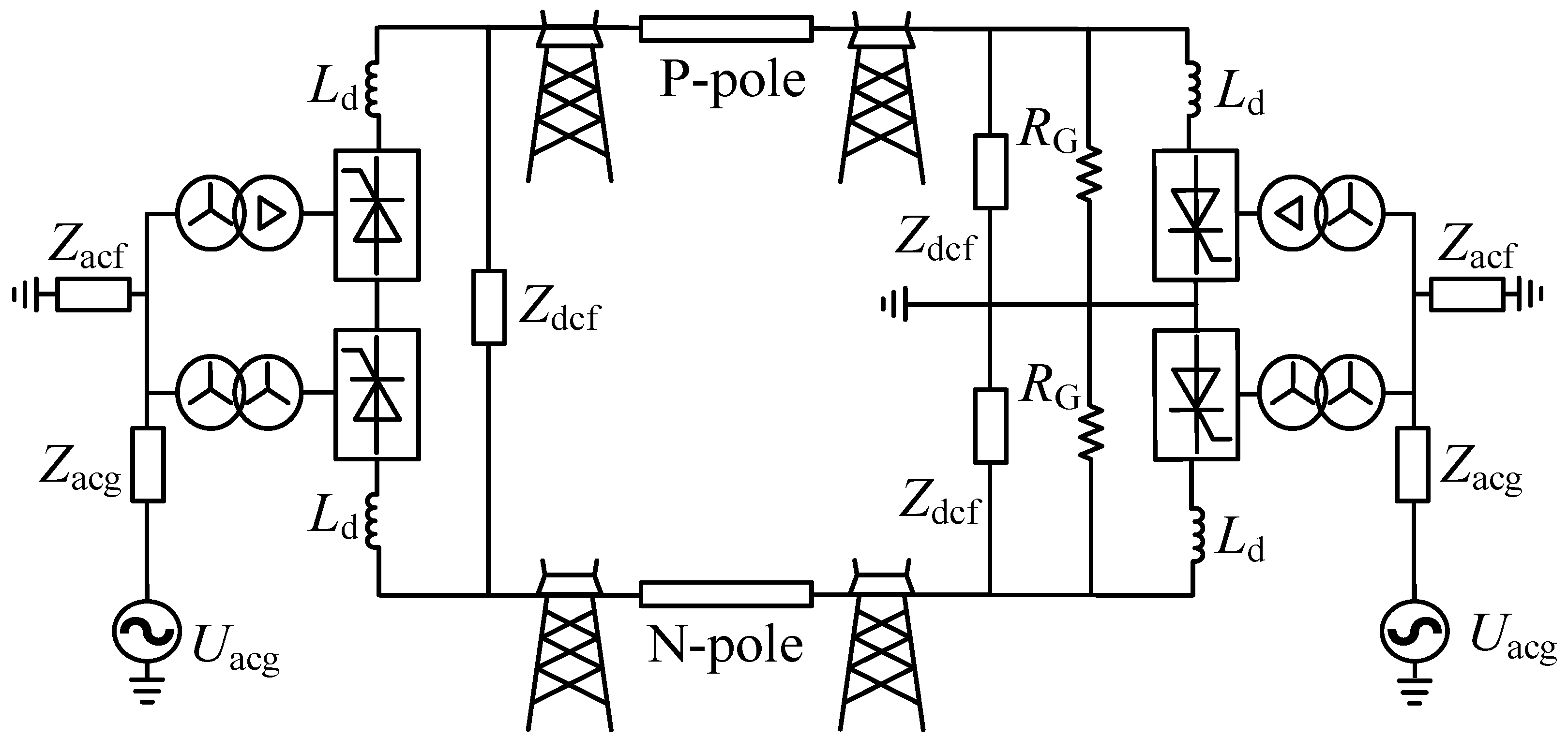
The current mainstream HVDC technology is a line-commutated converter-based HVDC (LCC-HVDC) and voltage source converter-based HVDC (VSC-HVDC). The advantage of a VSC-HVDC is that it can flexibly control active and reactive power, and the harmonic content is small, but its disadvantage is that the transmission capacity is small. Therefore, at present, an LCC-HVDC with high maturity, low cost and large transmission capacity is still the main choice for HVDC projects [29]. The main DC connection of an HVDC transmission system with two bipolar ends includes a neutral ground mode at one bipolar end (symmetrical monopole), a neutral ground mode at both bipolar ends and a bipolar metal neutral line mode. The typical project of transforming an AC line to a DC line in Germany and the United Kingdom adopts the symmetrical unipolar connection method with good economy and simple configuration. The topology of a symmetrical unipolar HVDC transmission system is shown in Figure 1. A symmetrical unipolar LCC-HVDC system rectifier side neutral point is not grounded, an inverter side converter neutral point is grounded and the two pole is grounded by a large resistance to maintain positive and negative voltage balance.
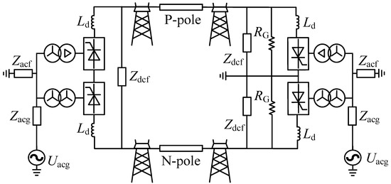
Figure 1.
Topology of the symmetric unipolar LCC-HVDC system.
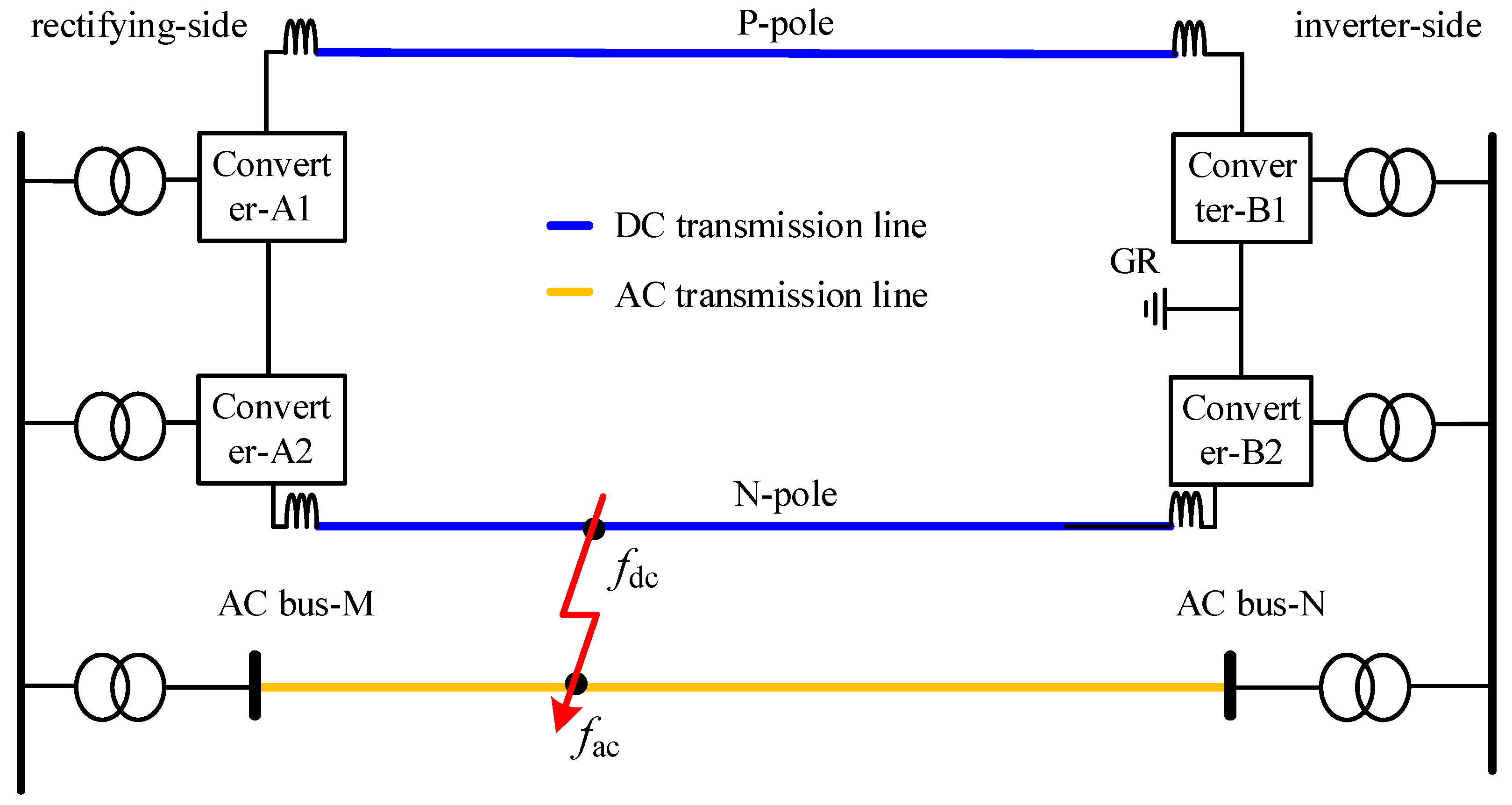
When the AC transmission lines in the transmission channel are transformed into HVDC lines, the AC and DC transmission lines are arranged and crossed closely with each other. At this time, the occurrence of intersystem faults increased. In this paper, the faults occurring in DC or AC systems are classified as non-intersystem faults, and the faults occurring between AC and DC are classified as intersystem faults. Taking the parallel DC and AC transmission lines in Figure 2 as an example, when intersystem faults occur, the AC/DC system has direct electrical coupling through the fault point and the fault point . During a fault transient, the transient characteristics of AC and DC systems can no longer be analyzed separately. New electrical features may pose challenges to the adaptability of traditional protection.
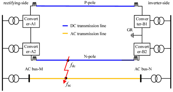
Figure 2.
Diagram of AC/DC intersystem faults.
2.2. HVDC Main Protection Configuration
Traveling wave protection [16] is the main protection of HVDC lines, which can respond to the fault within a few milliseconds, and the existing HVDC projects generally adopt this configuration. It is specified that the converter to the line is in the positive direction, and the fault judgment is carried out by constructing the reverse traveling wave [30] :
where and are the fault components of voltage and current at the protection point, respectively, and is the wave impedance of the transmission line.
Then, common-mode and difference-mode inverse traveling waves are constructed as follows:
Among them, and are common mode and differential mode inverse traveling waves, respectively, and are common mode and differential mode components of voltage, respectively, and are common mode and differential mode components of current, respectively, and and are common mode and differential mode wave impedances, respectively.
The common-mode components and differential-mode components of the positive and negative poles are calculated as follows:
The traveling wave protection criteria of the positive and negative poles are set as
where is the rate of change of the common-mode component, is the threshold value of the common mode change rate, and are the threshold values of the absolute values of the common mode and differential mode, respectively, and and are the polarity of the corresponding modulus.
2.3. Adaptability of HVDC Main Protection in Intersystem Fault Scenario
Taking the rectifier side of DC in Figure 2 as the observation point, the pole-phase fault occurred near the rectifier side, and its equivalent circuit is shown in Figure 3.
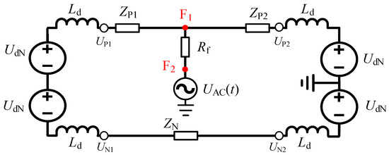
Figure 3.
Equivalent circuit for intersystem faults.
According to Figure 3, when a pole-phase fault occurs, the voltage fault components are expressed as
where and are the measured positive and negative voltages on the rectifier side, respectively. and are the equivalent voltage on the AC side and system-rated voltage.
If the non-intersystem faults occur at the same position, the voltage fault components are expressed as
In the process of calculating the differential-mode components, the in Equations (6) and (7) can be cancelled out, and can be obtained.
The common-mode voltage expression of the two fault types is
Compared with , the has an extra , which needs further discussion.
The common-mode current component is equal to , and the inverse traveling wave expression of the two fault types is
where is the fundamental frequency equivalent impedance behind the rectifier side. According to the engineering parameters, . Since is of the order of hundreds, the second term in the is the dominant factor.
Under the influence of the DC reactor , the voltage variation on the non-fault pole is smaller than that of the fault pole. When the P-pole and the N-pole are grounded, and , respectively. However, in the intersystem fault scenario, is significantly affected by , which no longer conforms to the above rules, and there is the possibility of incorrect tripping and protection failure.
3. New Protection Scheme of HPOTLs
3.1. Analysis of Current Characteristics in the Intersystem Fault Scenario
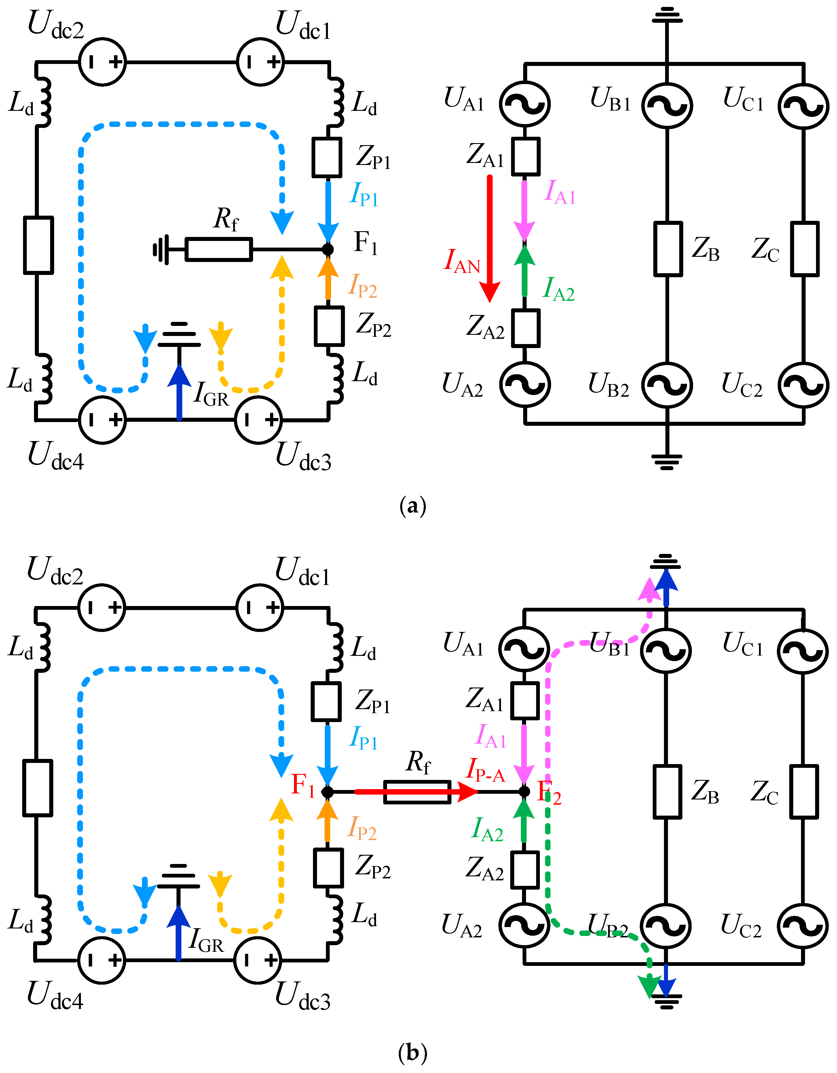
According to the research conclusion in the literature [11], among the various types of intersystem faults, a pole-phase intersystem can be identified as most critical with respect to protection. Therefore, taking the typical pole-phase intersystem (P-pole-to-A-phase fault) as an example, the current characteristics of AC and DC lines are analyzed. The current distribution of a DC single-pole ground fault and an intersystem fault is shown in Figure 4, and the is current flowing through the DC neutral point.
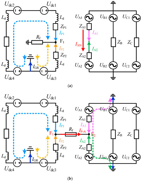
Figure 4.
Fault equivalent circuit. (a) DC single-pole ground fault. (b) Pole-phase fault.
As shown in Figure 4a, when the DC ground fault occurs, the current on both sides of the P-pole is and . Obviously, since and are in different circuits, the existence of is not equal to . At this time, the load current flows through both sides of AC phase-A, and the waveform of is the fault transient oscillation mode, while the waveform of is the fundamental frequency sine wave, and there is a big difference between the two waveforms.
When an intersystem fault occurs, as shown in Figure 4b, the following current relationship can be obtained:
where represents the current flowing from fault point to , and and are the AC side currents.
At this time, the fault components of and only have the amplitude difference generated by circuit shunt. In short, in the intersystem fault scenario, the waveform similarity between DC line current and AC line current is enhanced, which can be used to construct intersystem fault identification criteria.
3.2. Intersystem Fault Criterion Based on Current Similarity
The Hausdorff distance defines the distance between two sets in the same space and is used to describe the maximum degree of mismatch between the two sets as a whole. The smaller the Hausdorff distance is, the higher the degree of similarity between the two sets as a whole. If there exists set and set , then the Hausdorff distance between the two sets is expressed as
where the and are as follows:
where, the represents the distance between point a and point b.
In order to construct the criterion based on similarity, the fault component data of and are defined as and , respectively.
The characteristic quantities and are defined as
where the and are the load currents of the DC transmission line and the AC transmission line, respectively.
After and are normalized, and are obtained. Intersystem fault identification criteria based on current similarity are as follows:
where is the Hausdorff distance result of and substituted into Equation (11), which is used to characterize the similarity of currents on both sides. is the threshold value of current similarity. The setting principle of the protection threshold is to avoid the fault scenario that is most unfavorable to protection. In this paper, it is manifested as the non-intersystem fault at the near-area. When applied to different AC and DC power systems, the impact of system parameter differences on the selection of threshold values and the suggestions for threshold adjustment are summarized as follows: (a) Distributed capacitors will weaken the similarity of two groups of current waveforms in fault scenarios between systems. Since the size of distributed capacitors is positively correlated with the length of the lines, it is considered to raise the threshold value when the line length is longer. (b) The size of the DC reactor will affect the traveling wave reflection in the early stage of failure, and when the value of the reactor is reduced, the threshold value can be lowered. (c) The rated voltage of the AC/DC system will affect the initial fault state. When the difference between the two rated voltages is larger, the waveform difference is larger, and a higher threshold value should be selected; otherwise, a smaller threshold value is selected.
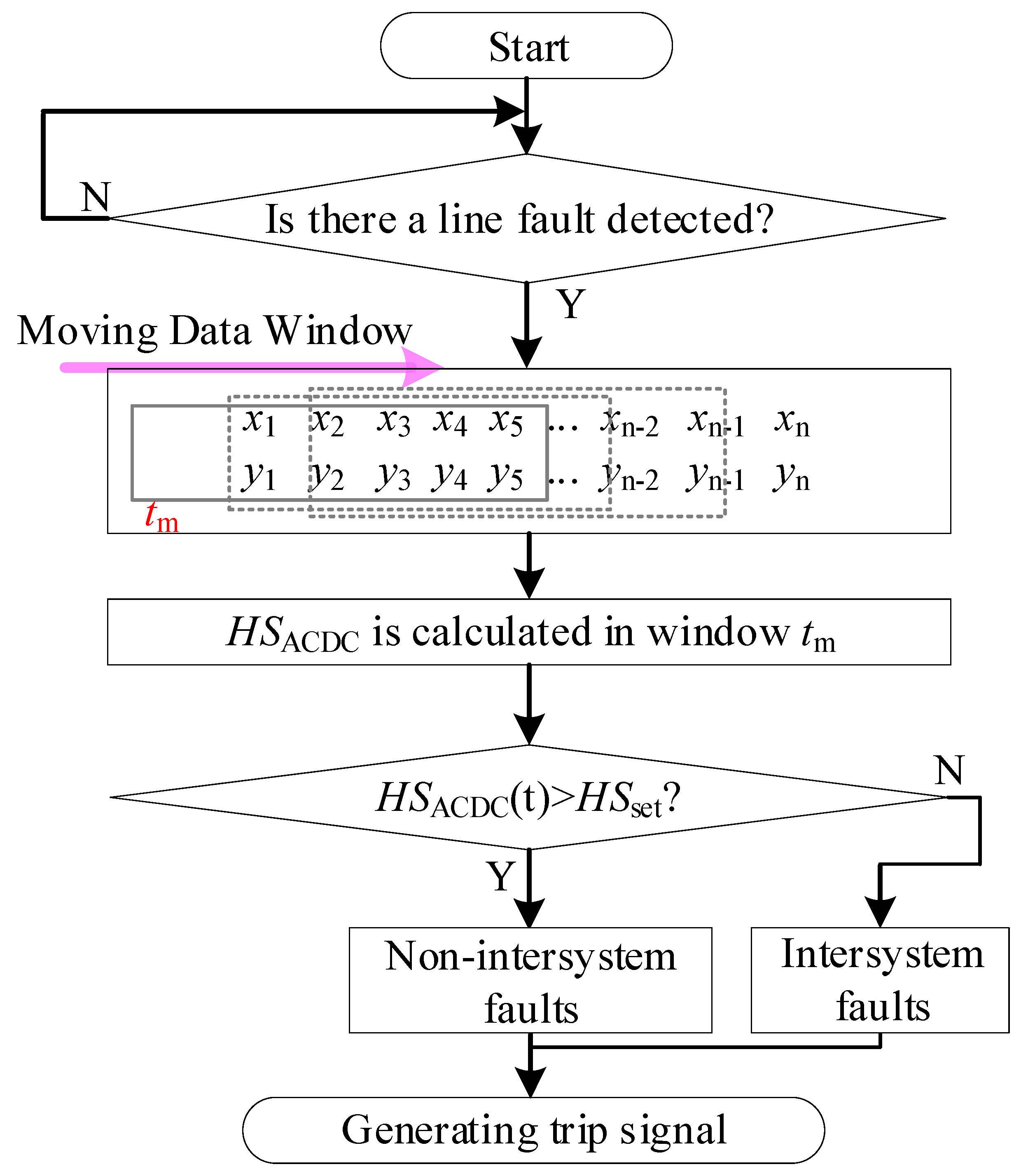
The protection time window is . After the fault time is located, the data 1 ms before the fault and 4 ms after the fault are intercepted for fault identification. The flow of the protection scheme is shown in Figure 5.
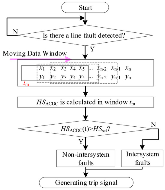
Figure 5.
Protection scheme flow chart.
4. Experimental Results and Analysis
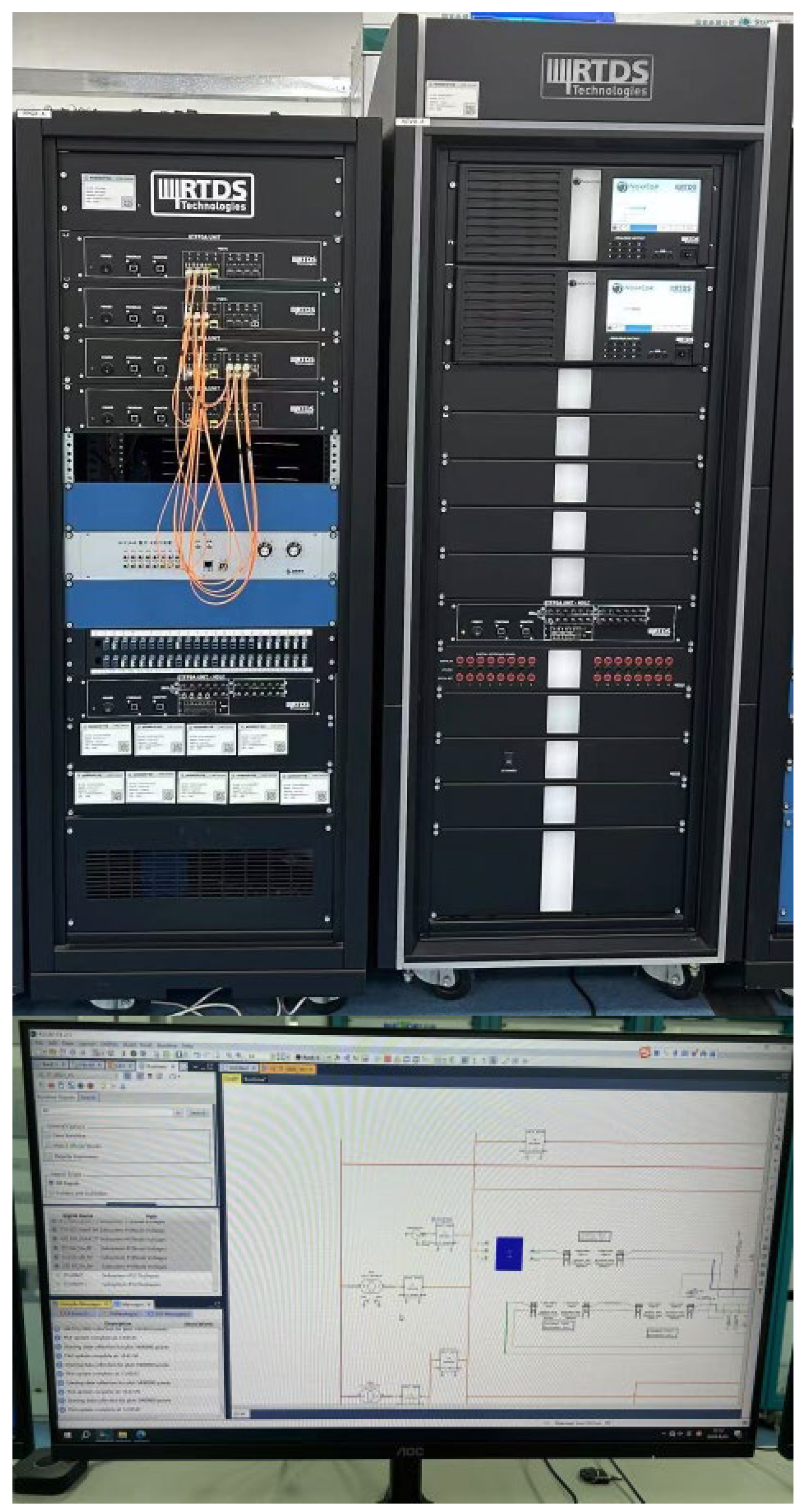
The build of the AC/DC hybrid overhead line system on the RTDS platform is shown in Figure 6, and Table 1 lists the system parameters. The protection performance is tested in non-intersystem fault and intersystem fault scenarios.
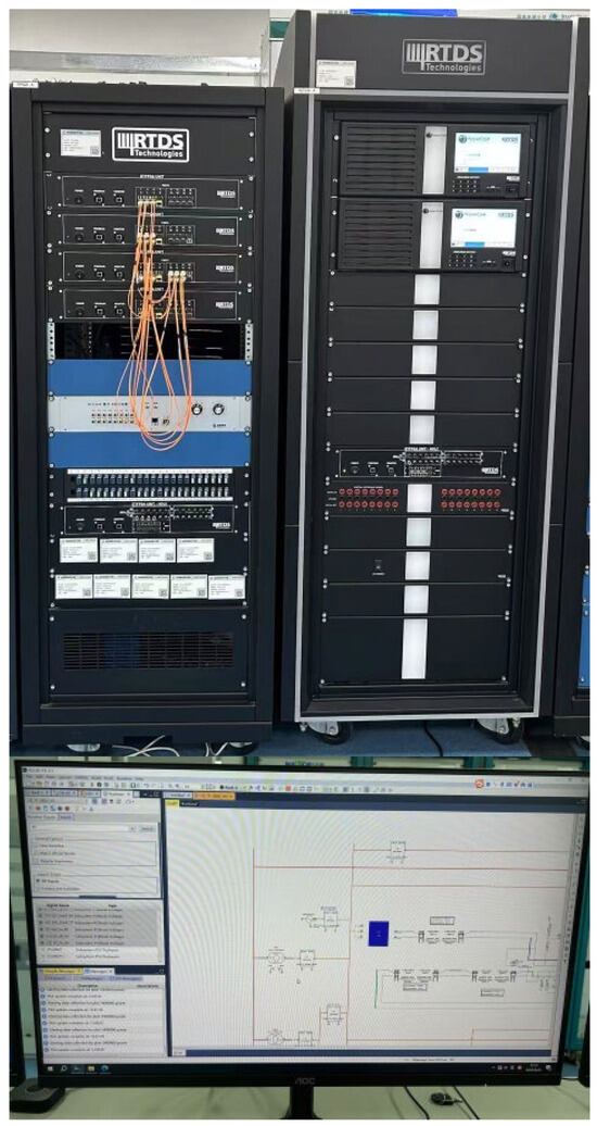
Figure 6.
RTDS platform.

Table 1.
System parameters.
4.1. Protection Test in Case of Non-Intersystem Fault
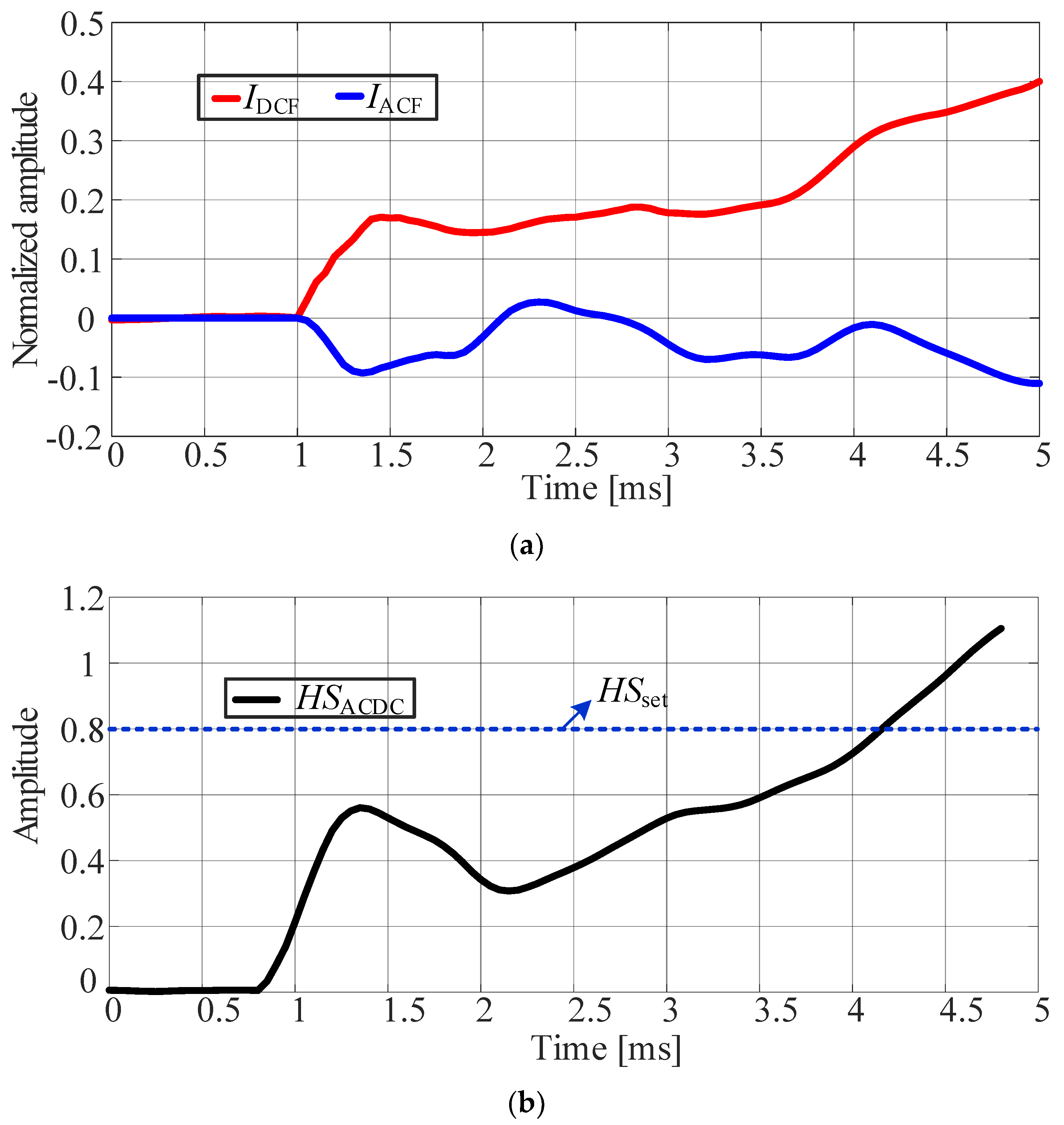
The test results of protection for when a metallic ground fault occurs at the head end of the DC line are shown in Figure 7.
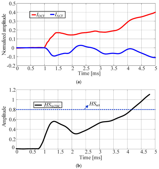
Figure 7.
Non-intersystem fault scenario on the DC side. (a) Current template diagram. (b) Current matching degree.
As shown in Figure 7, when the DC transmission line ground fault occurs, the waveform trends of and are opposite, and the maximum exceeds 1.1. The test results of protection for when a metallic ground fault occurs at the head end of the AC transmission line are shown in Figure 8, and the phase angle at the time of the fault is .

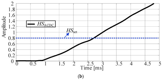
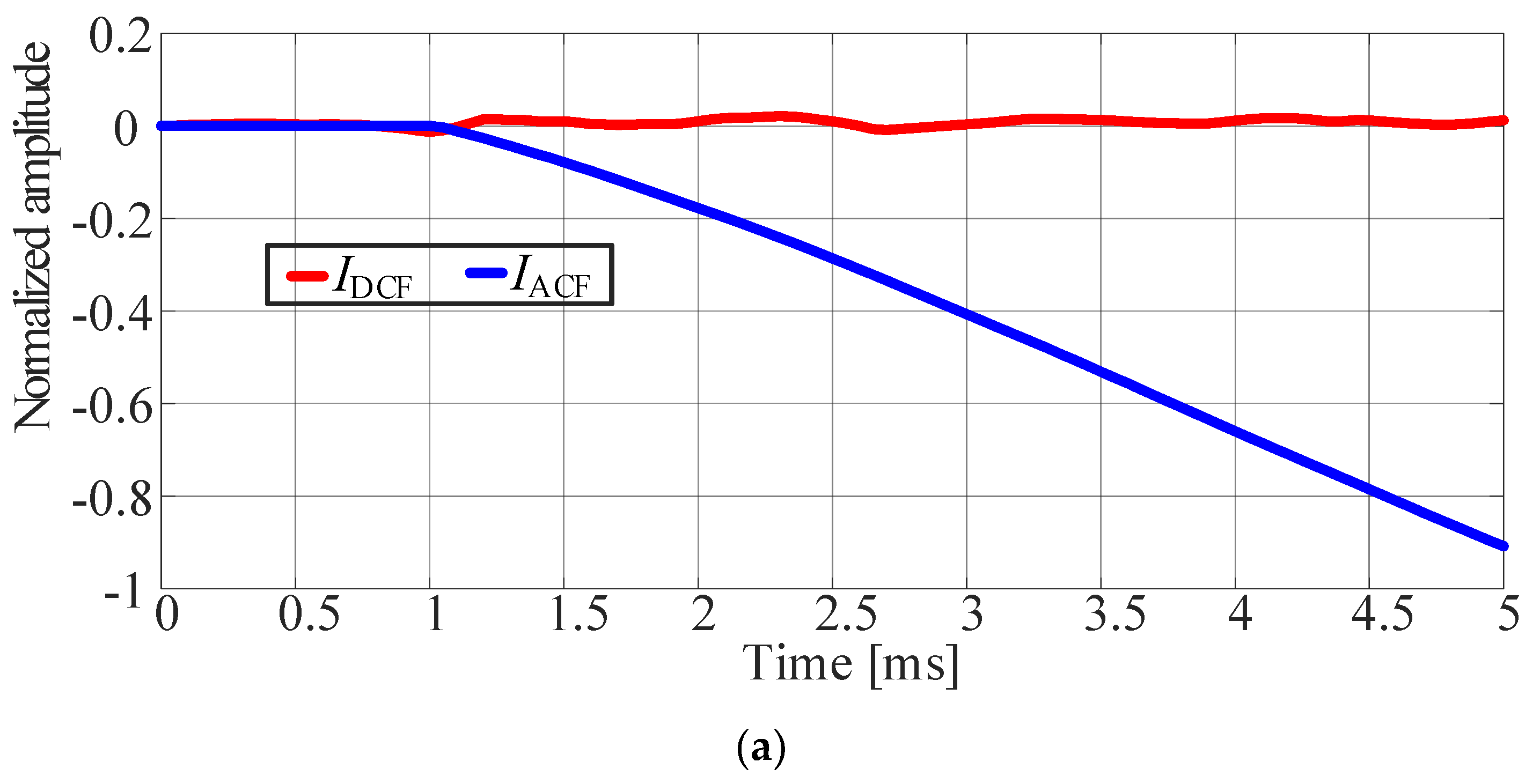
Figure 8.
Non-intersystem fault scenario on the AC side. (a) Current template diagram. (b) Current matching degree.
The change amplitude of is small, as shown in Figure 8, while continues to decline, and the maximum is about 2.
4.2. Protection Test in Case of Intersystem Fault
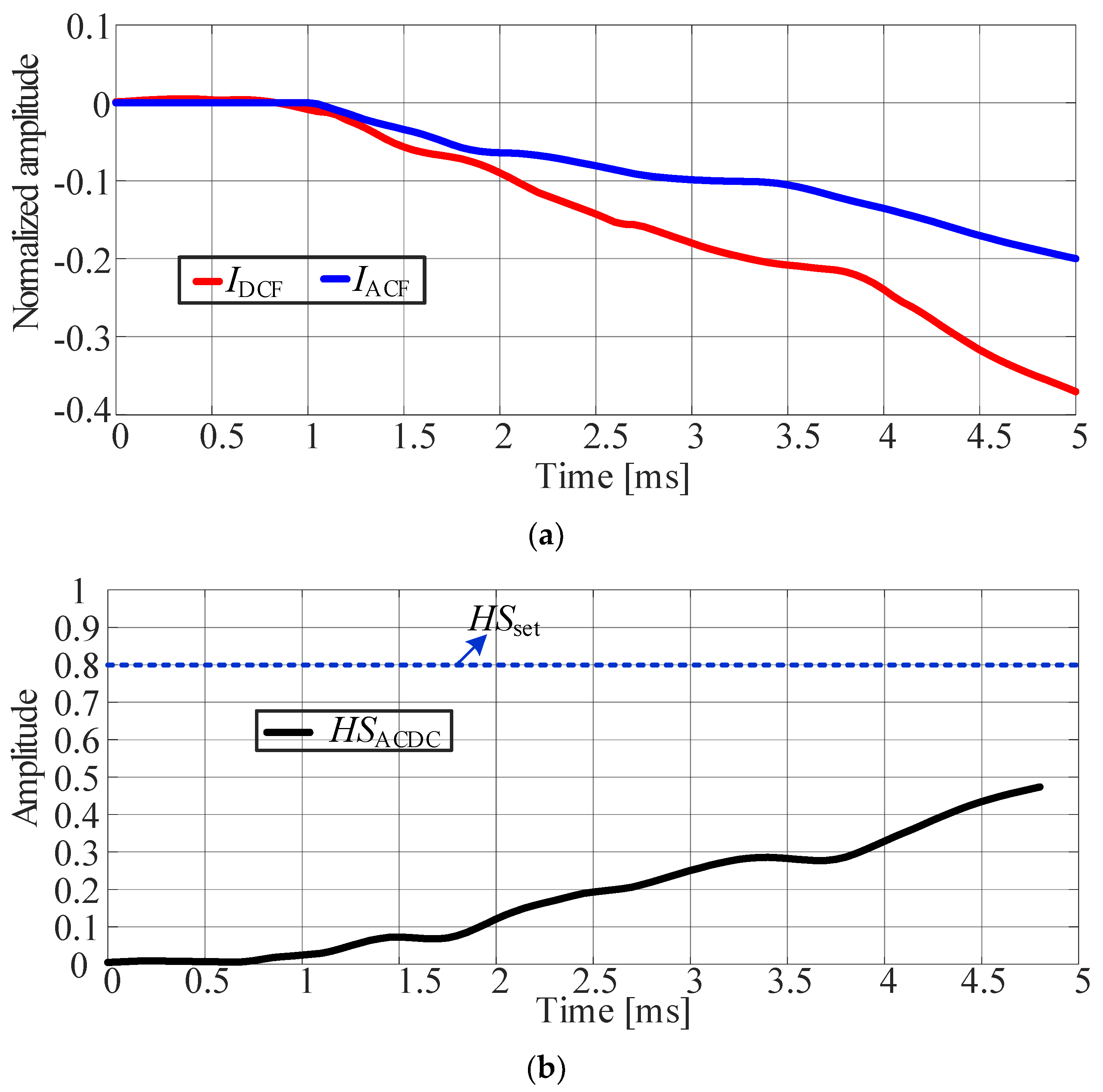
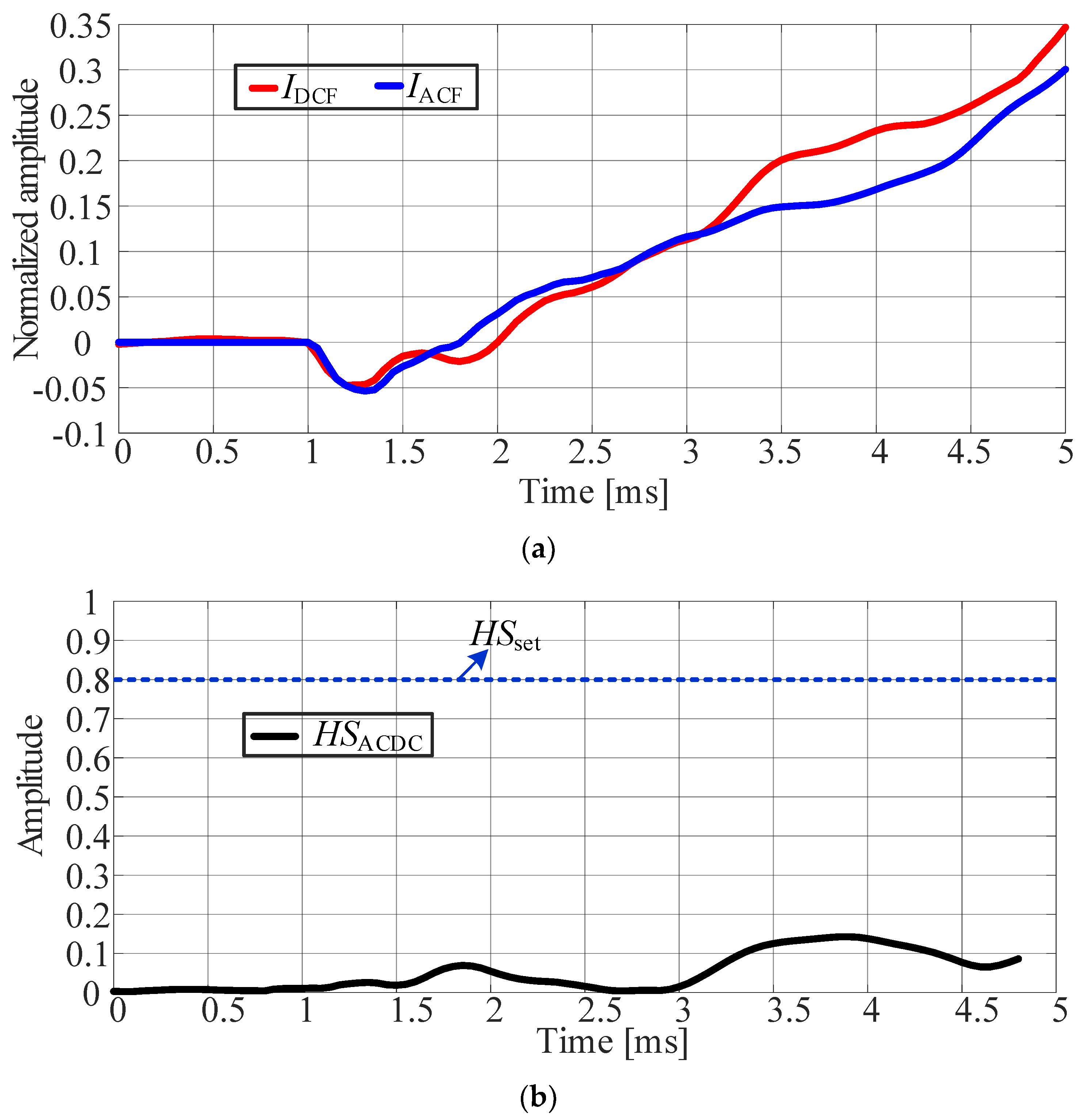
The amplitude fluctuation of and is relatively small under the pole-phase fault, which is shown in Figure 9, and they change according to the same trend, and the maximum value of is less than 0.5. When the initial fault phase angle is changed, the result is obtained when , as shown in Figure 10.

Figure 9.
Pole-phase fault at the head of the transmission line (). (a) Current template diagram. (b) Current matching degree.
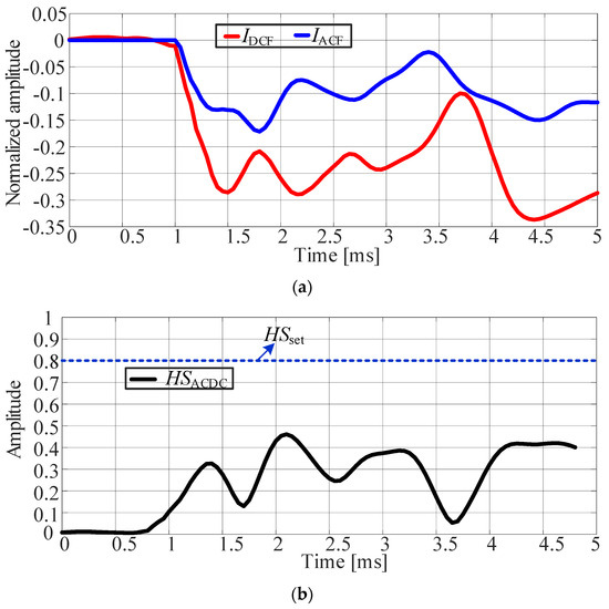
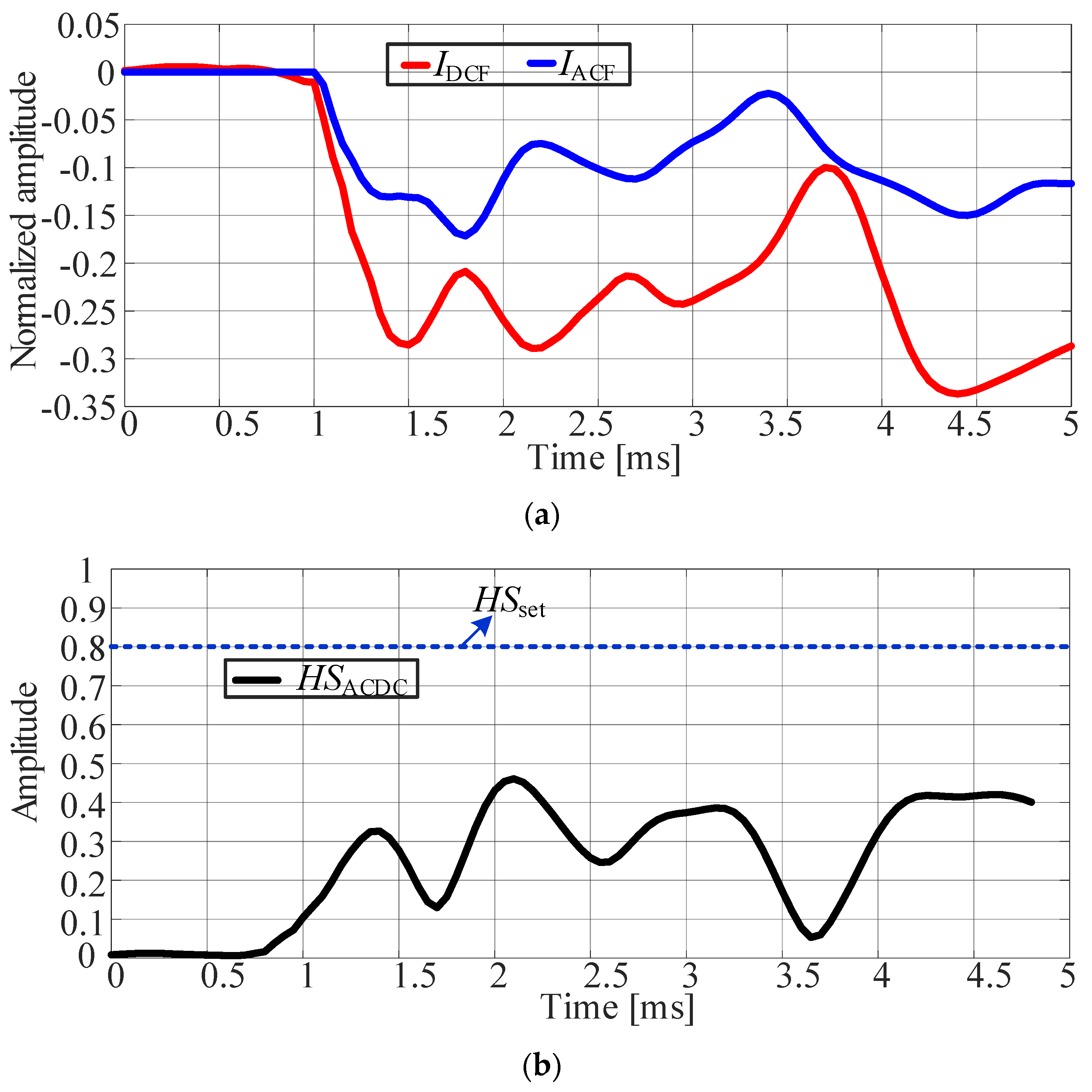
Figure 10.
Pole-phase fault at the head of the transmission line (). (a) Current template diagram. (b) Current matching degree.
In the fault scenario in which , the waveforms of and fluctuate greatly, but the trend change is similar, and the maximum is not more than 0.5. Comparing Figure 9 and Figure 10, it can be seen that the protection performance is not affected by the initial fault phase angle. For different fault phases, the maximum value of in the protection window is relatively close.
At the end of the line fault, the waveforms of and also mutate (shown in Figure 11), but the matching degree of the two waveforms is very high, and the maximum value of is less than 0.2. The above results show that can effectively distinguish a intersystem fault from a non-intersystem fault. In addition, the threshold value of protection still has a certain margin. Additionally, comparing Figure 10 and Figure 11, it can be seen that when the initial fault phase angle is the same, the farther the fault location is from the protection, and the smaller the value of in the protection window. This shows that the protection has better reliability against terminal faults.
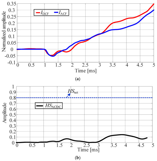
Figure 11.
Pole-phase fault at the end of the transmission line (). (a) Current template diagram. (b) Current matching degree.
4.3. Comparative Analysis
HVDC transmission systems are usually configured with AC/DC intersystem protection. The existing protection criteria include two zones as follows:
where and represent the 50 Hz component of DC voltage and DC current, respectively, and and are the thresholds of protection Zone I and protection Zone II, respectively.
The delay time of protection Zone I is 10 ms. To ensure reliability, the threshold should be raised to avoid some disturbances. The threshold is generally set to more than 0.25 pu, and the value is 0.3 pu in this paper. Protection Zone II is more sensitive and therefore has a lower threshold value of 0.1 pu, but the delay time of Zone II is up to 100 ms. The existing 50 Hz component-based protection performance is tested in the intersystem fault scenario shown in Figure 12.
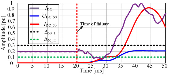
Figure 12.
Pole-phase fault at the head of the transmission line.
As can be seen from Figure 12, the time it takes for the criterion of Zone II to be established is about 10 ms after the fault, and with its delay, its exit time takes 110 ms. The time it takes for the criterion of Zone I to be established is about 17 ms after the fault, and with its delay, its exit time takes 27 ms. The above results show that the response time of the existing protection is more than 25 ms even for more serious intersystem faults, and more than 100 ms for minor intersystem faults. Compared with the existing protection, the proposed protection can significantly improve the fault response speed.
5. Conclusions
The intersystem fault easily occurs in the limited transmission channel where AC/DC hybrid overhead lines (HPOTLs) are set up in the same tower. Focusing on intersystem faults, this paper proposes a protection scheme that can identify intersystem faults and non-intersystem faults. Through simulation experiments, the following conclusions were obtained: (a) The waveforms of the fault components of AC and DC current on the same side are similar to each other. (b) The performance of the proposed protection is not affected by the initial fault phase angle; the farther the fault point is, the better the performance, and the response ability to the end fault is good. (c) The proposed protection only needs to set a simple Hausdorff distance threshold to identify an intersystem fault, and has good adaptability to intersystem fault scenarios. (d) The proposed scheme only needs 4 ms of data after a fault, which can meet the operation speed requirement of DC main protection.
Based on the work undertaken in this paper, the prospects for the protection scheme of an AC/DC intersystem fault in the future are as follows:
(a) The use of mathematical formulas to relate power system parameters to Hausdorff distances is a worthy study, and this will help demonstrate the adaptability of the method to different power systems. (b) There is a need to study protection that uses only one end of a separate system, which is completely independent of communication and can be better adapted to longer transmission lines.
Author Contributions
Conceptualization, Y.T. and X.K.; methodology, Y.T.; software, X.K.; valida- tion, C.W. and J.Z.; formal analysis, Z.B.; investigation, J.L.; resources, S.X. and Y.T.; data curation, Y.T.; writing—original draft preparation, J.Z.; writing—review and editing, J.L.; supervision, C.W.; project administration, J.Z. All authors have read and agreed to the published version of the manuscript.
Funding
Project Supported by State Grid Jiangsu Electric Power Co., Ltd. Technology Project (No. J2024022).
Institutional Review Board Statement
Not applicable.
Informed Consent Statement
Not applicable.
Data Availability Statement
The data are available in a publicly accessible repository.
Conflicts of Interest
All Authors were employed by the Electric Power Research Institute of Jiangsu Electric Power Co., Ltd. The remaining authors declare that the research was conducted in the absence of any commercial or financial relationships that could be construed as a potential conflict of interest.
References
- Liu, L.-Q.; Liu, C.-X. VSCs-HVDC may improve the electrical grid architecture in future world. Renew. Sust. Energy Rev. 2016, 62, 1162. [Google Scholar] [CrossRef]
- Dargahi, V.; Sadigh, A.K.; Pahlavani, M.R.A.; Shoulaie, A. DC (direct current) voltage source reduction in stacked multicell converter based energy systems. Energy 2012, 46, 649. [Google Scholar] [CrossRef]
- Yang, Y.; Zhang, S.; Xiao, Y. Optimal design of distributed energy resource systems coupled with energy distribution networks. Energy 2015, 85, 433. [Google Scholar] [CrossRef]
- Humpert, C. Long distance transmission systems for the future electricity supply—Analysis of possibilities and restrictions. Energy 2012, 48, 278. [Google Scholar] [CrossRef]
- Ponitka, J.; Boettner, S. Challenges of future energy landscapes in Germany—A nature conservation perspective. Energy Sustain. Soc. 2020, 10, 17. [Google Scholar] [CrossRef]
- Mahfouz, M.M.; El-Sayed, M.A. One-end protection algorithm for offshore wind farm HVDC transmission based on travelling waves and cross-alienation. Elec. Power Syst. Res. 2020, 185, 106355. [Google Scholar] [CrossRef]
- Pipelzadeh, Y.; Chaudhuri, B.; Green, T.C.; Adapa, R. Role of western HVDC link in stability of future Great Britain (GB) transmission system. In Proceedings of the 2015 IEEE Power & Energy Society General Meeting, Denver, CO, USA, 26–30 July 2015. [Google Scholar] [CrossRef]
- Düllmann, P.; Klein, C.; Winter, P.; Köhler, H.; Steglich, M.; Teuwsen, J.; Leterme, W. Preventive DC-side decoupling: A system integrity protection scheme to limit the impact of DC faults in offshore multi-terminal HVDC systems. IET Gener. Transm. Distrib. 2024, 18, 3801–3816. [Google Scholar] [CrossRef]
- Qiao, J.; Zou, J.; Zhang, J.; Lu, Y.; Lee, J.; Ju, M.-N. Space-time pattern of ion flow under AC/DC hybrid overhead lines and its application. IEEE Trans. Power Deliv. 2017, 33, 2226. [Google Scholar] [CrossRef]
- Yang, Y.; Lu, J.; Lei, Y. A calculation method for the hybrid electric field under UHVAC and UHVDC transmission lines in the same corridor. IEEE Trans. Power Deliv. 2010, 25, 1146. [Google Scholar] [CrossRef]
- Prommetta, J.; Schindler, J.; Jaeger, J.; Keil, T.; Butterer, C.; Ebner, G. Protection Coordination of AC/DC Intersystem Faults in Hybrid Transmission Grids. IEEE Trans. Power Deliv. 2020, 35, 2896. [Google Scholar] [CrossRef]
- Wang, X.; Kong, M. Transient characteristics and protection coordination strategy of hybrid AC/DC system based on modular multilevel converters under AC/DC transmission lines touching fault. Energy Rep. 2024, 11, 4213. [Google Scholar] [CrossRef]
- Ebner, G.; Döring, D.; Schettler, F.; Würflinger, K.; Zeller, M. Fault handling at hybrid high-voltage AC/DC transmission lines with VSC converters. IEEE Trans. Power Deliv. 2018, 33, 901. [Google Scholar] [CrossRef]
- Wang, W.; Li, B.; Li, B.; He, J.; Yao, B.; Liu, Y. Intersystem fault between MMC-HVDC and AC systems and its impact on DC/AC protection. IET Gener. Transm. Distrib. 2022, 16, 938. [Google Scholar] [CrossRef]
- Sun, Q.; Li, B.; He, J.; Li, Y. Measured Impedance and Threshold Value of Electrode Line Impedance Supervision Based Protection in HVDC Transmission System. J. Mod. Power Syst. Clean. Energy 2023, 11, 1294. [Google Scholar] [CrossRef]
- Zhang, Y.; Tai, N.; Xu, B. Fault Analysis and Traveling-Wave Protection Scheme for Bipolar HVDC Lines. IEEE Trans. Power Deliv. 2012, 27, 1583. [Google Scholar] [CrossRef]
- Liu, X.; Osman, A.H.; Malik, O.P. Hybrid Traveling Wave/Boundary Protection for Monopolar HVDC Line. IEEE Trans. Power Deliv. 2009, 24, 569. [Google Scholar] [CrossRef]
- Mirhosseini, S.S.; Jamali, S.; Popov, M. Non-unit protection method for long transmission lines in MTDC grids. IET Gener. Transmiss. Distrib. 2021, 15, 1674. [Google Scholar] [CrossRef]
- Zhang, C.; Huang, J.; Song, G.; Dong, X. Non-unitultra-high-speed line protection for multi-terminal hybrid LCC/MMC HVDC system and its ap-plication research. IEEE Trans. Power Del. 2021, 36, 2825. [Google Scholar] [CrossRef]
- Wang, D.; Hou, M. Travelling wave fault location algorithm for LCC-MMC-MTDC hybrid transmission system based on Hilbert-Huang transform. Int. J. Elect. Power Energy Syst. 2020, 121, 106125. [Google Scholar] [CrossRef]
- Huang, Q.; Zou, G.; Zhang, S.; Gao, H. A Pilot Protection Scheme of DC Lines for Multi-Terminal HVDC Grid. IEEE Trans. Power Del. 2019, 34, 1957. [Google Scholar] [CrossRef]
- Yang, Y.; Huang, C.; Xu, Q. A Fault Location Method Suitable for Low-Voltage DC Line. IEEE Trans. Power Deliv. 2019, 35, 194. [Google Scholar] [CrossRef]
- Adharapurapu, H.L.; Bhimasingu, R. A novel algorithm for improving the differential protection of power transmission system. Elec. Power Syst. Res. 2020, 181, 106183. [Google Scholar] [CrossRef]
- Hashemi, S.M.; Sanaye-Pasand, M. Current-Based Out-of-Step Detection Method to Enhance Line Differential Protection. IEEE Trans. Power Del. 2018, 34, 448. [Google Scholar] [CrossRef]
- Xu, Z.Y.; Du, Z.Q.; Ran, L.; Wu, Y.K.; Yang, Q.X.; He, J.L. A current differential relay for a 1000-kV UHV transmission line. IEEE Trans. Power Del. 2007, 22, 1392. [Google Scholar] [CrossRef]
- Ma, J.; Pei, X.; Ma, W.; Wang, Z. A new transmission line pilot differential protection principle using virtual impedance of fault component. Can. J. Elect. Comput. Eng. 2015, 38, 37. [Google Scholar] [CrossRef]
- Fayazi, M.; Saffarian, A.; Joorabian, M.; Monadi, M. An AI-based fault detection and classification method for hybrid parallel HVAC/HVDC overhead transmission lines. Elec. Power Syst. Res. 2024, 238, 111083. [Google Scholar] [CrossRef]
- Mehdi, A.; Hussain, A.; Song, J.-S.; Kim, C.-H. A robust unified data-driven protection scheme for hybrid AC/DC transmission lines. Elec. Power Syst. Res. 2024, 233, 110453. [Google Scholar] [CrossRef]
- Guo, C.; Zhang, Y.; Gole, A.; Zhao, C.; Gole, A. Analysis of dual-infeed HVDC with LCC-HVDC and VSC-HVDC. In Proceedings of the 2013 IEEE Power & Energy Society General Meeting, Vancouver, BC, Canada, 21–25 July 2013; IEEE: Piscataway, NJ, USA, 2013. [Google Scholar]
- Li, B.; Li, Y.; Li, B.; Chen, X.; Ji, L.; Hong, Q. A novel travelling-wave direction criterion for hybrid multi-terminal HVDC system. IET Gener. Transm. Distrib. 2024, 18, 3765–3776. [Google Scholar] [CrossRef]


Disclaimer/Publisher’s Note: The statements, opinions and data contained in all publications are solely those of the individual author(s) and contributor(s) and not of MDPI and/or the editor(s). MDPI and/or the editor(s) disclaim responsibility for any injury to people or property resulting from any ideas, methods, instructions or products referred to in the content. |
© 2025 by the authors. Licensee MDPI, Basel, Switzerland. This article is an open access article distributed under the terms and conditions of the Creative Commons Attribution (CC BY) license (https://creativecommons.org/licenses/by/4.0/).