Article

A Comparative Study of Methanol and Methane Combustion in a Gas Turbine Combustor

by
Jiashuo Cui
1,2,
Rongguo Yu
1,
Huishe Wang
1,2,*,
Yangen Wang
1 and
Jingze Tong
1
1
Institute of Engineering Thermophysics, Chinese Academy of Sciences, Beijing 100190, China
2
School of Aeronautics and Astronautics, University of Chinese Academy of Sciences, Beijing 100049, China
*
Author to whom correspondence should be addressed.
Energies 2025, 18(7), 1765; https://doi.org/10.3390/en18071765
Submission received: 6 March 2025 / Revised: 23 March 2025 / Accepted: 27 March 2025 / Published: 1 April 2025
(This article belongs to the Special Issue Advanced Combustion Technologies and Emission Control)

Abstract

:
To investigate the combustion and emission characteristics of a 20 MW gas turbine combustor following fuel replacement, this study employs numerical simulations to systematically compare the combustion performance of methanol and methane. The focus is on the influence mechanism of the fuel distribution ratio on NOx emissions. As a preliminary numerical investigation, this study aims to provide theoretical guidance for subsequent experimental research, with the results serving to define measurement points in experimental design. It is found that the value of NOx emission from methanol combustion is 40–78% of that of methane under all operating conditions, which is significantly lower than that of methane. And its low NOx emission range is significantly wider than that of methane (methanol: a pilot fuel ratio range of 1–12%; methane: a pilot fuel ratio range from 2 to 4%). Methanol reaches the lowest NOx emission (51.53 ppm) near the pilot fuel ratio of 2%, while methane reaches the lowest NOx emission (93 ppm) near the pilot fuel ratio of 4%. This difference is due to the oxygen content and low calorific value of methanol, which makes it easier to reduce the flame in the main combustion zone to the temperature that inhibits the generation of thermal NOx, so there is no need to allocate more fuel to the pilot to reduce the cooling pressure in the main combustion zone. In addition, the combustor efficiency of methanol is higher and less volatile (99.52–99.89%), which is slightly higher than that of methane (99.33–99.61%). The results show that methanol is suitable as a gas turbine fuel. Its performance in the gas turbine combustor is slightly better than that of methane, and NOx emission is significantly better than that of methane. The better performance of methanol provides greater flexibility for the design of gas turbine combustors and has great feasibility in engineering.

1. Introduction

As an efficient power generation system, gas turbines are widely used in electric power [1,2], aviation [3], and marine applications [4]. Its fast start–stop, high efficiency, and low emission characteristics make it a key equipment in modern energy systems [5,6,7]. However, nitrogen oxide (NOx) emissions from gas turbine combustion pose a serious threat to the environment and human health [8,9]. NOx is a primary precursor of photochemical smog and acid rain, and it also plays a significant role in ozone layer depletion. In recent years, with the increasingly stringent global environmental regulations, reducing NOx emissions from gas turbines has become a research hotspot [10,11]. Common low-NOx gas turbine technologies include water/steam injection, dry low emission (DLE) combustion, and selective non-catalytic reduction (SNCR) [12,13,14,15]. However, these technologies typically require integration during the design phase and are challenging to implement directly in existing combustors.
For the centrally staged gas turbine combustor, which is the focus of this study, two approaches can be taken to reduce NOx emissions with the least amount of retrofitting: pilot fuel ratio (PFR) optimisation and fuel replacement. The PFR is a critical parameter in gas turbine combustor design, and it is defined as the mass flow ratio of pilot fuel to main fuel [16]. In a centrally staged gas turbine combustor, the fuel is typically divided into two parts: one part enters the combustor through the main fuel nozzle to form the main combustion zone; the other part enters through the pilot fuel nozzle to form the pilot flame. The main function of the pilot flame is to stabilise the combustion process, especially under low-load or extreme conditions, to ensure the reliable ignition and flame stability of the combustor. However, the pilot flame is part of the diffusion flame, and its high-temperature zone will reduce the efficiency of the combustor, worsen the outlet temperature distribution, and enhance the formation of NOx [17]. Therefore, a PFR that is too large or too small will have a negative effect on combustor performance. Additionally, substituting fuels with superior combustion characteristics is an effective strategy for reducing NOx emissions. In this study, methanol was selected as an alternative fuel. Methanol molecules contain oxygen, leading to a lower adiabatic flame temperature and significantly inhibiting NOx formation.
Studies have demonstrated that optimising the PFR can effectively reduce NOx emissions. Zhang et al. [18] investigated the effect of fuel distribution methods on NOx emissions in a centrally staged gas turbine combustor using three-dimensional numerical simulations. The results show that the optimised fuel distribution can significantly reduce NOx emissions, especially at high loads. Zong et al. [19] pointed out in the study that through the experimental and numerical simulation analysis of a 100 kW micro gas turbine with a double annular swirler (DAS) burning methane, it was found that the PFR has a significant effect on NOx emissions: With the increase in the PFR, NOx emissions show a trend of decreasing first and then increasing and reach the lowest value near 11%. In addition, Zong et al. [20] further explored the regulation of the PFR on the flow field and pollutant distribution in the combustor. The study showed that when the PFR was 9.0%, the NOx contribution of the pilot flame accounted for 17.4% of the total emissions.
In addition to the PFR, the use of methanol has also been considered as an effective means of reducing the NOx emissions from gas turbines. Glaude et al. [21] numerically studied the combustion characteristics of various fuels under the condition of a gas turbine combustor. The results show that the flame temperature of methanol combustion is significantly lower than that of traditional fuels, thus effectively inhibiting the generation of thermal NOx. In addition, the study also points out that methanol as a gas turbine fuel only needs limited modification of the combustor, which has high engineering application feasibility. Levy et al. [22] used the CHEMKIN code (one-dimensional reactor model) and the ANSYS code for numerical calculation. The study combines a laboratory-scale swirl-stabilised combustor model for methanol combustion experiments, which verifies the feasibility of the numerical method in the study of methanol combustion in the combustor. However, the application of methanol in specific gas turbines remains in the preliminary stage. Von KleinSmid et al. [23] conducted a 523 h methanol combustion test on a 26 MW gas turbine, and the results showed that methanol is an excellent gas turbine fuel. Smith et al. [24] conducted a comparative test of methanol and natural gas for an 800 kW Saturn gas turbine and carried out a small-scale bench test of an advanced burner. The results show that the methanol fuel reduces NOx emissions by 63% at the design point. Chudnovsky et al. [25,26,27] conducted a full-scale methanol combustion test on a 50 MWe FT4C TWIN PAC gas turbine designed by Pratt & Whitney. Combined with simulations, they pointed out that the excess air volume is an important parameter for regulating the emission of pollutants at the outlet. The results show that methanol combustion significantly reduces NOx, SO2, and particulate emissions through the transformation of low-cost fuel systems, in which NOx emissions are reduced by more than 75% to 75 mg/dNm3 (15% O2). Studies have shown that methanol is an economical and environmentally friendly alternative fuel, which can be well adapted to gas turbine combustion and improve its performance. Existing research has carried out extensive and in-depth studies of gas turbine combustors using a variety of methods, including simulations alone, experiments alone, and simulations combined with experiments. These studies not only explored the performance of gas turbines burning methanol but also analysed the basic characteristics of methanol combustion, such as flame propagation speed and combustion stability. This series of studies has shown that both numerical simulations and experimental methods have important value in the study of gas turbine combustors, and the feasibility and credibility of the results have been fully verified.
In terms of the scope, methanol is not a widely used gas turbine fuel. Most of the existing studies focus on verifying its overall performance and are mainly based on experiments. In contrast, methane is the most widely used gas turbine fuel. The scope of research ranges from the overall performance to the details of the flame structure and flow field in the combustor. The numerical simulations and experiments are well combined, and the research system is perfect. From the perspective of combustion mechanisms, researchers have developed numerous methane combustion mechanisms. Ever since Dr. W. Tsang [28] established a comprehensive chemical database, significant progress has also been made in the study of methanol combustion mechanisms. The existing mechanisms of the two fuels can meet the needs of engineering practices. Egolfopoulos et al. [29] pointed out that the carbon–oxygen bond in the methanol molecule makes its oxidation mechanism completely different from that of methane. This property has a direct impact on its combustion characteristics, in particular the adiabatic flame temperature, which is also the focus of this study.
As mentioned above, it is evident that there are several gaps in methanol combustion research. First, due to its limited application range and relatively low demand, detailed studies on methanol fuel are scarce. Among them, the influence mechanism of PFR on NOx emissions in methanol combustion has not been systematically discussed. Second, the oxygen-containing nature of methanol results in a significantly lower adiabatic flame temperature compared to methane, which plays a crucial role in inhibiting NOx formation. However, its specific influence mechanism requires further analysis.
Based on the aforementioned research gaps, this study aims to systematically investigate the combustion characteristics of methanol fuel in a gas turbine combustor through numerical simulations, focusing on the influence mechanism of PFR on NOx emissions and comparing it with methane combustion. The specific research objectives include the following: analysing the flow field, temperature field, and NOx emission characteristics of methanol combustion; revealing the influence mechanism of PFR on NOx generation; comparing the performance difference between methanol and methane combustion; and quantitatively evaluating the potential of methanol as a gas turbine fuel. This study is a preliminary investigation, providing the groundwork for subsequent experimental research.
The significance of this study is to reveal the correlation mechanism between PFR and NOx generation in methanol combustion through numerical simulations, thereby addressing the gaps in existing research. The performance of a 20 MW gas turbine combustor was quantitatively compared when methanol and methane were used as fuels, respectively.

2. Numerical Methods

In this study, a numerical simulation method was employed to investigate the combustion performance of methanol and methane in a gas turbine combustor. Numerical methods are based on computational fluid dynamics (CFD) techniques, which are widely used in combustion and gas turbine research. The governing equations, combustion model, turbulence model, NOx model, and numerical settings used in this study are detailed in the following sections.

2.1. Governing Equations

The combustion process in a gas turbine combustor involves complex interactions between fluid flow, heat transfer, and chemical reactions. For accuracy and computational efficiency, the three-dimensional Reynolds-averaged Navier–Stokes (RANS) equations are used as the governing equation in this study [30,31]. The commercial CFD software Ansys Fluent 2021 was used for the simulations.
Continuity equation:
ρ t + ( ρ u ) = 0
Momentum equation:
( ρ u ) t + ( ρ u u ) = p + τ + ρ g
Energy equation:
( ρ E ) t + ( ρ u E ) = ( k T ) + ( u τ ) + S h
Species transportation equation:
( ρ Y i ) t + ( ρ u Y i ) = ( ρ D i Y i ) + ω ˙ i
where ρ is the fluid density, t is the time, u is the velocity vector, p is the pressure, τ is the stress tensor, g is the gravitational acceleration vector, E is the total energy, k is the thermal conductivity, T is the temperature, S h is the chemical reaction source term, Y i is the mass fraction of component i , D i is the diffusion coefficient of component i , and ω ˙ i is the reaction rate of component i .
The solver algorithm employs the coupled method to significantly enhance the convergence speed by coupling the momentum and energy equations, which is particularly useful for high-speed flow and combustion simulations. The time scale factor is set to 0.1, and most of the equations mentioned are spatially discretised using a second-order upwind scheme to enhance the ability to capture flow field details.

2.2. Tubulence Model, Combustion Model, and NOx Model

Turbulence plays a crucial role in the combustion process, particularly in gas turbine combustors where the Reynolds number is usually high. To simulate turbulent flow, the Realisable k-ε model was employed in this study [32,33]. The model can accurately capture the strong rotation and separation effects in the flow, which are typical in gas turbine combustors. According to the Ansys Fluent Theory Guide, the constants of the model are C = 1.44, C2 = 1.9, σk = 1.0, and σε = 1.2 [34].
The combustion process is simulated using the Eddy Dissipation Model, which is suitable for modelling rotating flames in gas turbine combustors [35,36,37]. The Eddy Dissipation Model assumes that the reaction rate is governed by the turbulent mixing of the reactants rather than chemical kinetics.
The reaction rate of component i is given by the following equation:
ω ˙ i = ρ ϵ k min Y f u e l Y O 2 , Y O 2 s
where Y f u e l and Y O 2 are the mass fractions of fuel and oxygen, respectively, and s is the stoichiometric ratio.
In this study, a one-step global reaction was employed as the combustion mechanism. Zettervall et al. [38] noted that in numerical simulations, the global reaction can capture heat release, laminar flame propagation, fuel decomposition, and main products. The focus of this study is to determine the effect of the low adiabatic flame temperature resulting from the oxygen-containing nature of methanol molecules on combustor outlet parameters and NOx emissions. The global reaction can effectively capture heat release, accurately reproducing the low adiabatic flame temperature characteristics of methanol. Therefore, the global reaction is sufficient to meet the research requirements.
One-step methanol reaction:
C H 3 O H + 1.5 O 2 C O 2 + 2 H 2 O
One-step methane reaction:
C H 4 + 2 O 2 C O 2 + 2 H 2 O
In the NOx emission simulations, this study considers both thermal NOx and prompt NOx formation [9,39]. The Zeldovich mechanism is employed to simulate thermal NOx, while the Fenimore mechanism is used to model prompt NOx.

2.3. Combustor Efficiency and Outlet Temperature Distribution Factor

Combustor efficiency [40]:
η = Actual   Heat   Release Theoretical   Heat   Release × 100 %
The outlet temperature distribution factor (OTDF) is used to assess the uniformity of the combustor’s outlet temperature distribution [41].
O T D F = T m a x T a v g T a v g T i n l e t
where T m a x is the maximum temperature, T a v g is the average temperature, and T i n l e t is the inlet temperature.

3. Combustor Geometry and Numerical Set

In this section, the combustor model, grid generation, boundary condition setting, and the verification of numerical methods are introduced in detail.

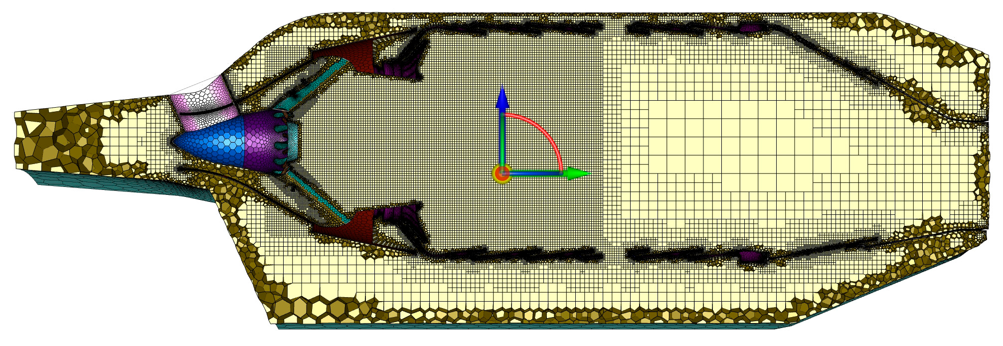
3.1. Combustor Geometry and Mesh Generation

The combustor geometry is shown in Figure 1. The combustor is a can-annular combustor consisting of 12 flame tubes. Due to its periodic characteristics, this study selected one of the 12 flame tubes and the adjacent cooling gas mixing air flow space as the research object. First, the NX 10.0 software was used to capture the 1/12 section of the can-annular combustor, and the fluid domain was extracted to construct the geometric model. The model was subsequently refined using ANSYS SpaceClaim 2021 (pre-processing software) to ensure the geometric model’s integrity and accuracy.
The combustor grid is shown in Figure 2. In terms of grid generation, a polyhedral-hexahedral core grid based on mosaic technology is employed in this study. The mosaic grid technology can generate hexahedral grids in the main combustion zone and polyhedral grids in the boundary layer and complex geometric structure areas, which reduces the number of grids, saves computational resources, and maintains simulation accuracy. Specifically, mesh refinement was performed in the swirler’s pre-mixing region, the leading and trailing edges of the swirler blade, the main combustion zone, and other complex flow regions. A boundary layer grid was also applied to the flame tube wall to ensure the accurate capture of flow field details.
To ensure mesh independence while maintaining approximate consistency in mesh quality indicators, this study generated five meshes with varying numbers of elements, which were 4.69 million, 5.51 million, 6.19 million, 7.03 million, and 8.55 million, respectively. Mesh generation was conducted using the ANSYS Meshing mode, and the sensitivity analysis was performed by incrementally increasing the number of meshes. These five types of meshes were imported into the Fluent Solution mode, and the same boundary conditions were applied and calculated until convergence. By extracting the axial temperature distribution [42] along the computational domain’s central axis, the influence of the mesh number on the computational results was analysed.
As shown in Figure 3, the axial temperature distribution error between 6.19 million and 7.03 million grids is less than 1%, indicating that the calculation results are minimally affected by the number of grids when it reaches 6.19 million, satisfying the grid independence requirements. Therefore, in this study, 6.19 million grids were used for subsequent numerical simulations.

3.2. Boundary Conditions

In the numerical simulation, all gaseous substances are considered as incompressible ideal gas. Taking the simulation results for methanol as an example, the high-temperature combustion gases are accelerated through the converging duct to the combustor outlet. The calculated outlet temperature corresponds to a local speed of sound of 685.6 m/s, resulting in an outlet Mach number of approximately 0.261. This value, being well below the threshold of 0.3, satisfies the prerequisite for the incompressible ideal gas assumption [41,43,44]. The boundary conditions were set as follows: the primary and pilot fuel inlets were assigned mass flow inlet conditions; the air inlet was also set as a mass flow inlet, and the gas outlet was assigned a pressure outlet condition. The annular combustor typically employs periodic boundary conditions [45,46,47]. Since the combustor is annular, complex combustion reactions occur only in the flame tube, so the flow of cooling and mixing gases outside the flame tube is less intense. Therefore, the boundaries on both sides of the fluid domain through which the cooling and mixing gases pass were assigned as symmetric boundary conditions to simulate the flow characteristics of the entire combustor. The key parameters are listed in Table 1 below.

3.3. Swirler Geometry

As shown in Figure 4, the studied combustor is a centrally staged dry low emission (DLE) combustor with a swirl nozzle design. The centre of the swirler is equipped with a pilot fuel lotus nozzle, and the periphery is designed with a strong swirling flow to rectify the incoming air and optimise air uniformity into the flame tube. The fuel nozzle is located on the swirl blade. This design offers two advantages: first, the pilot flame is placed in a small recirculation zone formed downstream of the lotus head, which significantly increases combustion stability; second, the primary fuel is ejected from the opening near the leading edge of the blade, achieving uniform fuel–air mixing while rectifying the air to form a premixed gas. This design not only ensures combustion process stability but also provides a solid foundation for low NOx emissions.

3.4. Cases Under Different PFRs

Based on existing research and combustor design principles, the fuel at the combustor’s top significantly influences combustion performance. By adjusting the PFR, NOx emission levels can be effectively controlled. Increasing the PFR increases the proportion of diffusion combustion in the overall combustion process, exacerbating incomplete combustion and negatively impacting combustor performance. Therefore, when designing the PFR, it is essential to consider the adverse effects of the diffusion flame on combustor performance while ensuring combustion stability. A proper coordination of these two factors can minimise combustor performance degradation while ensuring combustion stability. This design strategy not only helps to optimise combustor efficiency but also ensures low NOx emissions.
The PFR of the combustor is designed for methane. After switching to methanol fuel, the air requirement is significantly reduced due to methanol’s oxygen-containing nature and the low combustion temperature. Additionally, methanol combustion is more complete, and the negative impact of diffusion combustion on the overall combustion performance is relatively minor [48]. Therefore, theoretically, the degradation of combustor performance caused by the pilot diffusion flame is also reduced. Based on these characteristics, this study investigated the combustor under different PFRs using methanol and simulated the combustor under the following conditions, which are listed in Table 2.
For comparison, this study also investigated the combustor under different PFRs using methane and simulated the combustor under the following conditions, which are listed in Table 3.
This study includes two sets of simulations, each with eight cases, for a total of sixteen cases. Through the above conditions, the influence of the PFR on the performance and emission characteristics of the methanol combustor was analysed, and the relationship was summarised.

3.5. Validation of the Numerical Methods

The purpose of this study is to investigate the performance of various PFRs when methanol is used as fuel in the combustor and compare it with methane. The research focuses on the combustor’s overall performance rather than flow field details or intermediate products. Therefore, the Eddy Dissipation Model (EDM), which is widely used in engineering, was selected as the combustion model, and a simple one-step reaction was employed for the numerical simulation of chemical reactions. The simplified chemical reaction mechanism significantly enhances computational efficiency and is suitable for engineering design and optimisation. The simplified reaction has limited ability to capture intermediate products, but this study does not focus on intermediate products. The oxygen-containing nature of methanol molecules reduces oxygen dependency during combustion and results in a low adiabatic combustion temperature. This study focuses on the effects of these two characteristics on outlet parameters, including temperature, velocity, and NOx emissions. The same method was employed to simulate the combustor of a 20 MW gas turbine during the design stage. The simulation results using methane as the fuel agreed well with subsequent test data, providing strong support for the gas turbine’s successful testing. Additionally, the numerical simulation results for methane combustion were compared with data from the literature [12,13]. The results indicate that the NOx emission trends are consistent, further validating the method’s rationality.
Although a detailed chemical reaction mechanism was not used in this study, the simplified method is sufficient to support the research conclusions. The research focuses on the effect of PFR on combustion performance, where methanol’s oxygen-containing nature plays a crucial role, rather than the detailed chemical reaction process. Future research can further optimise simulation accuracy by introducing detailed mechanisms, but the simplified method used in this study meets the requirements for engineering design and optimisation.
While the numerical method employed in this study was validated for predicting global properties at the outlet and periphery of the equipment, it is important to acknowledge its limitations in capturing detailed local properties. The simplified numerical method, though effective for engineering design and optimisation purposes, has inherent constraints in predicting precise local properties. The temperature distribution and NOx concentration contours presented in this study should be interpreted as qualitative indicators of high-temperature zones’ influence on NOx formation rather than quantitative predictions.

4. Results and Discussion

In this section, numerical simulations are employed to study the combustor’s performance under different PFRs, focusing on the following aspects: outlet velocity distribution, outlet temperature distribution, combustor efficiency, outlet temperature distribution coefficient (OTDF), and NOx emissions.
By comparing the combustor performance of methanol and methane, this study aims to reveal the performance differences between the two fuels and evaluate the influence of the PFR on combustor performance. The research results will provide a theoretical foundation and engineering guidance for low-NOx combustor design.
It should be noted that the contours presented in this section are primarily intended to illustrate general trends and qualitative patterns rather than to provide precise local properties. These visualisations are intended to improve our understanding of the underlying relationship between the oxygenated nature of methanol and its effect on combustor performance.

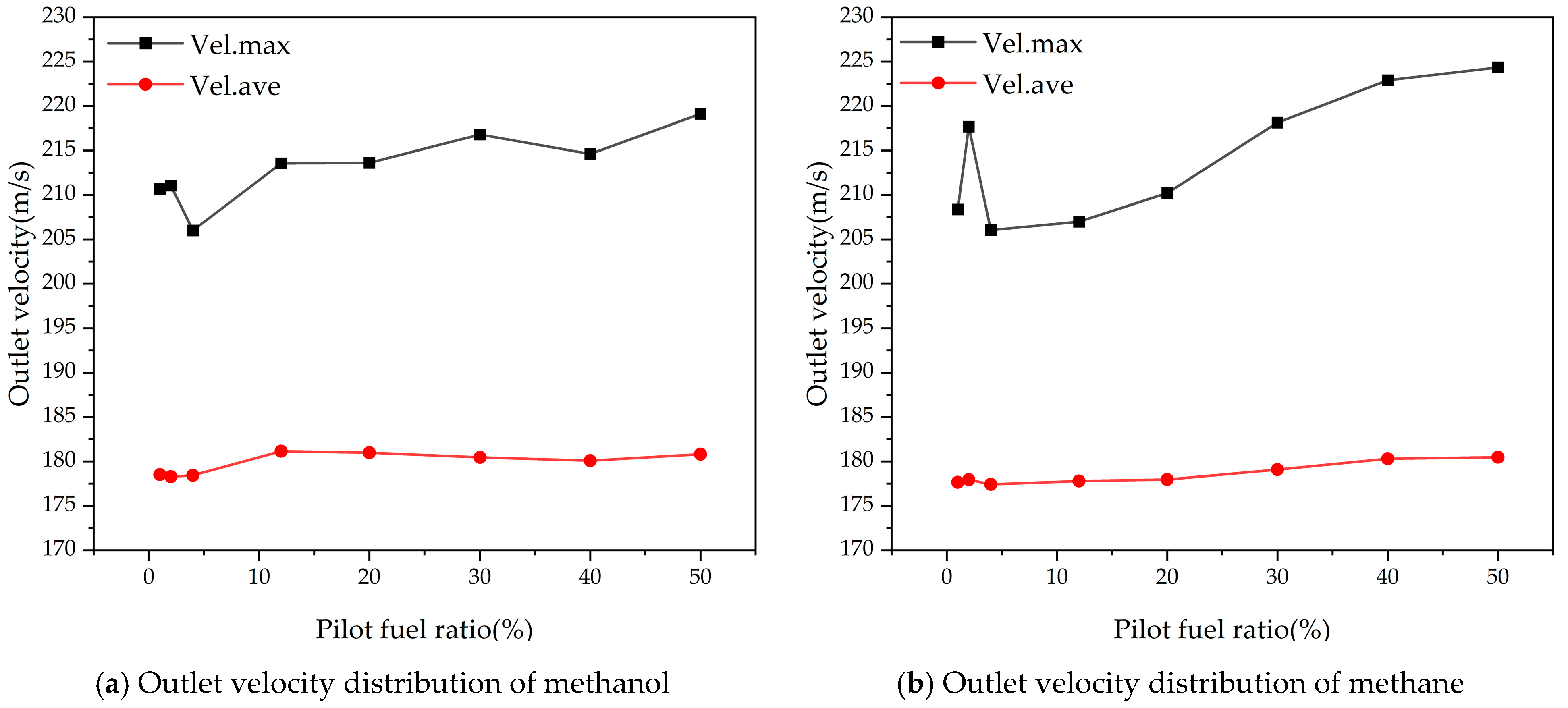
4.1. Outlet Velocity Distributuion

The simulation results of the outlet velocity distribution are shown in Figure 5. As the PFR increases, the average outlet velocity of the combustor fluctuates slightly, and the maximum outlet velocity also fluctuates to some extent. Specifically, when the PFR increases from 1% to 50%, the maximum outlet velocity fluctuates between 206 m/s and 219.12 m/s for methanol combustion, while the average velocity remains relatively stable between 178.29 m/s and 181.16 m/s. When methane is used as the fuel, the maximum outlet velocity fluctuates between 206.02 and 224.34 m/s, and the average velocity is basically stable between 177.42 and 180.48 m/s. Due to methane’s higher calorific value, the fuel inlet flow rate is lower, resulting in a slightly lower total gas volume at the outlet compared to methanol, and thus a slightly lower average velocity than that of methanol combustion. The enhancement of the pilot diffusion flame theoretically leads to increased combustion inhomogeneity, yet the maximum velocity at the outlet shows only a slight upward trend in Figure 5. This indicates that the combustor’s mixing design has sufficient redundancy to reduce the impact of combustion inhomogeneity on the downstream outlet.

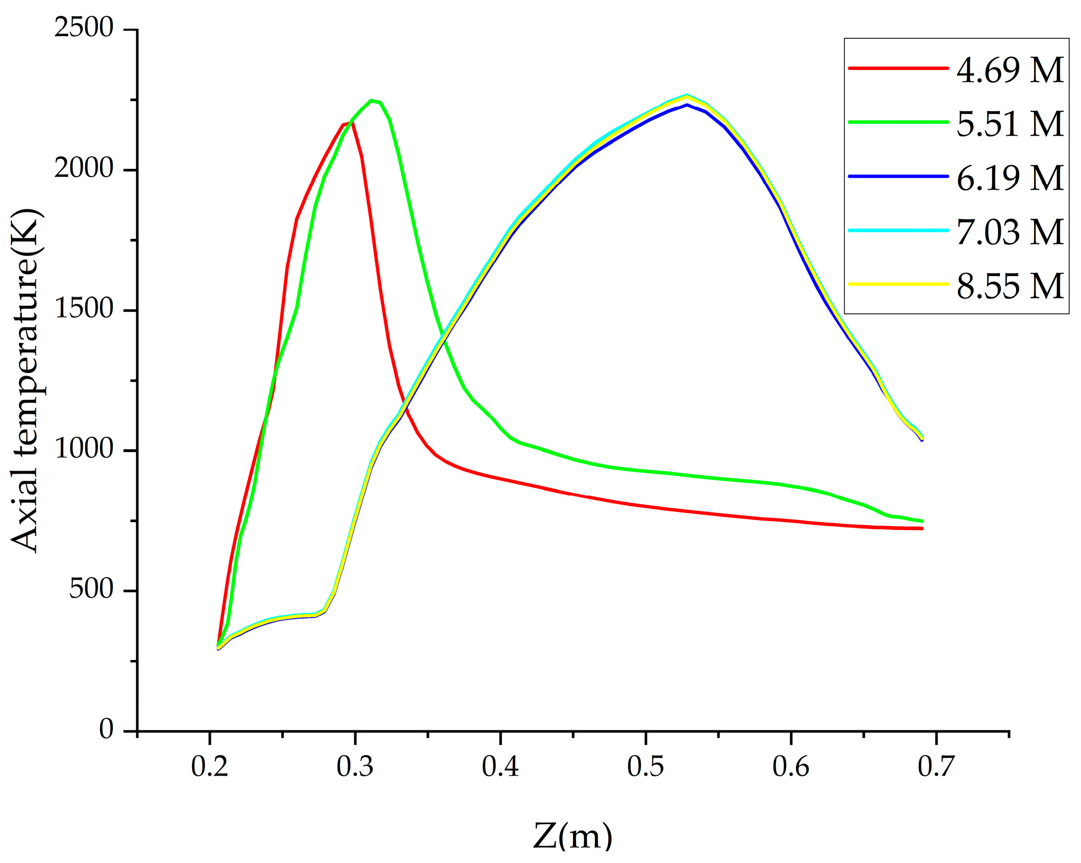
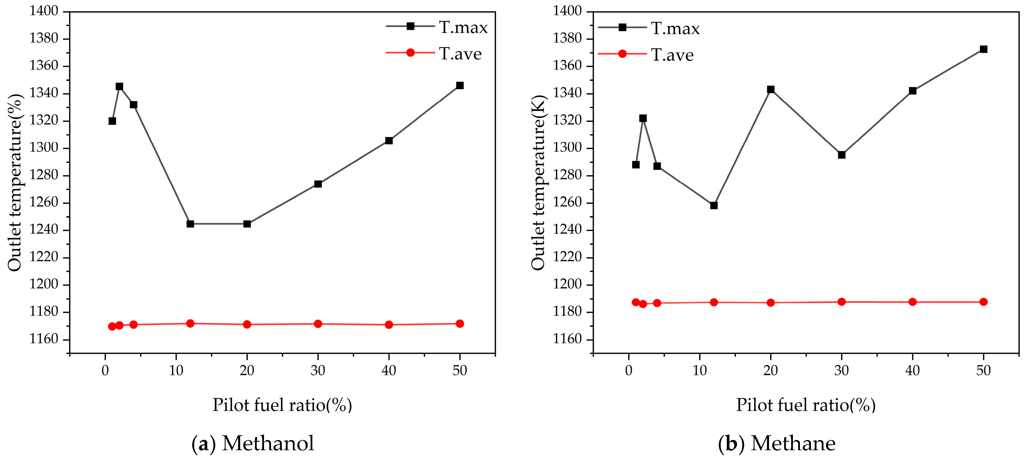
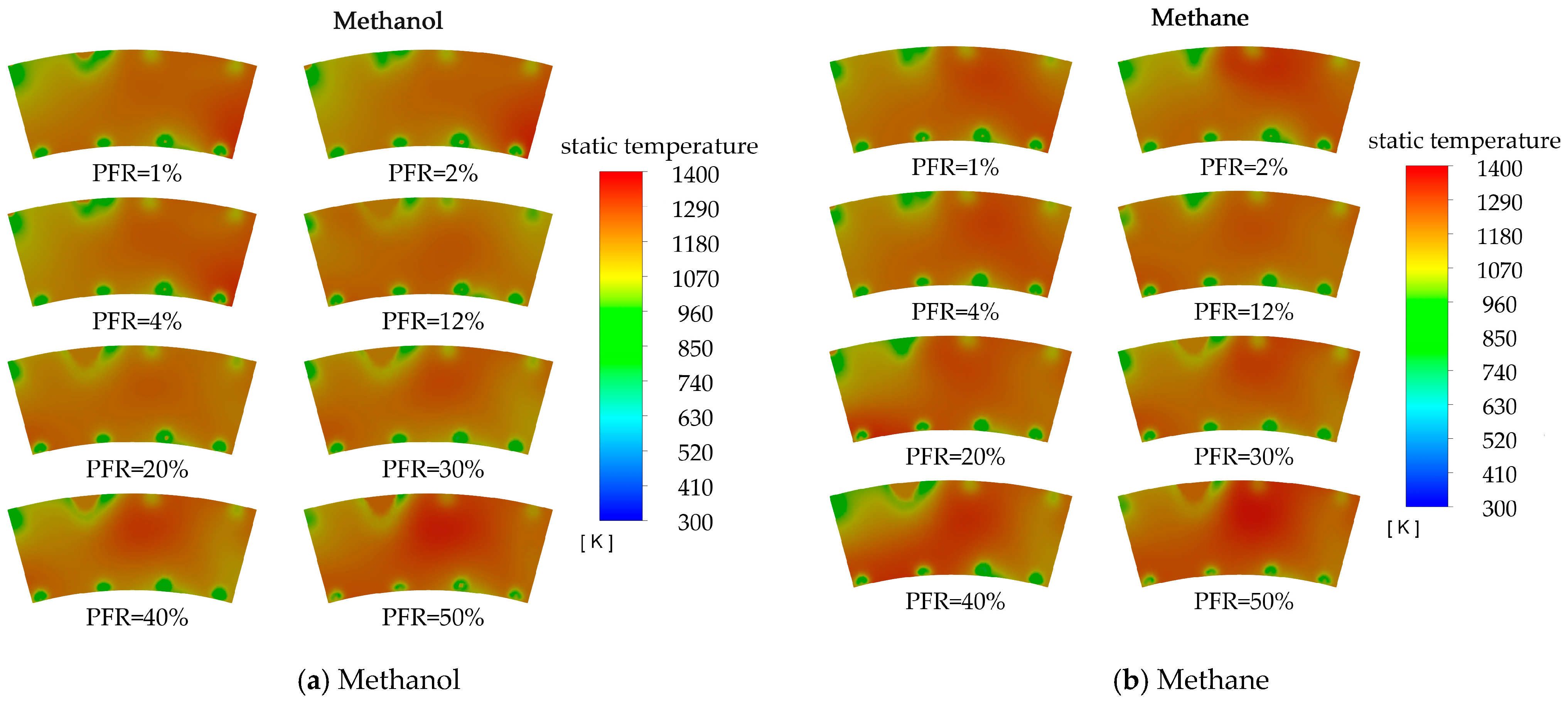
4.2. Oulet Temperature Distribution

As illustrated in Figure 6, with increasing PFR, the average temperature at the combustor outlet remains almost unchanged for both fuels. Specifically, the average outlet temperature for methanol combustion is stable between 1169.72 K and 1171.96 K, while for methane combustion, it is slightly higher, ranging from 1186.14 K to 1187.77 K. However, the maximum outlet temperature shows an upward trend. For methanol, the maximum temperature ranges from 1244.76 K to 1346.19 K, and for methane, it ranges from 1258.33 K to 1372.67 K. This phenomenon can be attributed to the concentrated combustion of the pilot diffusion flame, which leads to the formation of local high-temperature zones, thereby worsening the outlet temperature distribution.
Owing to methane’s higher calorific value and lower fuel inlet flow rate, the total gas flow rate is smaller than that of methanol for the same heat release, resulting in a slightly higher average outlet temperature. The upward trend in the maximum outlet temperature is primarily attributable to the formation of a local high-temperature zone due to the concentrated combustion of the pilot diffusion flame.
The temperature contours in Figure 7 intuitively illustrate the differences in outlet temperature between methanol and methane combustion. On the one hand, the average outlet temperature for methanol combustion is 16 K to 18 K lower than that for methane, confirming the inhibitory effect of methanol’s lower calorific value on flame temperature. On the other hand, both fuels exhibit local high-temperature zones under different PFRs, but no concentrated hot spots or hot streaks are present, which demonstrates that the existing cooling design is effective for both fuels.

4.3. Outlet Temperature Distribution Factor

As shown in Figure 8, the OTDF of the combustor fluctuates with the increase in PFR under different fuel conditions, but it remains within a reasonable range (0.25–0.35) in many cases [49]. In other cases, the OTDF is significantly lower than 0.25, indicating a more uniform temperature distribution. This suggests that the combustor’s cooling and mixing design has sufficient redundancy to maintain a high-quality outlet temperature distribution even after fuel change.
It can also be seen from Figure 6 and Figure 7 in Section 4.2 that the outlet temperature distribution of the combustor does not change significantly with PFR. Despite the increase in PFR and the corresponding increase in the proportion of diffusion combustion, the high-temperature zone is not overly concentrated, and hot spots or hot streaks do not appear. The temperature contours and the calculated OTDF values demonstrate that the outlet temperature of the combustor maintains good uniformity when using both fuels.

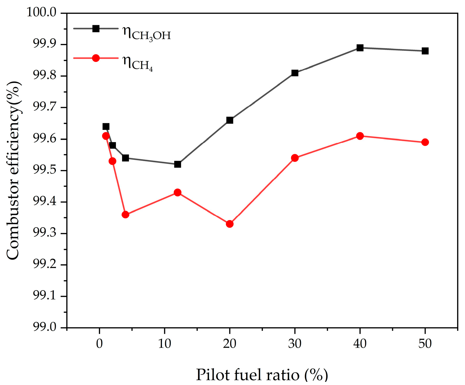
4.4. Combustor Efficiency
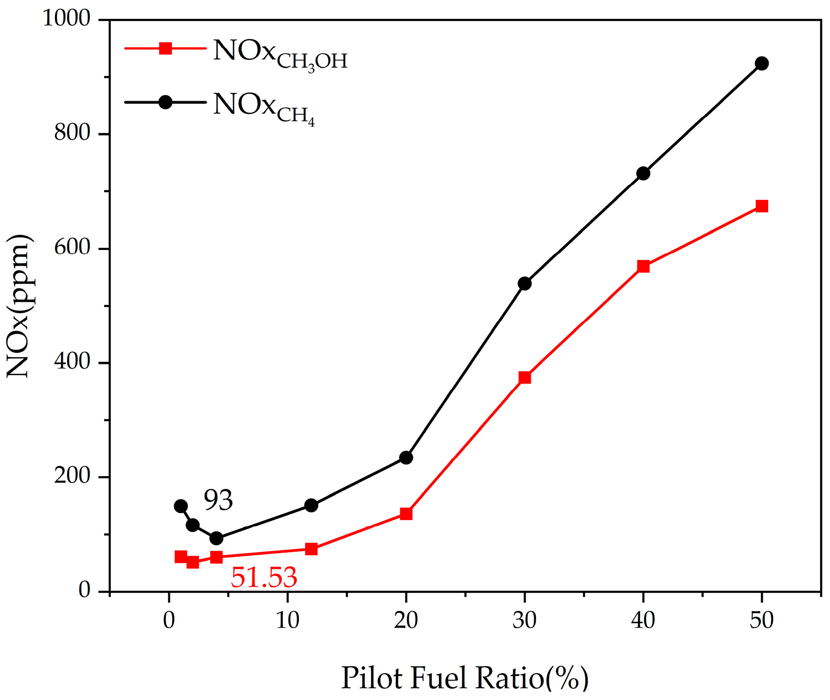
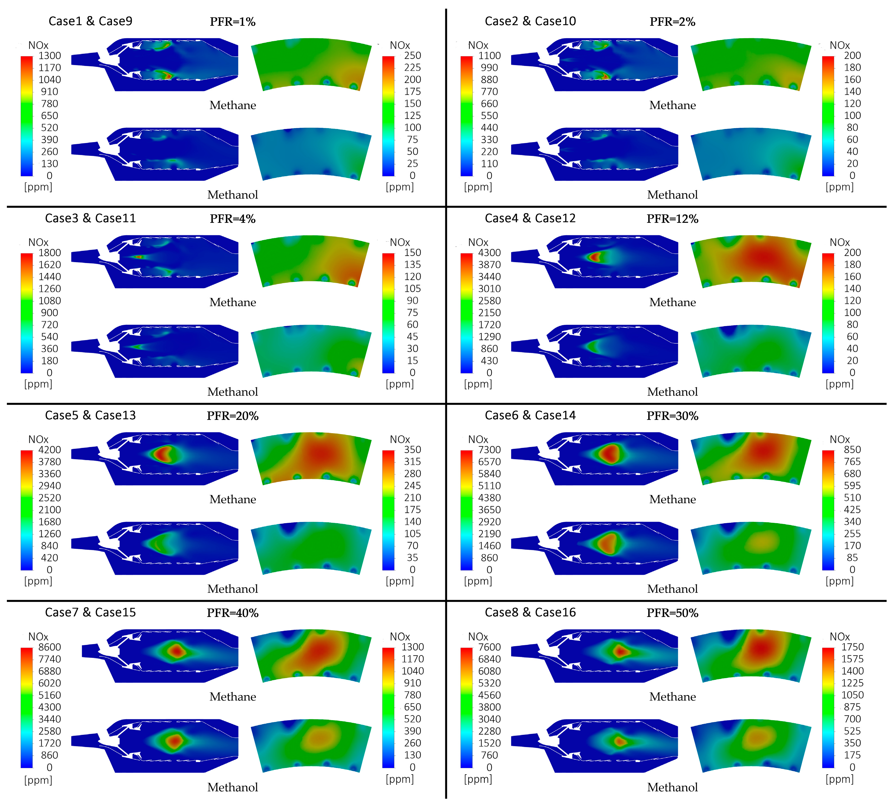
As shown in Figure 9, the combustor’s efficiency with methanol remained above 99.5% in all cases, while the combustor’s efficiency with methane remained above 99.3% with a small fluctuation. Although the proportion of diffusion combustion in the total combustion process increases with increasing PFR, it does not have a significant negative effect on the combustor’s efficiency.
As the most common gaseous fuel, methane exhibits high combustor efficiency. Under the design of this type of combustor, changes in fuel and air distribution in the head have minimal impact on the combustor’s efficiency, which remains only slightly lower than that of methanol.
As an oxygen-containing fuel, methanol has a low oxygen demand during combustion, which further mitigates the issue of incomplete combustion caused by diffusion combustion. The diffusion combustion of the pilot fuel has little effect on combustor efficiency. Therefore, in all cases, methanol combustion in the combustor demonstrates high efficiency, surpassing that of methane.

4.5. NOx Emission

As shown in Figure 10, the NOx emission decreases and then increases with increasing PFR, reaching a minimum value. Specifically, when the PFR increases from 1% to 2%, the NOx emission decreases from 61.02 ppm to 51.53 ppm; when the PFR is further increased to 50%, the NOx emission rises significantly to 674.21 ppm. It is worth noting that the low NOx range for methanol combustion is relatively wide, with NOx emissions remaining at a low level (51.53 ppm–74.47 ppm) over a PFR range of 1% to 12%.
When methane is used as the fuel, the trend of NOx emissions is similar to that of methanol combustion. As the PFR increases, the NOx emission first decreases and then increases, reaching a minimum value. However, the NOx emission value for methane combustion is significantly higher than that for methanol combustion. The low NOx range for methane combustion is narrow, with relatively low NOx emissions (93 ppm–116.35 ppm) only near a PFR of 2% to 4%. This level is still significantly higher than the low NOx emission level of methanol combustion.
As shown in Figure 11, the NOx concentration contours reveal the spatial regulation mechanism of PFR on pollutant formation. As the PFR increases from 1% to 50%, the NOx enrichment zone gradually shifts from the main combustion zone to the pilot flame core, becoming highly concentrated in the pilot recirculation zone when the PFR is greater than or equal to 12%. This phenomenon is directly related to the formation of a local high-temperature zone in diffusion combustion. When the temperature exceeds 1900 K, the rate of formation of thermal NOx, which is dominated by the Zeldovich mechanism, increases exponentially [50].
The fuel type significantly influences the spatial distribution characteristics of the NOx concentration. The internal cross-sectional contours of the combustor show that the area and value of the NOx high-concentration zone for methane combustion are significantly higher than those for methanol combustion. The outlet cross-sectional contours further confirm this difference, indicating that methanol’s lower calorific value effectively reduces the formation intensity of thermal NOx by inhibiting the formation of local high-temperature zones.
It is evident that methanol significantly outperforms methane in terms of NOx emissions in the combustor of this type of gas turbine.
The local properties shown in Figure 11 indicate possible measurement points for further experiments; they are not precise predictions. The contours in this study are intended solely for qualitative analysis, demonstrating the general trends of combustion temperature distribution and its influence on thermal NOx formation. These visualisations are particularly useful for illustrating how methanol’s low calorific value affects the combustion temperature and subsequently inhibits thermal NOx generation. It is important to emphasise that these contours should not be interpreted as precise quantitative predictions of the local temperature or NOx concentration distributions.

5. Conclusions

In this study, the combustion performance of methanol and methane in a gas turbine combustor was systematically compared via numerical simulations, and the influence mechanism of the pilot fuel ratio (PFR) on the nitrogen oxide (NOx) emission was discussed. The results show that methanol, as an oxygenated fuel, has significant advantages in combustor efficiency and NOx emission control, especially in the low PFR range. The main conclusions are as follows:
  • The outlet parameters of the methanol combustor are comparable to those of the methane combustor, yet the combustor’s efficiency is superior. The difference between the average outlet velocity of methanol and methane is less than 1%; the difference in temperature between the two fuels is less than 1%; and the OTDF is similar to that of methane. The combustor efficiency of methanol (99.52–99.89%) is 0.2–0.3% higher than that of methane (99.33–99.61%). The oxygenated nature of methanol is the key mechanism for improving efficiency by inhibiting incomplete diffusion combustion.
  • NOx emission control of methanol achieves significant advantages in two main aspects. Under all operating conditions, NOx emissions from methanol combustion are only 40–78% of those from methane combustion, with the lowest emission value (51.53 ppm) occurring at a PFR of 2%. In contrast, methane combustion reaches its lowest NOx emission value (93 ppm) at a PFR of 4%. The emission advantages are as follows: (1) Temperature control: the low adiabatic flame temperature of methanol suppresses thermal NOx formation, which is dominated by the Zeldovich mechanism. (2) Optimisation of air utilisation: The oxygenated nature of methanol reduces the oxygen demand in the main combustion zone. Excess air improves cooling in the high-temperature area, thereby widening the low-emission window (methanol: PFR = 1–12%; methane: PFR = 2–4%).
This study shows that the combustor designed for methane can be adapted to methanol combustion without structural modification, and the performance of the methanol combustor surpasses that of the methane combustor. The results of this study are preliminary and require further experiments for validation. Future research will verify the reliability of the local properties with experimental data in order to provide more solid theoretical support for the technical application of the methanol fuel in gas turbines.

Author Contributions

Conceptualization, J.C. and H.W.; methodology, J.C.; software, J.C.; validation, J.C., H.W. and R.Y.; formal analysis, J.C.; investigation, J.C.; resources, H.W.; data curation, J.C.; writing—original draft preparation, J.C.; writing—review and editing, R.Y. and H.W.; visualisation, Y.W.; supervision, J.T.; project administration, R.Y.; funding acquisition, H.W. All authors have read and agreed to the published version of the manuscript.

Funding

This research received no external funding.

Data Availability Statement

The raw data supporting the conclusions of this article will be made available by the authors on request.

Conflicts of Interest

The authors declare no conflicts of interest.

Abbreviations

The following abbreviations are used in this manuscript:
CFDMultidisciplinary Digital Publishing Institute
PFRPilot fuel ratio
OTDFOutlet temperature distribution factor

References

  1. Zhang, B.; Chen, Y.; Wang, Z.; Shakibi, H. Thermodynamic, environmental, and optimization of a new power generation system driven by a gas turbine cycle. Energy Rep. 2020, 6, 2531–2548. [Google Scholar]
  2. Wu, D.W.; Wang, R.Z. Combined cooling, heating and power: A review. Prog. Energy Combust. Sci. 2006, 32, 459–495. [Google Scholar]
  3. Liu, Y.; Sun, X.; Sethi, V.; Nalianda, D.; Li, Y.G.; Wang, L. Review of modern low emissions combustion technologies for aero gas turbine engines. Prog. Aerosp. Sci. 2017, 94, 12–45. [Google Scholar]
  4. Budiyanto, M.A.; Nawara, R. The optimization of exergoenvironmental factors in the combined gas turbine cycle and carbon dioxide cascade to generate power in LNG tanker ship. Energy Convers. Manag. 2020, 205, 112468. [Google Scholar]
  5. Faqih, M.; Omar, M.B.; Ibrahim, R.; Omar, B.A. Dry-Low Emission Gas Turbine Technology: Recent Trends and Challenges. Appl. Sci. 2022, 12, 10922. [Google Scholar] [CrossRef]
  6. Liu, M.; Shi, Y.; Fang, F. Combined cooling, heating and power systems: A survey. Renew. Sustain. Energy Rev. 2014, 35, 1–22. [Google Scholar]
  7. Pilavachi, P.A. Power generation with gas turbine systems and combined heat and power. Appl. Therm. Eng. 2000, 20, 1421–1429. [Google Scholar]
  8. Dennis, R.; Long, H.A.; Jesionowski, G. A literature review of NOx emissions in current and future state-of-the-art gas turbines. J. Eng. Gas Turbines Power 2024, 146, 030801. [Google Scholar]
  9. Correa, S.M. A review of NOx formation under gas-turbine combustion conditions. Combust. Sci. Technol. 1993, 87, 329–362. [Google Scholar]
  10. Okafor, E.C.; Somarathne, K.K.; Ratthanan, R.; Hayakawa, A.; Kudo, T.; Kurata, O.; Iki, N.; Tsujimura, T.; Furutani, H.; Kobayashi, H. Control of NOx and other emissions in micro gas turbine combustors fuelled with mixtures of methane and ammonia. Combust. Flame 2020, 211, 406–416. [Google Scholar]
  11. Ma, Y.; Liu, J.; Zhu, L.; Li, Q.; Guo, Y.; Liu, H.; Yu, D. Multi-objective performance optimization and control for gas turbine Part-load operation Energy-saving and NOx emission reduction. Appl. Energy 2022, 320, 119296. [Google Scholar]
  12. Chen, A.G.; Maloney, D.J.; Day, W.H. Humid Air NOx Reduction Effect on Liquid Fuel Combustion. In Proceedings of the ASME Turbo Expo, Amsterdam, The Netherlands, 3–6 June 2002. [Google Scholar]
  13. Holdeman, J.D.; Chang, C.T. Low Emissions RQL Flametube Combustor Component Test Results; NASA/TM-2001-210678; NASA: Cleveland, OH, USA, 2001. [Google Scholar]
  14. Beck, C.H.; Koch, R.; Bauer, H.J. Investigation of the Effect of Incomplete Droplet Prevaporization on NOx Emissions in LDI Combustion Systems. J. Eng. Gas Turbines Power 2008, 130, 218–230. [Google Scholar]
  15. Spadaccini, C.M.; Peck, J.; Waitz, I.A. Catalytic Combustion Systems for Micro-Scale Gas Turbine Engines. J. Eng. Gas Turbines Power 2007, 129, 49–60. [Google Scholar]
  16. Wang, W.; Xiao, J.F.; Gao, S.; Wang, F.; Li, X.F.; Hu, M.Q. Numerical Study on Influences of Air-Fuel Ratio on Combustion Instability in Gas Turbine Combustor. J. Combust. Sci. Technol. 2019, 25, 439–444. [Google Scholar]
  17. Shen, W.; Liu, L.; Hu, Q.; Liu, G.; Wang, J.; Zhang, N.; Wu, S.; Qiu, P.; Song, S. Combustion Characteristics of Ignition Processes for Lean Premixed Swirling Combustor under Visual Conditions. Energy 2021, 218, 119521. [Google Scholar]
  18. Zhang, Y.; Wang, J.; Liu, Y.; Yan, Y. Numerical simulation of the influence of fuel allocation method on regional NOx production in a single sector combustor. Energy 2023, 270, 126923. [Google Scholar]
  19. Zong, C.; Lyu, Y.; Guo, D.; Li, C.; Zhu, T. Experimental and numerical study on emission characteristics of the double annular swirler under different pilot fuel ratios. In Proceedings of the ASME Turbo Expo: Power for Land, Sea, and Air, Oslo, Norway, 11–15 June 2018. [Google Scholar]
  20. Zong, C.; Ji, C.; Cheng, J.; Zhu, T. Effects of Pilot Fuel Ratio on Combustion Process: Flow Field Structure and Pollutant Emissions. J. Therm. Sci. 2023, 32, 2321–2335. [Google Scholar]
  21. Glaude, P.A.; Sirjean, B.; Fournet, R.; Bounaceur, R.; Vierling, M.; Montagne, P.; Molière, M. Combustion and oxidation kinetics of alternative gas turbines fuels. In Proceedings of the ASME Turbo Expo: Power for Land, Sea, and Air, Düsseldorf, Germany, 16–20 June 2014. [Google Scholar]
  22. Levy, Y.; Erenburg, V.; Roizman, A.; Sherbaum, V. Numerical and Experimental Study of the Emissions During Methanol Combustion. In Proceedings of the ASME Turbo Expo: Power for Land, Sea, and Air, Oslo, Norway, 11–15 June 2018. [Google Scholar]
  23. Von KleinSmid, W.H.; Schreiber, H.; Klapatch, R.D. Methanol combustion in a 26-MW gas turbine. In Proceedings of the ASME 1981 International Gas Turbine Conference and Products Show, Houston, TX, USA, 9–12 March 1981. [Google Scholar]
  24. Smith, K.O. Ultra-Low NOx Combustor Concept for Methanol Firing. In Proceedings of the ASME Turbo Expo: Power for Land, Sea, and Air, Phoenix, AZ, USA, 27–31 March 1983. [Google Scholar]
  25. Chudnovsky, B.; Reshef, M.; Talanker, A. Evaluation of methanol and light fuel oil blends firing at a 50 MW gas turbine. In Proceedings of the ASME Power Conference 2017, Charlotte, CA, USA, 26–30 June 2017. [Google Scholar]
  26. Hain, Y.; Chudnovsky, B.; Talanker, A.; Kunin, A.; Rappoport, N.; Reshef, M.; Shternshus, M.; Baitel, S. Methanol fuel as low cost alternative for emission reduction in gas turbines and utility boilers. In Proceedings of the 20th International Conference on Nuclear Engineering, Anaheim, CA, USA, 30 July–3 August 2012. [Google Scholar]
  27. Chudnovsky, B.; Reshef, M.; Keren, M.; Baitel, S. Successful Implementation of Methanol Firing at 50 MW Gas Turbine for Long Term Operation. In Proceedings of the ASME Power Conference 2015, San Diego, CA, USA, 28 June–2 July 2015. [Google Scholar]
  28. Tsang, W. Chemical Kinetic Data Base for Combustion Chemistry. Part 2. Methanol. J. Phys. Chem. Ref. Data 1987, 16, 471–508. [Google Scholar] [CrossRef]
  29. Egolfopoulos, F.N.; Du, D.X.; Law, C.K. A Comprehensive Study of Methanol Kinetics in Freely-Propagating and Burner-Stabilized Flames, Flow and Static Reactors, and Shock Tubes. Combust. Sci. Technol. 1992, 83, 33–75. [Google Scholar]
  30. Yarasai, S.S.; Ravi, D.; Yoganand, S.; Rajagopal, T.K. Numerical investigation on the performance and combustion characteristics of a cavity based scramjet combustor with novel strut injectors. Int. J. Hydrogen Energy 2023, 48, 5681–5695. [Google Scholar]
  31. Ji, C.; Shi, W.; Ke, E.; Cheng, J.; Zhu, T.; Zong, C.; Li, X. Numerical Investigations on the Effects of Dome Cooling Air Flow on Combustion Characteristics and Emission Behavior in a Can-Type Gas Turbine Combustor. Aerospace 2024, 11, 338. [Google Scholar] [CrossRef]
  32. Feng, Y.; Li, X.; Ren, X.; Gu, C.; Lv, X.; Li, S.; Wang, Z. Influence of the turbulence model on the numerical predictions of cold turbulent flow in a heavy-duty gas turbine DLN combustor. Int. J. Therm. Sci. 2024, 196, 108735. [Google Scholar]
  33. Shih, T.H.; Liou, W.W.; Shabbir, A.; Yang, Z.; Zhu, J. A new k-ϵ eddy viscosity model for high Reynolds number turbulent flows. Comput. Fluids 1995, 24, 227–238. [Google Scholar]
  34. ANSYS, Inc. ANSYS Fluent Theory Guide; ANSYS, Inc.: Canonsburg, PA, USA, 2020; pp. 54–55. [Google Scholar]
  35. Chatterjee, D.; Datta, A.; Ghosh, A.K.; Som, S.K. Effects of inlet air swirl and spray cone angle on combustion and emission performance of a liquid fuel spray in a gas turbine combustor. J. Inst. Eng. 2004, 85, 41–46. [Google Scholar]
  36. Cho, H.C.; Lee, Y.K. Reactor performance with primary/secondary swirl intensity and direction in coal gasification process. Int. J. Energy Res. 2001, 25, 1151–1163. [Google Scholar]
  37. Majidi, K. CFD modeling of non-premixed combustion in a gas turbine combustor. In Proceedings of the Fluids Engineering Division Summer Meeting, Montreal, QC, Canada, 14–18 July 2002. [Google Scholar]
  38. Zettervall, N.; Fureby, C.; Nilsson, E.J.K. Evaluation of Chemical Kinetic Mechanisms for Methane Combustion: A Review from a CFD Perspective. Fuels 2021, 2, 210–240. [Google Scholar] [CrossRef]
  39. Xing, C.; Chen, X.; Qiu, P.; Liu, L.; Yu, X.; Zhao, Y.; Zhang, L.; Liu, J.; Hu, Q. Effect of fuel flexibility on combustion performance of a micro-mixing gas turbine combustor at different fuel temperatures. J. Energy Inst. 2022, 102, 100–117. [Google Scholar]
  40. Tang, C.; Yao, Q.; Jin, W.; Li, J.; Yan, Y.; Yuan, L. Effect of swirler geometry on the outlet temperature profile performance of a model gas turbine combustor. Appl. Therm. Eng. 2025, 260, 124946. [Google Scholar]
  41. Wang, K.; Li, F.; Zhou, T.; Wang, D. Numerical simulations on the effect of swirler installation angle on outlet temperature distribution in gas turbine combustors. Appl. Therm. Eng. 2024, 240, 122252. [Google Scholar]
  42. Wang, D.; Li, F.; Lin, H.; Zhou, T.; Zhao, K. Research on substitutability of single-dome versus triple-dome center staged combustor. Case Stud. Therm. Eng. 2024, 60, 104633. [Google Scholar]
  43. Sun, J.; Yang, Q.; Zhao, N. Numerically study of CH4/NH3 combustion characteristics in an industrial gas turbine combustor based on a reduced mechanism. Fuel 2022, 327, 124897. [Google Scholar] [CrossRef]
  44. Wang, Q.; Fan, W.; Yi, J. Effect of rear blunt body structure and inlet conditions on the flow and combustion characteristics of an advanced vortex combustor for a gas turbine. Appl. Therm. Eng. 2025, 259, 124963. [Google Scholar] [CrossRef]
  45. Hu, G.; Qin, Q.; Jin, W.; Li, J. Large eddy simulation of the influences of the pilot-stage structure on the flow characteristics in a centrally staged high-temperature-rise combustor. Aerospace 2022, 9, 782. [Google Scholar] [CrossRef]
  46. Liu, W.; Yang, Q.; Xue, R.; Wang, H. Large eddy simulation study of flow dynamics in a multiswirler model combustor at elevated pressure and high temperature. J. Therm. Sci. Eng. Appl. 2019, 11, 061019. [Google Scholar] [CrossRef]
  47. Mongia, H. Recent progress in comprehensive modeling of gas turbine combustion. In Proceedings of the 46th AIAA Aerospace Sciences Meeting and Exhibit, Reno, NV, USA, 7–10 January 2008; American Institute of Aeronautics and Astronautics: Reston, VA, USA, 2008; p. 1445. [Google Scholar]
  48. Chudnovsky, B.; Livshits, D.; Baitel, S. Burning methanol and its blends attractive alternative for emission reduction. In Proceedings of the ASME Power Conference 2016, Charlotte, NC, USA, 26–30 June 2016. [Google Scholar]
  49. Huang, Y.; Lin, Y.Z. Combustion and Combustor; Beihang University Press: Beijing, China, 2009; Volume 9, pp. 300–301. [Google Scholar]
  50. Wulff, A.; Hourmouziadis, J. Technology review of aeroengine pollutant emissions. Aerosp. Sci. Technol. 1997, 1, 557–572. [Google Scholar] [CrossRef]
Figure 1. Gas turbine combustor geometry.
Energies 18 01765 g001
Figure 2. Computational grid of the gas turbine combustor.
Energies 18 01765 g002
Figure 3. Validation of grid independence based on the axial temperature distribution along the central axis of the combustor.
Energies 18 01765 g003
Figure 4. Geometry of the swirler in the gas turbine combustor.
Energies 18 01765 g004
Figure 5. Outlet velocity distribution of the combustor for methanol and methane under different pilot fuel ratios (PFRs).
Energies 18 01765 g005
Figure 6. Outlet temperature distribution of the combustor for methanol and methane under different pilot fuel ratios (PFRs).
Energies 18 01765 g006
Figure 7. Temperature contours at the combustor outlet from CFD simulations (methanol and methane, PFR = 1–50%).
Energies 18 01765 g007
Figure 8. Outlet temperature distribution factor (OTDF) for methanol and methane under different pilot fuel ratios (PFRs).
Energies 18 01765 g008
Figure 9. Combustor efficiency for methanol and methane under different pilot fuel ratios (PFRs).
Energies 18 01765 g009
Figure 10. NOx emissions for methanol and methane under different pilot fuel ratios (PFRs).
Energies 18 01765 g010
Figure 11. NOx concentration contours in the combustor from CFD simulations (methanol and methane, PFR = 1–50%).
Energies 18 01765 g011
Table 1. Boundary conditions of methanol and methane combustion in the gas turbine combustor.
MethaneMethanol
Total fuel flow rate (kg/s)0.1060.2156
Inlet mass flow rate (kg/s)7.97.9
Inlet total pressure (MPa)1.2341.234
Inlet total temperature (K)636636
Outlet total pressure (MPa)1.1921.192
Table 2. Simulation cases for methanol combustion under different pilot fuel ratios (PFRs).
Pilot Fuel Mass Flow Rate (kg/s)Pilot Fuel Ratio (%)
Case10.0021
Case20.0052
Case30.0104
Case40.03012
Case50.05020
Case60.07630
Case70.10040
Case80.12650
Table 3. Simulation cases for methane combustion under different pilot fuel ratios (PFRs).
Pilot Fuel Mass Flow Rate (kg/s)Pilot Fuel Ratio (%)
Case90.0011
Case100.0022
Case110.0044
Case120.01212
Case130.02120
Case140.03230
Case150.04240
Case160.05350
Disclaimer/Publisher’s Note: The statements, opinions and data contained in all publications are solely those of the individual author(s) and contributor(s) and not of MDPI and/or the editor(s). MDPI and/or the editor(s) disclaim responsibility for any injury to people or property resulting from any ideas, methods, instructions or products referred to in the content.

