
A Single-Phase AC-AC Power Electronic Transformer Without Bulky Energy Storage Elements


Abstract
1. Introduction
2. Topology and Operating Principles of the Proposed PET
2.1. Proposed Topology
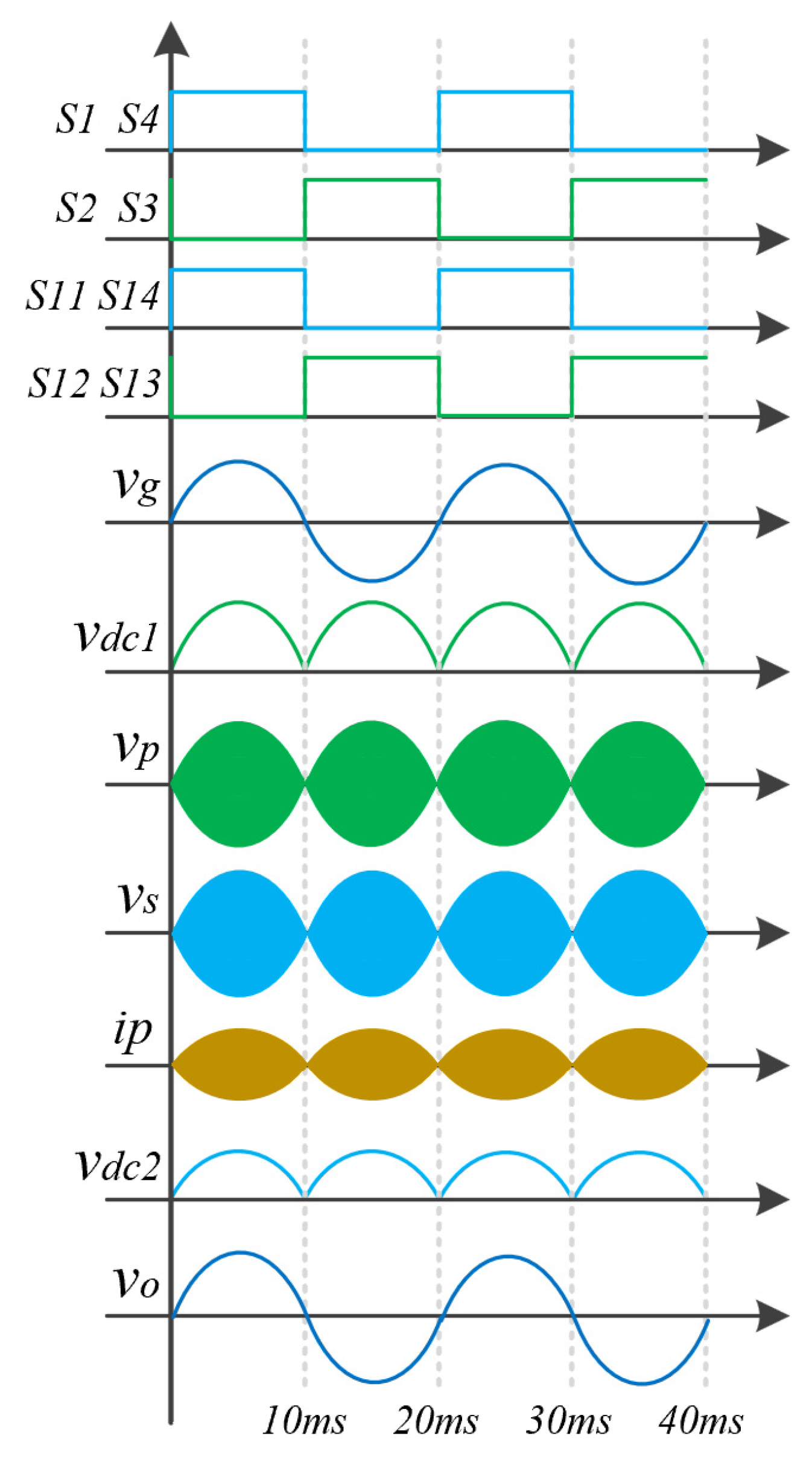
2.2. Operating Principles
3. ZVS Analysis and Control Scheme of the Proposed PET
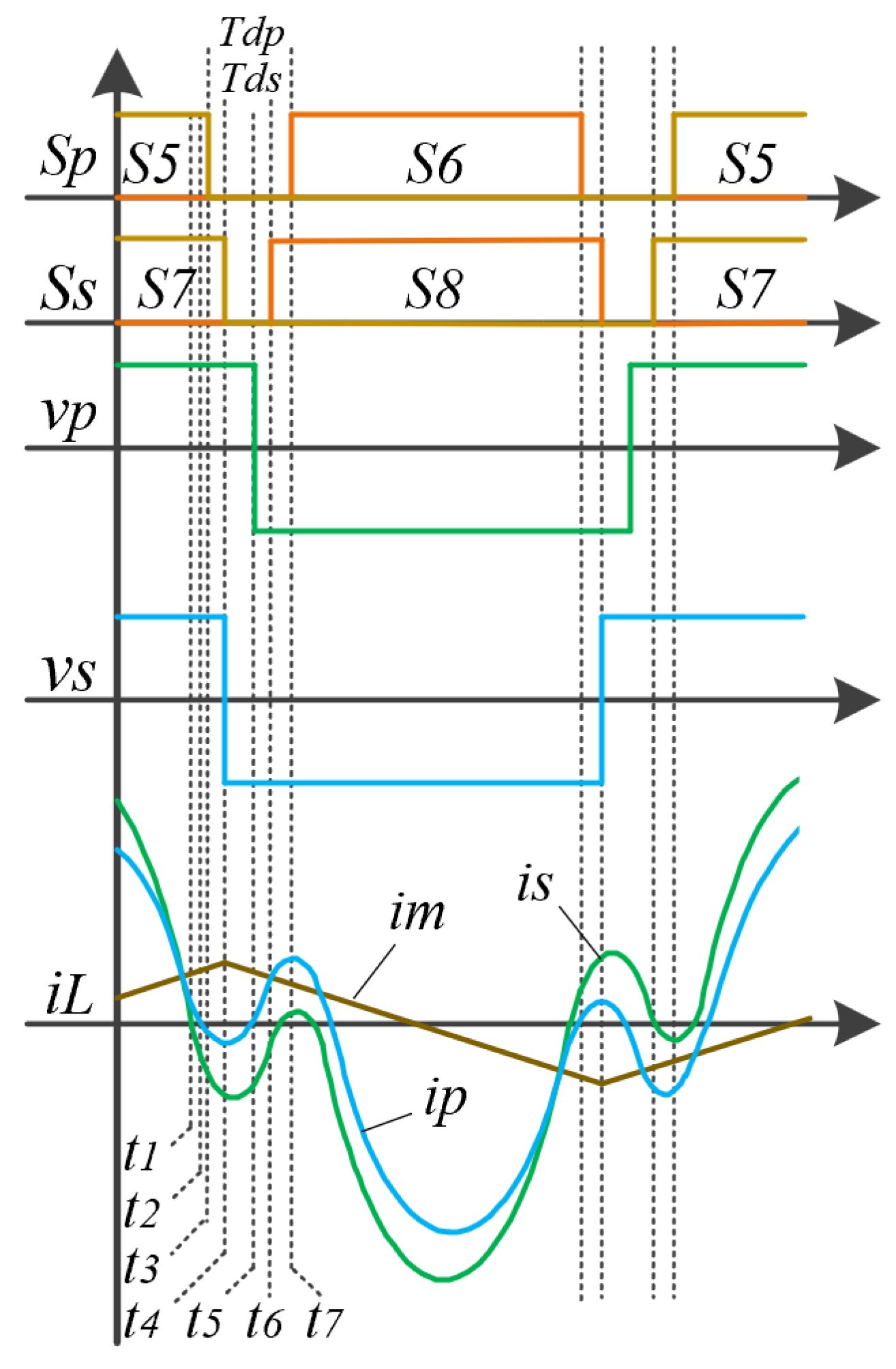
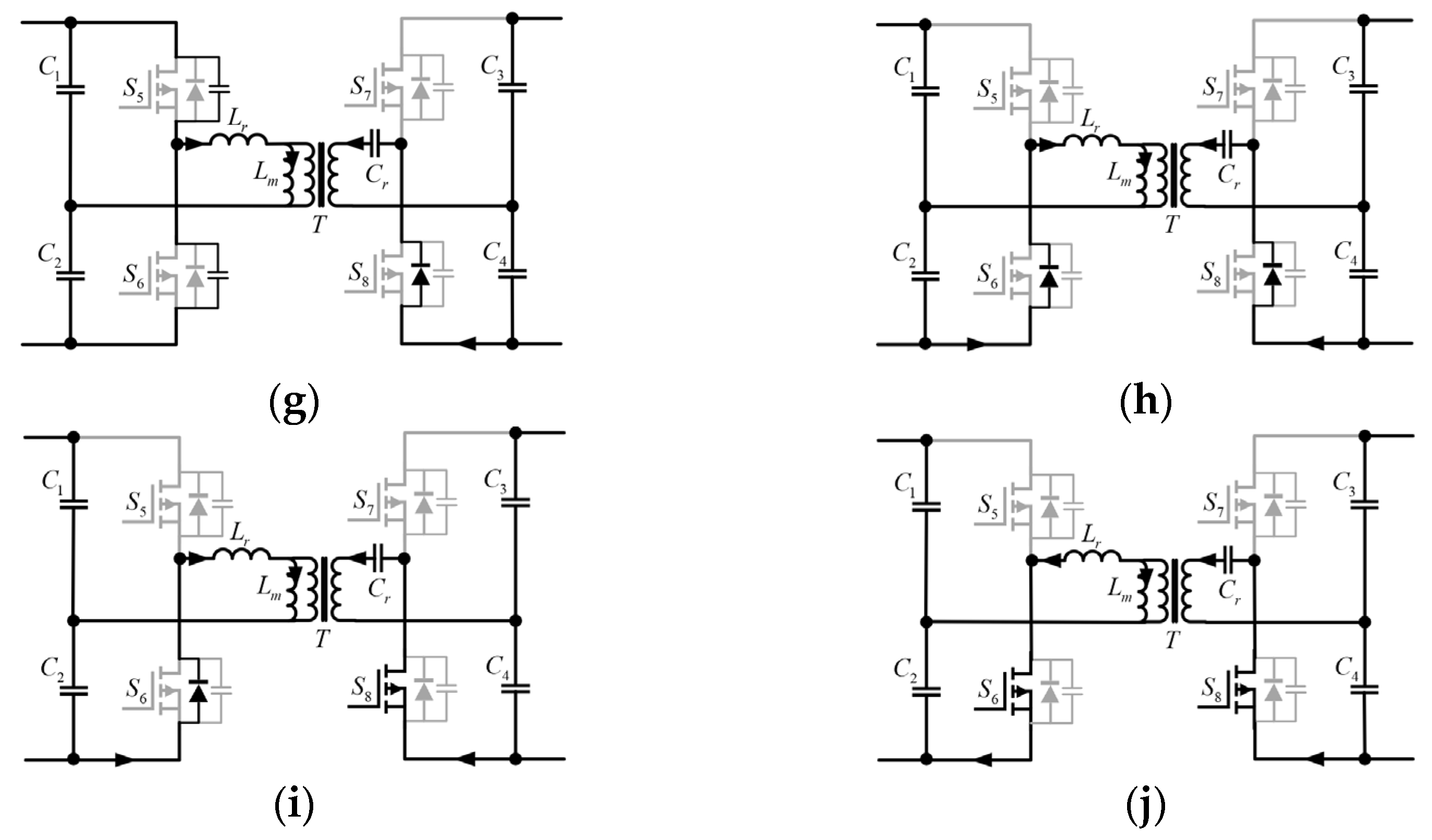
3.1. ZVS Analysis
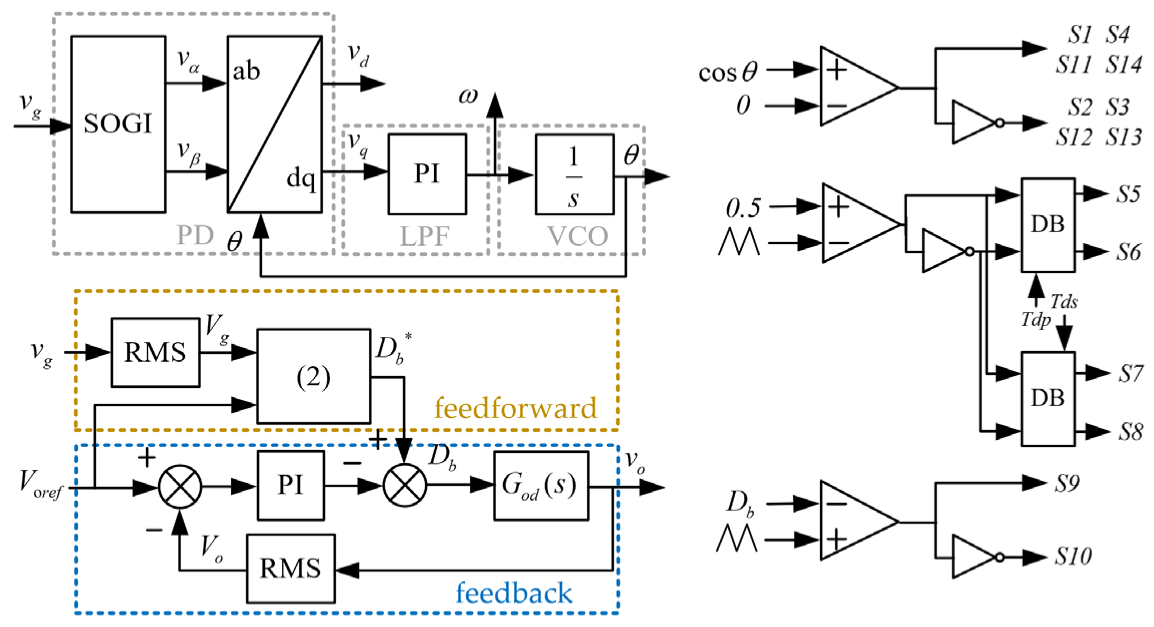
3.2. Control Scheme
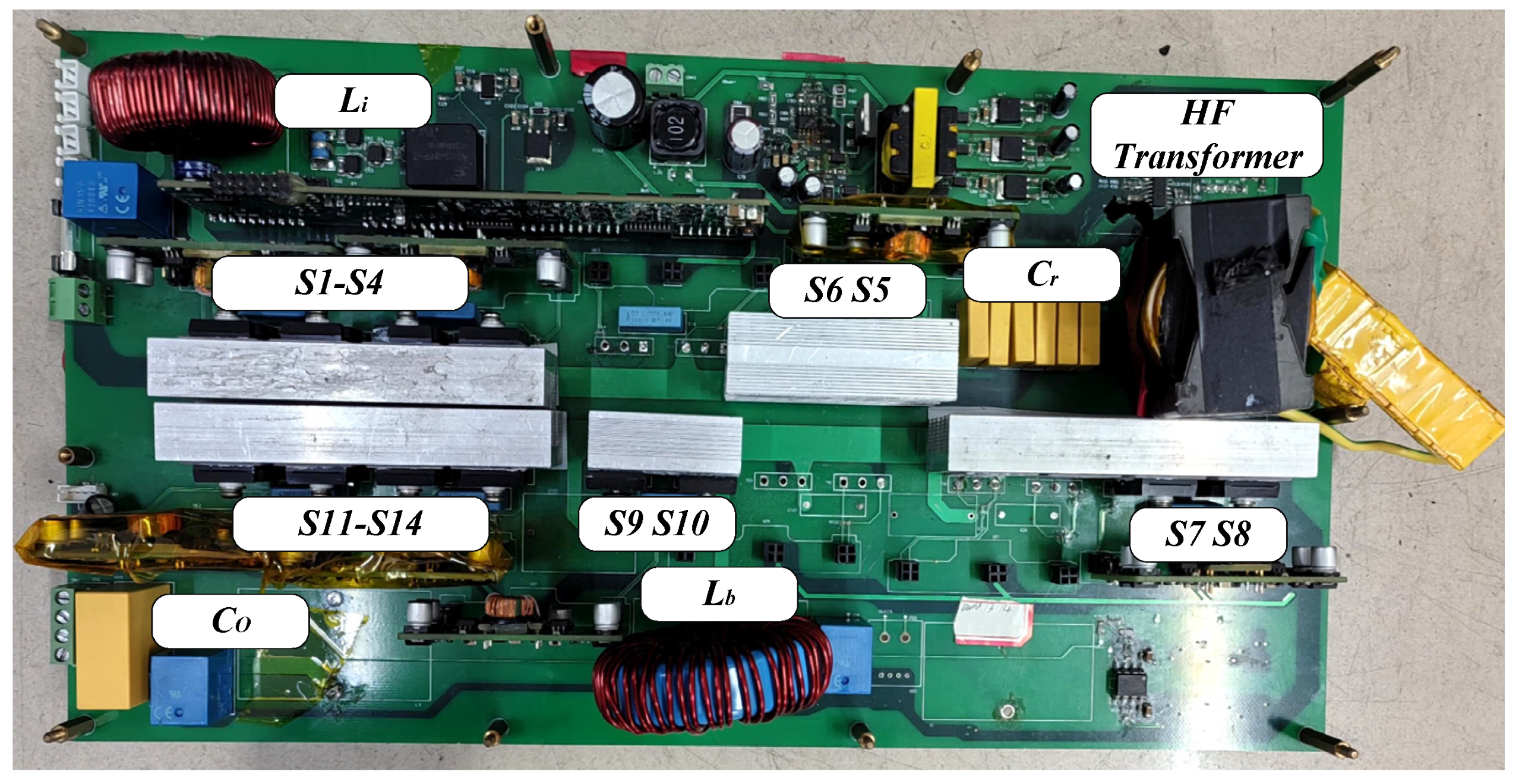
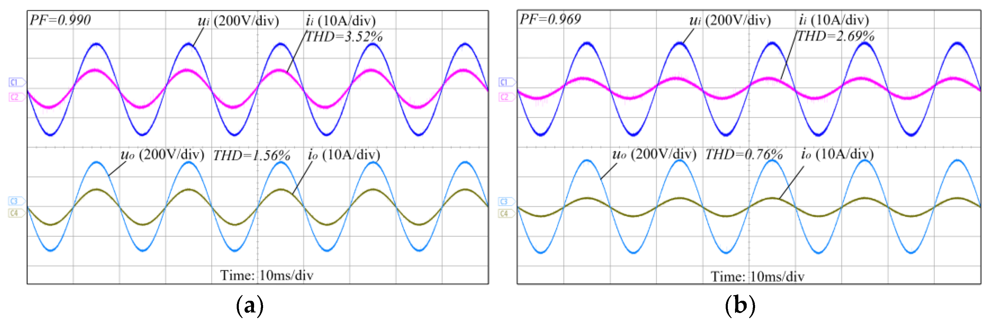
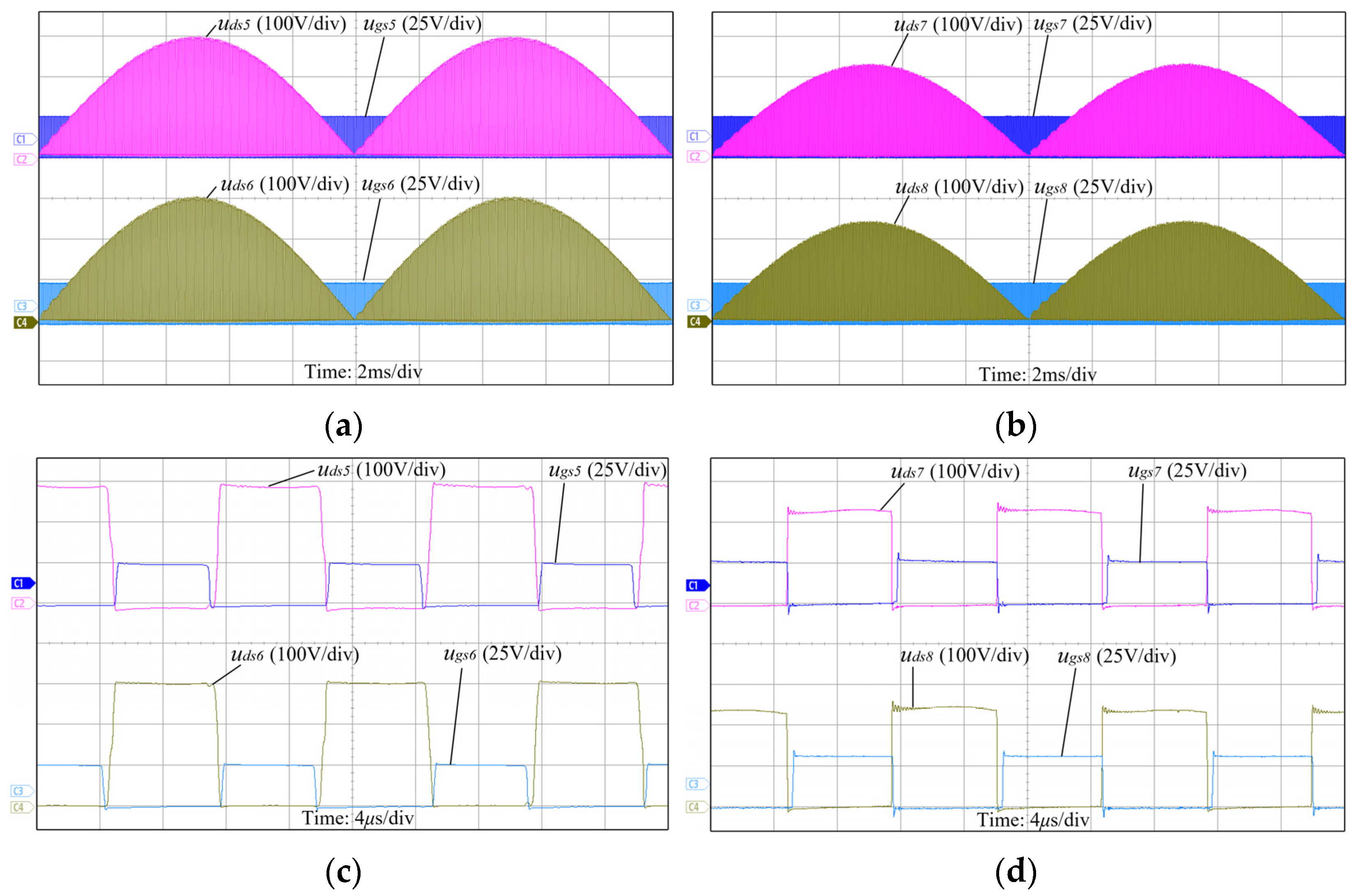
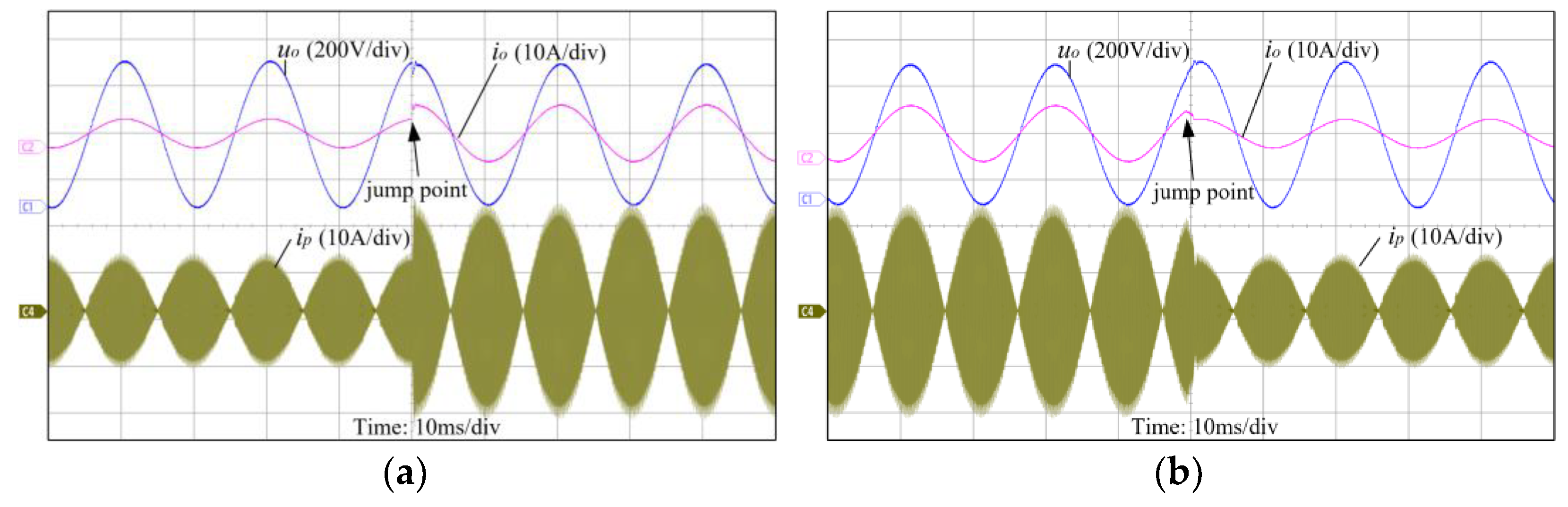
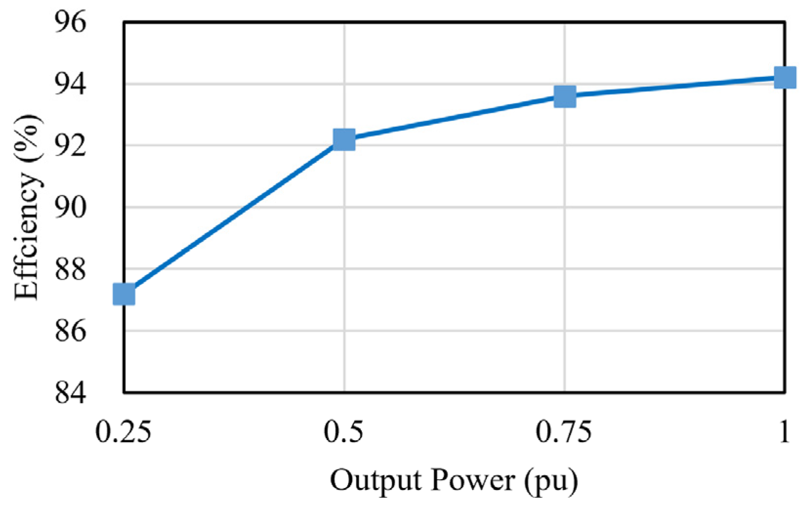
4. Experimental Results
5. Conclusions
Author Contributions
Funding
Data Availability Statement
Conflicts of Interest
References
- Huber, J.E.; Kolar, J.W. Applicability of Solid-State Transformers in Today’s and Future Distribution Grids. IEEE Trans. Smart Grid 2019, 10, 317–326. [Google Scholar] [CrossRef]
- Menzi, D.; Yang, A.; Chhawchharia, S.; Coday, S.; Kolar, J.W. Novel Three-Phase Electronic Transformer. IEEE Trans. Power Electron. 2024, 39, 5027–5033. [Google Scholar] [CrossRef]
- Lesniewska, E.; Roger, D. Selection of the Winding Type of Solid-State Transformers in Terms of Transmitting the Greatest Possible Power in the Frequency Range from 500 Hz to 6000 Hz. Energies 2023, 16, 6528. [Google Scholar] [CrossRef]
- Zhang, J.; Li, H.; Kong, X.; Zhou, J.; Shi, G.; Zang, J.; Wang, J. A Novel Multiple-Medium-AC-Port Power Electronic Transformer. IEEE Trans. Ind. Electron. 2024, 71, 6568–6578. [Google Scholar] [CrossRef]
- Li, Z.; Pei, Y.; Liu, J.; Wang, L.; Leng, Z. Design and Optimization of the MMC-Based Power Electronic Transformer Considering Ripple Power Transfer. IEEE Trans. Power Electron. 2025, 40, 5352–5370. [Google Scholar] [CrossRef]
- Zheng, L.; Marellapudi, A.; Chowdhury, V.R.; Bilakanti, N.; Kandula, R.P.; Saeedifard, M.; Grijalva, S.; Divan, D. Solid-State Transformer and Hybrid Transformer With Integrated Energy Storage in Active Distribution Grids: Technical and Economic Comparison, Dispatch, and Control. IEEE J. Emerg. Sel. Top. Power Electron. 2022, 10, 3771–3787. [Google Scholar] [CrossRef]
- Zhang, J.; Zha, K.; Tang, X.; Yang, Y.; Li, L.; Li, J. Topology and Control Strategy of Multi-Port DC Power Electronic Transformer Based on Soft Switching. Energies 2025, 18, 400. [Google Scholar] [CrossRef]
- Elsaharty, M.A.; Luna, A.; Candela, J.I.; Rodriguez, P. A Unified Power Flow Controller Using a Power Electronics Integrated Transformer. IEEE Trans. Power Deliv. 2019, 34, 828–839. [Google Scholar] [CrossRef]
- Zhao, C.; Dujic, D.; Mester, A.; Steinke, J.K.; Weiss, M.; Lewdeni-Schmid, S.; Chaudhuri, T.; Stefanutti, P. Power electronic traction transformer—Medium voltage prototype. IEEE Trans. Ind. Electron. 2014, 61, 3257–3268. [Google Scholar] [CrossRef]
- Costa, L.F.; De Carne, G.; Buticchi, G.; Liserre, M. The smart transformer: A solid-state transformer tailored to provide ancillary services to the distribution grid. IEEE Power Electron. Mag. 2017, 4, 56–67. [Google Scholar] [CrossRef]
- Shrivastava, A.; Azarian, M.H.; Pecht, M. Failure of Polymer Aluminum Electrolytic Capacitors Under Elevated Temperature Humidity Environments. IEEE Trans. Components, Packag. Manuf. Technol. 2017, 7, 745–750. [Google Scholar] [CrossRef]
- Komeda, S.; Fujita, H. A Power Decoupling Control Method for an Isolated Single-Phase AC-to-DC Converter Based on Direct AC-to-AC Converter Topology. IEEE Trans. Power Electron. 2018, 33, 9691–9698. [Google Scholar] [CrossRef]
- Kolar, J.W.; Ortiz, G. Solid-state-transformers: Key components of future traction and smart grid systems. In Proceedings of the International Power Electronics Conference-ECCE Asia (IPEC 2014), Hiroshima, Japan, 18–21 May 2014; pp. 18–21. [Google Scholar]
- Zhang, G.; Chen, J.; Zhang, B.; Zhang, Y. A critical topology review of power electronic transformers: In view of efficiency. Chin. Chin. J. Electr. Eng. 2018, 4, 90–95. [Google Scholar]
- Bu, Q.; Wen, H.; Shi, H.; Zhu, Y. A Comparative Review of High-Frequency Transient DC Bias Current Mitigation Strategies in Dual-Active-Bridge DC–DC Converters Under Phase-Shift Modulations. IEEE Trans. Ind. Appl. 2022, 58, 2166–2182. [Google Scholar] [CrossRef]
- Olowu, T.O.; Jafari, H.; Sarwat, A. Voltage-Controlled Series Resonant DC-DC Converter for Solid State Transformer Applications. In Proceedings of the 2021 IEEE Transportation Electrification Conference & Expo (ITEC), Chicago, IL, USA, 21–25 June 2021; pp. 237–241. [Google Scholar]
- Rahman, A.N.; Chen, S.K.; Chiu, H.J. Single Phase AC-AC Solid State Transformer based on Single Conversion Stage. In Proceedings of the 2019 IEEE Workshop on Wide Bandgap Power Devices and Applications in Asia (WiPDA Asia), Taipei, Taiwan, 23–25 May 2019; pp. 1–5. [Google Scholar]
- Qin, H.; Kimball, J.W. Solid-state transformer architecture using AC–AC dual-active-bridge converter. IEEE Trans. Ind. Electron. 2013, 60, 3720–3730. [Google Scholar] [CrossRef]
- Su, M.; Huang, J.; Wang, H.; Jiang, L.; Chen, X. Direct AC–AC Solid-State Transformer Based on Hybrid DAB. IEEE J. Emerg. Sel. Top. Power Electron. 2024, 12, 1385–1394. [Google Scholar] [CrossRef]
- Zhu, Q.; Wang, L.; Huang, A.Q.; Booth, K.; Zhang, L. 7.2-kV Single-Stage Solid-State Transformer Based on the Current-Fed Series Resonant Converter and 15-kV SiC mosfets. IEEE Trans. Power Electron. 2019, 34, 1099–1112. [Google Scholar] [CrossRef]
- Rothmund, D.; Guillod, T.; Bortis, D.; Kolar, J.W. 99% efficient 10 kV SiC-based 7 kV/400 V DC transformer for future data centers. IEEE J. Emerg. Sel. Top. Power Electron. 2019, 7, 753–767. [Google Scholar] [CrossRef]
- Zhu, Q.; Wang, L.; Zhang, L.; Huang, A.Q. A 10 kV DC transformer (DCX) based on current fed SRC and 15 kV SiC MOSFETs. In Proceedings of the IEEE Applied Power Electronics Conference and Exposition (APEC), San Antonio, TX, USA, 4–8 March 2018; pp. 149–155. [Google Scholar]
- Prakash, S.; Singh, J.K.; Behera, R.K.; Mondal, A. Comprehensive Analysis of SOGI-PLL Based Algorithms for Single-Phase System. In Proceedings of the 2019 National Power Electronics Conference (NPEC), Tiruchirappalli, India, 13–15 December 2019; pp. 1–6. [Google Scholar]
- Chambayil, A.; Chattopadhyay, S. A Single-stage Single Phase Bidirectional AC-AC Converter for Solid State Transformer Application. In Proceedings of the 2022 IEEE International Conference on Power Electronics, Drives and Energy Systems (PEDES), Jaipur, India, 14–17 December 2022; pp. 1–6. [Google Scholar]
- Da Silva, O.C.; Tofoli, F.L.; Honório, D.d.A.; Barreto, L.H.S.C.; Oliveira, D.d.S. Single-Phase Isolated AC-AC Converters Based on the Dual Active Bridge Converter. IEEE Trans. Ind. Electron. 2022, 69, 5680–5689. [Google Scholar] [CrossRef]


| Parameters | LF Transformer | HF Transformer |
|---|---|---|
| Power rating | 1 kW | 1 kW |
| Operating frequency | 50 Hz | 65 kHz |
| Magnetic Core | silicon steel | PC95 ferrite |
| Volume | 160 × 150 × 150 mm | 50 × 42 × 50 mm |
| Weight | 12.5 kg | 0.7 kg |
| Parameters | Value | Parameters | Value |
|---|---|---|---|
| Input voltage vg | 220 Vrms 50 Hz | Inductance Li | 220 μH |
| Output voltage vo | 220 Vrms 50 Hz | Inductance Lr | 6.4 μH |
| Turns ratio n | 1.2 | Inductance Lm | 320 μH |
| Capacitance C1 C2 | 2 × 2.7 μF | Inductance Lb | 470 μH |
| Capacitance C3 C4 | 2 × 2.7 μF | LLC frequency fs | 65 kHz |
| Capacitance Co | 3.3 μF | BOOST frequency fb | 20 kHz |
| Capacitance Cr | 0.9 μF | Power rating | 1 kW |
| Parameters | Proposed Topology | [19] | [24] | [25] |
|---|---|---|---|---|
| Switches | 8 in LF 6 in HF | 6 in LF 6 in HF | 12 in HF | 8 in HF |
| Input filter inductor | 220 μH | 350 μH | 500 μH | 2 × 645 μH |
| Output filter inductor | / | 385 μH | 500 μH | 2 × 645 μH |
| Output filter capacitor | 3.3 μF | 1.3 μF | N/A | 220 nF |
| DC-link capacitor | Film capacitor (2 × 2.7 μF) | Film capacitor (2 × 2 μF) | Electrolytic Capacitor | Electrolytic Capacitor (3 × 680 μF) |
| Resonant inductor | 6.4 μH | 6.16 μH | 80 μH | 108 μH |
| Efficiency | 94.2% | 92.1% | 92.8% | 91.3% |
| MOSFETs | FCH072N60F, 600 V, 52 A, 72 mΩ | FCH072N60F, 600 V, 52 A, 72 mΩ | C2M0040120D, 1200 V, 36 A, 80 mΩ | SCT3120AL, 650 V, 21 A, 120 mΩ |
| Transformer frequency | 65 kHz | 100 kHz | 100 kHz | 30 kHz |
| Power rating | 1 kW | 2 kW | 1 kW | 500 W |
| Peak voltage (per unit) | 1 | 1 | 2.25 | 2.57 |
| RMS current (per unit) | 2 | 2 | 1.6 | 1 |
Disclaimer/Publisher’s Note: The statements, opinions and data contained in all publications are solely those of the individual author(s) and contributor(s) and not of MDPI and/or the editor(s). MDPI and/or the editor(s) disclaim responsibility for any injury to people or property resulting from any ideas, methods, instructions or products referred to in the content. |
© 2025 by the authors. Licensee MDPI, Basel, Switzerland. This article is an open access article distributed under the terms and conditions of the Creative Commons Attribution (CC BY) license (https://creativecommons.org/licenses/by/4.0/).
Share and Cite
Wang, H.; Xie, S.; Yuan, L. A Single-Phase AC-AC Power Electronic Transformer Without Bulky Energy Storage Elements. Energies 2025, 18, 1769. https://doi.org/10.3390/en18071769
Wang H, Xie S, Yuan L. A Single-Phase AC-AC Power Electronic Transformer Without Bulky Energy Storage Elements. Energies. 2025; 18(7):1769. https://doi.org/10.3390/en18071769
Chicago/Turabian StyleWang, Hui, Shuyang Xie, and Liang Yuan. 2025. "A Single-Phase AC-AC Power Electronic Transformer Without Bulky Energy Storage Elements" Energies 18, no. 7: 1769. https://doi.org/10.3390/en18071769
APA StyleWang, H., Xie, S., & Yuan, L. (2025). A Single-Phase AC-AC Power Electronic Transformer Without Bulky Energy Storage Elements. Energies, 18(7), 1769. https://doi.org/10.3390/en18071769