Article

Research on the Magnetic Integration of Inductors for High-Power DC Transformers—A Case Study on Electric Roadways

1
College of Mechanical and Vehicle Engineering, Hunan University, Changsha 410012, China
2
CRRC Zhuzhou Electric Locomotive Research Institute Co., Ltd., Zhuzhou 412001, China
*
Author to whom correspondence should be addressed.
Energies 2025, 18(7), 1859; https://doi.org/10.3390/en18071859
Submission received: 22 February 2025 / Revised: 19 March 2025 / Accepted: 26 March 2025 / Published: 7 April 2025
(This article belongs to the Section F: Electrical Engineering)

Abstract

:
With the growth of renewable energy, electrified highways can efficiently utilize green energy such as solar and wind for EVs, promoting sustainable transportation and carbon reduction, and accelerating the transition to a greener future. For high-power DC/DC converters in electrified roadways, a lightweight and compact design is crucial, but inductors limit progress. Therefore, this study focuses on the magnetic integration of DC/DC chopping inductors. It first selected and optimized the decoupled magnetic integration form, initial electromagnetic parameters, and core sizes based on circuit topology and device specifications, using core loss and thermal rise models. Then, it determined the optimal winding turns ratio according to the air gap and magnetic resistance ratio, obtaining the final design with insulation considered. The design was verified through finite-element simulation, prototype manufacturing, and testing, and an improved optimization with interleaved parallel control was proposed. Results indicate that magnetic integration reduces the inductor’s volume by 7.93% and footprint by 38.62%, facilitating the lightweight and compact design of relevant magnetic components. With interleaved parallel control, the integrated inductor’s volume can be reduced by 19.74%, significantly decreasing the volume and mass of the chopping inductor.

1. Introduction

With the urgent need for global climate change mitigation and low-carbon energy transition, the electrification of transportation, especially electrified roads, has gained increasing attention as an effective solution. Electrified roads [1,2,3], as a new mode of road transportation, are based on the core concept of utilizing high-power onboard DC sources to achieve energy transfer and kinetic energy recovery between road traction networks and freight trucks. It can directly integrate new energy power sources such as wind and photovoltaic systems into the power supply network, realizing the local consumption of new energy. This is helpful in solving the problems of abandoning wind and light and reducing the grid fluctuation caused by the integration of renewable energy and the power loss caused by long-distance transmission. In addition, during the vehicle driving process, compared with fuel vehicles, it can significantly reduce the emissions of carbon dioxide, particulate matter, and other pollutants, which is of great significance in improving the ecological environment and dealing with climate change. Taking the 100 km transportation scenario as an example, the carbon dioxide emissions in the power consumption process of 49 ton ERS vehicles per hundred kilometers are 62% lower than that of the carbon dioxide emissions in the diesel consumption process of traditional fuel heavy-duty trucks with the same mass per hundred kilometers. According to [4], if green electricity is used, the emission reduction intensity is greater, and the emission reduction efficiency reaches 98.2%. Therefore, with their significant advantages of being green and low-carbon, energy-efficient, cost-effective, and capable of intelligent grouping, electrified roads are considered a forward-looking and disruptive technology that could potentially trigger a transformation in the transportation industry [5].
In the onboard environment, DC power supplies are highly sensitive to lightweight, compact design; high power density; and efficiency. Typically, magnetic components such as inductors and transformers account for about 30% of the total volume, weight, and power consumption in power modules, with this proportion potentially being higher in high-frequency and modular power supplies, making them key components with a high optimization demand. Furthermore, to enhance adaptability to the working environment, high-power supplies need to meet both wide input voltage regulation and electrical isolation requirements. This has led to the widespread use of a two-stage architecture consisting of regulation and isolation stages in modular power supplies [6,7,8].
The isolation stage often employs an LLC resonant converter, which operates in an open-loop state at the highest efficiency point to achieve high power density and efficiency. The regulation stage typically uses pulse-width modulation (PWM) converters, such as Buck or Boost converters, known for their wide voltage regulation range and simple control. However, this results that the magnetic components in the regulation stage must endure more stringent operating conditions under closed-loop control, necessitating larger margins in conventional discrete magnetic component design and arrangement, thereby increasing overall volume, weight, and cost.
Increasing the operating frequency is a common method employed to reduce the size and improve the efficiency of magnetic components. However, the increased core losses due to higher frequencies present a significant challenge to lightweight design, and researchers often consider frequency limits at the system level early in the design phase, making it difficult to achieve lightweight design simply by increasing the frequency. Integrated Magnetics (IM) is alternative effective approach to reduce the number and overall size and weight of magnetic components. The core idea is to organically integrate multiple discrete magnetic components (DM) into a single unit, cleverly utilizing the relationships between current and magnetic flux through magnetic circuit design and control strategies, thereby optimizing the design from an overall perspective to suppress ripple, reduce losses, and minimize overall size and weight [9,10,11,12,13,14,15,16]. Reference [9] proposed a dual-inductor coupled magnetic integration design that can reduce output current ripple or even achieve zero ripple when designed appropriately. However, direct coupled magnetic integration requires close alignment with circuit operating modes, resulting in high design complexity and susceptibility to actual operating conditions.
References [10,11,12] offered a decoupled magnetic integration design by providing a low magnetic reluctance magnetic circuit. This method is simple and effective, significantly reducing the correlation between magnetic integration design and circuit operating modes, which is beneficial for the distribution design of modular power systems. This decoupled magnetic integration approach considers the optimization margin of the magnetic core and multiple windings from an overall perspective, achieving lightweight and compact design. Additionally, for parallel topologies, interleaved parallel control technology can effectively reduce ripple stacking through phase shifting, potentially further enhancing the advantages of magnetic integration in terms of ripple suppression [12], loss reduction, and size and weight reduction.
Based on the high-power DC power supply topology for electrified roads [17,18,19], this paper employs magnetic integration and finite element technology to obtain a dual-inductor magnetic integration solution and completes long-term testing of the magnetic integration prototype to validate the solution, effectively reducing the overall volume and weight of the dual-slicing inductors for electrified roads. Furthermore, this paper also proposes a magnetic integration solution combined with interleaved parallel control, which can further enhance the lightweight and compact design of slicing inductors for electrified roads.

2. Topology of the DC Transformer for Electrified Roads

The circuit topology and basic parameters of the DC transformer power supply module for electrified roads are shown in Figure 1 and Table 1. The main topology consists of two Buck TL-LLC units connected in an ISOP configuration. Given the context of high-power and high-voltage operation, a two-stage power supply architecture with a combination of regulation and isolation stages is used.
As shown in Figure 1, V i n and C i n represent the value of input voltage and capacitor, respectively; V o u t and C o u t represent the value of output voltage and capacitor, respectively; Q 1 Q 4 are the main switching transistors in the regulation stage; and L z 1 and L z 2 are the chopping inductors in the two branches.
The typical operating waveforms of the regulation stage Buck converter are shown in Figure 2, where V G S _ Q 1 and V G S _ Q 4 are the drive signals for Q 1 and Q 4 , respectively, and i L z represents the chopping inductor current. By driving Q 1 and Q 4 out of phase by 180°, the effective working frequency of the chopping inductor is increased, which reduces the chopping current ripple and lowers losses.
High voltage and large power ratings make it difficult for LLC resonant circuits to adjust output voltage through frequency modulation. Therefore, the isolation stage uses open-loop control to ensure the circuit always operates at the highest efficiency point. The regulation stage, however, needs to address closed-loop control for both capacitor voltage balancing and output voltage regulation. The chopping inductor must withstand more severe operating conditions, which increases the spatial constraints of multiple discrete inductors and ultimately affects the overall size.

3. Dual Inductor Magnetic Integration Solution

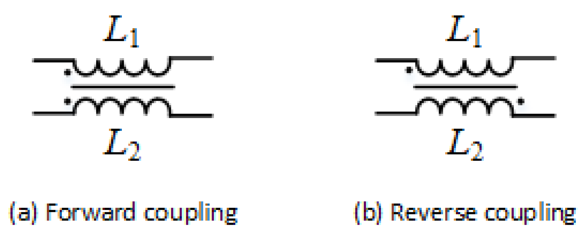
3.1. Decoupling Topology Selection

Basic topologies for inductive magnetic integration can be broadly classified into coupled and decoupled types. Coupled types connect multiple inductors at the same or different terminals. By analyzing the circuit’s operating modes and designing coupling coefficients and other related parameters, magnetic integration is achieved, as shown in Figure 3.
The decoupled type achieves multi-inductor integration and magnetic flux decoupling through flux analysis and magnetic circuit design, thereby avoiding the impact of circuit conditions on magnetic integration devices. Considering the operational conditions, a low reluctance magnetic circuit decoupling magnetic integration solution is used for the DC-DC converter adjustment stage chopper in electrified road applications, as shown in Figure 4. Based on Ampere’s circuital law and electromagnetic similarity, its corresponding equivalent magnetic circuit diagram is shown in Figure 5, where N L represents the magnetomotive force generated by the winding; R m represents the magnetic reluctance; and ϕ represents the magnetic flux in the magnetic circuit. Due to the presence of the low reluctance central leg path, the dual inductor magnetic flux is decoupled, and the desired inductance can be achieved by the simple adjustment of the core side leg air gap. Additionally, distributing the air gap across the upper and lower yokes reduces magnetic flux diffusion effects. This solution is simple and effective, and it facilitates the optimization of the design margins, insulation design, and overall spatial layout.

3.2. Magnetic Integration Inductor Design

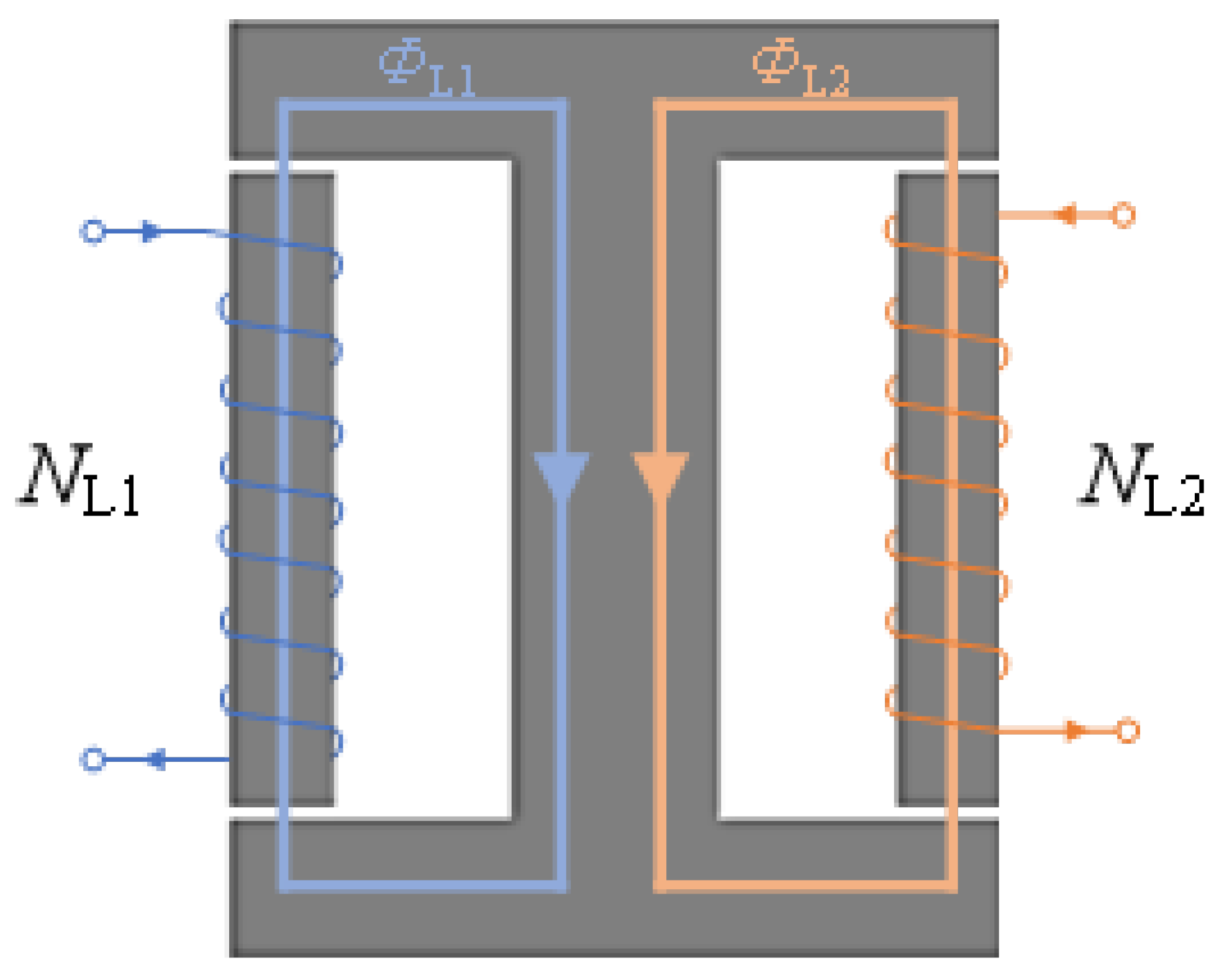
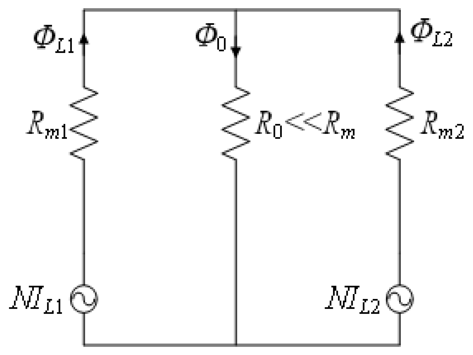
3.2.1. Basic Principles

Based on the electrical characteristics of inductors and Faraday’s electromagnetic induction formula, the basic inductor formulas can be derived, as shown in Equations (1) and (2). To avoid magnetic flux saturation, design estimates are typically made using the peak current and peak magnetic flux density.
u = L d i d t u = d ϕ d t = N A e d B d t
I × L = N × A e × B
where I denotes the current of the inductor, L represents inductance, N represents the inductor winding turns, A e represents the core cross-sectional area, and B represents the magnetic flux density.
Since the inductor windings need to be wound around the core, the core window must accommodate all the turns. This is expressed by Equation (3) as follows:
I r m s × N = A w × k u × J
where I r m s is the root mean square (RMS) value of the inductor current, A w is the window area of the magnetic core, k u denotes the winding fill factor, and J is the winding current density.
Combining Equations (2) and (3), the product of the inductance core area, which characterizes the size of the inductor core, can be obtained as shown in Equation (4). In practical engineering, core dimensions and wire specifications can vary significantly. Using this equation for the initial selection of the inductance core is beneficial for engineering design and provides a reference basis for subsequent iterative optimization.
A P = A w × A e = I r m s × I p k × L k u × J × B p k
where I p k is the peak inductor current, and B p k is the selected peak magnetic flux density.

3.2.2. Design Specifications and Boundary Conditions

Considering the operating conditions of onboard systems and the overall power supply system, the basic technical specifications for the chopper inductor of the DC-DC converter used in electrified roads are as shown in Table 2.
The isolation stage of the DC-DC converter for electrified roads employs an LLC resonant circuit. During operation, the resonant state results in a low equivalent impedance, and any abnormalities in the control stage can easily impact the terminal battery pack. Therefore, the inductor in the adjustment stage must have high stability to avoid sudden drops in the inductance value due to core saturation. The technical specifications also require a saturation current 1.5 times the rated value.
To address this, the selection of magnetic materials is particularly important. Iron-silicon, a magnetic material widely adopted in the field, is characterized by a relatively high magnetic permeability.This inherent property allows it to achieve a higher inductance value, playing a crucial role in magnetic-related applications. Moreover, its low iron-loss characteristic is conducive to improving the efficiency of electrical devices and reducing heat generation, which is particularly beneficial for the stable operation of equipment. In addition, the silicon steel sheet demonstrates outstanding processing performance, allowing for easy shaping and fabrication according to various design requirements. Notably, given the current maturity of its production process, it is possible to effectively control costs.
Based on the above reasons, iron-silicon alloy is chosen as the core material. This magnetic material offers low hysteresis loss, high saturation flux density (typically above 1.5 T), excellent over-saturation stability, and good DC bias characteristics. An initial peak magnetic flux density (Bpk) of 1.1 T is set.
For high-power inductors, the current density J should be less than 3 A/mm2 under normal cooling conditions. Considering the rated parameters of the DC-DC converter and the environmental temperature limitations, a design margin is included, and an initial current density of 2 A/mm2 is selected. The winding fill factor (ku) is chosen as 0.6, resulting in a calculated core area product (AP) of 3.068 × 10 6 m2. The actual core AP value should be greater than this calculated value. It is important to note that these parameters are initial values and will need to be adjusted iteratively based on the actual conditions.
At high frequencies, winding losses in magnetic components primarily arise from the skin effect and proximity effect, with the latter being dominant. Multi-layer windings significantly exacerbate the proximity effect. Therefore, for high-frequency magnetic core components, it is advisable to use flat copper wire or litz wire instead of multi-layer windings, and the core window size should be adjusted accordingly. Additionally, magnetic integration design requires a high degree of flexibility in core shape, so iron-silicon strips are used to construct the core. Under the current mature processes, the length of high magnetic permeability iron-silicon strips is typically less than 130 mm. Based on the AP value, four strips of 1.75 × 2 × 120 mm iron-silicon are preliminarily selected and stacked to form the magnetic leg.

3.2.3. IGSE Loss Model

As the operating frequency rises, the core loss inevitably increases in tandem. This increase in core loss, in turn, triggers a corresponding elevation in temperature. Temperature fluctuations have a substantial impact on both the hysteresis loss and eddy—current loss within the magnetic core. Notably, high temperatures frequently lead to an upsurge in hysteresis loss and an aggravation of the eddy—current loss. Additionally, they typically cause the magnetic permeability to decrease.
Moreover, upon magnetic integration, high-level integration results in a marked increase in heat generation. This amplified heat production makes the magnetic core more susceptible to reaching the saturation state. Once the saturation of the magnetic core occurs, the magnetic flux distribution becomes distorted. As a consequence, the magnetic flux generated by the coils of the two side legs no longer primarily flows through the central leg as expected. This deviation from the desired flux path disrupts the normal functioning of the magnetic integration system, thus reducing its efficiency and reliability.
As has been mentioned above, the precise calculation of core loss holds pivotal importance for analyzing the associated temperature rise. Conventional approaches to core loss calculation mainly encompass the empirical formula method and the loss separation method, as elaborated in references [20,21]. In reference [22], an accurate model for ferrite core loss is put forward, along with a prediction methodology grounded in small-sample transfer learning. The model presented in reference [23] has the capacity to replicate the inductive behavior of ferrite power inductors up to the saturation regime, all the while considering the influence of core temperature.
Due to the complexity of the core loss mechanisms and the lack of thorough understanding, existing theoretical models for core losses based on magnetization processes and loss mechanisms either require numerous experimental or empirical parameters or have low accuracy and are difficult to apply in practice. Currently, both manufacturers and researchers commonly use empirical models to calculate core losses. Among these, the Improved Generalized Steinmetz Equation (IGSE) has become one of the most widely used models due to its high precision and broad applicability [19].
The basic formula for the IGSE model is given in Equation (4). Based on this fundamental model and considering the topology and operating modes shown in Figure 1, a calculation model for the core loss of the DC-DC converter in electrified roads has been derived, shown in Equation (5), as follows:
P v = 1 T 0 T k i d B ( t ) d t α Δ B β α d t k i = C m ( 2 π ) α 1 0 2 π c o s θ α 2 β α d θ
P v = 2 β D 1 α + ( 1 D ) 1 α ( 2 π ) α 1 0 2 π c o s θ α 2 β α d θ C m f α B a c β
where P v represents the core loss per unit volume; f is the operating frequency; Δ B is the peak-to-peak magnetic flux density; B a c is the AC component of the magnetic flux density; C m , α , and β are the empirical core loss coefficients that can be obtained from the manufacturer’s handbook; and D denotes the duty cycle.

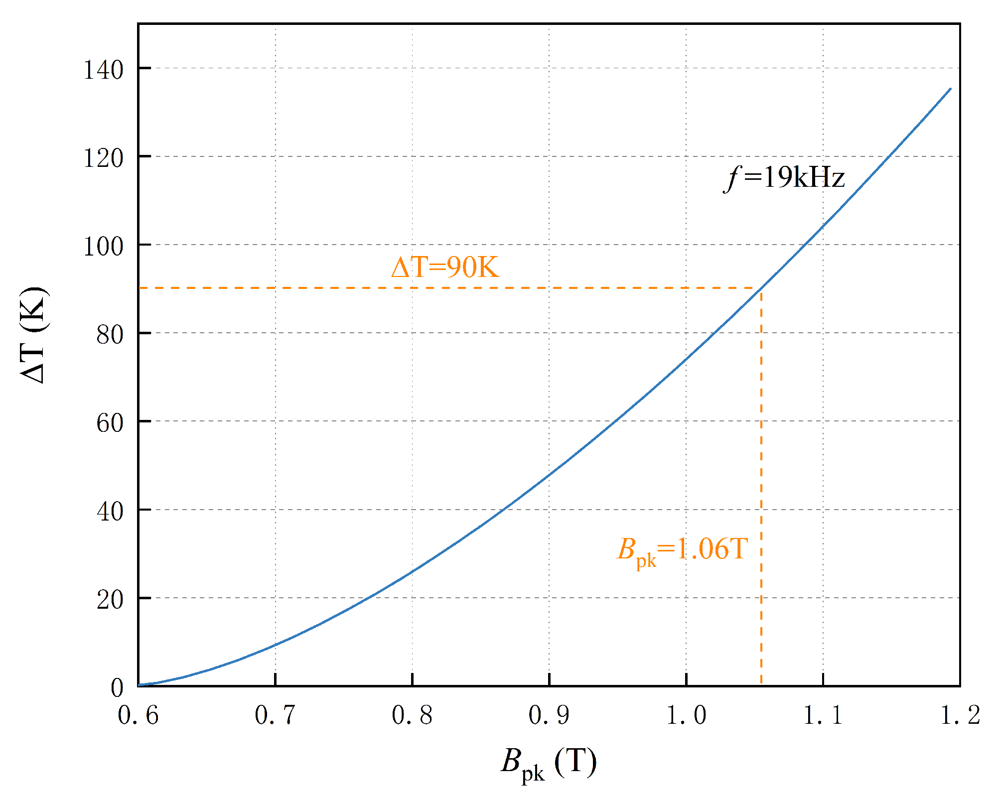
3.2.4. Temperature Rise Magnetic Flux Density Limitation

To balance model accuracy and complexity, core manufacturers have studied the relationships between the thermal resistance of magnetic devices and the core volume through fitting, as shown in Equation (7). Although this formula is primarily intended for natural convection cooling and may not be highly accurate, it can be used for the preliminary estimation of the temperature rise caused by core losses. This temperature rise can then be used to determine the maximum allowable magnetic flux density at a fixed frequency.
Δ T = P t o t A t 0.833
where P t o t represents the total loss, A t is the surface area, and Δ T denotes the temperature rise of the magnetic device.
Based on the AP value, the estimated volume of the magnetic integration inductor is approximately 1766 cm2. The total loss of the magnetic device is the sum of core losses and winding losses. Based on the AP value and prior experience, by appropriately selecting the number of turns and current density, the ratio of winding losses to core losses can always be maintained within an optimal loss ratio of β / 2 ± 10 % . For estimating the temperature rise, the loss ratio is taken as β / 2 . The relationship between magnetic flux density and temperature rise is calculated and shown in Figure 6.
As shown in the figure, without any cooling measures, at an inductor operating frequency of 19 kHz, considering an ambient temperature of up to 65 °C, and using Class F insulation materials, the peak magnetic flux density must be below 1.06 T to ensure that the maximum temperature rise is less than 90 K. It is important to note that this maximum temperature rise is calculated under the worst-case cooling conditions. With the appropriate cooling measures, the actual temperature rise will be lower than this value. The estimated temperature rise is used only to constrain the selection of the operating magnetic flux density.

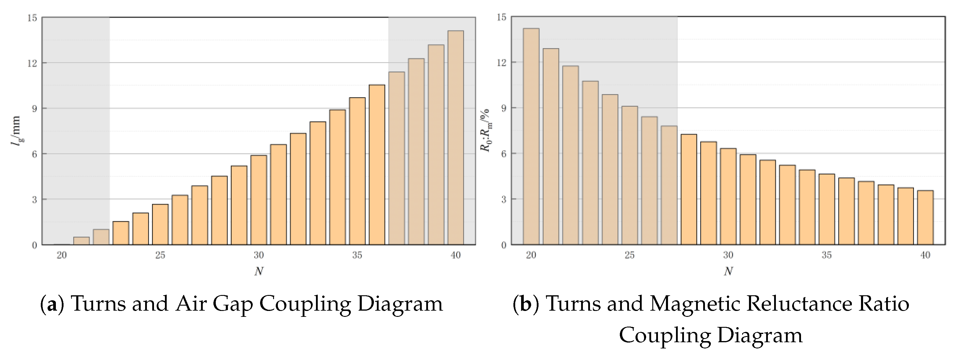
3.2.5. Selection of Winding Turns

When the core size is essentially determined, the only degree of freedom in selecting the winding turns to achieve the required inductance value is the air gap. This can be expressed by Equation (8) as follows:
L = μ c N 2 A e μ l g + l c
where μ c is the core’s magnetic permeability, μ is the relative permeability of the core with respect to vacuum, l g is the air gap length, and l c is the length of the equivalent magnetic circuit of the core.
To minimize the mutual influence of magnetic flux between the side legs in a decoupled magnetic integration scheme, the magnetic reluctance of the side legs with air gaps should be much larger than that of the central leg (as shown in Figure 5). Combining this with the previous equation, the relationship between the number of winding turns, the air gap, and the magnetic reluctance ratio can be obtained, as illustrated in Figure 7.
In Figure 7a, cases where the air gap corresponding to the boundaries of winding turns is either too small or too large are considered unsuitable (shown in the gray area of the figure). In Figure 7b, a small number of turns results in a large magnetic reluctance ratio, which causes significant cancellation of the magnetic flux between the two side legs, making it also an unsuitable solution (shown in the gray area of the figure). After considering these factors, a winding turn count of 32 turns is selected.

3.2.6. Insulation Design

The main insulation for the magnetic device involves the insulation between the winding and the core, as well as between different windings. In addition to using epoxy resin for enhanced insulation, it is important to select appropriate insulation distances. In the magnetic integration inductor scheme discussed in this paper, since the two inductor windings are separated by the central leg of the core, the focus is on the insulation distance between the winding and the core. This includes the insulation distances between the winding and the top and bottom yokes, as well as between the winding and the magnetic leg.
Considering the voltage withstand requirements and the dielectric properties of the insulation materials, the insulation distance between the magnetic leg and the winding is set at 8 mm, with the magnetic leg covered with insulating paper. Additionally, because there is an air gap between the side legs and the top and bottom yokes, it is important to prevent extra losses at the air gap while ensuring sufficient insulation distance. Therefore, the insulation distance between the winding and the top and bottom yokes is set at 10 mm.

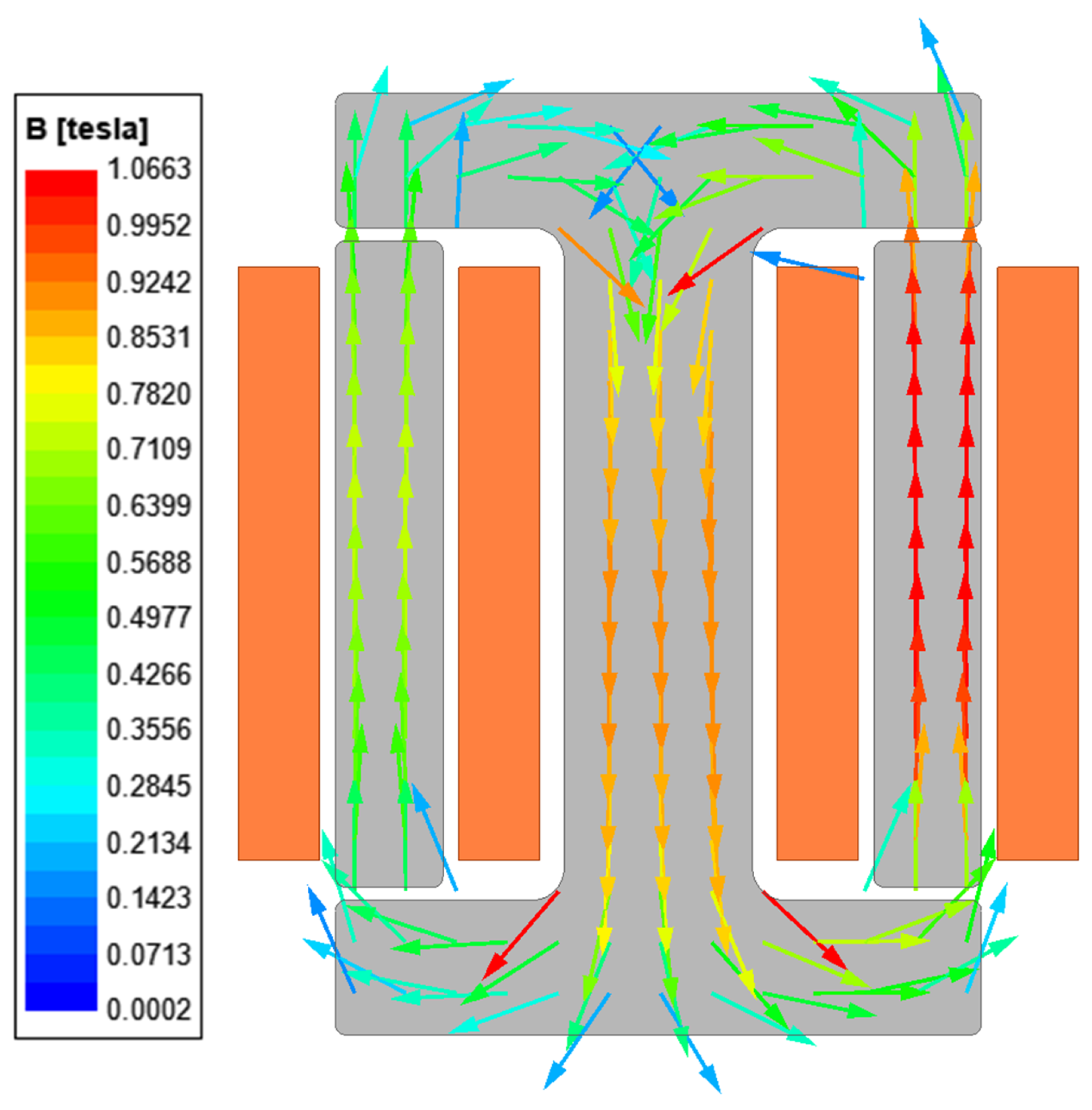
3.3. Magnetic Integration Scheme Simulation and Prototype Testing

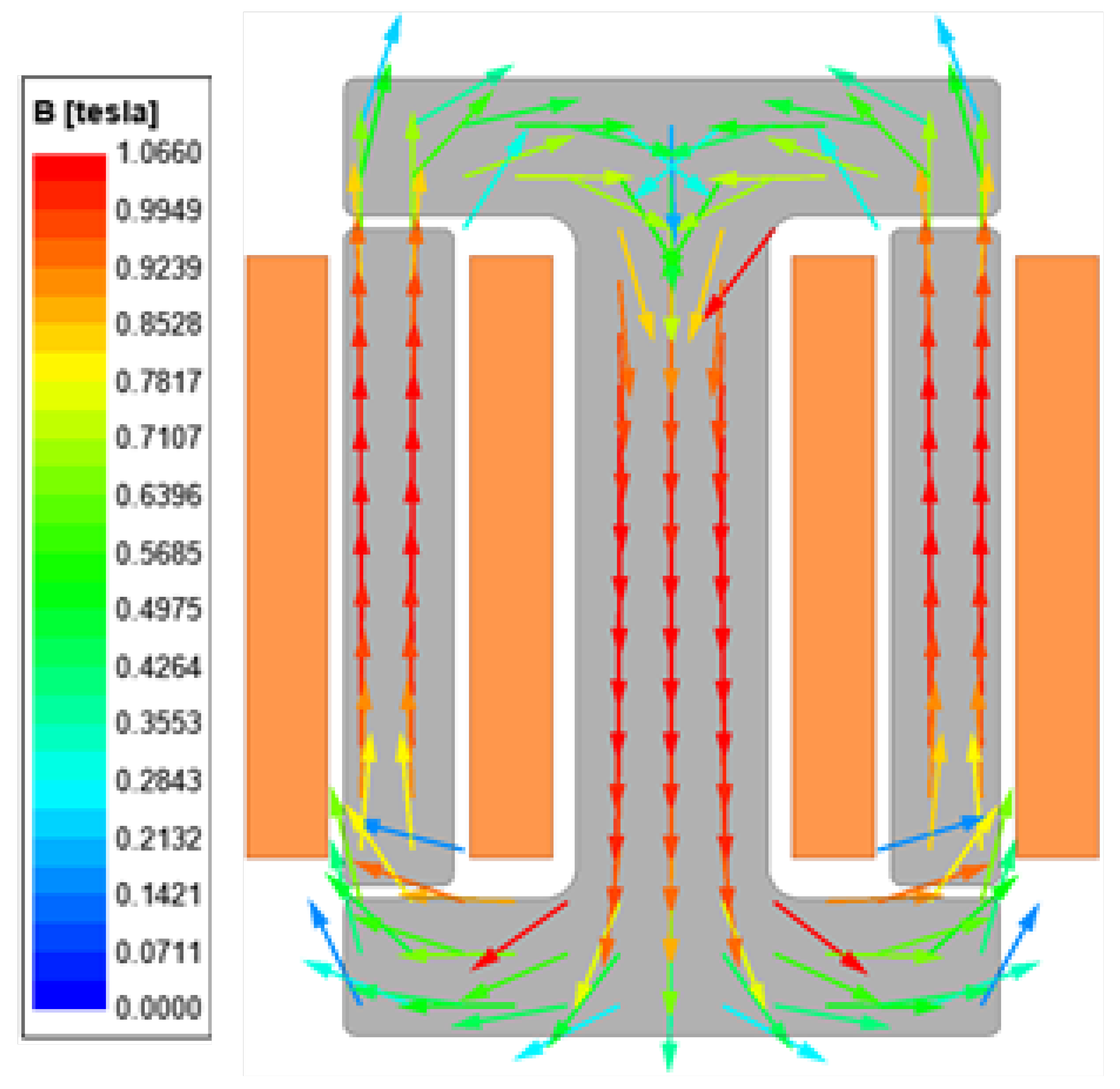
3.3.1. Magnetic Integration Scheme

Based on the previous analysis, the magnetic integration inductor scheme for the DC-DC converter in electrified roads was developed. The finite element method (FEM) was used to simulate this scheme. Under rated operating conditions, the simulation results are shown in Figure 8. The contour plot indicates that the magnetic flux direction is normal, and the peak magnetic flux density is 1.066 T, which is close to the preset value.

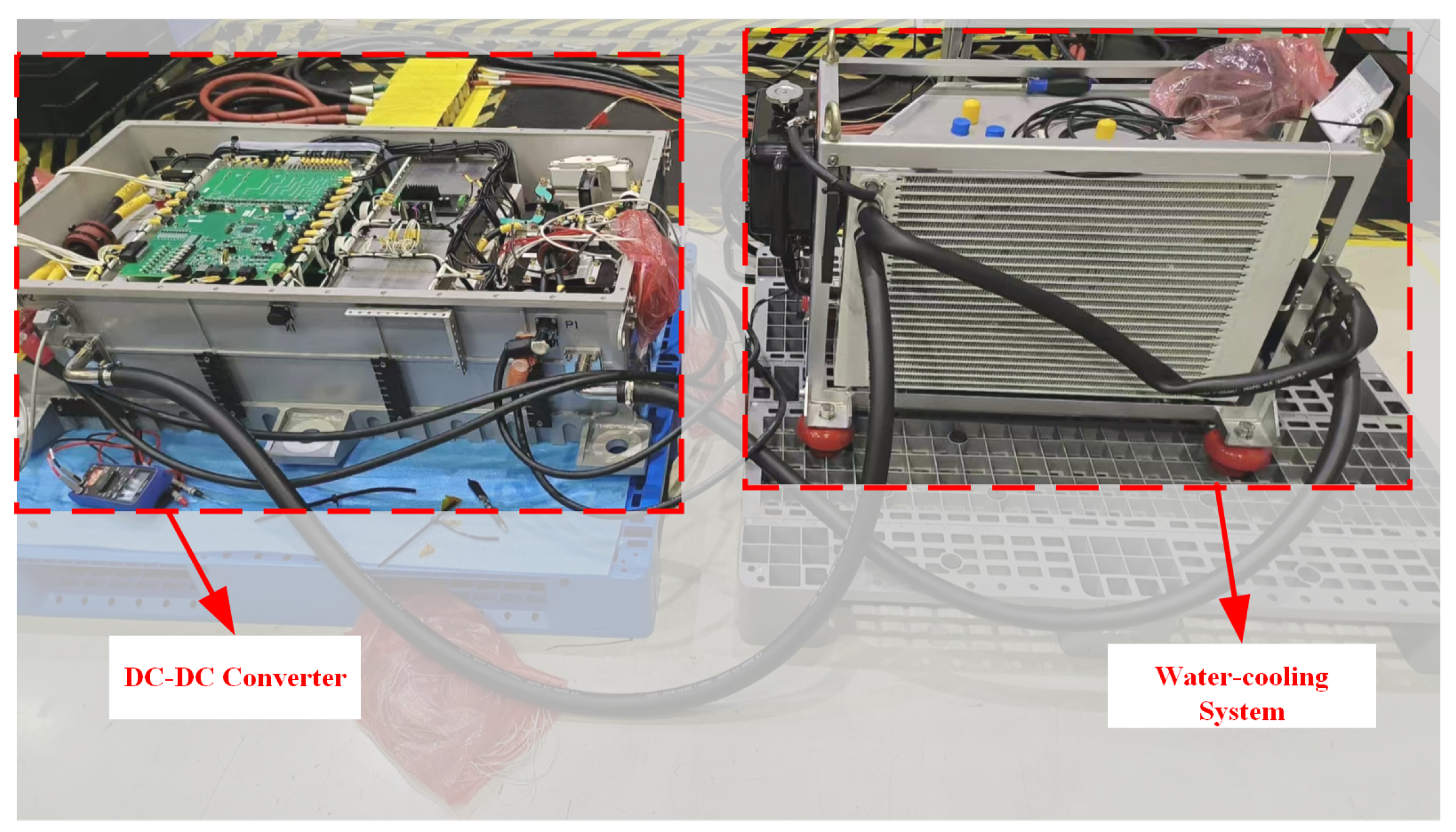
3.3.2. Prototype Testing and Verification

A prototype was manufactured based on the magnetic integration scheme, as shown in Figure 9. The prototype uses epoxy resin for encapsulation and is equipped with a water-cooled base plate for cooling and heat dissipation.
The prototype was subjected to 6600 V, 1 min dielectric strength test at the factory, with a leakage current of 1.64 mA, meeting the insulation requirements. Under rated operating conditions, the efficiency of the magnetic integration inductor was measured at 99%.
The prototype was then integrated into the DC-DC converter module for electrified roads, equipped with a water-cooling system, and tested on a test bench as shown in Figure 10. Operating under rated conditions with an output voltage adjustment set to 650 V, and due to the inductor’s location in the lower part of the module, direct measurement was challenging. Instead, the inductor current was sampled and monitored using a higher-level control system. The waveform is shown in Figure 11, indicating that the current waveform of the magnetic integration inductor is normal, with current ripple related to the specific operating mode.
After running for 3.5 h at an ambient temperature of 20 °C, the temperature rise curve of the magnetic integration inductor was obtained using embedded temperature probes, as shown in Figure 12. Based on the temperature rise data from the 3.5 h test, the maximum temperatures of the inductor core and winding under the most stringent conditions were calculated to be 127.9 °C and 120 °C, respectively. These temperatures are below the thermal insulation limit of material Class F ( 155 °C) and include a safety margin, meeting the design expectations.
Additionally, under rated operating conditions, the open-loop LLC circuit of the isolation stage was measured to determine the operating status of the entire module. The primary voltage and current waveforms of the LLC transformer are shown in Figure 13. The waveforms indicate that the input voltage is operating normally, with resonant current and step response also appearing normal. The overall system efficiency was measured to be 96.6%.

3.3.3. Comparison

The core design margin, winding structure, and spatial arrangement of multiple discrete inductors significantly impact the overall volume.
Firstly, regarding the core design margin, in discrete inductors, each core is independent, requiring both magnetic legs to have the same design margin. In contrast, in the magnetic integration scheme, the two inductors share the central leg of the core. The use of iron-silicon materials with high saturation flux density and short-term over-saturation stability allows for the optimization of the design margin for the central leg in the integrated scheme.
Secondly, concerning the winding structure and spatial arrangement, high-power inductors typically use a water-cooled base plate for heat dissipation. Compared to magnetic integration inductors, discrete inductors, despite having a lower height, require significantly more floor space, which is less favorable for practical installation. Additionally, to maintain insulation between different inductor windings, extra spacing is required, as shown in Figure 14.
Based on the specifications for the inductor in the DC-DC converter for electrified roads, the magnetic integration inductor scheme can reduce the overall volume by 7.93% and significantly decrease the footprint by 38.62%. This reduction facilitates practical application and effectively achieves a lightweight and compact design for the DC-DC converter in electrified roads.

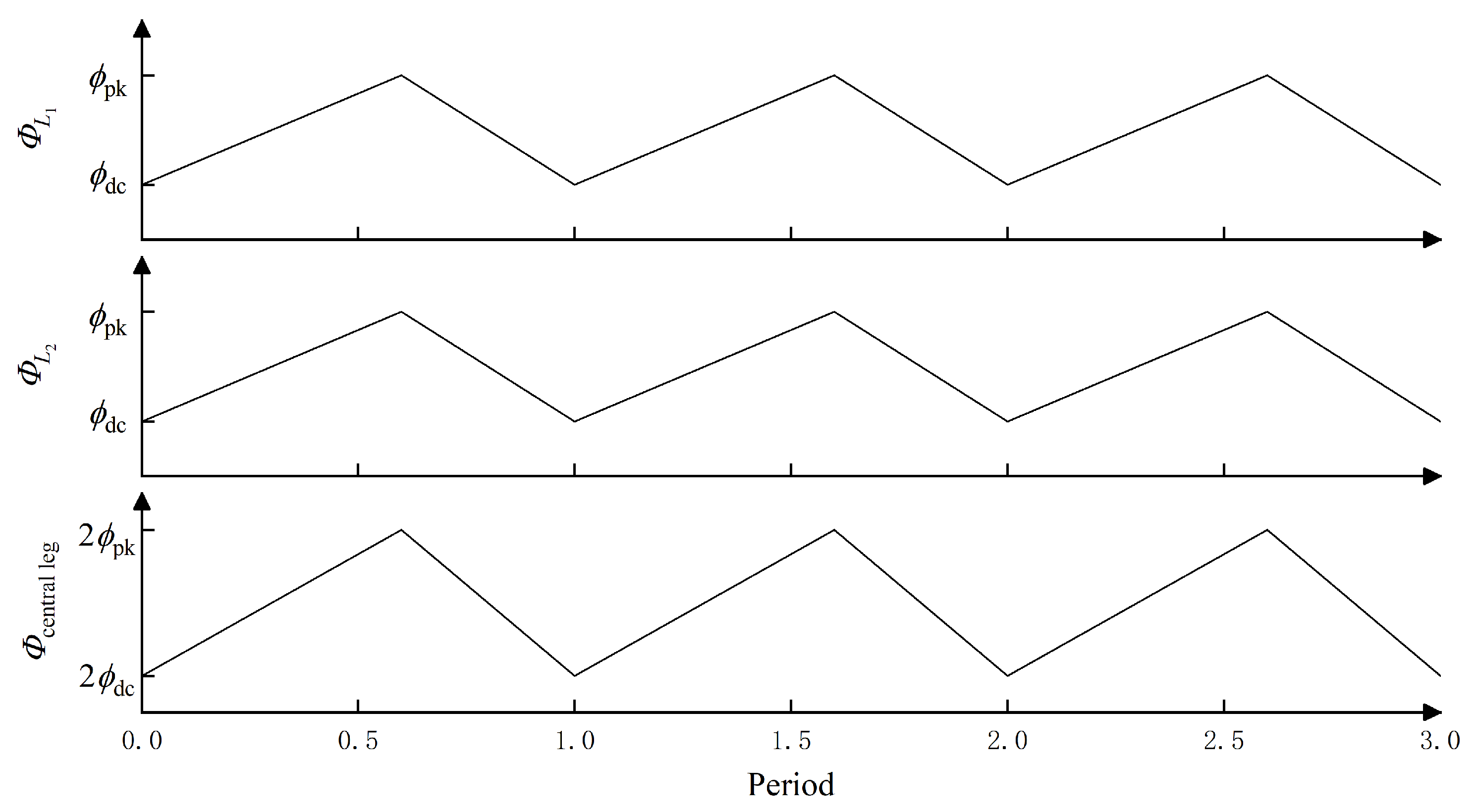
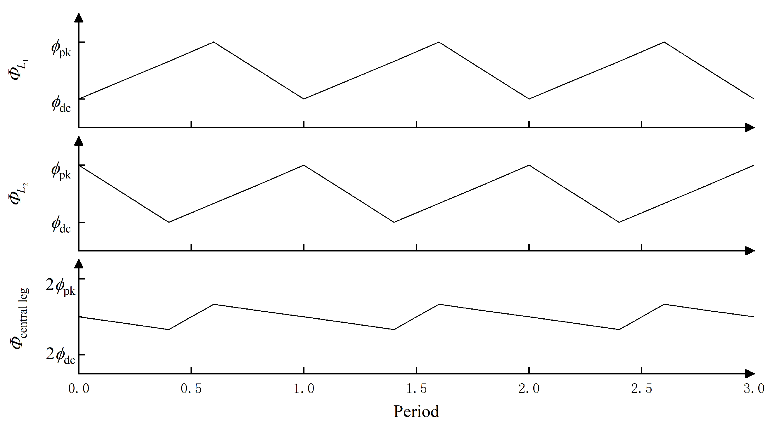
3.4. Optimization of Magnetic Integration Based on Interleaved Parallel Control

Currently, in the power module of the DC-DC converter for electrified roads, the regulation stage of the upper and lower branches operate in phase. This results in the peak magnetic flux from the side legs being simultaneously superimposed on the central leg of the core, increasing both the peak magnetic flux and ripple in the central leg. Consequently, this leads to increased core losses and necessitates a larger magnetic leg cross-sectional area, as shown in Figure 15.
For the parallel topology of the DC-DC converter power module for electrified roads, interleaved control can be used to reduce magnetic flux ripple and losses, further minimizing the volume of the magnetic integration.
Interleaved control involves staggering the flux periods of the upper and lower branch inductors based on their duty cycles. This approach prevents the simultaneous superposition of peak magnetic flux from the side legs onto the central leg, achieving a “peak shaving and valley filling” effect, which effectively reduces magnetic flux ripple in the core, as shown in Figure 16.
Furthermore, considering the coupled relationship between magnetic flux ripple, AC flux density, and core losses, as represented by Equation (9), interleaved control can effectively reduce core losses and temperature rise in the central leg, allowing for further reduction in the volume of the core’s central leg.
Δ ϕ Δ B P f e
Combining interleaved control with the finite element method, simulations were conducted for the rated operating conditions. The results are shown in Figure 17. The contour plot indicates a significant reduction in the magnetic flux density in the central leg, with the peak flux density being approximately 0.924 T.
By converting the reduced magnetic flux density in the central leg into volume reduction, the overall volume of the magnetic integration scheme can be further reduced by 12.83%. This represents a 19.74% reduction compared to discrete inductors. The specific reduction details are illustrated in Figure 18.

4. Conclusions

Based on the DC-DC converter power module for electrified roads, this paper employs magnetic integration and finite element technology to develop a dual-inductor magnetic integration scheme. The scheme has been validated through the long-term temperature rise testing of the magnetic integration prototype, and further optimization has been proposed using interleaved control. The conclusions are as follows:
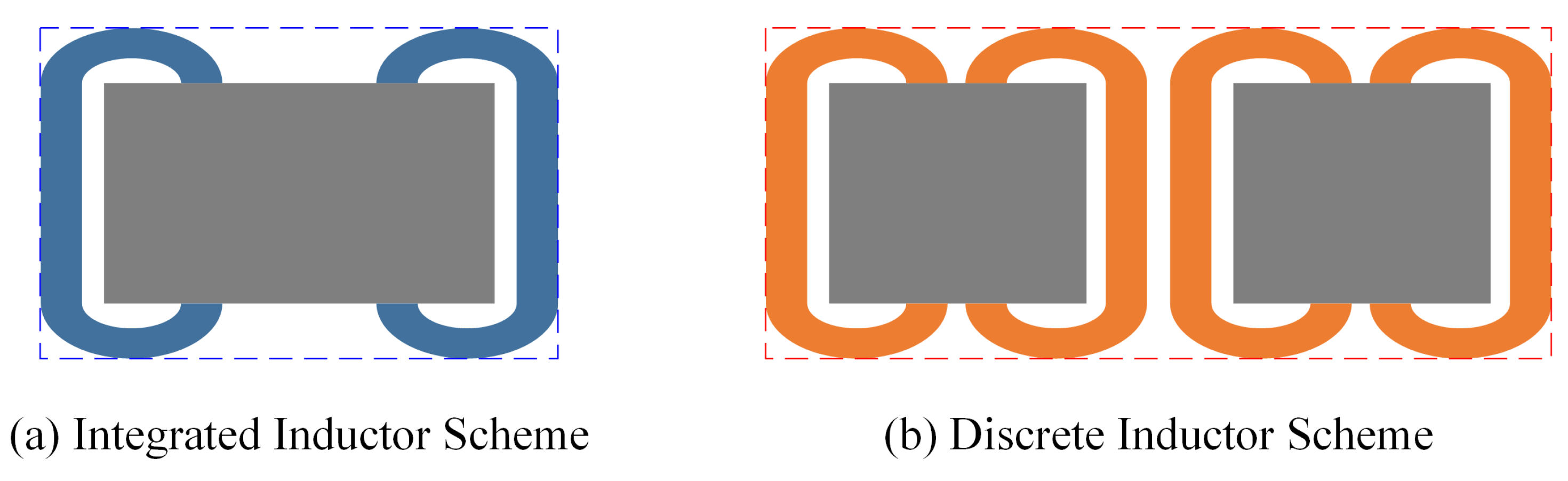
  • Volume and area reduction: The magnetic integration inductor scheme for the DC-DC converter, validated through simulations and experiments, shows that compared to discrete inductors, it can effectively reduce the overall volume by 7.93% and the footprint by 38.62%, enhancing the module’s overall lightweight and compact design.
  • Further optimization with interleaved control: Building on the magnetic integration scheme, the use of interleaved parallel control allows the magnetic integration inductor scheme to achieve a 19.74% reduction in overall volume and a 46.49% reduction in footprint compared to discrete inductors. This significantly decreases the inductor and overall module volume and mass.

Author Contributions

Conceptualization and Writing—original draft, B.L.; Writing—original draft and Writing—review & editing, H.W.; Data curation and Investigation, F.C.; Formal analysis and Visualization, W.X.; Visualization, Y.Z. All authors have read and agreed to the published version of the manuscript.

Funding

This research was funded by CRRC Zhuzhou Electric Locomotive Research Institute Co., Ltd. The APC was funded by CRRC Zhuzhou Electric Locomotive Research Institute Co., Ltd.

Data Availability Statement

No datasets were generated or analyzed during this study.

Conflicts of Interest

Authors Biyu Li, Fenglin Cai, Wei Xie, and Yang Zeng were employed by the company CRRC Zhuzhou Electric Locomotive Research Institute Co., Ltd. The remaining authors declare that the research was conducted in the absence of any commercial or financial relationships that could be construed as a potential conflict of interest.

References

  1. Chen, F.; Taylor, N.; Kringos, N. Electrification of roads: Opportunities and challenges. Appl. Energy 2015, 150, 109–119. [Google Scholar]
  2. Wang, D.; Ye, C.; Lv, H.; Meng, L.; Tang, F.; Ni, Y.; Liu, P. Dielectric model of asphalt pavement materials towards the future electrified road. Philos. Trans. R. Soc. A 2023, 381, 20220164. [Google Scholar]
  3. Pei, Y.; Chen, F.; Ma, T.; Gu, G. A comparative review study on the electrified road structures: Performances, sustainability, and prospects. In Structures; Elsevier: Amsterdam, The Netherlands, 2024; Volume 62, p. 106185. [Google Scholar]
  4. Ze-dong1, Z.; Hao, L.; Yong-dong, L.; Zheng, X. Electrical Highway Application. China J. Highw. Transp. 2019, 32, 132–141. [Google Scholar]
  5. Olovsson, J.; Taljegard, M.; Von Bonin, M.; Gerhardt, N.; Johnsson, F. Impacts of electric road systems on the german and swedish electricity systems—An energy system model comparison. Front. Energy Res. 2021, 9, 631200. [Google Scholar] [CrossRef]
  6. Ahmed, M.H.; Lee, F.C.; Li, Q. Two-stage 48-V VRM with intermediate bus voltage optimization for data centers. IEEE J. Emerg. Sel. Top. Power Electron. 2020, 9, 702–715. [Google Scholar] [CrossRef]
  7. Liu, Q.; Qian, Q.; Ren, B.; Xu, S.; Sun, W.; Yang, L. A two-stage buck–boost integrated LLC converter with extended ZVS range and reduced conduction loss for high-frequency and high-efficiency applications. IEEE J. Emerg. Sel. Top. Power Electron. 2019, 9, 727–743. [Google Scholar]
  8. Fu, M.; Fei, C.; Yang, Y.; Li, Q.; Lee, F.C. Optimal design of planar magnetic components for a two-stage GaN-based DC–DC converter. IEEE Trans. Power Electron. 2018, 34, 3329–3338. [Google Scholar] [CrossRef]
  9. Yang, F.; Ruan, X.; Yang, Y.; Ye, Z. Interleaved critical current mode boost PFC converter with coupled inductor. IEEE Trans. Power Electron. 2011, 26, 2404–2413. [Google Scholar]
  10. Chen, W.; Lee, F.C.; Zhou, X.; Xu, P. Integrated planar inductor scheme for multi-module interleaved quasi-square-wave (QSW) DC/DC converter. In Proceedings of the 30th Annual IEEE Power Electronics Specialists Conference, Record (Cat. No. 99CH36321), Charleston, SC, USA, 1 July 1999; Volume 2, pp. 759–762. [Google Scholar]
  11. Wong, P.L.; Wu, Q.; Xu, P.; Yang, B.; Lee, F.C. Investigating coupling inductors in the interleaving QSW VRM. In Proceedings of the APEC 2000, Fifteenth Annual IEEE Applied Power Electronics Conference and Exposition (Cat. No. 00CH37058), New Orleans, LA, USA, 6–10 February 2000; Volume 2, pp. 973–978. [Google Scholar]
  12. Cheng, D.W.; Wong, L.P.; Lee, Y.S. Design, modeling, and analysis of integrated magnetics for power converters. In Proceedings of the 2000 IEEE 31st Annual Power Electronics Specialists Conference, (Cat. No. 00CH37018), Galway, Ireland, 23–23 June 2000; Volume 1, pp. 320–325. [Google Scholar]
  13. Deng, C.; Li, S.; Tang, J. A review of flexible multilayer foil integration technology for passive components. IEEE Trans. Power Electron. 2021, 36, 13025–13038. [Google Scholar]
  14. Mohamadi, M.; Mazumder, S.K.; Kumar, N. Integrated magnetics design for a three-phase differential-mode rectifier. IEEE Trans. Power Electron. 2021, 36, 10561–10570. [Google Scholar]
  15. Sun, X.; Zhu, H.; Meng, D.; Li, X.; Wang, B. Research on magnetic integration and loss optimal control of four-port energy router. CSEE J. Power and Energy Systems. 2024, 2, 1–12. [Google Scholar]
  16. Inoue, S.; Itoh, K.; Ishigaki, M.; Sugiyama, T. Integrated magnetic component of a transformer and a magnetically coupled inductor for a three-port DC-DC converter. IEEJ J. Ind. Appl. 2020, 9, 713–722. [Google Scholar]
  17. Karlsson, A.; Alaküla, M. Energy supply to buses on a conductive electric road: An evaluation of charger topologies and electric road characteristics. World Electr. Veh. J. 2021, 12, 241. [Google Scholar] [CrossRef]
  18. Swaminathan, N.; Cao, Y. An overview of high-conversion high-voltage DC–DC converters for electrified aviation power distribution system. IEEE Trans. Transp. Electrif. 2020, 6, 1740–1754. [Google Scholar] [CrossRef]
  19. Venkatachalam, K.; Sullivan, C.R.; Abdallah, T.; Tacca, H. Accurate prediction of ferrite core loss with nonsinusoidal waveforms using only Steinmetz parameters. In Proceedings of the 2002 IEEE Workshop on Computers in Power Electronics, Mayaguez, PR, USA, 3–4 June 2002; pp. 36–41. [Google Scholar]
  20. Barg, S.; Ammous, K.; Mejbri, H.; Ammous, A. An improved empirical formulation for magnetic core losses estimation under nonsinusoidal induction. IEEE Trans. Power Electron. 2017, 32, 2146–2154. [Google Scholar]
  21. Zhou, Y.; Zhu, W.B.; Tong, G.H. A core loss calculation method for DC/DC power converters based on sinusoidal losses. IEEE Trans. Power Electron. 2023, 38, 692–702. [Google Scholar]
  22. Zhanlei, L.; Lingyu, Z.; Cao, Z.; Yongliang, D.; Yukun, Z.; Shengchang, J.I. Accurate Ferrite Core Loss Model Based on CNN-BiLSTM and Few-Shot Transfer Learning Prediction Method. High Volt. Eng. 2024, 50, 4487–4498. [Google Scholar]
  23. Pilato, G.; Vitale, G.; Vassallo, G.; Scirè, D. Neural modeling of power nonlinear inductors by the E-α Net network. Nonlinear Dyn. 2024, 112, 17069–17086. [Google Scholar] [CrossRef]
Figure 1. Main topology of the DC-DC converter for electrified roads.
Energies 18 01859 g001
Figure 2. Typical waveforms of the Buck converter in the adjustment stage.
Energies 18 01859 g002
Figure 3. Coupled magnetic integration.
Energies 18 01859 g003
Figure 4. Magnetic integration scheme for electrified roads.
Energies 18 01859 g004
Figure 5. Equivalent magnetic circuit diagram.
Energies 18 01859 g005
Figure 6. Peak operating magnetic flux density corresponding to the increase in temperature.
Energies 18 01859 g006
Figure 7. Turns coupling relationship.
Energies 18 01859 g007
Figure 8. Magnetic integration inductor simulation.
Energies 18 01859 g008
Figure 9. Prototype of the magnetic integration scheme.
Energies 18 01859 g009
Figure 10. Test bench for the DC-DC converter for electrified roads.
Energies 18 01859 g010
Figure 11. Magnetic integration inductor current test waveform.
Energies 18 01859 g011
Figure 12. Magnetic integration inductor temperature rise test curve.
Energies 18 01859 g012
Figure 13. Primary voltage and current of the LLC transformer.
Energies 18 01859 g013
Figure 14. Comparison of inductor schemes.
Energies 18 01859 g014
Figure 15. Magnetic flux with in-phase control.
Energies 18 01859 g015
Figure 16. Magnetic flux with interleaved control.
Energies 18 01859 g016
Figure 17. Interleaved control magnetic field simulation.
Energies 18 01859 g017
Figure 18. Optimization effect of the scheme.
Energies 18 01859 g018
Table 1. Basic parameters.
ParametersValue
Rated power150 kW
Range of input voltage1500–2000 V DC
Range of output voltage500–750 V DC
Efficiency>96%
Frequency19 kHz
Table 2. Basic technical requirements.
ParametersValue
Inductance 2 × 0.15  mH (−5–20%)
Operating frequency19 kHz
Operating voltage700–2000 V DC
Rateing current I N 150 A
Saturation current≥1.5 I N
Maximum current180 A
Withstand voltage level≥6000 V
Operating environment tempreture 40 65 °C
Disclaimer/Publisher’s Note: The statements, opinions and data contained in all publications are solely those of the individual author(s) and contributor(s) and not of MDPI and/or the editor(s). MDPI and/or the editor(s) disclaim responsibility for any injury to people or property resulting from any ideas, methods, instructions or products referred to in the content.

