Abstract
Combustion caused by hydrogen-dominated combustible gas mixtures presents critical threats to nuclear safety during severe accidents in nuclear power plants, primarily due to their propensity for flame acceleration, deflagration, and subsequent detonation. Although the direct initiation of detonation from localized hydrogen accumulation at critical concentrations remains challenging, flame acceleration can induce rapid pressure escalation and lead to deflagration-to-detonation transition under suitable conditions. The ultra-high-pressure loads generated almost instantaneously will pose serious risks to containment integrity and equipment or instrument functionality within nuclear facilities. This paper investigates the flame acceleration mechanism and criterion, which is crucial for precise hydrogen risk assessment. A hydrogen combustion flame acceleration model is developed, integrating both laminar and turbulent flame propagation across multiple control volumes. Validated against the RUT test, the model demonstrates high fidelity with a maximum 3.17% deviation in flame propagation velocity and successfully captures the pressure discontinuity. The developed model enables comprehensive simulation with improved predictive accuracy of the flame acceleration process, making it an essential tool for advancing fundamental understanding of hydrogen behavior and severe accident analysis. This model’s development marks a paradigm in nuclear safety research by providing an analytical instrument for integrated severe accident programs in nuclear power plants, contributing to improving the potential hydrogen risks assessment and management in next-generation reactor safety.
1. Introduction
Due to the oxidation of zirconium materials by high-temperature steam inside the pressure vessel, as well as the molten corium-concrete interaction (MCCI) outside the pressure vessel, a significant amount of hydrogen will be produced and released into the containment through breaks in the primary loop during severe accidents in nuclear power plants. If an igniter or sufficient heat source is present near the hydrogen generation point, hydrogen may ignite and form a stable diffusion flame. In general, the heat and pressure loads produced from this kind of combustion are relatively low and will not threaten the integrity of the containment. However, unignited hydrogen near the release source will mix with steam and air, subsequently disperse and accumulate in compartments, increasing potential local or global hydrogen concentrations. If hydrogen concentration reaches flammable limits and suitable conditions are met, such as temperature, pressure, and oxygen concentration, it can lead to deflagration or even detonation. The extremely high-pressure loads formed in a short time will seriously threaten the integrity of the containment vessel and the availability of equipment and instruments [1,2,3]. The Fukushima accident witnessed catastrophic hydrogen explosions, fundamentally altering global nuclear safety paradigms for hydrogen risk management. The National Nuclear Safety Administration establishes the “Design Safety Regulations for Nuclear Power Plants (HAF102-2016)”, which states clearly that “control hydrogen, oxygen, and other substances concentrations in the containment atmosphere during accident conditions to prevent deflagration or detonation that could threaten the integrity of the containment vessel”.
PISAA, an integrated program incorporated with multi-physics computational models and high-efficiency computational methods for severe accident analysis in nuclear power plants based on advanced reactor design, is being developed by China National Nuclear Corporation (CNNC). This program is capable of rapidly predicting the main phenomena during severe accident progression in pressurized water reactors. Although the direct initiation of detonation from localized hydrogen accumulation at critical concentrations remains challenging, flame acceleration may cause the transition from deflagration to detonation under suitable conditions. To accurately analyze the hydrogen combustion risk, this paper presents a comprehensive investigation into the flame acceleration mechanism and develops a hydrogen combustion flame acceleration model that can be used in PISAA. This study demonstrates the model’s systematic integration performance, which can compete with both laminar and turbulent flame propagation calculations across multiple control volumes and innovative applications through cross-domain adaptation of combustion theories to hydrogen risk assessment during severe accident conditions. The accuracy and reliability of the model are verified through multidimensional comparisons with experimental data from the RUT test, including critical parameters that strongly influence flame acceleration, such as flame propagation velocity and dynamic pressure load. This paper also provides a valuable predictive tool for hydrogen risk assessment, helping to understand the behavior of hydrogen combustion during severe accidents in nuclear power plants.
The development and implementation of a hydrogen combustion flame acceleration model, particularly its successful integration into the PISAA or related nuclear safety analysis programs, demonstrates a significant advancement in nuclear severe accident analysis methodologies. This achievement not only provides an essential verification platform for hydrogen risk management but also enhances the technical basis in current accident simulation capabilities, contributing to improving the safety and reliability of nuclear power plants in the context of next-generation reactor designs.
2. Flame Acceleration Mechanism
Hydrogen combustion can be systematically categorized into five distinct stages: ignition, deflagration, flame acceleration (FA), deflagration to detonation transition (DDT), and detonation. Deflagration refers to combustion with flame propagation velocity below the sonic velocity, which ranges from several meters per second to several hundred meters per second, and it can be further classified into laminar combustion and turbulent combustion depending on the flame flow characteristics. Deflagration is the main combustion state in containment during severe accident progression. Detonation refers to intense combustion with flame propagation velocity exceeding the sonic velocity, and it can generate extremely high pressure loads instantaneously that far exceed those of deflagration, posing a serious threat to the integrity of the containment. Flame acceleration refers to the phenomenon of the flame velocity continuously increasing in the process of flame propagation after the gas mixture is ignited, which is composed of hydrogen, air, and steam [2,3,4,5].
In general, it is difficult to achieve a high hydrogen concentration that can cause direct detonation during the severe accident progression in the containment. However, flame acceleration can facilitate the transition from deflagration to detonation under certain system conditions and thermodynamic states. Therefore, it is necessary to carry out a study on flame acceleration, and it will be of great significance for hydrogen risk assessment.
Essentially, flames act as localized heat sources, and the flame propagation is an extremely unstable process, as the energy release rate is highly sensitive to flow disturbances. Markstein et al. [6,7,8,9,10] investigate the stability of flame propagation through both experiments and numerical simulations. The results reveal that non-uniformities in thermal conduction and mass transfer near the flame front can lead to instability, increasing the flame area and combustion chemical reaction rate. Consequently, flame propagation is accelerated continuously. From the perspective of combustion phenomena, the flame acceleration process can be regarded as the transition from laminar to turbulent combustion. From the perspective of combustion mechanisms, it involves a positive feedback loop where flame stretching increases the chemical reaction rate, enhancing flame propagation velocity in turn. Initially, the combustible gas burns in a low laminar flow state when it is ignited. The initial laminar combustion undergoes flame stretching due to thermal and mass diffusion gradients, expanding the heat transfer surface area between burned and unburned regions. This leads to accelerated chemical reaction rates. Subsequently, the flame propagation velocity increases, further intensifying flame stretching until turbulence flow is triggered due to varying gas diffusion rates and temperature gradients across the flame front. If there are obstacles, turbulent flow will be further exacerbated, accelerating the laminar-to-turbulent transition.
Bychkov et al. [11,12] conduct pioneering investigations of laminar flame acceleration within micro-scale semi-confined infinite smooth tubes by two-dimensional direct numerical simulation, finding that the Reynolds number is a key determinant influencing the flame acceleration in non-obstacle pre-mixed gas. Johansen et al. [12,13,14,15,16] explore the flame acceleration mechanism and flow characteristics in tubes with obstacles through experiments and numerical simulations, it is demonstrated that obstacles can generate vortices in the flow field ahead of flame, enhancing turbulent flow and accelerating flame propagation and the flame propagation velocity increases rapidly as the blockage ratio rises. Additionally, the flame acceleration mechanism depends more on turbulence scale and intensity than on intrinsic flame properties during the combustion process [17,18]. Given the flame structure and chemical reactions’ complexity and turbulence disturbances during flame propagation, accurate experimental research on flame acceleration phenomena in large-scale space is challenging, and it also imposes higher demands on numerical simulation. Stephen [19] proposes a theoretical analytical model for laminar flame propagation based on control equations, while Smooke [20] establishes a detailed model with more consideration of detailed reaction mechanisms. Bradley et al. [21,22] derive the empirical relationships for turbulent flame propagation, considering the turbulent integral scale and thermal diffusion characteristics of gas mixtures. Due to the complex calculation steps in numerical mechanism models, empirical relationships are generally utilized to establish corresponding combustion calculation models in integrated programs for nuclear power plants, prompting hydrogen risk analysis more efficiently and rapidly.
3. Flame Acceleration Model
3.1. Model Assumptions
The proposed modeling approach is predicated on the following assumptions:
- The gas mixture in control volume i is ignited by the flame propagating from an adjacent control volume j.
- Combustion process begins in the laminar state, and it will finally be predominantly turbulent in most detonation states. Therefore, the calculation of the laminar flame velocity must be prioritized, followed by turbulence disturbances effects. These disturbances originate from internal turbulent pulsations generated by intrinsic flame instabilities, as well as external turbulent pulsations induced by gas mixture flow and obstacles.
- The detonation velocity is calculated through several assumptions: (1) both flame propagation and gas flow are one-dimensional with negligible heat conduction, heat radiation, and viscosity, (2) the detonation wave front is ideally considered as an infinitely thin discontinuity surface with a steady propagation process, (3) the chemical energy released instantaneously as soon as the chemical reaction is completed, and the reaction products maintain thermodynamic equilibrium.
3.2. Laminar Flame Propagation
The Liu-MacFarlane classical correlation is widely adopted to calculate the laminar flame propagation velocity for assessing hydrogen combustion risk in nuclear power plants, which is a function of the temperature, pressure, and composition of the gas mixtures. The formula is expressed as follows [23]:
where SL is the laminar flame velocity (m/s), T is the temperature of the gas mixture (K), x is the volume fraction of the specific component, P is the initial pressure of the gas mixture (atm), Pref is equal to 1 atm, A1–A6 is the coefficient determined by the component of the gas mixture.
3.3. Turbulent Flame Propagation
Peters’ empirical relationship is utilized to calculate the turbulent combustion velocity to assess the hydrogen combustion risk in a nuclear power plant. The formulas are expressed as follows [4]:
where ST is the turbulent flame velocity (m/s), lf is the laminar flame thickness (m), l is the turbulent integral scale (m), and u′ is the turbulent intensity (m/s).
3.4. C–J Detonation Velocity
The C–J detonation theory [24,25], originally established by Chapman and Jouguet, provides a theoretical approach for analyzing detonation propagation. A stationary wave coordinate system is established by taking the flame as the reference frame, where the upstream region is unburned gas and the downstream is the burned gas. Only the velocity component perpendicular to the wave front is considered; the Rayleigh (3a) and the Rankine–Hugoniot (3b) relationships can be derived from mass, momentum, and energy conservation. The C–J detonation velocity, defined by the tangent point between these two curves, represents the characteristic flame propagation velocity of a stable detonation state. This velocity parameter also coincides with the flame acceleration limit when DDT is satisfied.
where P1 is initial pressure of unburned gas (atm), P2 is initial pressure of burned gas (atm), ρ1 is the density of the unburned gas (kg/m3), w1 is the flow velocity of the unburned gas (m/s), v1 is the specific volumes of burned gas (m3/kg), v2 is the specific volumes of unburned gas (m3/kg), e1 is the heats of burned gas (kJ), e2 is heats of unburned gas (kJ).
3.5. σ-Criterion
Extensive experimental and theoretical investigations have demonstrated that the expansion ratio σ of gas mixtures serves as a critical parameter for quantitatively characterizing whether flame acceleration occurs. The expansion ratio σ is defined as the ratio of unburned to burned gas densities under idealized isochoric and adiabatic complete combustion [26,27,28]. The σ-criterion has gained widespread acceptance as a conservative predictive metric for assessing flame acceleration potential. It can be expressed as follows [4]:
where σindex is the flame acceleration factor, σ is the actual expansion ratio of gas mixture, σcritical is the critical expansion ratio of gas mixture, is the average volume concentration of hydrogen in the compartment (%), is the average volume concentration of water vapor in the compartment (%), is the average volume concentration of oxygen in the compartment (%), T is the average temperature of the gas mixture (K).
If σindex < 1, it can be concluded that there is no flame acceleration risk, indicating that the gas mixture proceeds with slow quasi-laminar combustion.
Conversely, if σindex ≥ 1, flame acceleration may occur, leading to fast turbulent combustion. In such cases, it becomes essential to assess whether deflagration to detonation transition (DDT) will take place.
3.6. DDT
DDT refers to the transition from deflagration to detonation, and necessitates the simultaneous fulfillment of two distinct conditions [4]:
- Mach number criterion: The Mach number (Ma) of the precursor shock wave must exceed a critical value (Mac), typically ranging between 1.4 and 1.5.
- 7λ criterion: The characteristic dimension of the compartment must satisfy the 7λ criterion, where λ represents the detonation cell size.
3.7. Flame Acceleration Model Framework
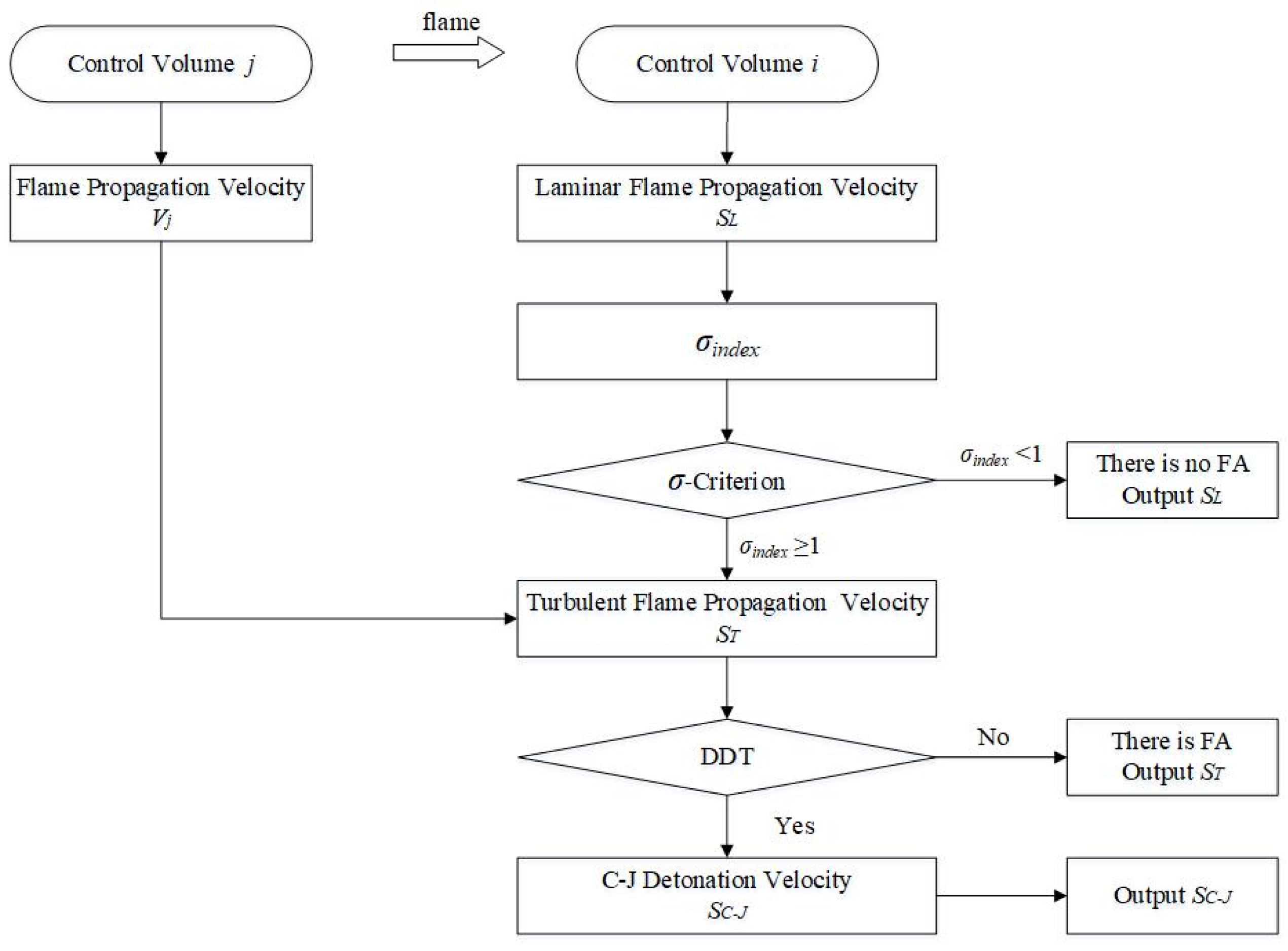
The hydrogen combustion flame acceleration model developed in this paper integrates both laminar and turbulent flame propagation calculation modules, ensuring appropriate response mechanisms for different combustion states while maintaining computational efficiency, as shown in Figure 1.
Figure 1.
Computational framework of the flame acceleration model.
The brief computational framework proceeds as follows:
- Firstly, the laminar flame propagation velocity is derived from Liu-MacFarlane according to the temperature, pressure, and composition of the gas mixtures, establishing fundamental combustion characteristics.
- Secondly, the σindex is calculated as the ratio of the actual expansion ratio to the critical expansion ratio according to the temperature and composition of gas mixtures in the compartment. The σ-criterion is applied to assess whether there is flame acceleration. If σindex < 1, it indicates that there is no flame acceleration, meaning that the gas mixture remains quasi-laminar combustion, and the model will output the laminar flame propagation velocity. Conversely, if σindex ≥ 1, there exists a potential for flame acceleration, and the model will persist in calculating turbulent combustion.
- Then, the turbulent flame propagation velocity is determined by Peters based on the laminar flame propagation velocity and turbulent pulsation, including internal turbulent pulsations generated by intrinsic flame instabilities, external turbulent pulsations induced by gas mixture flow, and obstacles.
- Finally, the local Mach number can be derived from the turbulent flame propagation velocity, which will be compared against the critical Mach number. Both the Mach number criterion (Ma > Mac) and the 7λ criterion will be applied to assess the DDT risk. If DDT is not triggered, the gas mixture remains in a state of turbulent combustion. Under such conditions, the model will calculate and output the turbulent flame propagation velocity, indicating that there is no detonation risk, while flame acceleration phenomena may be observed. Conversely, if the criteria are satisfied, it signifies successful DDT associated with potential transition to detonation. In this case, the model will automatically trigger safety alerts and initiate detonation computation protocols.
4. Model Validation
4.1. RUT Test
In this study, the RUT test is selected for model validation [29], as illustrated in Figure 2. The RUT test is constructed from concrete and positions an electric spark igniter at the left terminus of the channel, which is also the starting point of the flame. The primary combustion channel extends 34.0 m in length with uniform rectangular cross-sectional dimensions of 2.2 m (height) × 2.5 m (width), uniformly instructed with twelve obstacles to create disturbances during the flame propagation. Various heights of concrete obstacles can simulate turbulent disturbances under different blockage ratio conditions. For this study, a blockage ratio of 0.3 was specifically chosen. At the end of the channel, an extended compartment measuring 10.5 m in length with a cross-section of 6.0 m (height) × 2.5 m (width) was connected, designed to simulate hydrogen combustion within large space compartments. This integrated design enables systematic examination for multi-regime combustion characterization under controlled confinement conditions, particularly focusing on flame acceleration and detonation, both in obstacle-laden channels and large-scale combustion instabilities.
Figure 2.
Illustration of RUT test.
The long channel is divided into thirteen uniform control volumes (R1-R13) following obstacles distribution, each with a cross-sectional area of 2.2 m × 2.5 m and a length of approximately 34.0/13 ≈ 2.62 m, resulting in a volume of 14.4 m3 per control volume. The systematic division ensures direct correspondence between obstacle positions and control volume boundaries, enabling precise quantification of turbulence-flame coupling effects. The large space compartment is evenly divided into two expanded control volumes (R14–R15) along the flame transmission direction for capturing pressure transients in unobstructed combustion regimes. Each control volume has a length of 10.5/2 = 5.25 m and an enlarged cross-sectional area of 6.0 m × 2.5 m, yielding a volume of 78.75 m3 per control volume. The critical interface between R13 and R14 is explicitly modeled as a sudden geometric transition zone, maintaining continuity through a blockage ratio of zero (BR = 0).
To validate the accuracy and effectiveness of the hydrogen combustion flame acceleration model developed in this study, a systematic verification is implemented through comparison with the experimental data from Dorofeev et al. [29], who have conducted extensive tests on deflagration and detonation phenomena in the RUT test. The sth7 test, which represents a characteristic deflagration state of hydrogen combustion, is specifically selected, as presented in Table 1.

Table 1.
Test data of sth7 in RUT.
4.2. Results and Analysis
The study initially focuses on verifying the reliability of the laminar flame propagation calculation module, which serves as a critical determinant for characterizing subsequent flame propagation dynamics, and the accuracy of its computational precision fundamentally underpins the overall reliability of the combustion model. Comprehensive validation is conducted, encompassing flame propagation velocity and dynamic pressure during the combustion process. Furthermore, the computational model permits detailed analysis of temperature distribution characteristics throughout flame propagation.
The validation approach not only confirms the model’s capability to capture essential combustion physics but also demonstrates its predictive accuracy in reproducing both temporal evolution and spatial distribution features observed in experiments. The comparison between numerical predictions and experimental measurements supports the model’s competence in simulating hydrogen deflagration dynamics, providing valuable insights into transient thermal phenomena during confined combustion processes.
4.2.1. Laminar Flame Propagation Velocity
A quantitative comparison is conducted between numerical and experimental results of laminar flame velocities from independent studies to systematically evaluate the credibility of the proposed hydrogen combustion flame acceleration framework [30,31], as summarized in Table 2. The results demonstrate that the model achieves high fidelity under lean combustion conditions, with minimal discrepancies observed in laminar flow flame velocity. However, it increases under rich combustion conditions, potentially attributable to enhanced sensitivity to turbulence-chemistry interactions in high-concentration hydrogen combustion. Given that hydrogen concentration in the containment typically remains at a low level under severe accidents, the model demonstrates satisfactory reliability for its intended hydrogen safety analysis applications.
Table 2.
Validation of laminar flame velocity.
4.2.2. C–J Pressure
The algorithm’s capability to predict Chapman–Jouguet (C–J) detonation velocities is rigorously validated through comparative analysis with the experimental data under different hydrogen concentration conditions [32], as presented in Table 3. The results show a good agreement with experiments, with maximum relative errors constrained within 9.96%. This deviation primarily stems from the idealized assumption that the gas mixture is uniformly distributed in the model, which contrasts with the inherent non-uniformity observed in actual experiments. Considering the complexities of flame propagation and experimental uncertainties, the error margins remain within acceptable thresholds for engineering-scale simulations, confirming the model’s good reliability.
Table 3.
Validation of C–J Pressure.
4.2.3. Flame Propagation Velocity
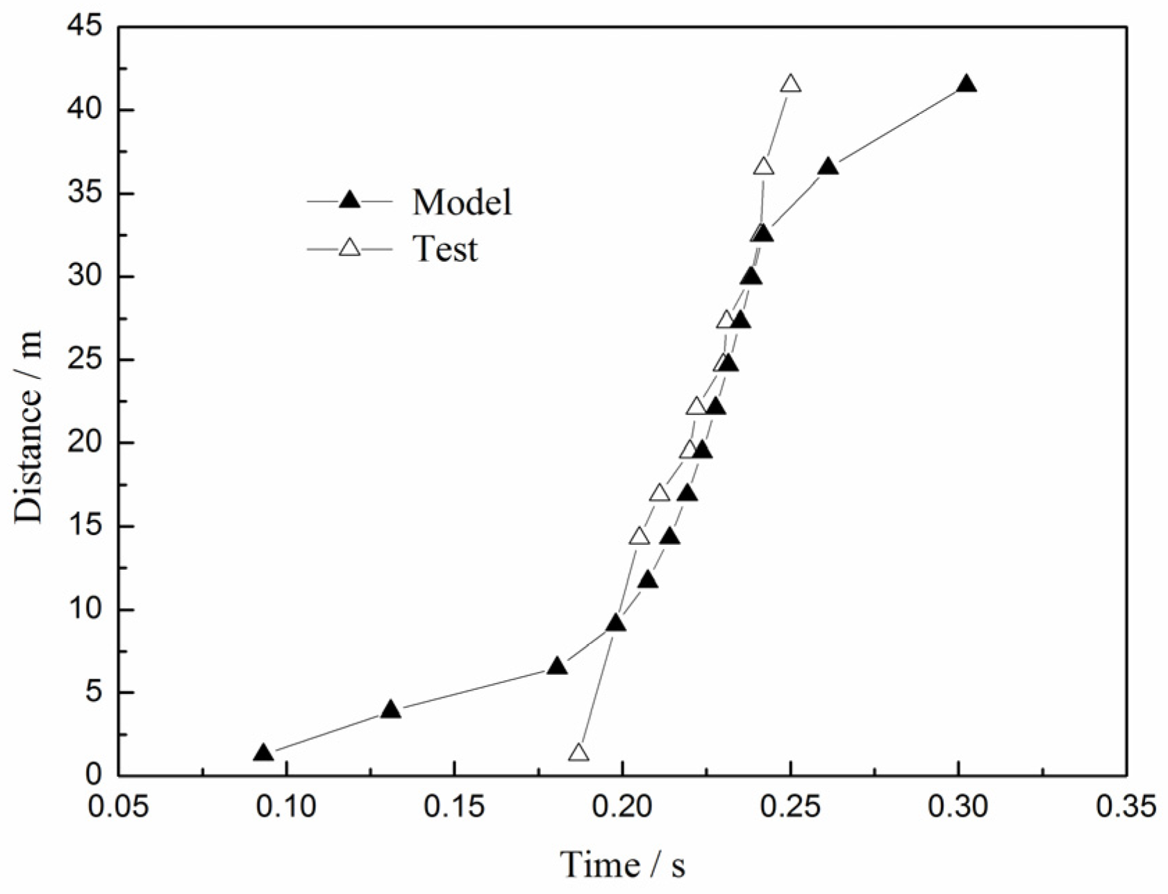
The comparison of the flame front position along the flow-wise direction within the channel is shown in Figure 3. Comparative analysis of flame front positions enables assessment of the model’s accuracy in simulating the flame development and propagation processes, it can be seen clearly that the time gradient variation obtained by the model corresponds well with the test data after the flame is completely developed. The results confirm that the model accurately predicts the flame transmission position within the channel, validating the proficiency of the computational framework in determining flame propagation velocities.
Figure 3.
Comparison of flame front position along the flow-wise direction within the channel.
Especially, noticeable deviations are observed between computational and experimental results in flame front arrival time measurement at initial positions, it is primarily stemming from multiple instability sources: (1) inherent uncertainty in spark-to-flame ignition delays in actual engineering, (2) perturbations in initial ignition energy deposition, and (3) experimental challenges in precisely tracking flame surface evolution. These factors collectively induce pronounced instability in both the initial flame velocity and the flame propagation process. However, the relative error rapidly diminishes and remains within 4.24% as shown in Table 4, demonstrating model robustness under developed combustion conditions at R4–R13.
Table 4.
Validation of flame front position.
Furthermore, the comparative analysis identifies an underestimation of flame front velocities advancing along the channel in numerical simulations when the flame enters the compartment at R14–R15. It principally originates from the flow restructuring effects accompanying abrupt cross-sectional area expansion. The flame front monitored in the RUT test is conducted solely along the horizontal flow-wise direction, neglecting the longitudinal velocity distribution deviation caused by compartment height variations, thereby failing to provide an accurate average flame propagation velocity within the compartment.
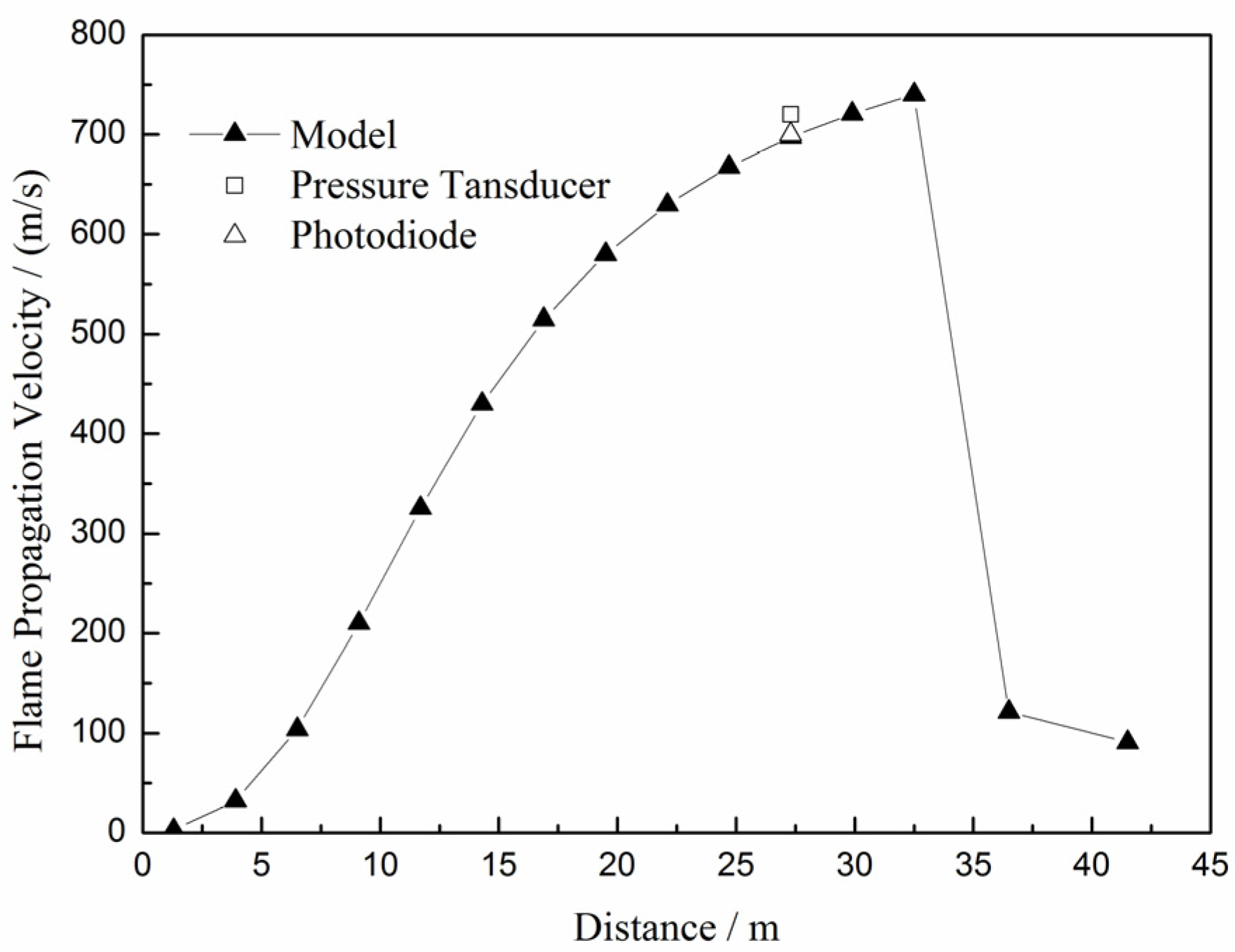
The variation of flame propagation velocity along the channel is shown in Figure 4, revealing distinct acceleration-deceleration dynamics governed by geometric constraints. It can be seen clearly that the flame front continuously accelerates within the channel, culminating in a maximum velocity of 740 m/s at the channel exit (about 32.5 m, R13), where the flame is just about to enter the compartment. However, flame propagation velocity abruptly turns to rapid deceleration due to effects induced by multidimensional flow and pressure expansion, attributed to the sudden cross-sectional expansion of the combustion space.
Figure 4.
Variation of flame propagation velocity along the channel.
The flame front velocities of the RUT test at 27.3 m, derived from pressure transducers and photoelectric sensors, are reported as 720 m/s and 700 m/s, respectively. Therefore, this study selects a center position within control volume R11 at approximately 27.3 m to enable direct comparison, where the flame front velocity predicted by the model is about 697.15 m/s. Finally, the errors are found to be only 0.41% and 3.17% relative to pressure transducers and photoelectric sensors, respectively, as shown in Table 5. The minor deviations demonstrate strong agreement between the model and test, confirming the model’s capability in both flame flow dynamics calculation and combustion-driven acceleration mechanisms simulation.
Table 5.
Validation of flame propagation velocity.
4.2.4. Dynamic Pressure Load
The pressure characteristics within containment combustion exhibit distinct behaviors depending on different flame propagation. In general, there is a gradual increase in gas pressure owing to their relatively slower combustion rates during the conventional combustion processes, including laminar flames and low-intensity turbulent combustion. However, the flame front will generate precursor shock waves and subsequently create a pressure discontinuity surface with an instantaneous significant rise in pressure when the flame velocity approaches sonic velocity in unburned gas.
The variation in dynamic pressure load along the channel during the flame propagation process is shown in Figure 5. The results demonstrate that the computational results are close to the experimental data, yielding a maximum pressure of 14.73 atm simulated by the model. However, the peak pressure measurement in the RUT test remains absent. Experimental data reveal an abrupt pressure increase from 1.198 atm at 15.7 m to 8.205 atm at 22.66 m, while computational results indicate a comparable escalation from 2.16 atm at 16.9 m to 10.35 atm at 24.7 m, as shown in Table 6. The correspondence in both spatial position and pressure elevation can demonstrate the model’s capability in capturing the position of pressure discontinuity, verifying its capacity to accurately simulate the dynamic pressure load during the flame propagation process, which is critical for assessments of containment integrity.

Figure 5.
Variation of flame dynamic pressure along the channel.
Table 6.
Validation of flame dynamic pressure.
4.2.5. Temperature Distribution
The distribution of peak flame temperatures within the channel is illustrated in Figure 6, revealing distinct thermodynamic parameters governed by flame propagation and interactions. The temperature rises instantaneously to an equilibrium temperature of 1961 K when the gas mixture reaches R2. It remains stable thereafter until the flame front approaches the R10, where the combustion temperature has a transient increase to 1993 K. This slight increase correlates directly with the precursor shock wave, as flame velocity approaches the sonic velocity of unburned gas, triggering instantaneous enhancement on pressure loads. Ultimately, the subsequent temperature decreases back to 1961 K due to the diminution or disappearance of the precursor shock wave alongside a reduction in flame propagation velocity when the gas mixture enters the compartment.
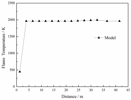
Figure 6.
Distribution of flame temperature along the channel.
The results indicate that the gas mixture attains complete combustion when it enters the second control volume, with subsequent temperatures remaining unchanged. The combustion temperature is only dependent on the initial component and thermodynamic state of the gas mixture. Therefore, it is crucial to focus on instantaneous pressure changes caused by hydrogen combustion, which pose more significant threats in nuclear power plants.
5. Conclusions
This study presents a predictive methodology for flame acceleration under severe accident conditions in nuclear power plants, based on the investigation into the flame acceleration mechanism and its evaluation criteria. The developed hydrogen combustion flame acceleration model is comprehensively validated against the RUT test, demonstrating a strong agreement between the computational results and the experimental data. The primary findings are summarized as follows:
- The flame propagation can be accelerated to near-sonic velocities under appropriate conditions within an obstructed large-scale enclosure, significantly elevating the DDT risks. The proposed model demonstrates high fidelity in predicting flame front position, with a maximum deviation of 3.17% between computational and experimental flame propagation velocities.
- The dynamic pressure will continuously escalate with the increasing flame propagation velocities, forming a pressure discontinuity surface at near-sonic conditions where pressure experiences an instantaneous rise. The model accurately captures peak dynamic pressures during flame propagation, showing close alignment between experimental measurements and computational curves. Additionally, the predicted pressure discontinuity surface is consistent with that from the test.
- The flame temperature is exclusively governed by the initial component and thermodynamic state when the gas mixture is completely combusted, and it will maintain a quasi-constant maximum value. Therefore, we should pay more attention to the dynamic pressure for hydrogen risk assessments in nuclear power, which may cause greater threats than thermal effects.
- The hydrogen combustion flame acceleration model developed in this study enables high-precision simulations of flame propagation across both laminar and turbulent combustion within multiple control volume systems. The model can also be integrated into a severe accident analysis program, featuring the comprehensive model framework and enhanced computational accuracy. This advancement allows for rigorous hydrogen combustion risk assessment in containment during severe accidents, providing critical technical support for severe accident assessment, mitigation, and investigation in nuclear power plants.
Author Contributions
Conceptualization, R.L., J.Y., R.M. and Y.Y.; Data curation, R.L. and Y.L.; Investigation, Y.L., R.M. and Y.Y.; Methodology, R.L., J.Y. and X.Y.; Resources, X.Y., Y.L., R.M. and Y.Y.; Software, J.Y. and X.Y.; Validation, R.L., J.Y. and Y.L.; Writing—original draft, R.L.; Writing—review and editing, X.Y., R.M. and Y.Y. All authors have read and agreed to the published version of the manuscript.
Funding
This research received no external funding.
Data Availability Statement
The original contributions presented in this study are included in the article. Further inquiries can be directed to the corresponding authors.
Conflicts of Interest
Authors Ran Liu, Jingyi Yu, Xiaoming Yang, Rubing Ma, and Yidan Yuan were employed by the company China Nuclear Power Engineering Co., Ltd. The remaining authors declare that the research was conducted in the absence of any commercial or financial relationships that could be construed as a potential conflict of interest.
References
- Sehgal, B.R. Nuclear Safety in Light Water Reactors: Severe Accident Phenomenology; Academic Press: Cambridge, MA, USA, 2012. [Google Scholar]
- Liang, Z.; Sonnenkalb, M.; Bentaib, A. Status Report on Hydrogen Management and Related Computer Codes. Nuclear Safety NEA/CSNI/R(2014)8. 2014. Available online: https://inis.iaea.org/search/search.aspx?orig_q=RN:45089843 (accessed on 26 June 2014).
- Kumar, R.K.; Koroll, G.W.; Heitsch, M. Carbon Monoxide-Hydrogen Combustion Characteristics in Severe Accident Containment Conditions. NEA/CSNI/R(2000)10. 2000. Available online: https://inis.iaea.org/records/m4nhg-50d03 (accessed on 11 March 2000).
- Breitung, W.; Chan, C.; Dorofeev, S. Flame Acceleration and Deflagration-to-Detonation Transition in Nuclear Safety. Nuclear Safety NEA/CSNI/R(2000)7. 2000. Available online: https://www.oecd-nea.org/jcms/pl_17424/flame-acceleration-and-deflagration-to-detonation-transition-in-nuclear-safety?details=true (accessed on 30 August 2000).
- Yu, J.Y.; Yang, X.M.; Yang, Y. Research on Hydrogen Combustion Model in Severe Accident. Mod. Inf. Technol. 2023, 7, 149–153. [Google Scholar]
- Markstein, G.H. Chapter B Theory of Flame Propagation. In AGARDograph; Elsevier: Amsterdam, The Netherlands, 1964; Volume 75, pp. 5–14. [Google Scholar]
- Markstein, G.H. Experimental and theoretical studies of flame front stability. J. Aeronaut. Sci. 1951, 18, 199–209. [Google Scholar] [CrossRef]
- Matalon, M.; Matkowsky, B.J. Flames as gas dynamic discontinuities. J. Fluid Mech. 1982, 124, 239–259. [Google Scholar] [CrossRef]
- Sivashinsky, G.I. Instabilities, Pattern Formation, and Turbulence in Flames. Annu. Rev. Fluid Mech. 1983, 15, 179–199. [Google Scholar] [CrossRef]
- Teodorczyk, A.; Lee, J.H.; Knystautas, R. Propagation mechanism of quasi-detonations. Symp. Combust. 1989, 22, 1723–1731. [Google Scholar] [CrossRef]
- Bychkov, V.; Petchenko, A.; Akkerman, V. Theory and modeling of accelerating flames in tubes. Phys. Rev. E Stat. Nonlinear Soft Matter Phys. 2005, 72, 046307. [Google Scholar] [CrossRef]
- Bychkov, V.; Akkerman, V.; Fru, G. Flame acceleration in the early stages of burning in tubes. Combust. Flame 2007, 150, 263–276. [Google Scholar] [CrossRef]
- Johansen, C.T.; Ciccarelli, G. Visualization of the unburned gas flow field ahead of an accelerating flame in an obstructed square channel. Combust. Flame 2009, 156, 405–416. [Google Scholar] [CrossRef]
- Ciccarelli, G.; Johansen, C.T.; Parravani, M. The role of shock–flame interactions on flame acceleration in an obstacle laden channel. Combust. Flame 2010, 157, 2125–2136. [Google Scholar] [CrossRef]
- Oh, K.H.; Kim, H.; Kim, J.B. A study on the obstacle-induced variation of the gas explosion characteristics. J. Loss Prev. Process Ind. 2001, 14, 597–602. [Google Scholar] [CrossRef]
- Veser, A.; Breitung, W.; Dorofeev, S.B. Run-up distances to supersonic flames in obstacle-laden tubes. J. De Phys. IV 2002, 12, 333–340. [Google Scholar] [CrossRef]
- Lin, Z.Y. The Detonation Phenomenon; National Defense Industry Press: Beijing, China, 2013. [Google Scholar]
- Francis, A.M.; Benjamin, V.; Omar, D. Numerical study of the flame acceleration mechanisms of a lean hydrogen/air deflagration in an obstructed channel. Int. J. Hydrogen Energy 2024, 89, 224–232. [Google Scholar]
- Yao, Q.; Li, S.Q.; Wang, Y. An Introduction to Combustion Concepts and Applications; Tsinghua University Press: Beijing, China, 2011. [Google Scholar]
- Smooke, M.D. Solution of Burner-Stabilized Premixed Laminar Flames by Boundary Value Methods. J. Comput. Phys. 1982, 48, 72–105. [Google Scholar] [CrossRef]
- James, F.D. Turbulent premixed combustion: Flamelet structure and its effect on turbulent burning velocities. Prog. Energy Combust. Sci. 2008, 34, 91–134. [Google Scholar]
- Bradley, D. How Fast Can We Burn. In Proceedings of the Twenty-Fourth Symposium (International) on Combustion, Sydney, Australia, 5–10 July 1992; pp. 247–262. [Google Scholar]
- Liu, D.D.; MacFarlane, R. Laminar burning velocities of Hydrogen-Air-Steam Flames. Combust. Flame 1983, 49, 59–71. [Google Scholar] [CrossRef]
- Bruls, H.K.; Lefebvre, M.H.; Berghmans, J. On Deviations from Ideal Chapman-Jouguet Detonation Velocity. In Proceedings of the Twenty-Fifth Symposium (International) on Combustion, California, CA, USA, 31 July–5 August 1994; pp. 37–44. [Google Scholar]
- Saif, M.; Wang, W.T.; Pekalski, A. Chapman–Jouguet deflagrations and their transition to detonation. Proc. Combust. Inst. 2016, 36, 2771–2779. [Google Scholar] [CrossRef]
- Dorofeev, S.B.; Kuznetsov, M.S.; Alekseev, V.I. Evaluation of limits for effective flame acceleration in hydrogen mixtures. J. Loss Prev. Process Ind. 2001, 14, 583–589. [Google Scholar] [CrossRef]
- Kuznetsov, M.; Redlinger, R.; Breitung, W. Laminar Burning Velocities of hydrogen -oxygen -steam mixtures at elevated temperatures and pressures. Proc. Combust. Inst. 2011, 33, 895–903. [Google Scholar] [CrossRef]
- Hong, S.W.; Kim, S.B.; Kim, H.D. Three-dimensional behaviors of the hydrogen and steam in the APR1400 containment during a hypothetical loss of feed water accident. Ann. Nucl. Energy 2007, 34, 992–1001. [Google Scholar]
- Dorofeev, S.B.; Sidorov, V.P.; Kuznetsov, M.S. Effect of scale on the onset of detonations. Shock. Waves 2000, 10, 137–149. [Google Scholar] [CrossRef]
- Davis, S.G.; Joshi, A.V.; Wang, H. An optimized kinetic model of H2/CO combustion. Proc. Combust. Inst. 2005, 30, 1283–1292. [Google Scholar] [CrossRef]
- Bradley, D.; Lawes, M.; Liu, K.X. Laminar burning velocities of lean hydrogen–air mixtures at pressures up to 1.0 MPa. Combust. Flame 2007, 149, 162–172. [Google Scholar] [CrossRef]
- Dorofeev, S.B.; Sidorv, V.P.; Dvoinishnikov, A.E. Deflagration to Detonation Transition in Large Confined Volume of Lean Hydrogen-Air Mixtures. Combust. Flame 1996, 104, 95–110. [Google Scholar] [CrossRef]

Disclaimer/Publisher’s Note: The statements, opinions and data contained in all publications are solely those of the individual author(s) and contributor(s) and not of MDPI and/or the editor(s). MDPI and/or the editor(s) disclaim responsibility for any injury to people or property resulting from any ideas, methods, instructions or products referred to in the content. |
© 2025 by the authors. Licensee MDPI, Basel, Switzerland. This article is an open access article distributed under the terms and conditions of the Creative Commons Attribution (CC BY) license (https://creativecommons.org/licenses/by/4.0/).