Article

Adaptive Line Resistance Estimation and Compensation for Accurate Power Sharing of Droop-Controlled DC Microgrids

1
College of Electrical, Energy and Power Engineering, Yangzhou University, Yangzhou 225127, China
2
Wolfson School, Loughborough University, Loughborough LE11 3TU, UK
3
College of Intelligent Manufacturing, Yangzhou Polytechnic Institute; Yangzhou 225127, China
4
Frazer-Nash Consultancy; Leatherhead KT22 7LH, UK
*
Author to whom correspondence should be addressed.
Energies 2025, 18(9), 2183; https://doi.org/10.3390/en18092183
Submission received: 1 April 2025 / Revised: 22 April 2025 / Accepted: 23 April 2025 / Published: 24 April 2025

Abstract

:
For a DC microgrid with a traditional droop control strategy, achieving accurate power sharing among power converters is challenging due to mismatched line resistance. In a multi-bus DC microgrid system, changes in the power flow can further lead to variation in the equivalent line resistance of each power converter. To improve power sharing accuracy, an adaptive line resistance estimation method is proposed in this paper, which can accurately estimate line resistance without additional hardware. The estimated line resistances are then used to compensate the droop coefficient of each power converter to ensure accurate power sharing between power converters. Simulation and experimental results are presented to demonstrate the effectiveness of the proposed method for single bus, multi-bus, and ring-bus DC microgrid systems.

1. Introduction

In recent years, direct current (DC) microgrids have emerged as one of the promising solutions to efficiently integrate growing distributed renewable energies [1], which have advantages of high efficiency, enhanced flexibility, and simplified control mechanisms [2].
Hierarchical control strategies [3,4] are commonly employed in DC microgrid control, consisting of three control layers [5]: the primary, secondary, and tertiary control layers. Droop control is commonly applied in the primary control layer [6]. In droop control, droop coefficients are introduced as virtual output resistances of power converters to reduce the circulating current between parallel-connected power converters [4] and achieve power sharing between power converters within a DC microgrid [7,8]. However, the existence of transmission line resistance on the output side of the converters in parallel could result in bad impacts on the traditional droop control method in terms of power sharing [9]. Many methods have been proposed to solve this challenge.
Adaptive droop coefficient tuning based on load conditions is reported on in [10,11,12] to enhance the power sharing performance of traditional droop control. Adaptive droop control has better flexibility and can achieve more accurate power sharing in DC microgrids. However, the power sharing accuracy is still limited and can be affected by the mismatched line resistance. A nonlinear droop control strategy was proposed in [13]; the droop coefficients are adaptive according to the variation of local output current and voltage. However, it may cause stability issues because of the introduced nonlinear factors.
Low-bandwidth communication (LBC)-based solutions [14,15,16,17,18,19,20,21,22,23,24] have been proposed to address the power sharing issue of droop control. In these solutions, LBC is used to provide additional inputs to the primary controller of each power converter. In [14], the slide mode control (SMC) is employed to correct the power sharing between parallel converters based on the common DC bus voltage information transferred by the LBC. In [16], the DC bus voltage value is sent to all power converters via LBC, and then the line resistance is estimated for compensation. In [15], the information of neighbor converters is shared among them, and compensation terms are generated for each converter to ensure the power sharing performance. In [17], the output voltage and current value of each power converter are sent to other power converters via LBC to implement power sharing. In methods proposed in [18,19,20], the power sharing algorithm is implemented in the secondary control layer through average current control. In [21,22], a communication network is designed for a multi-bus DC microgrid to enable the power converter to share its control variables with its neighbors, and then a global consensus-based cooperative control is designed for power sharing. A supervisory control scheme is proposed in [23] for power management in a multi-bus DC microgrid. The power reference for each power converter is calculated in the central controller and then transmitted to the power converter via LBC to adjust the droop coefficient. However, these methods [16,17,18,19,20,21,22,23,24] rely on LBC, which increases the system cost and complexity, reduces system reliability, and is not suitable for many low-cost DC microgrid applications without communication links.
Several communication-less methods have been proposed to improve the power sharing accuracy by line resistance estimation and compensation [8,9,25,26,27,28]. A line resistance estimation method based on single pulse injection was proposed in [9,28]. However, it is an open-loop based estimation, and the estimation accuracy is limited. In [8], small AC voltages are injected to the DC bus to estimate the line resistance. The injected AC voltages are under a frequency-droop control method to indicate the output current of each converter. However, complex control algorithms are required to deal with the AC reactive power and frequency control [25]. An algorithm based on the closed-loop calculation to estimate the line resistance was proposed in [26]. Perturbations are introduced to the voltage loop reference value. By measuring the fluctuations of voltage and current, the line resistance is estimated by a closed-loop PI controller. The bandwidth of the voltage control loop is usually low, and introducing perturbations directly to the output voltage reference will cause fluctuation in the DC bus voltage. However, the DC bus voltage fluctuation is assumed negligible in the resistance estimation, which reduces the estimation accuracy. In [27], within a switching period, the output voltage v o and current i o are sampled three times, then the cable line impedance can be calculated. However, the voltage fluctuation on the DC bus is still not considered, which can bring errors to the estimation.
For single-bus DC microgrids, line resistance varies due to different conductor temperature caused by different power flow and external environmental temperatures [29]. For multi-bus DC microgrids, the equivalent line resistance between the converters and virtual common DC bus can be changed with power flow fluctuations caused by load or generation variations. However, this line resistance variation during the microgrid operation was not considered in the existing DC microgrid line resistance estimation methods. This research gap is addressed in this paper.
This paper proposes a novel approach to improve power sharing accuracy among Boost converters in DC microgrids by a closed-loop line resistance estimation. The method requires no communication link, and is applicable to both single-bus and multi-bus DC microgrids. The main contributions of the paper are as follows:
(1)
A new method is proposed for estimating line resistance by injecting small disturbance signals into the current loop of the Boost converter controller. The method is decentralized in manner and simple to implement.
(2)
The variation of DC bus voltage during the line resistance estimation period is considered by employing a Kalman filter (KF) to estimate DC bus voltage fluctuations, which enhances the line resistance estimation accuracy.
(3)
The line resistance variation during the DC microgrid operation is addressed in this study. For multi-bus systems, by employing the Y- Δ transform, a multi-bus DC microgrid system can be effectively converted into an equivalent single-bus system. The line resistance is estimated regularly to reduce the power sharing inaccuracy caused by power flow variation and line conductor temperature changes.
(4)
The proposed scheme adopts a fully localized control strategy, eliminating the requirement of additional communication links for accurate power sharing. This simplifies the system structure, enhances reliability, and reduces costs.
This paper is organized as follows: the proposed line resistance estimation and compensation algorithm is explained in Section 2, the equivalence of multi-bus systems and ring-bus systems is described in Section 3, and the implementation and experimental results are presented in Section 4. Finally, the conclusions are drawn in Section 5. Additionally, the system stability analysis is attached in Appendix A.

2. The Proposed Line Resistance Estimation Algorithm

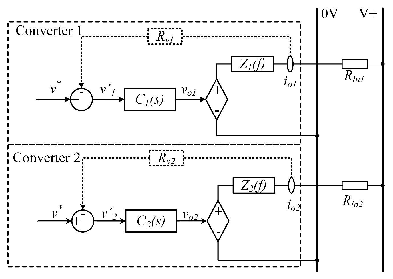
2.1. Problem Formulation

For a DC microgrid with droop control, the output voltage reference of the k th power converter v k can be described as follows:
v k = v k * i o k · R v k , k 1 , 2 , 3 , . . , n
where v k * is the floating voltage, R v k is the virtual resistance (droop coefficient), i o k is the output current of the k th converter, and n is the number of converters in a DC microgrid.
A diagram of droop control for a DC system with two parallel connected converters is shown in Figure 1, where C k ( s ) is the kth converter’s transfer function from the output voltage reference v k to the output voltage v o k , and Z k ( f ) is the output impedance of the k th converter.
Assume the line resistances between the converters and common DC bus, R l n 1 and R l n 2 , are zero, the power sharing between two converters is tightly regulated according to the droop coefficient ratio:
ρ = P o 1 P o 2 = i o 1 i o 2 = R v 2 R v 1
where ρ is the power sharing ratio, and P o k is the output power of the k th converter.
Practically, when considering the line resistances, the power sharing ratio of two converters is as follows:
ρ = i o 1 i o 2 = R v 2 + R l n 2 R v 1 + R l n 1
For traditional droop control [30], power sharing accuracy is susceptible to line resistance, which leads to there being a trade-off between DC bus voltage regulation and power sharing accuracy in setting the droop coefficients [31,32,33,34,35,36,37,38,39], as shown in (3).

2.2. The Proposed Line Resistance Estimation Method

The synchronuous Boost converter, which is considered a good candidate in this study, is widely used in renewable energy harvesting and energy storage buffering. The block diagrams of the proposed line resistance estimation method are shown in Figure 2 and Figure 3. It includes introducing perturbations to the current loop (Figure 2) and estimating the line resistance through a closed-loop PI controller and a KF (Figure 3).
For the k th Boost converter, as shown in Figure 2, small perturbations i ˜ L are added to the voltage loop output i * and form the reference for the current loop. The injected perturbations will cause a small variation in the output current ( Δ i o k ) and voltage ( Δ v o k ) of the converter, which will be used for line resistance estimation.
The injected current perturbation is a set of high-frequency pulse wave signals. The parameters of the injected perturbations are selected as follows in this research: f p e r t = 0.5 f c u t i , f c u t i = 0.1 f s w , and A p e r = 0.01 i L , where f p e r t is the frequency of the injected perturbation, f c u t i is the bandwidth of the current loop, f s w = 25 kHz is the switching frequency, A p e r is the amplitude of the injected perturbation, and i L is the input current (inductor current) of the power converter. The selection of the perturbation parameters is flexible for different systems, but must ensure the system stability and produce measurable voltage/current variations.
Ignoring the line inductance, the DC bus voltage v b u s can be calculated from the k th power converter output current i o k and output voltage v o k as
v b u s = v o k R l n k · i o k
where R l n k is the line resistance between the converter and the DC bus.
For a DC microgrid within a relatively small area, the transmission line resistance usually significantly outweighs the line self-inductance [40]. If the transmission line cables are parallel conductors with short distances, the line inductance will be much smaller than its resistance. Therefore, it is reasonable to ignore the influence of line inductance.
From (4), the DC bus voltage fluctuation Δ v b u s during the perturbation can be described as follows:
Δ v b u s = Δ v o k R l n k · Δ i o k
Rearrange (5), and the following equation can be obtained:
Δ v o k R l n k · Δ i o k Δ v b u s = 0
Based on (6), a closed-loop line resistance estimation with consideration of the DC bus voltage fluctuation is implemented, as shown in Figure 3. The input of the PI controller is
Δ v o k R l n k , e s t · Δ i o k Δ v b u s
where R l n k , e s t is the estimated line resistance between the k th converter and the DC bus.
As shown in Figure 3, a PI estimator is used as the line resistance estimation error amplifier. Its output is the estimated line resistance, which is fed back into the (7). Once the PI estimator achieves stability, its input is zero, indicating that the estimated line resistance closely matches the actual line resistance value. The estimated line resistance will be compensated in the droop control to improve the power sharing accuracy, and also will be used to calculate the variation in the DC bus voltage through the following:
Δ v b u s , c a l = Δ v o k R l n k , e s t · Δ i o k
and a KF to further improve the line resistance estimation accuracy. The output of the KF is the estimated DC bus voltage fluctuation Δ v b u s , r e p , which is fedback to the input of the PI controller as shown in Figure 3.

2.3. Design of the Kalman Filter

To improve the line resistance estimation accuracy, a KF is introduced to estimate the representative value of the DC bus voltage fluctuation Δ v b u s , r e p .
A low-pass filter is not suitable for this application. For a low-pass filter, the amplitudes of all high-frequency components of input signals are attenuated. Therefore, the output of the low-pass filter is predominately governed by low-frequency components of the input signal, which facilitates convergence but fails to accurately represent the expected value of the actual input signal. Compared to low-pass filters, KF can handle the entire historical time series of signals through iterative algorithms. Therefore, the output of the KF achieves both convergence and accuracy relative to the actual signal’s expected value.

2.3.1. Predict

The KF state prediction equation is
x ^ k k 1 = F k · x ^ k 1 k 1 + B k · u k
where x ^ k k 1 is an a priori state estimate; x ^ k 1 k 1 is an a posteriori state estimate; F k is the state transition model applied to the previous state x k 1 ; and u k is the control vector, representing the controlling input into control–input model. B k is the control–input model applied to the control vector u k .
In this application, a one-dimension KF with unity gain is applied, so (9) can be simplified as follows:
x ^ k k 1 = x ^ k 1 k 1
The KF state estimate prediction covariance equation is as follows:
P ^ k k 1 = F k · P ^ k 1 k 1 · F k T + Q k
where P ^ k k 1 is an a priori estimate covariance matrix, and Q k is the covariance of the process noise. For the one-dimension KF without process noise, (11) can be simplified as follows:
P ^ k k 1 = P ^ k 1 k 1

2.3.2. Update

The KF updated state estimation equation is
x ^ k k = ( I K k · H k ) · x ^ k k 1 + K k · z k
where x ^ k k is the updated state estimation; K k is the Kalman gain; H k is the observation model; and z k is the observation at time k. For the one-dimension KF with unity gain, (13) can be simplified as
x ^ k k = x ^ k k 1 + K k · ( z k x ^ k k 1 )
The KF updated estimation covariance equation is as follows:
P k k = ( I K k · H k ) · P ^ k k 1
where P k k is a updated estimation covariance. For the one-dimension KF with unity gain, (15) can be simplified as
P k k = ( 1 K k ) · P ^ k k 1
The equation of the optimal Kalman gain is
K k = P ^ k k 1 · H k T · ( H k · P ^ k k 1 · H k T + N k ) 1
where N k is the covariance of the observation error at time k. For the one-dimension KF with unity gain, (17) can be simplified as
K k = P ^ k k 1 P ^ k k 1 + N k

2.4. Line Resistance Compensation

After the line resistance of the k th power converter is estimated, the effects of mismatched line resistance on power sharing can be compensated in the droop controller, as shown in (19):
v k = v k * i o k · ( R v k R l n k , e s t )
where R v k is the droop coefficient of the k th power converter, and R l n k , e s t is the estimated line resistance. It should be noted that the droop coefficient R v k can be different for different converters in the system.
After compensation, the power sharing accuracy between parallel connected power converters can be improved.

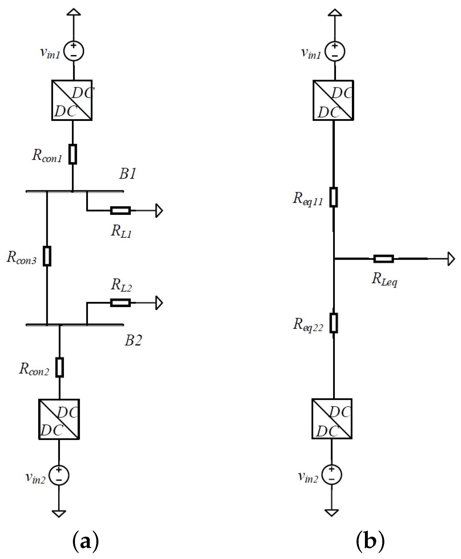
3. Equivalent Line Resistance Estimation for Multi-Bus Systems and Ring-Bus Systems

In general, some multi-bus DC microgrid systems can be transformed into equivalent single-bus DC microgrid systems. Therefore, the same line resistance estimation method can be applied to estimate the equivalent line resistance between the power converter output and the virtual common DC bus for those multi-bus DC microgrids. In this research, two typical multi-bus systems are studied to illustrate the transform process and the effect of power flow change on the equivalent line resistance.

3.1. Two-Bus DC Microgrid System

Figure 4a shows a two-bus DC microgrid system, which has two DC buses ( B 1 and B 2 ), and an energy source converter and an equivalent resistance load are connected to each bus. The line resistance between two DC buses is R c o n 3 .
According to the Y Δ transform, this two-bus system can be transformed to an equivalent single-bus system, as shown in Figure 4b. The values of the two equivalent line resistances are as follows:
R e q 11 = R L 1 · R c o n 3 R c o n 3 + R L 1 + R L 2 + R c o n 1
R e q 22 = R L 2 · R c o n 3 R c o n 3 + R L 1 + R L 2 + R c o n 2

3.2. Ring-Bus System

In this section, a three-bus ring system as shown in Figure 5a is studied. According to the Y Δ transform, this three-bus ring system can be transformed to an equivalent single-bus system, as shown in Figure 5b. The values of the two equivalent line resistances are as follows:
R e q 1 = R 12 · R 13 R 12 + R 13 + R 23 + R a · R c R a + R b + R c + R c o n 1
R e q 2 = R a · R b R a + R b + R c + R c o n 2
where R a = R 12 · R 23 R 12 + R 13 + R 23 , R b = R L 2 , R c = R 13 · R 23 R 12 + R 13 + R 23 + R L 3 .
From (20) to (23), it shows that the equivalent line resistances of multi-bus microgrid systems are load-dependent. If the system includes variable generation sources, such as a photovoltaic (PV) system operating under maximum power point tracking (MPPT), the fluctuations in power generation could be equivalent to load variations, and will have the same impact on equivalent line resistances. Therefore, the line resistance estimation values need to be updated regularly during the microgrid operation. In this research, a simple algorithm is proposed and the equivalent line resistance is estimated every a few seconds for multi-bus DC microgrid applications. Online load (or power flow) variation detection could further improve the effectiveness of the proposed algorithm, and this will be considered in future work dedicated to this research.

4. Experimental Validation

The proposed line resistance estimation and compensation method has been implemented and evaluated in three DC microgrid configurations experimentally:
  • A single bus DC microgrid with three power converters.
  • A two-bus DC microgrid with two power converters.
  • A ring-bus DC microgrid with three DC buses and two power converters.

4.1. Experiment 1: Single-Bus DC Microgrid

The experimental setup for a single-bus DC microgrid with three power converters is shown in Figure 6. The DC microgrid includes three parallel connected identical bi-directional Boost converters, and the loads include a programmable DC electronic load and a resistor load ( R l o a d ). Resistors ( R l n 1 , 2 , 3 ) are used between power converters and the DC bus to represent the line resistance of the transmission line. Notably, it is not necessary to have identical converters for the experiment. The proposed method only requires local information, and is also fully compatible with DC microgrids comprising different converters.
In this experimental study, the output current of each power converter was measured as the current sharing ratio corresponding to the power sharing ratio of power converters when the output voltages of converters were same. The probe used in the experiment was the Textronix A622 AC/DC (Textronix, Beaverton, OR, USA) current probe, and the setting was 100 mV/A.
For the Boost converters used in this experiment, the power rating was 250 W, nominal input voltage 24 V, output voltage 48 V, and the switching frequency 25 kHz. A TI’s TMS320F28335 micro-processor (Texas Instruments, Dallas, TX, USA) was used for power converter control. Each Boost converter also had an Arduino Nano 33 (Arduino, Somerville, MA, USA) IoT board for sending operation data (such as current, voltage, the estimated line resistance, etc.) to a lab-developed microgrid Supervisory Control and Data Acquisition (SCADA) system via WiFi with a data transfer frequency of 1 Hz. It is important to note that the SCADA tool (version 1.0) is only for monitoring and recording the system operation parameters, not for controlling them in this experiment.
The system parameters for this experiment are listed in Table 1. The droop coefficients for the three converters are set to 0.7 Ω , and the line resistances of three converters are set to 0.3 Ω , 0.2 Ω , and 0.1 Ω , respectively.
To avoid large estimation error caused by the perturbation current of other converters, the line resistances of the three converters are not estimated simultaneously. Normally, the minimum waiting period can be set at 8 ms considering the estimation process duration, but in this experiment, the waiting period was intentionally set at 2 s to illustrate the adjusting process of each converter. This delay period approach has been supported by other researchers in their line resistance estimation methods [9,26,28]. As shown in Figure 7, the three converters perform the line resistance estimation and compensation in sequence.
At the beginning of the experiment, the DC electronic load is set as a 4 A constant current load, and the resistor load current is about 0.5 A. From t = 0 s to t = t 1 , three converters are under droop control without line resistance compensation. Due to different line resistances, the output currents of the three converters are 1.39 A, 1.57 A, and 1.65 A, respectively, which aligns with the expected values. The DC bus voltage is 46.79 V.
The proposed line resistance estimation and compensation algorithm starts to run at t = t 1 for the first converter. The i ˜ L perturbation is applied to the current loop; after the convergence of the estimated error, the droop coefficient is updated and the estimation performed. Three converters complete the line resistance estimation and compensation in turn. Between t = t 3 and t = t 4 , the output currents of three converters are 1.52 A, 1.52 A, and 1.51 A, respectively. This shows the line resistances are accurately estimated and compensated in droop control. The DC bus voltage increases from 46.79 V to 47.2 V.
Next, the DC electronic load current is changed from 4 A to 3.5 A at t = t 4 , from 3.5 A to 4.5 A at t = t 5 , from 4.5 A to 3.6 A at t = t 6 , and from 3.6 A to 4 A at t = t 7 , respectively, and the resistor load current is kept at 0.5 A. During this load variation period, the current sharing between these three parallel converters is still about 1:1:1. This shows that only one line resistance estimation is required for single-bus DC microgrids, and the current sharing accuracy remains unaffected by load variations.
The line resistance estimation results are transferred to the SCADA system and recorded, as shown in Figure 7b. The estimated line resistances of these three converters are R l n 1 e s t = 0.30 Ω , R l n 2 e s t = 0.21 Ω and R l n 3 e s t = 0.10 Ω , respectively, which are close to the actual line resistance setting values.
In this experiment, the total load current is kept the same. The scenario of variable load current (including suddenly taking out a converter in the system due to a fault, which is essentially a load current change for the remaining converters) will be verified in experiment results for multi-bus systems.
When considering the line resistance variation due to conductor temperature changes, regular line resistance estimation is also recommended for single-bus systems. However, the time intervals between line resistance estimations should be much longer than those of multi-bus systems.

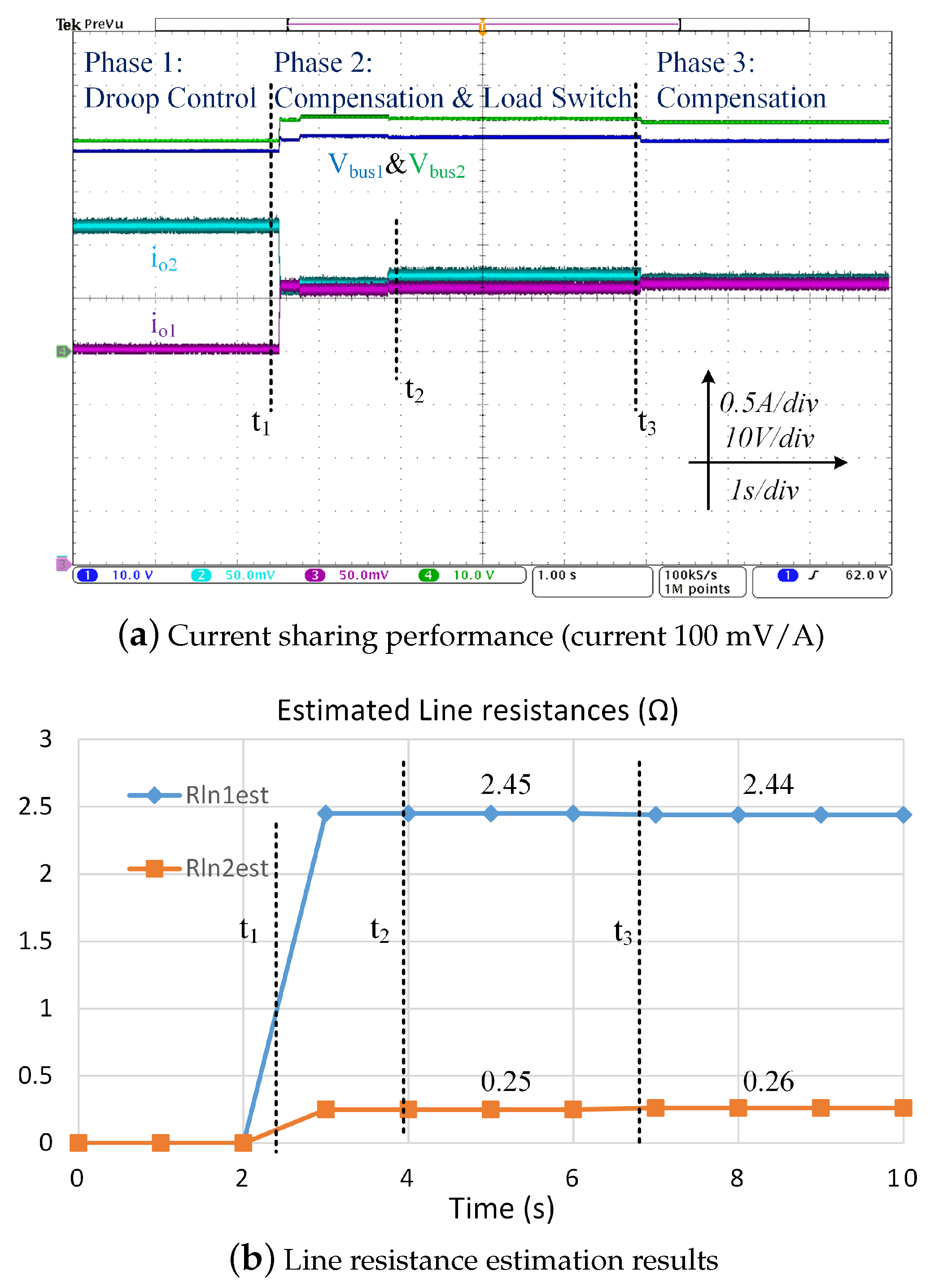
4.2. Experiment 2: Multi-Bus DC Microgrid

The equivalent line resistance estimation and current sharing performance of the proposed method is evaluated in a two-bus DC microgrid experimental setup as shown in Figure 8. The system has two DC buses, and both have a constant current load connected. The experiment parameters are shown in Table 2. The droop coefficients for two converters are set as the same as that used for 2.8 Ω , the line resistances of two converters are set as 2.4 Ω and 0.2 Ω , respectively, and the line resistance between two DC buses is set as 0.1 Ω . The large line resistance setting of 2.4 Ω is to represent a long-distance wire between the converter and the DC bus. A large droop coefficient value was chosen for this experiment to ensure it would be larger than the corresponding line resistance value, and the droop coefficients after compensation as (19) were positive.
The experimental waveforms of current sharing performance are shown in Figure 9a.
At the beginning of the experiment, two constant current loads were set as e l o a d 1 = 2.7 A and e l o a d 2 = 2 A, and the resistor load current was about 0.5 A. Under droop control without line resistance compensation, the output currents of two converters were i o 1 ( 1 ) = 2.08 A and i o 2 ( 1 ) = 3.21 A, respectively. The proposed algorithm started at t = t 1 . After the proposed line resistance estimation and compensation, the current sharing ratio was close to 1:1, and two output currents of two converters were i o 1 ( 2 ) = 2.57 A and i o 2 ( 2 ) = 2.62 A, respectively. This shows the proposed method is effective for this two-bus DC microgrid system.
At t = t 2 , two constant current loads changed to e l o a d 1 = 2.6 A and e l o a d 2 = 2.2 A. According to (20) and (21), the equivalent line resistance changes due to the load variation. Therefore, without new line resistance estimation, two output currents of two converters were changed to i o 1 ( 3 ) = 2.61 A, and i o 2 ( 3 ) = 2.76 A, respectively, and the current sharing performance was reduced. To address this, the proposed algorithm needs to be run regularly. In this experiment, it ran every 4 s. Therefore, the line resistance estimation started again at t = t 3 . After compensation, the current sharing ratio became nearly 1:1 again, and the two output currents of two converters were i o 1 ( 4 ) = 2.65 A and i o 2 ( 4 ) = 2.66 A, respectively.
The line resistance estimation results were transferred to the SCADA system and recorded, as shown in Figure 9b. With the initial load condition, the actual equivalent line resistances of each converter (calculate from (20) and (21)) were R l n 1 e q 1 = 2.439 Ω and R l n 2 e q 1 = 0.259 Ω , and the corresponding estimation results were R l n 1 e s t 1 = 2.45 Ω and R l n 2 e s t 1 = 0.25 Ω , respectively, which are close to the actual line resistance values. After the load change, the actual equivalent line resistances of each converter were R l n 1 e q 2 = 2.448 Ω and R l n 2 e q 2 = 0.255 Ω . The estimated line resistance values for each converter were R l n 1 e s t 2 = 2.44 Ω and R l n 2 e s t 2 = 0.26 Ω .
As shown in Figure 9a, the DC bus increased after compensation at t = t 1 . The reason is that after compensation, the total equivalent coefficient is reduced from ( R v + R l n ) to the designed value of R v , where R v is the droop coefficient, and R l n is the line resistance. So, the DC bus voltage drop caused by the line resistance is compensated, and the DC bus voltage is restored to the designed value under the same load condition.
The above experimental results show that to ensure the current sharing accuracy for multi-bus DC microgrids with load variation operations, the proposed algorithm needs to be executed periodically.

4.3. Experiment 3: Ring-Bus DC Microgrids

The current sharing performance of the proposed method is evaluated in a three-bus ring-bus DC microgrid experimental system as shown in Figure 10. The system has three ring-connected DC buses, and two Boost converters. The experiment parameters are shown in Table 3. The droop coefficients for two converters were set as the same value of 0.5 Ω , the line resistances of two converters were set as 0.2 Ω and 0.1 Ω , respectively, and the line resistances between three DC buses were set as the same value of 0.1 Ω .
The experimental result of current sharing performance is shown in Figure 11a. In the beginning of the experiment, two constant current loads were set to e l o a d 2 = 3 A and e l o a d 3 = 1 A. Under droop control without line resistance compensation, the output currents of two converters were i o 1 ( 1 ) = 2.01 A and i o 2 ( 1 ) = 2.67 A, respectively. The proposed algorithm started at t = t 1 . After that, the current sharing ratio was nearly 1:1, and output currents of two converters were i o 1 ( 2 ) = 2.29 A and i o 2 ( 2 ) = 2.31 A, respectively. The voltage of the DC bus B 1 increased from 44.91 V to 45.48 V, and the voltage of the DC bus B 2 increased from 46.08 V to 46.46 V.
This experiment included two load change tests.
For the 1st load change, two constant current loads were changed to e l o a d 2 = 3.5 A and e l o a d 3 = 1 A. The equivalent line resistances were changed due to the load variation, so the current sharing accuracy was reduced, and two output currents of two converters were changed to i o 1 ( 3 ) = 2.51 A and i o 2 ( 3 ) = 2.61 A, respectively. The proposed algorithm started again after 4 s at t = t 2 . After the compensation, the current sharing ratio became nearly 1:1 again, and output currents of two converters were i o 1 ( 4 ) = 2.55 A and i o 2 ( 4 ) = 2.58 A, respectively. The voltage of the DC bus B 1 decreased from 45.48 V to 45.38 V, and the voltage of the DC bus B 2 decreased from 46.46 V to 46.39 V.
For the second load change, two constant current loads were changed to e l o a d 2 = 2.9 A and e l o a d 3 = 1.1 A, and the current sharing accuracy was reduced. The proposed algorithm started again after 4 s at t = t 3 , and the current sharing ratio became nearly 1:1 again, and output currents of two converters were i o 1 ( 6 ) = 2.3 A and i o 2 ( 6 ) = 2.31 A, respectively.
At t = t 4 , the proposed algorithm started again. Because the load condition did not change, the voltage of each bus and current of each converter barely had any change.
The line resistance estimation results were transferred to the SCADA system and recorded, as shown in Figure 11b. The real line resistance value of each converter was R l n 1 = 0.2 Ω and R l n 2 = 0.1 Ω ; considering the effects of loads, with the initial load conditions, the equivalent line resistance of each converter was R l n 1 e q 1 = 0.2405 Ω and R l n 2 e q 1 = 0.1259 Ω (calculate from (22) and (23)). The estimated value of each converter was R l n 1 e s t 1 = 0.24 Ω and R l n 2 e s t 1 = 0.13 Ω .
After the first load change, with the effects of loads on equivalent line resistance, the equivalent line resistance of each converter was R l n 1 e q 2 = 0.238 Ω and R l n 2 e q 2 = 0.1264 Ω . The estimated line resistance value of each converter was R l n 1 e s t 2 = 0.23 Ω and R l n 2 e s t 2 = 0.13 Ω .
After the second load change, with the effects of loads on equivalent line resistance, the equivalent line resistance of each converter was R l n 1 e q 3 = 0.2403 Ω and R l n 2 e q 3 = 0.125 Ω . The estimated line resistance value of each converter was R l n 1 e s t 3 = 0.24 Ω and R l n 2 e s t 3 = 0.12 Ω .
With the same working conditions, after 4 s, the estimated line resistance value of each converter was R l n 1 e s t 3 = 0.24 Ω and R l n 2 e s t 3 = 0.12 Ω .
The above experimental results show that the proposed algorithm can achieve good current sharing accuracy for ring-bus DC microgrids with load variation operations.

4.4. Comparison with Existing Methods

The proposed current/power sharing method is compared to four categories of existing methods, as shown in Table 4. Similarly, the proposed line resistance estimation method is compared to four categories of existing methods, as shown in Table 5. In these tables, , ∘, and are used to indicate “Defective”, “Normal”, and “Good”.
The table shows that compared to the existing methods, the proposed method has a good power sharing performance and line resistance estimation accuracy for both single-bus and multi-bus DC microgrids. There is no need for wired or wireless communication hardware, and this solution is also low in cost and high in simplicity.
Table 4. Comparison of power sharing methods with droop control.
Control MethodPower Sharing PerformanceBus Voltage RegulationLow CostSimplicity
Single BusMulti-Bus
Increase Droop Gains [39]
Adaptive Droop Gains [10,11,12]
Line Resistance Estimation-Based [8,9,25,26,27,28]
LBC-Based Power Sharing [16,17,18,19,20,21,22,23,24]
Proposed Algorithm
Table 5. Comparison of line resistance estimation methods.
TechniquesAccuracyLow CostSimplicity
Single BusMulti-Bus
LBC-based [16]
Open loop-based [9,28]
Closed loop-based [26]
Multi-sampling-based equations system [27]
Proposed algorithm

5. Conclusions

To improve power sharing accuracy, this paper proposes a droop control strategy with adaptive line resistance compensation for both single-bus and multi-bus DC microgrids. By introducing small perturbations to the current loop reference value of the power converter controls, fluctuations in the converters output voltage and current are generated for line resistance estimation. A KF is employed to estimate the DC common bus voltage fluctuations, further improving the line resistance estimation accuracy. The droop coefficient of each converter is then compensated by the estimated line resistance for accurate power sharing. The effectiveness of the proposed algorithm is experimentally validated on both single-bus and multi-bus DC microgrid systems.
For future research directions, the question of how to deal with transient states can be a promising topic in the field of line resistance estimation in DC microgrids. Furthermore, modelling DC bus voltage fluctuations can be interesting if the general analysis can be carried out by combining load characteristics, source-side characteristics, and network structure characteristics.

Author Contributions

Conceptualization, X.Q., Z.L. and W.J.; methodology, X.Q., Z.L. and W.J.; software, X.Q. and H.L.; validation, X.Q., Z.L. and W.J.; formal analysis, X.Q. and Z.L.; investigation, X.Q. and Z.L.; resources, X.Q. and Z.L.; data curation, X.Q.; writing—original draft preparation, X.Q.; writing—review and editing, Z.L. and W.J.; visualization, X.Q.; supervision, Z.L. and W.J.; project administration, Z.L. and W.J. All authors have read and agreed to the published version of the manuscript.

Funding

This research was funded by Yangzhou City Zero-carbon Smart Manufacturing Engineering Technology Research Center and Industrial Microgrid Intelligent Gateway Research and Development Project under the grant number YZ202428.

Data Availability Statement

The original contributions presented in the study are included in the article, further inquiries can be directed to the corresponding author.

Conflicts of Interest

Author Hazel Lee was employed by the company Frazer-Nash Consultancy. The remaining authors declare that the research was conducted in the absence of any commercial or financial relationships that could be construed as a potential conflict of interest.

Appendix A. System Stability Analysis

As shown in Figure 2, a set of high-frequency pulse wave signals is injected into the current control loop as perturbations for line resistance estimation. The selection of perturbation parameters should ensure the system stability.
When the perturbations are introduced, the Boost converter as shown in Figure 2 is described as follows:
d i L k d t = v g v o k · ( 1 D k ) L d v o k d t = i L k · 1 D k v o k R l o a d C
D k = k i p k ( i d i s t k * i L k ) + k i i k ( i d i s t k * i L k ) d t
The injected perturbation current signal can be modeled as follows:
i ˜ L k = x · i L k · δ ( t )
Therefore, the disturbed current loop reference i d i s t k * is
i d i s t k * = i k * + i ˜ L k
where x is the amplitude coefficient of the injected perturbation, δ ( t ) describes a set of unit amplitude pulse waves with the selected frequency, k i p k and k i i k are PI control parameters of the kth current controller, and D k (the PWM duty cycle of the kth converter) is the output of the PI controller.
Substitute (A2) into (A1):
L k · d i L k d t + v o k · k i p k · i L k = v g v o k + v o k · k i p k · i d i s t k * + v o k · k i i k ( i d i s t k * i L k ) d t
The integrating element is extremely small when the system is operating around the stable point, so it can be ignored. Meanwhile, substitute (A4) into (A5):
L k · d i L k d t + v o k · k i p k · ( 1 x · δ ( t ) ) · i L k = v g v o k + v o k · k i p k · i k *
Therefore, the time constant of the Boost converter with the effects of the controller is
τ s = L k v o k · k i p k · ( 1 x · δ ( t ) )
The first pulse wave perturbation is only introduced when the system is stable. Based on Lyapunov stability theory and the properties of the solutions to differential equations, if
τ s > 0
the system is stable when a single pulse perturbation is injected. For the pulse wave perturbation signals, if the system can reach a steady state before the next pulse disturbance comes, the system is stable; thus,
N τ s < T p s
where T p s is the time interval between the two pulse perturbations, and N is the number of the time constant for the system to achieve stable. The standard for the system’s response is typically around 5 τ when the system is sufficiently close to its steady state [41]. Therefore, N should be set larger than 5.
In the experiment system presented in this paper, the selected frequency of the pulse wave perturbation was f p e r = 1.25 kHz, the pulse width was 40 μ s, and T p s = 760 μ s. L k was 520 μ H, v o k was 48 V, and k i p k was 0.1109. N was set to seven in this research, so based on the above stability analysis, if x < 0.1 , then the system was stable. In the experiment implementation presented in Section 3, x was set to 0.01.

References

  1. Liu, X.; Jiang, L.; Zheng, T.; Zhu, Z. Research on Power Coordination Control Strategy of Microgrid Based on Reconfigurable Energy Storage. Energies 2025, 18, 1040. [Google Scholar] [CrossRef]
  2. Rana, M.M.; Li, L.; Su, S.W. Cyber attack protection and control in microgrids using channel code and semidefinite programming. In Proceedings of the 2016 IEEE Power and Energy Society General Meeting (PESGM), Boston, MA, USA, 17–21 July 2016; pp. 1–5. [Google Scholar] [CrossRef]
  3. Bhattar, C.L.; Chaudhari, M.A. Centralized Energy Management Scheme for Grid Connected DC Microgrid. IEEE Syst. J. 2023, 17, 3741–3751. [Google Scholar] [CrossRef]
  4. Guerrero, J.M.; Vasquez, J.C.; Matas, J.; de Vicuna, L.G.; Castilla, M. Hierarchical Control of Droop-Controlled AC and DC Microgrids—A General Approach Toward Standardization. IEEE Trans. Ind. Electron. 2011, 58, 158–172. [Google Scholar] [CrossRef]
  5. Adegboyega, A.W.; Sepasi, S.; Howlader, H.O.R.; Griswold, B.; Matsuura, M.; Roose, L.R. DC Microgrid Deployments and Challenges: A Comprehensive Review of Academic and Corporate Implementations. Energies 2025, 18, 1064. [Google Scholar] [CrossRef]
  6. He, J.; Li, Y.W. Analysis, Design, and Implementation of Virtual Impedance for Power Electronics Interfaced Distributed Generation. IEEE Trans. Ind. Appl. 2011, 47, 2525–2538. [Google Scholar] [CrossRef]
  7. Kumar, R.; Pathak, M.K. Control of DC Microgrid for Improved Current Sharing and Voltage Regulation. In Proceedings of the 2020 3rd International Conference on Energy, Power and Environment: Towards Clean Energy Technologies, Shillong, India, 5–7 March 2021; pp. 1–4. [Google Scholar] [CrossRef]
  8. Peyghami, S.; Davari, P.; Mokhtari, H.; Loh, P.C.; Blaabjerg, F. Synchronverter-Enabled DC Power Sharing Approach for LVDC Microgrids. IEEE Trans. Power Electron. 2017, 32, 8089–8099. [Google Scholar] [CrossRef]
  9. Liu, C.; Zhao, J.; Wang, S.; Lu, W.; Qu, K. Active Identification Method for Line Resistance in DC Microgrid Based on Single Pulse Injection. IEEE Trans. Power Electron. 2018, 33, 5561–5564. [Google Scholar] [CrossRef]
  10. Hailu, T.; Ferreira, J.A. Piece-wise linear droop control for load sharing in low voltage DC distribution grid. In Proceedings of the 2017 IEEE Southern Power Electronics Conference (SPEC), Puerto Varas, Chile, 4–7 December 2017; pp. 1–6. [Google Scholar] [CrossRef]
  11. Mokhtar, M.; Marei, M.I.; El-Sattar, A.A. An Adaptive Droop Control Scheme for DC Microgrids Integrating Sliding Mode Voltage and Current Controlled Boost Converters. IEEE Trans. Smart Grid 2019, 10, 1685–1693. [Google Scholar] [CrossRef]
  12. Lin, Y.; Xiao, W. Novel Piecewise Linear Formation of Droop Strategy for DC Microgrid. IEEE Trans. Smart Grid 2019, 10, 6747–6755. [Google Scholar] [CrossRef]
  13. Chapaloglou, S.; Abdolmaleki, B.; Tedeschi, E. Optimal Generation Capacity Allocation and Droop Control Design for Current Sharing in DC Microgrids. Energies 2023, 16, 4583. [Google Scholar] [CrossRef]
  14. Li, W.; Ji, J.; Dong, H.; He, M.; Hu, S. Power Allocation Control Strategy of DC/DC Converters Based on Sliding Mode Control. Energies 2024, 17, 4628. [Google Scholar] [CrossRef]
  15. Mesbah, M.A.; Sayed, K.; Ahmed, A.; Aref, M.; Elbarbary, Z.M.S.; Almuflih, A.S.; Mossa, M.A. Adaptive Control Approach for Accurate Current Sharing and Voltage Regulation in DC Microgrid Applications. Energies 2024, 17, 284. [Google Scholar] [CrossRef]
  16. Li, F.; Lin, Z.; Xu, H.; Wang, F. Comprehensive local control design for eliminating line resistance effect on power sharing degradation in DC microgrids. IET Power Electron. 2022, 15, 11–22. [Google Scholar] [CrossRef]
  17. Lu, X.; Guerrero, J.M.; Sun, K.; Vasquez, J.C. An Improved Droop Control Method for DC Microgrids Based on Low Bandwidth Communication with DC Bus Voltage Restoration and Enhanced Current Sharing Accuracy. IEEE Trans. Power Electron. 2014, 29, 1800–1812. [Google Scholar] [CrossRef]
  18. Wang, P.; Lu, X.; Yang, X.; Wang, W.; Xu, D. An Improved Distributed Secondary Control Method for DC Microgrids With Enhanced Dynamic Current Sharing Performance. IEEE Trans. Power Electron. 2016, 31, 6658–6673. [Google Scholar] [CrossRef]
  19. Anand, S.; Fernandes, B.G.; Guerrero, J. Distributed Control to Ensure Proportional Load Sharing and Improve Voltage Regulation in Low-Voltage DC Microgrids. IEEE Trans. Power Electron. 2013, 28, 1900–1913. [Google Scholar] [CrossRef]
  20. Loh, P.C.; Blaabjerg, F.; Peyghami-Akhuleh, S.; Mokhtari, H. Distributed secondary control in DC microgrids with low-bandwidth communication link. In Proceedings of the 2016 7th Power Electronics and Drive Systems Technologies Conference (PEDSTC), Tehran, Iran, 16–18 February 2016; pp. 641–645. [Google Scholar] [CrossRef]
  21. Nasirian, V.; Davoudi, A.; Lewis, F.L.; Guerrero, J.M. Distributed Adaptive Droop Control for DC Distribution Systems. IEEE Trans. Energy Convers. 2014, 29, 944–956. [Google Scholar] [CrossRef]
  22. Nasirian, V.; Moayedi, S.; Davoudi, A.; Lewis, F.L. Distributed Cooperative Control of DC Microgrids. IEEE Trans. Power Electron. 2015, 30, 2288–2303. [Google Scholar] [CrossRef]
  23. Deshmukh, R.R.; Ballal, M.S. A Supervisory Modified Control Scheme for Power Management in Multi Bus DC Microgrid. In Proceedings of the IECON 2019—45th Annual Conference of the IEEE Industrial Electronics Society, Lisbon, Portugal, 14–17 October 2019; Volume 1, pp. 2282–2287. [Google Scholar] [CrossRef]
  24. Hoang, K.D.; Lee, H.H. Accurate Power Sharing With Balanced Battery State of Charge in Distributed DC Microgrid. IEEE Trans. Ind. Electron. 2019, 66, 1883–1893. [Google Scholar] [CrossRef]
  25. Zhuang, X.; Zhang, Q.; Liu, Y.; Zhu, P.; Zeng, Y. Asynchronous Startup of the Paralleled DC-DC Converters in DC Microgrid Based on the Injected Frequency. In Proceedings of the 2021 5th International Conference on Green Energy and Applications (ICGEA), Singapore, 6–8 March 2021; pp. 63–68. [Google Scholar] [CrossRef]
  26. Bin Shaheed, M.N.; Sozer, Y. Adaptive Line Impedance Estimation Algorithm for DC Microgrid Systems. In Proceedings of the 2021 IEEE Applied Power Electronics Conference and Exposition (APEC), Virtual, 14–17 June 2021; pp. 62–67. [Google Scholar] [CrossRef]
  27. Fang, M.; Zhang, D.; Qi, X. Real-Time Voltage Drop Compensation Method With Cable Impedance Detection Capability for Remote Power Supply Systems. IEEE Trans. Power Electron. 2023, 38, 9322–9328. [Google Scholar] [CrossRef]
  28. Jiang, W.; Zhao, J.; Qu, K.; Mao, L.; Zhu, Y.; Liu, H. An Enhanced Drop Control Method for DC Microgrids with Accurate Current Sharing and DC Bus Voltage Restoration. In Proceedings of the 2019 4th International Conference on Intelligent Green Building and Smart Grid (IGBSG), Yichang, China, 6–9 September 2019; pp. 727–731. [Google Scholar] [CrossRef]
  29. Oh, K.H.; Chun, J.H.; Banerjee, K.; Duvvury, C.; Dutton, R. Modeling of temperature dependent contact resistance for analysis of ESD reliability. In Proceedings of the 2003 IEEE International Reliability Physics Symposium Proceedings, 2003, 41st Annual, Dallas, TX, USA, 30 March–4 April 2003; pp. 249–255. [Google Scholar] [CrossRef]
  30. Wang, C.; Jiao, S.; Zhang, Y.; Wang, X.; Li, Y. Adaptive Variable Universe Fuzzy Droop Control Based on a Novel Multi-Strategy Harris Hawk Optimization Algorithm for a Direct Current Microgrid with Hybrid Energy Storage. Energies 2024, 17, 5296. [Google Scholar] [CrossRef]
  31. Tah, A.; Das, D. An Enhanced Droop Control Method for Accurate Load Sharing and Voltage Improvement of Isolated and Interconnected DC Microgrids. IEEE Trans. Sustain. Energy 2016, 7, 1194–1204. [Google Scholar] [CrossRef]
  32. Gao, F.; Bozhko, S.; Asher, G.; Wheeler, P.; Patel, C. An Improved Voltage Compensation Approach in a Droop-Controlled DC Power System for the More Electric Aircraft. IEEE Trans. Power Electron. 2016, 31, 7369–7383. [Google Scholar] [CrossRef]
  33. Dragičević, T.; Guerrero, J.M.; Vasquez, J.C.; Škrlec, D. Supervisory Control of an Adaptive-Droop Regulated DC Microgrid With Battery Management Capability. IEEE Trans. Power Electron. 2014, 29, 695–706. [Google Scholar] [CrossRef]
  34. Chen, J.; Song, Q. A Decentralized Dynamic Load Power Allocation Strategy for Fuel Cell/Supercapacitor-Based APU of Large More Electric Vehicles. IEEE Trans. Ind. Electron. 2019, 66, 865–875. [Google Scholar] [CrossRef]
  35. Compensation of droop control using common load condition in DC microgrids to improve voltage regulation and load sharing. Int. J. Electr. Power Energy Syst. 2015, 64, 752–760. [CrossRef]
  36. Khorsandi, A.; Ashourloo, M.; Mokhtari, H.; Iravani, R. Automatic droop control for a low voltage DC microgrid. IET Gener. Transm. Distrib. 2016, 10, 41–47. [Google Scholar] [CrossRef]
  37. Nikkhajoei, H.; Iravani, R. Steady-State Model and Power Flow Analysis of Electronically-Coupled Distributed Resource Units. In Proceedings of the 2007 IEEE Power Engineering Society General Meeting, Tampa, FL, USA, 24–28 June 2007; p. 1. [Google Scholar] [CrossRef]
  38. Li, Y.W.; Kao, C.N. An Accurate Power Control Strategy for Power-Electronics-Interfaced Distributed Generation Units Operating in a Low-Voltage Multibus Microgrid. IEEE Trans. Power Electron. 2009, 24, 2977–2988. [Google Scholar] [CrossRef]
  39. Zhao, X.; Yang, L. An Improved Droop Control Method to Improve Bus Voltage and Ensure Accurate Proportional Load Power Sharing in Isolated DC Microgrids. In Proceedings of the 2020 12th IEEE PES Asia-Pacific Power and Energy Engineering Conference (APPEEC), Nanjing, China, 20–23 September 2020; pp. 1–5. [Google Scholar] [CrossRef]
  40. Xiangchen, Z.; Guohui, Z.; Jinbin, Z. Impedance Detection Based on Ripple Analysis and Current Sharing Control in DC Microgrid. IEEE Access 2020, 8, 43554–43562. [Google Scholar] [CrossRef]
  41. Åström, K.; Murray, R. Feedback Systems: An Introduction for Scientists and Engineers; Princeton University Press: Princeton, NJ, USA, 2008. [Google Scholar]
Figure 1. Diagram of droop control for two parallel connected converters.
Energies 18 02183 g001
Figure 2. Introducing perturbations to the current loop.
Energies 18 02183 g002
Figure 3. Line resistance estimation algorithm.
Energies 18 02183 g003
Figure 4. A two-bus DC microgrid and its equivalent single-bus system. (a) The two-bus DC microgrid. (b) The equivalent single-bus system.
Energies 18 02183 g004
Figure 5. A ring-bus microgrid and its equivalent single-bus system. (a) A 3-bus-ring system. (b) The equivalent single-bus system.
Energies 18 02183 g005
Figure 6. The experiment setup of a single-bus DC microgrid with three power converters.
Energies 18 02183 g006
Figure 7. The current sharing and line resistance estimation performance of the proposed algorithm in a single-bus DC system.
Energies 18 02183 g007
Figure 8. The 2-bus DC microgrid system.
Energies 18 02183 g008
Figure 9. Performance of current sharing and line resistance estimation with CCL switching using proposed algorithm in multi-bus DC system.
Energies 18 02183 g009
Figure 10. The 3-bus ring DC microgrid system.
Energies 18 02183 g010
Figure 11. Performance of current sharing and line resistance estimation with CCL switching using proposed algorithm in ring-bus DC system.
Energies 18 02183 g011
Table 1. Parameters of experiment 1.
ParametersValue
Inductance ( L 1 , L 2 , L 3 )520  μ H/520  μ H/520  μ H
Capacitance ( C 1 , C 2 , C 3 )470  μ F/470  μ F/470  μ F
Supplies ( v i n , 1 / 2 / 3 )24 V/24 V/24 V
Bus voltage reference ( v b u s * )48 V
Line resistance ( R l n , 1 / 2 / 3 )0.3  Ω /0.2  Ω /0.1  Ω
Droop coefficients ( R v 1 / 2 / 3 )0.7  Ω /0.7  Ω /0.7  Ω
Resistor load ( R l o a d )100  Ω
Switching frequency ( f s w )25 kHz
Current probeTextronixA622 (100 mV/A)
Table 2. Parameters of experiment 2.
ParametersValue
Inductance ( L 1 , L 2 )520  μ H/520  μ H
Capacitance ( C 1 , C 2 )470  μ F/470  μ F
Supplies ( v i n , 1 / 2 )24 V/24 V
Bus voltage reference ( v b u s * )48 V
Line resistance ( R l n 1 / l n 2 )2.4  Ω /0.2  Ω
DC bus line resistance ( R 12 )0.1  Ω
Droop coefficients ( R v 1 / 2 )2.8  Ω /2.8  Ω
Resistor load ( R l o a d )100  Ω
Switch frequency ( f s w )25 kHz
Current probeTextronixA622 (100 mV/A)
Table 3. Parameters of experiment 3.
ParametersValue
Inductance ( L 1 , L 2 )520  μ H/520  μ H
Capacitance( C 1 , C 2 )470  μ F/470  μ F
Supplies ( v i n , 1 / 2 )24 V/24 V
Bus voltage reference ( v b u s * )48 V
Line resistance between buses ( R 12 / 23 / 13 )0.1  Ω /0.1  Ω /0.1  Ω
Line resistance ( R l n 1 / l n 2 )0.2  Ω /0.1  Ω
Droop coefficients ( R v 1 / 2 )0.5  Ω /0.5  Ω
Resistor load ( R l o a d )100  Ω
Switch frequency ( f s w )25 kHz
Current probeTextronixA622 (100 mV/A)
Disclaimer/Publisher’s Note: The statements, opinions and data contained in all publications are solely those of the individual author(s) and contributor(s) and not of MDPI and/or the editor(s). MDPI and/or the editor(s) disclaim responsibility for any injury to people or property resulting from any ideas, methods, instructions or products referred to in the content.

