Abstract
A large amount of low-grade waste heat (flue gas waste heat) cannot be fully utilized in thermal power plants in non-heating seasons; therefore, this study combines cross-seasonal heat storage technology with the cross-seasonal storage of low-grade waste heat in power plants. We propose a cross-seasonal underground heat storage and gas turbine co-generation coupling system to recover low-grade waste heat and large-scale cross-seasonal space–time migration and utilization. The basic law of soil heat storage and release was elucidated through a geotechnical thermal response experiment. The results show that the initial average temperature of the rock and soil mass within a depth range of 0–300 m in the study area was 16.7 °C, λ was 1.97 W/(m∙K), Cv was 2655 kJ/(m3∙K), and R was 0.353 (m∙K)/W. An increase in the operating share decreases unit heat transfer per linear meter of buried pipe heat exchanger. The heat release per unit linear meter increases with the average temperature of the circulating medium in the heat release mode. Similarly, the heat absorption per unit linear meter increases with the rock and soil temperature in the heat absorption mode.
1. Introduction
In recent years, with the gradual construction of new power systems, new energy has gradually become the main source of increases in power generation in China. The installed capacity of wind power, photovoltaics, and other new energy sources continues to increase. As of November 2024, the proportion of thermal power installed capacity has dropped to 44%. In comparison, from January to November 2024, it accounted for 67% [1]. The installed capacity of new energy continues to increase, but thermal power generation is still the main source. Specifically, central heating is the main heating mode in China. In 2023, the area covered by urban central heating reached 11.55 billion m2/3.63 billion GJ, and the centralized steam supply reached 650 million GJ. The main source of central heating in China is fossil energy. According to incomplete statistics from the China Urban Heating Association, fossil fuels accounted for 93% of centralized heating in 2022, while coal-fired co-generation accounted for 46% [2]. The main heat sources for centralized heating in urban areas of China are co-generation units and regional boilers. With the introduction of dual carbon targets and clean heating requirements, regional coal-fired boiler rooms are gradually being shut down, and the number of living spaces heated by co-generation units is declining. The relationship between heat and electricity during the heating season is becoming more prominent. At the beginning of the 14th Five Year Plan, it is important to implement the decisions and deployments of the Party Central Committee and the State Council regarding carbon peak and carbon neutrality; promote energy-saving and the low-carbon transformation of urban and rural heating; and build a new heating system that is safe, low-carbon, clean, efficient, and in line with the principles of a smart economy. With the continuous improvement in China’s ecological environment and the increasingly strict assessment of energy “carbon emissions”, the country’s heating industry is moving toward clean and low-carbon development.
The large-scale development of central heating through co-generation and heating through industrial waste heat in cities and towns in North China should be accelerated, and clean, low-carbon heating such as heat pumps, gas, biomass energy, geothermal energy, solar energy, and wind energy should be promoted according to local conditions. The current use of clean energy sources, such as “replacing coal with gas” and “replacing coal with electricity”, can quickly reduce the use of coal, but energy consumption and operating costs are high, and “replacing coal with gas” still has gas source reliability issues. Biomass energy faces challenges such as low energy density and an inability to guarantee source quality. The development of geothermal resources can easily bring about new environmental problems, so it is necessary to adapt to local conditions and promote multiple heating methods, as well as to further develop clean energy heating technologies that are characterized by low energy consumption, low costs, and high reliability and that can replace traditional coal.
China is a major energy consumer, and a significant amount of waste heat is generated during industrial production. In clean heating, various low-grade industrial waste heat resources—such as power plant waste heat, chemical plant waste heat, industrial kiln waste heat, and data center waste heat—should become important components of clean heating. There is no strong link between waste heat resources and heating demand; the former are generated at all times of the year. If waste heat resources are only utilized during the heating season, the utilization rate will be too low. An effective way of addressing this is to increase large-scale thermal storage devices for heat storage, achieve the large-scale time translation of heat, and fully utilize waste heat resources at all scales. Therefore, cross-seasonal thermal energy storage technology is a good choice.
Due to the relatively low energy density of sensible heat storage, larger storage spaces are required. Underground spaces are less affected by surface spaces and have been extensively developed and utilized in recent years. Using underground thermal storage has also become a practical and feasible method, offering significant advantages in terms of storage performance and investment costs compared with aboveground spaces [3]. Storing collected heat underground through different storage media and heat exchange methods is known as underground thermal energy storage (UTES) [3]. Compared with traditional heating methods, this storage approach demonstrates strong economic efficiency and sustainable environmental friendliness due to its high efficiency and full utilization of underground space to store renewable energy, making it the most commonly used STES technology.
UTES was first proposed by the Energy Conservation and Energy Storage (ECES) project, established by the IEA in 1977 to develop heat storage technology [4]. Driven by the international cooperation of the ECES project, UTES has been applied and developed to a certain degree in Europe and other countries. At present, common cross-seasonal thermal energy storage technologies mainly include water tank thermal energy storage (WTES), gravel–water pit thermal energy storage (GWTS), aquifer thermal energy storage (ATES), and buried pipe thermal energy storage (BTES).
Compared with WTES, GWTS, and ATES, BTES shows significant advantages: the initial investment is lower than WTES and GWTS systems; the site requirements are less significant than those of ATES, requiring only a drillable site with low hydraulic conductivity and groundwater seepage; it is applicable to buildings of different sizes and can be used for heating and cooling according to the heat storage temperature; it can be strongly coupled with ground-source heat pumps; and it can achieve process-oriented construction. Therefore, BTES has gradually become the underground cross-seasonal heat storage technology with the greatest application and research potential in recent years.
However, BTES is usually the key technology in solar heating. In addition, research into buried pipe cross-season heat storage technology is mostly focused on solar heating scenarios [5,6,7,8,9,10,11,12,13,14,15,16,17,18,19,20,21,22].
Giordano et al. [5] studied the characteristics of underground heat transfer in the process of heat storage and heat extraction in a BTES system through measurement and simulation. The measured results showed that the heat loss of the system in the first year was large, and only 17% of the total heat was stored in the heat storage body. Marcel et al. [6,7] measured a BTES system and concluded that the amount of energy required depends on the well depth, well spacing, and heat capacity of underground rock and soil. The total efficiency of the system depends on BTES but is also related to the supply and return water temperature at the building energy end. Increasing the supply and return water temperature difference is conducive to improving system performance. Baser et al. [8] built a BTES model and used numerical simulation to find that different factors, including the input heat rate, the duration of input heat, soil thermal conductivity, and well spacing, affected the system’s performance to varying degrees. Hawes et al. [9] studied two actual BTES building heating systems and showed that this system is one-third more economical than an STTS system. Hesarakia et al. [10] showed that BTES heat loss depends on factors such as well size, shape, average storage temperature, and soil properties. Lundh et al. [11] conducted an experimental study on the operation performance of a BTES heating project. The operation results show that the heat loss of the regenerator was up to 45–50%, predicting that the system will not meet design requirements until it has been operated for 3–5 years. Sibbitt et al. [12] analyzed a solar energy BTES heating project through a combination of actual operation and simulation research. After five years of actual operation, the results show that the simulation is consistent with the actual operation; the collector efficiency is always 33~34%; the BTES heat storage rate increases from 6% to 36%; and the solar energy guarantee rate increases from 55% to 97%, which is higher than the expected value.
Many studies on BTES–heat pump coupling systems with solar energy as the heat source have been conducted. Xudong Yang et al. conducted a field study on a large-scale BTES regional heating project, performing a sensitivity analysis of its performance through simulation. The waste heat of a copper plant and the solar heat collected by a vacuum tube collector are used as the heat sources of this system to provide heating for a low-temperature regional building of 200,000 m2. Heat injection, heat extraction rate, and thermal energy storage efficiency were used as performance evaluation indexes. The results showed that low-temperature heat extraction is beneficial to the system’s performance. Furthermore, the sensitivity analysis results showed that the thermal conductivity of rock and soil has the greatest influence on its performance [13]. Zhao and Li et al. [14,15] carried out experimental and simulation studies on the performance of a solar seasonal–thermal energy storage coupled heat pump system under different operating modes. The results show that the temperature distribution and heat extraction effects of underground rock and soil vary with different BTES utilization methods. Diao Nairen [16] compared soil temperature changes in a BTES-coupled heat pump system after 1 year and 20 years of operation. At the same time, changes in underground rock and soil temperatures over time at different depths were simulated and experimentally studied. After 20 years of operation, the minimum temperature of a ground-source heat pump system was 12.9 °C, the minimum temperature of the BTES-coupled heat pump system was 15.51 °C, and the temperature difference between the two was 2.61 °C. The underground rock and soil temperature of the BTES-coupled heat pump system showed an upward trend, while the ground-source heat pump showed a downward trend. In another study, the effects of buried pipe spacing, fluid inlet temperature, and velocity on the heating and cooling performance of the BTES-coupled heat pump system were studied via simulation [17]. The results show that large well spacing is beneficial to thermal energy storage in summer and heat extraction in winter. Although increased inlet temperature increases thermal energy storage, it does not significantly increase heat extraction during winter, and the flow rate should not be too large. The building energy conservation laboratory of the Harbin Institute of Technology has carried out a preliminary experimental and simulation study on a solar seasonal soil thermal energy storage heating and cooling system [18]. Four wells have been drilled, proving the feasibility and necessity of solar seasonal thermal energy storage in BTES-coupled heat pump systems in severe cold areas. Wang Xiao [19] carried out experimental and simulation studies on the heating performance of a BTES-coupled heat pump system in a building in Harbin. The soil temperature during the heating season at night was about 1.5 °C lower than during the daytime and much lower than during the thermal energy storage period. Enyu Wang [20,21] carried out experimental and simulation research on an actual seasonal solar thermal energy storage coupling heat pump system project. This project was applied to heating and cooling the energy-saving experimental center of the Hebei University of Technology, with a construction area of nearly 5000 m2. Two sets of buried pipe heat exchangers were designed for solar thermal energy storage and ground-source heat pump heat exchange as a dual-machine system. Through simulation and experiments, the coupling mode of the two groups of ground-source-side systems, the ground temperature control strategy, and the control strategy of the whole coupling system were studied. The operation performance of the cross-seasonal coupled heat pump system was higher than that of an independent ground-source heat pump, reducing the operation costs of the heating period. Yang et al. [22] carried out a simulation study on a BTES-coupled ground-source heat pump system. The ground temperature changes in the system’s thermal energy storage and heat release process were determined under a thermal energy storage temperature of 37 °C and a heat extraction temperature of 7 °C with different soil types. The results showed that soil type can influence thermal diffusion radius and velocity. Furthermore, clay was found to be beneficial to cross-seasonal thermal energy storage, while sand is beneficial to ground-source heat pump heat transfer.
In the context of carbon peak and carbon neutrality, the heating sector is gradually seeking low-carbon transformation. However, the existing pattern of clean coal-fired central heating has not changed in the short term, and reducing carbon in the central heating industry is arduous. Therefore, our research team has systematically integrated a cross-seasonal buried pipe heat storage and gas turbine co-generation coupling system. We made full use of the flue gas waste heat of the unit during the non-heating season; recovered low-grade waste heat; achieved cross-seasonal large-scale space–time migration and utilization; and improved the heating capacity, energy utilization efficiency, and heating cleanliness of the unit, which is conducive to promoting low-carbon transformation. It also has good research value and demonstration significance.
Previous studies have mostly used ground pipe heat exchange systems as ground-side heat exchange equipment for ground-source heat pumps. They have focused on ground-side heat transfer performance and on combining cross-seasonal heat storage using ground pipes with solar energy. Thus, no study has combined the cross-seasonal heat storage of a ground pipe with the recovery of low-grade waste heat (flue gas waste heat) using a thermal power plant. Compared with solar energy, the flue gas waste heat of power plants is relatively stable, and the relevant research has focused on the heat storage/heat release performance of soil. To verify the application of buried pipe cross-seasonal heat storage technology to power plant flue gas waste heat recovery and application scenarios, we selected a power plant in Beijing to construct our demonstration project. A geotechnical thermal response experiment was carried out, allowing us to study the initial average temperature of the soil, the soil’s thermophysical properties, and the heat transfer performance of a buried pipe heat exchanger in a typical northern heating area.
2. Materials and Methods
2.1. Experimental Method
The geotechnical thermal response experiment method we developed uses a constant heat flow artificial heat source (cold source) to continuously heat or cool a ground-source buried pipe heat exchanger (a heat pump). It uses temperature recorders, flow recorders, and pressure recorders to automatically record the relevant cyclical parameters. The thermal properties of the drilling well are obtained by analyzing and processing the continuously recorded data. The experimental principle and operation of this method are relatively simple, and the experimental results reflect the heat transfer and its overall performance well.
2.2. Apparatus and Procedure
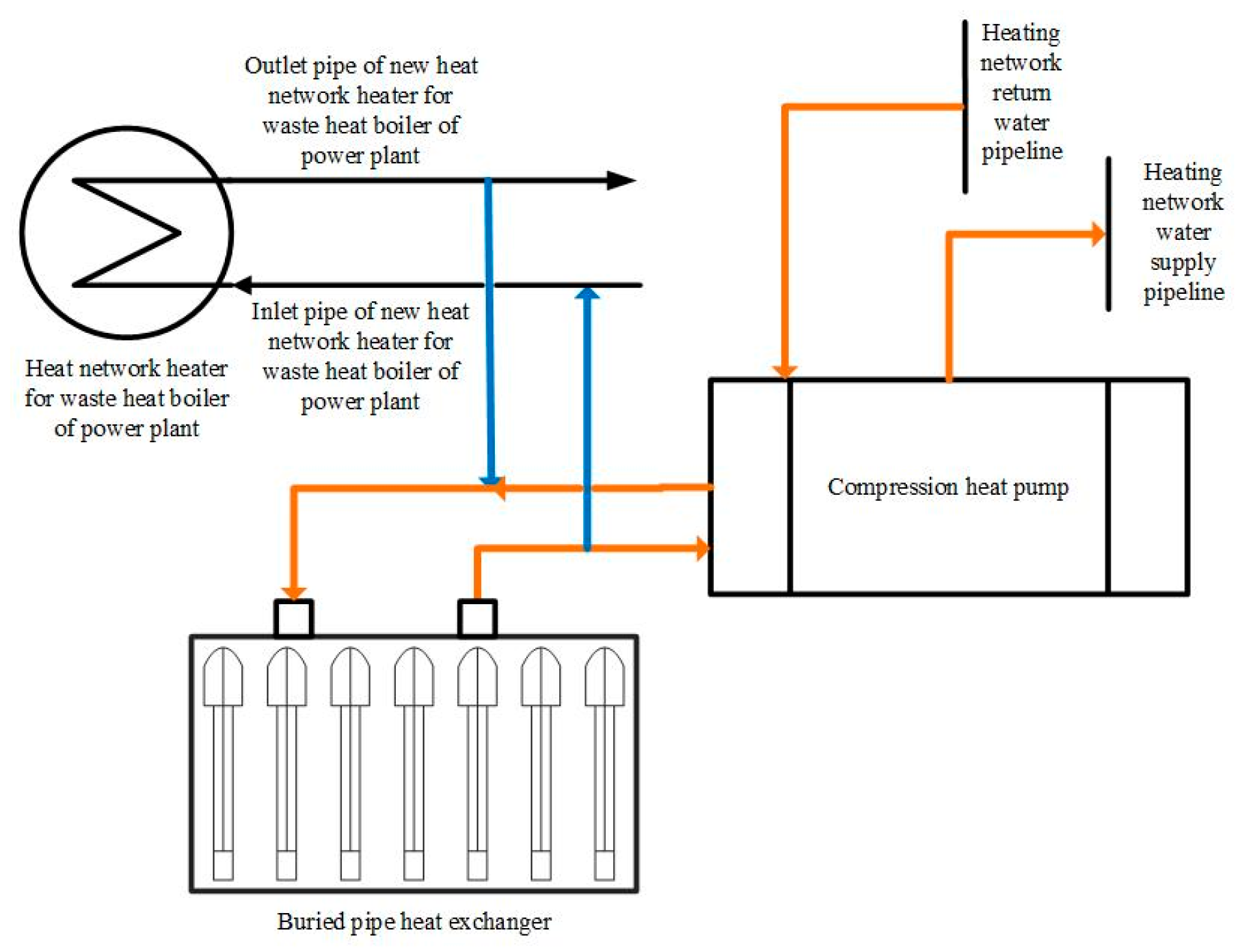
To achieve the cross-seasonal storage of waste heat from power plant flue gas, a buried pipe system was developed, as shown in Figure 1. During the heat storage period, the circulating medium enters the heat network heater of a waste heat boiler and is heated by flue gas, and the medium then enters the buried pipe heat exchanger to heat the underground soil for heat storage. After heat release, the circulating medium enters the heat recovery boiler again and is heated, entering the next heat storage cycle. During the heat release period, the heat stored in the soil is used as a low-temperature heat source for the ground-source heat pump unit to heat the return water of the heating network. The circulating medium enters the buried pipe heat exchanger to absorb soil heat. After absorbing heat, the circulating medium releases heat through the evaporator of a ground-source heat pump unit, driving the unit to heat the circulating water in the heating network. After heat release, the circulating medium is led out of the outlet of the evaporator, then enters the buried pipe to absorb heat, entering the next heat release cycle.
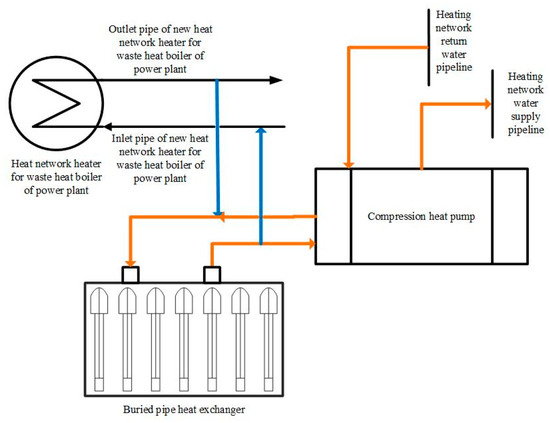
Figure 1.
Schematic diagram of cross-seasonal storage system for flue gas waste heat in power plants.
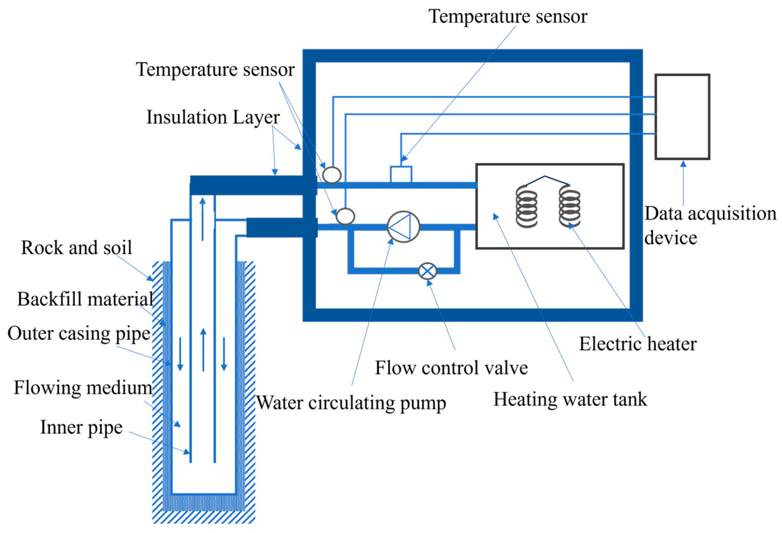
The experimental device adopts a testing system based on the principle of on-site thermal response for underground buried pipes. This device can complete thermal response tests at different inlet temperatures and underground rock and soil thermal property tests, as shown in Figure 2. The device includes an electric heater, an insulated water tank, an electric control cabinet, a circulating water pump, flow meters, flow control valves, connecting pipelines and their accessories, insulation materials, a temperature measurement system, and an automatic data acquisition system. The experimental data are collected and stored automatically, and the collection time interval can be flexibly set according to the user’s needs.
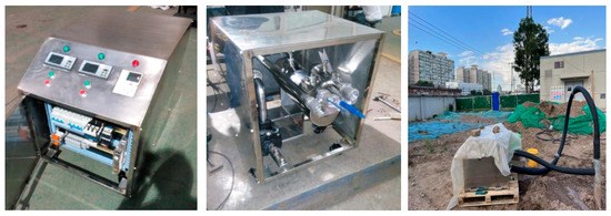
Figure 2.
Experimental system installation diagram.
The on-site testing system includes a circulation system, a heating system, a measurement system, and auxiliary equipment. The circulation circulates water in underground buried pipe heat exchangers and measuring instruments and regulates the flow rate of circulating water. The heating part is used to heat the circulating water so that heat lost by the water during the process can be replenished. The measurement system measures the water temperature of the inlet and outlet water of the heat exchanger and the flow rate of the circulating water. This is achieved using two temperature sensors and one flow meter. Two temperature sensors are installed on the pipes of the measuring instrument for the outlet and return water. The flowmeter is installed on the return water pipeline of the measuring instrument. The auxiliary equipment includes a power supply for the measuring instruments, heating power regulation, and auxiliary temperature measurement devices. Figure 3 shows a schematic diagram of the experimental system setup, in which the heater heats the water in the water tank with a constant thermal power. The heated circulating water enters the underground heat exchanger at a constant flow rate and exchanges heat with the surrounding soil. At the same time as the heater starts heating, timing begins, and the inlet and outlet water temperatures of the underground heat exchanger are recorded at certain time intervals to determine the average inlet and outlet water temperature and the heat exchange per unit depth of the buried pipe.

Figure 3.
Schematic diagram of thermal response testing system for casing-shaped buried pipes.
This experiment has one test well (hole); the relevant technical parameters are shown in Table 1. After drilling, we wait for the heat exchanger to pass the water and pressure test before lowering the pipe. To reduce heat loss in the connecting pipes, 20 mm thick rubber insulation material is used to insulate the connecting pipes in the horizontal section, as shown in Figure 2.

Table 1.
Technical parameters related to experimental wells.
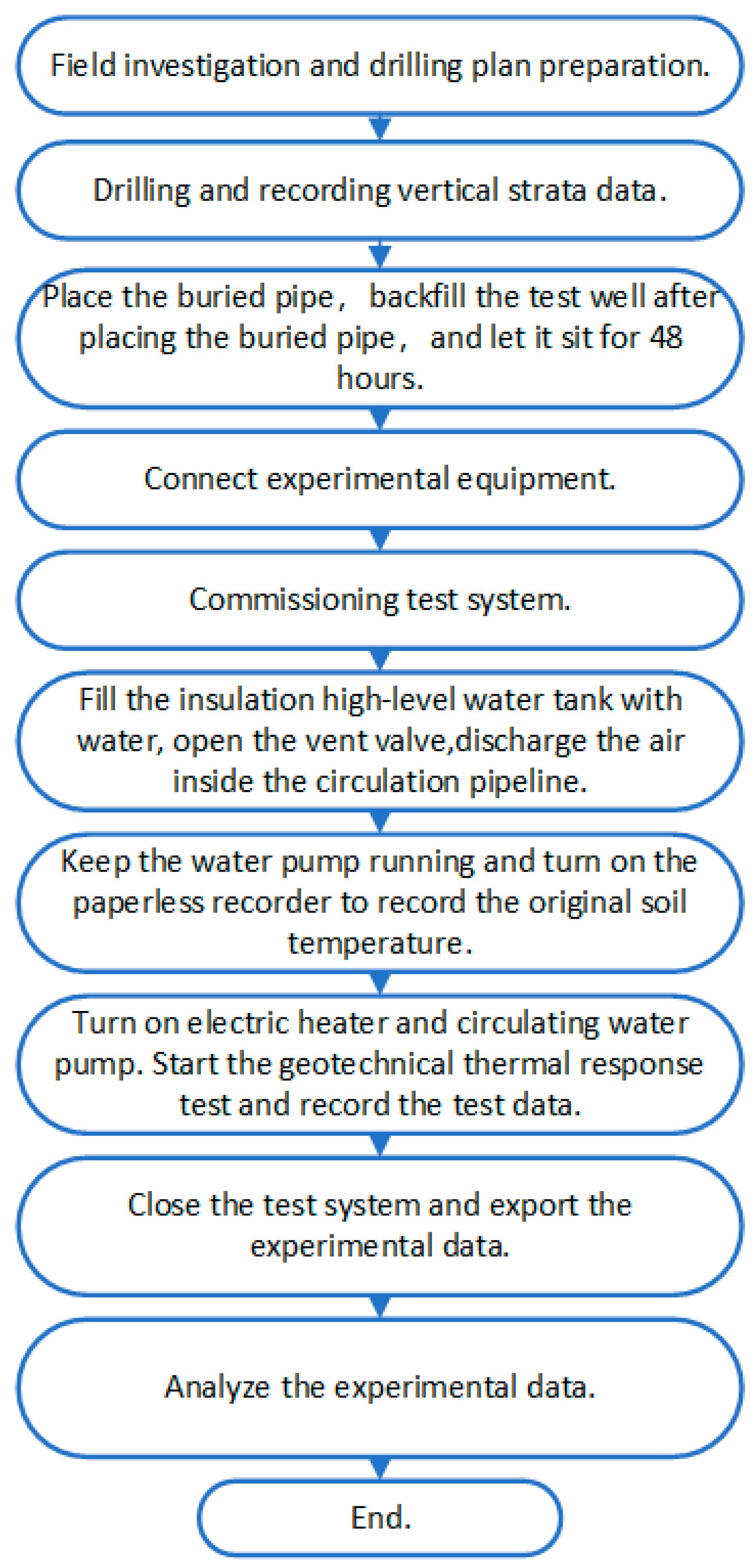
The specific steps of the geotechnical thermal response test are as follows:
- (1)
- Field investigation and drilling plan preparation: Conducting an on-site investigation is a necessary preparation condition before conducting thermal response testing. We determine the number and location of test holes, as well as the required cable models and lengths, based on the actual situation, terrain, topography, and water and electricity conditions of the project site. The relevant technical parameters of the experimental well are shown in Table 1.
- (2)
- Drilling and recording vertical strata data: Before conducting the thermal response test, the drilled rock layer data are recorded during the process of opening the test well, and an outer-rock-layer data map of the rock and soil is drawn in the vertical direction.
- (3)
- The buried pipe is placed, and the test well is backfilled after the placement. Special backfill material is used to fill the casing and surrounding soil of the jacketed heat exchanger. After the backfilling, the test well is left for at least 48 h to keep the drilling medium and backfill material temperatures as consistent as possible with the original ground temperature.
- (4)
- The experimental site is leveled to ensure that the experimental equipment is placed flat, facilitating the operation of the experiment. The equipment is transported to the edge of the borehole, minimizing the length of exposed pipelines and minimizing heat loss caused by pipelines. During the process of connecting equipment and drilling, unnecessary bends, valves, and reducers are reduced. The exposed parts of the equipment are insulated with material with a thickness generally greater than 20 mm.
- (5)
- Commissioning the test system: Connecting the testing equipment to external conditions such as water and electricity follows a particular order. First, the water is generally connected, and then the electricity. The equipment is then connected to the buried pipe and the water replenishment pipe. After the water pipe equipment is connected and checked for leaks, the power electricity is connected to the project site, and the equipment is debugged.
- (6)
- The insulated high-level water tank is filled with water, and the vent valve is opened. We use the height difference between the water tank and the vent valve to discharge the air inside the circulation pipeline and then connect the power supply to confirm its safety. The circulating water pump is turned on to keep the water inside the pipeline in a circulating state, and the automatic vent valve discharges the residual gas in the pipeline. Due to the large water capacity of sleeve-type buried pipe systems, the continuous process of circulating water for exhaust is relatively lengthy, usually lasting about 3 h. When the circulating water flow is stable, and there is no gas discharge from the automatic vent valve, the test state can be entered.
- (7)
- After the gas is completely discharged, we keep the water pump running and turn on a paperless recorder to record the original soil temperature.
- (8)
- After the initial ground temperature test of the rock and soil, the electric heater is turned on while keeping the circulating water pump turned on, and stable power heating is carried out on the circulating water while maintaining the voltage and current. At this time, the volume average circulating flow rate of the circulating medium is 4 m3/h. We then use a recorder to document the inlet and outlet temperature, flow rate, heating power, pressure, and other data from the heat exchanger. The data collection time interval is 30 s, and the testing time is no less than 48 h. The temperature fluctuation in the local buried pipe return water compared with 12 h ago is no greater than 1 °C. The data from the recorder are then exported for storage.
- (9)
- After the test, the closing order is reversed from the opening order. After exporting the data from the paperless recorder, the recorder is closed, and the circulating water pump is turned off. The geotechnical thermal response experimental equipment is then dismantled.
- (10)
- The data from the paperless recorder are analyzed and processed to ascertain the comprehensive thermal property parameters of the test well in the plot.
A flowchart of the experiment is shown in Figure 4.
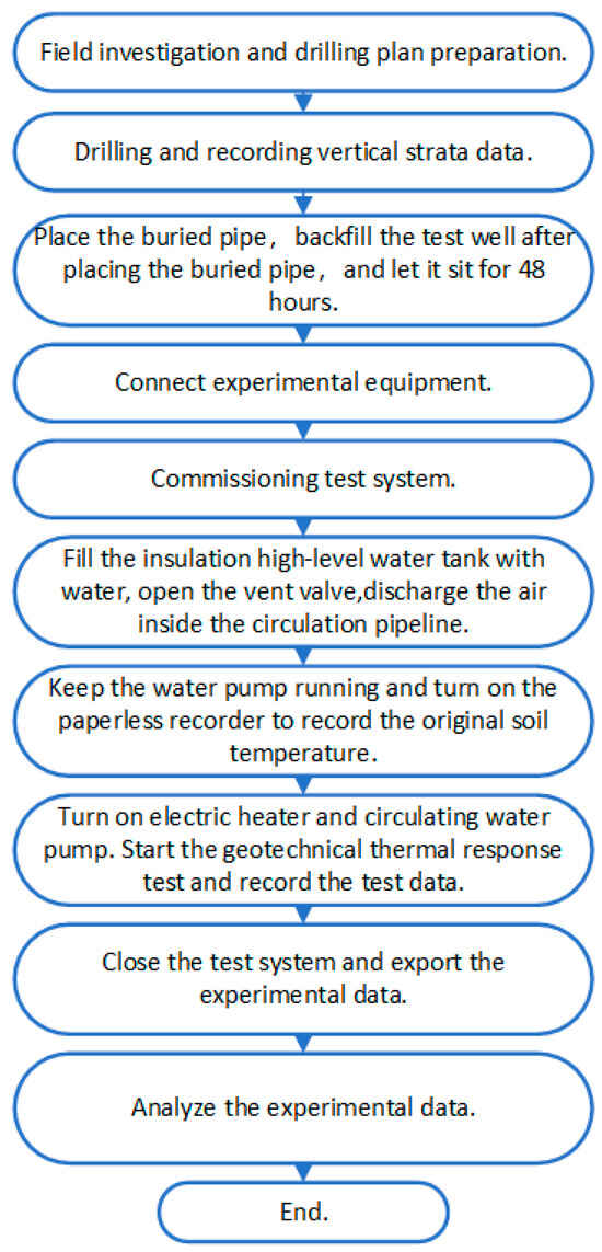
Figure 4.
Experiment flowchart.
2.3. Experimental Uncertainty Analysis
The details of the uncertainty control of each link in the test system are shown in Table 2.
Table 2.
Uncertainty control table.
Reducing measurement error is an important index in this geotechnical thermal response experiment. Our analysis shows that the calculated error mainly comprises instrument test error and external environment error. According to error analysis theory, the total control error of the measurements should be 5%. The relative error of the calculation results is
where δk/k is the error in the test data analysis results, δX/X is the error in measuring the depth of the heat exchanger, and σY/Y is the error of the test instrument. Error calculation result of experimental system is shown in Table 3.
Table 3.
Error calculation table of experimental system.
2.4. Data Processing
In sleeve-type buried pipes, it is necessary to reverse-calculate the thermal properties of rock and soil based on changes in the average temperature of the relevant fluid. Therefore, the heat transfer model of buried pipes in this study adopts the classic line heat source model for analysis.
The heat transfer process of buried pipes from the inside out is very complex, and their heat transfer capacity is affected by many factors, including local geological conditions, vertical depth of buried pipes, buried pipe form, and underground water content. To analyze and solve the heat transfer process of sleeve heat exchangers, we make the following simplified assumptions for the analysis model:
- (1)
- The thermal properties of backfill materials and surrounding rock and soil are uniform and consistent, and their thermal properties parameters do not vary with changes in radial and vertical dimensions;
- (2)
- There is no thermal conduction in the vertical direction; that is, heat transfer is a two-dimensional problem along the radial direction of the buried pipe;
- (3)
- The temperature of the fluid inside the buried pipe is uniform, and the heat return problem of the fluid inside and outside the casing in the casing-shaped buried pipe heat exchanger is not considered;
- (4)
- There is no contact thermal resistance between the contact surfaces; that is, there is no contact gap between materials.
Based on the simplification and assumptions above, the original heat transfer model is shown in Figure 5.
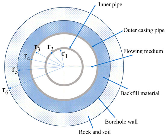
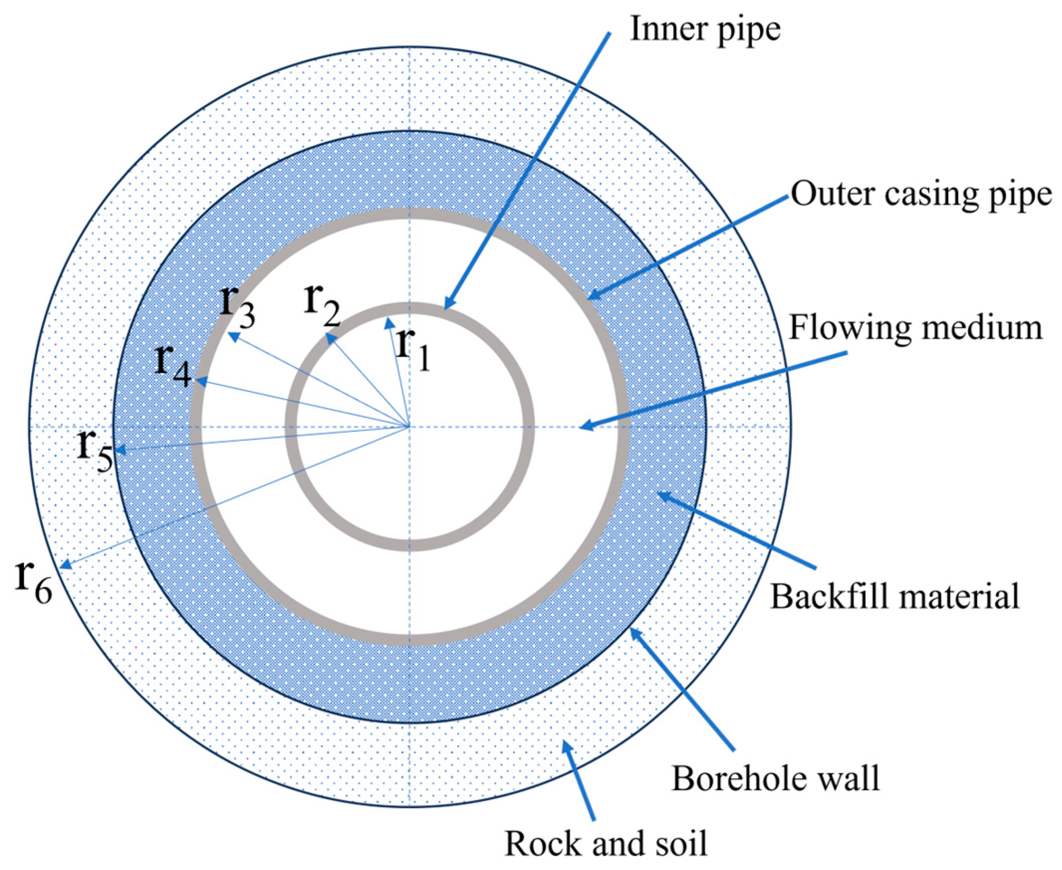
Figure 5.
Heat transfer model of casing-shaped buried pipe heat exchanger.
All dimensions in the figure are for the casing-shaped buried pipe heat exchanger, where r1 is the inner wall radius of the inner pipe; r2 is the outer wall radius of the inner casing: r3 is the inner wall radius of the outer-casing pipe; r4 is the outer wall radius of the outer-casing pipe; r5 is the radius of the inner wall of the borehole; and r6 is the geotechnical calculation boundary.
Taking a unit length of the buried pipe as the research subject, according to the theory of heat transfer, it can be concluded that for the inner wall of the outer-casing pipe,
where hf is the convective heat transfer coefficient between the wall and its internal medium; T3 is the temperature of the inner wall of the outer-casing pipe, k; Tf is the fluid temperature inside the casing-shaped buried pipe heat exchanger, k; and Rf is the convective heat transfer resistance between the wall and its internal medium.
According to the theory of heat transfer, it can be concluded that for the thermal conductivity process of the outer-casing pipe,
where T4 is the outer wall temperature of the outer-casing pipe, k; λ1 is the thermal conductivity of the outer-casing pipe material, W/(m·k); and Rp is the thermal resistance of the outer-casing pipe of the casing-shaped buried pipe heat exchanger.
The heat transfer process of the backfill material from the outer casing to the inner wall of the drilling well can be determined using heat transfer theory:
where T5 is the borehole wall temperature of the casing-shaped buried pipe heat exchanger, k; λ2 is the thermal conductivity of the backfill material, W/(mm·k); and Rh is the thermal resistance of the backfill material of the casing-shaped buried pipe heat exchanger.
Thus, the total thermal resistance of the borehole is
Rn = Rf + Rp + Rh
To promote heat exchange, the medium velocity in the buried pipe should ensure that the circulating medium is always in a turbulent state. The Bittus–Boelter formula is used to calculate the Nusselt number:
where Nu is the Nusselt number, Re is the Reynolds number, and Pr is the Prandtl number.
where u is fluid velocity, m/s; v is kinematic viscosity, and m′/s; de is equivalent diameter, four times the wet area compared with the upper wet perimeter, m;
The circulating medium in the buried pipe is turbulent, and the convective heat transfer coefficient between the inner wall of the buried pipe and the fluid, hf, is
We bring Formula (7) into Formula (2) to calculate the convection heat transfer resistance, Rf, on the inner wall of the casing and bring Formulas (3) and (4) into Formula (5) to calculate the heat transfer resistance, Rn, of the borehole.
Kelvin’s infinite line heat source model is used for the heat transfer process of the casing-shaped buried pipe heat exchanger in the rock and soil outside the drilling area. The model is a process of heat extraction and release in infinite rock and soil, with the same heat released uniformly throughout the unit length. The temperature field formed during heat extraction and release is a two-dimensional radial temperature field centered on the heat source. First, the initial temperature of the rock and soil is considered a certain value from top to bottom, that is, the original ground temperature. A linear heat source with uniform heat generation per unit length is placed along the vertical direction of the well, and its heat flow intensity is q (W/m).
The excess temperature is defined as
According to Carslaw and Jaeger [23], the excess temperature at a certain point in space can be expressed as follows:
where Ei(x) refers to the exponential integration formula:
We bring Formula (9) into Formula (10) and simplify it to obtain
Given that the thermal diffusivity of rock and soil is α = λ/ρc, m/s, this is carried over to Formula (12):
When the required temperature is the same as that of the borehole wall, and r = r5 = d5/2, the above formula can be abbreviated as
When the time is long enough,
When x > 5, the error of the above approximate formula will not exceed 2%. By introducing Formula (15) into Formula (14), the variation in the borehole wall temperature with time τ can be determined as follows:
For the heat transfer process outside the borehole, the thermal resistance, Rw (formation thermal resistance), at τ can be expressed as
Let
Then, Formula (16) can be rewritten as
According to Formula (18), under the given drilling conditions, the temperature of rocks and soil at an infinite distance and their thermal physical parameters are fixed values; thus, A and B are fixed values, and the inner wall temperature of the drilling area is linearly correlated with the natural logarithm of time.
Given that the thermal physical parameters of underground soil cannot be directly measured by instruments like temperature, flow, pressure, and other parameters, they can only be solved by measuring heat flow and temperature according to heat transfer theory, applying Fourier heat conduction law and the heat transfer model. The method involves taking the experimental data from the computer and comparing them with the results calculated by the heat transfer model. Thus, when the variance sum, f, reaches the minimum value, the thermophysical parameters adjusted by the heat transfer model are the calculated results.
where T_(cal, i) is the average temperature of the fluid in the buried pipe calculated by the model at time i, T_(exp, i) is the average temperature of the fluid in the buried pipe actually measured at time i, and N is the number of data groups measured in the experiment.
3. Results
3.1. Soil Geological Composition and Initial Average Temperature
According to the on-site sampling conducted during on-site test hole drilling, the geological composition of the 300 m deep buried pipe site can be obtained, as shown in Table 4. Due to different geological structures in different regions, the difficulty and cost of drilling can vary. Given the feedback of the site’s drilling situation and the geological composition of its different depths, a pebble layer and conglomerate layer in the geological composition will greatly increase the difficulty and cost of drilling.
Table 4.
Geological composition of test plot.
The no-load cycling method tests the initial average temperature of rock and soil. Before the test, the test hole is connected to the inlet and outlet of the circulating water pipeline of the aboveground test device, and the exposed pipeline is insulated. Under the premise of not opening the heater, the circulating water pump is only used to keep the water flowing inside the heat exchanger, and the temperature of circulating water is recorded by the temperature sensor. After a long cycle, the unstable data in the initial stage are discarded, and the average value of the water temperature record in the stable stage is taken as the original ground temperature of the soil (the change in the outlet temperature of the buried pipe for 12 h is no greater than 0.5 °C). Using this method, the on-site no-load test runs for 16 h, and the outlet water temperature of the buried pipe continuously changes by less than 0.5 °C from the 1st hour to the 16th hour. Finally, the initial average soil temperature in the buried pipe site is 16.7 °C.
3.2. Soil Thermophysical Properties
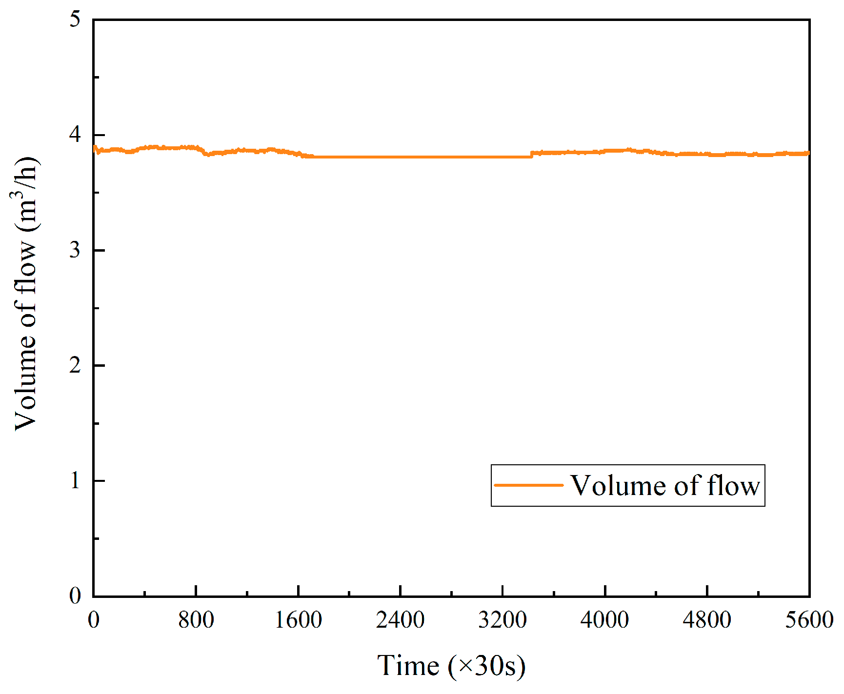
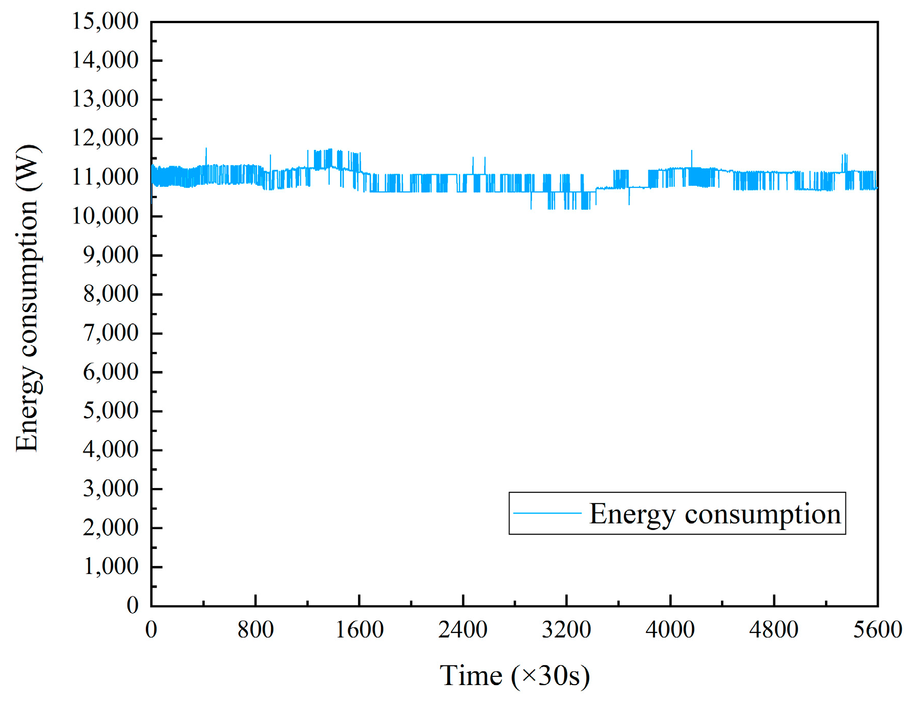
The geotechnical thermal response experiment method in Section 2 is used for this test. Variations in circulating medium flow in the buried tube heat exchanger with time are shown in Figure 6. The circulating medium flow in the casing-shaped buried pipe heat exchanger is relatively stable without obvious fluctuation, and the average flow is basically maintained at 3.84 m3/h, meeting the requirement of maintaining the fluid in the heat exchanger in a turbulent state. Variations in the heat release power of the casing-shaped buried pipe heat exchanger with time are shown in Figure 7. The heat release power of the buried tube fluctuates around 11,000 W during the entire testing process, with a floating range of about 7%. The average heat release power was 10,966 W.
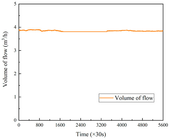
Figure 6.
Variations in circulating flow rate in casing-shaped buried pipe heat exchanger with test time.
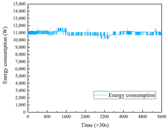
Figure 7.
Variations in total heat release in casing-shaped buried pipe heat exchanger with test time.
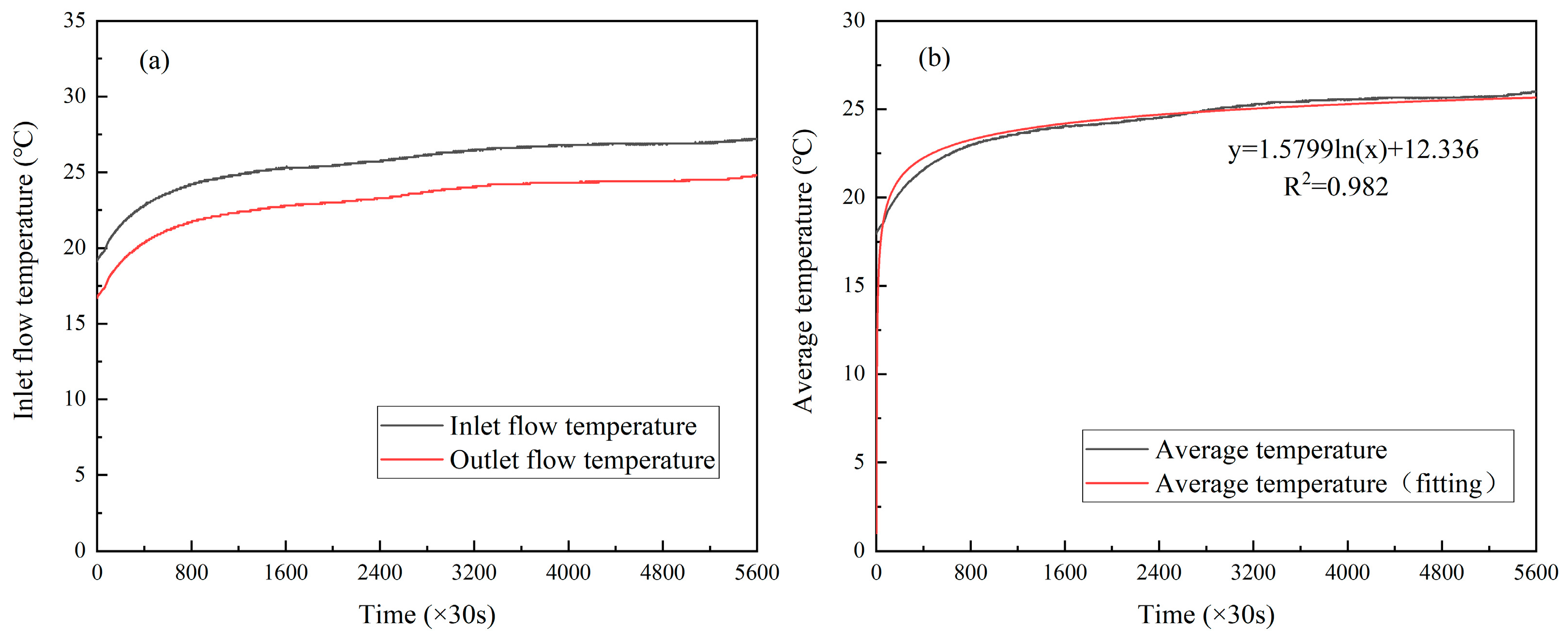
Figure 8a shows that when the circulating medium flow rate and heat release power in the casing-shaped buried pipe heat exchanger in the test hole are fixed, the fluid inlet and outlet temperatures in the heat exchanger vary with time. The fluid temperature at the inlet and outlet of the heat exchanger gradually increases with time. This is because the heat release of the heat exchanger heats the surrounding rock and soil. To maintain the heat release power of the heat exchanger, the temperature of the circulating medium needs to be increased accordingly. We can calculate the average temperature at the inlet and outlet and fit it according to Kelvin’s model. The results are shown in Figure 8b.
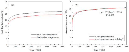
Figure 8.
(a) Variations in inlet and outlet fluid temperature of casing-shaped buried pipe heat exchanger with test time. (b) Variations in average fluid temperature of casing-shaped buried pipe heat exchanger with test time.
According to the fitting results, A = 1.5799, and B = 12.336. The thermal physical parameters of underground rock and soil in the area can be obtained through reverse calculation: the equivalent thermal conductivity (λ) of the test hole is 1.97 W/(m∙K), the equivalent volumetric specific heat capacity (Cv) is 2655 kJ/(m3∙K), and the thermal resistance of the unit length of the hole (R) is 0.353 (m∙K)/W.
3.3. Analysis of Heat Transfer Capacity of Buried Pipe Heat Exchanger
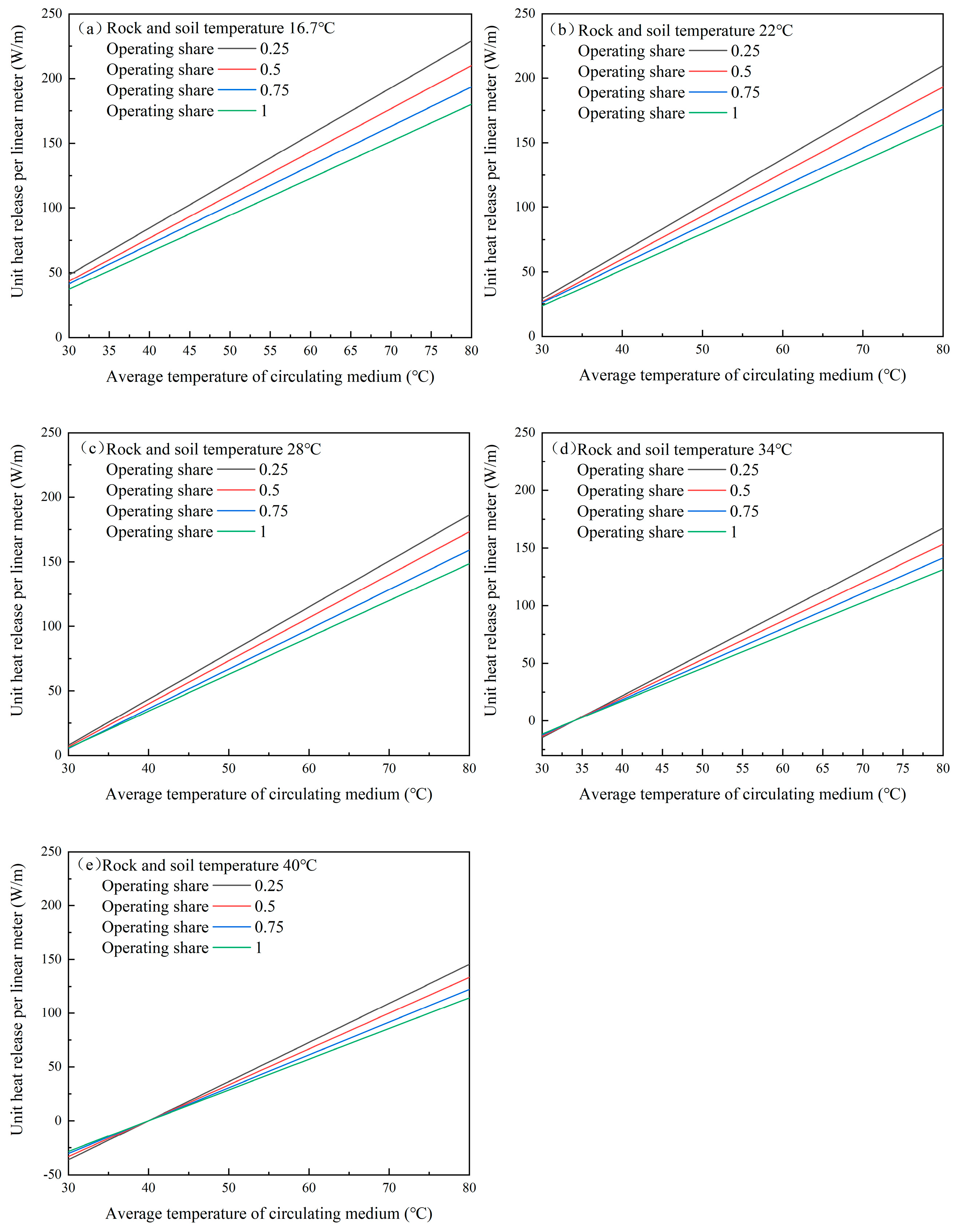
When the heat storage period arrives, the buried pipe heat exchanger stores the waste heat of the power plant flue gas in the soil. Figure 9a–e show variations in heat per unit linear meter in the heat exchanger with the average temperature of the circulating medium under different rock and soil temperatures and operating shares.
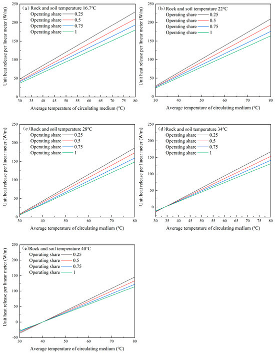
Figure 9.
Variation curve of unit linear meter heat release with average temperature of circulating medium in heat exchanger under heat release conditions (a) at average temperature of 16.7 °C; (b) at average temperature of 22 °C; (c) at average temperature of 28 °C; (d) at average temperature of 34 °C; (e) at average temperature of 40 °C.
When the circulating medium is hotter than the rock and soil, the similarity of the rock/soil temperature and the average temperature of the circulating medium will decrease the heat release per unit linear meter as the operating share increases. In the ground-source heat pump system, waste heat from flue gas is discharged into the soil and rock mass through the heat exchanger. However, the heat exchange state between the underground heat exchanger and the soil and rock mass is an unstable heat transfer. The heat discharge is centered on the heat exchanger and gradually spreads to the surrounding rock and soil. As the operating share increases, the daily operating time of the heat exchanger also increases. Due to the inherent thermal resistance of soil, the heat released by the heat exchanger cannot be quickly transferred elsewhere, increasing the soil temperature near the heat exchanger and affecting further heat transfers, thus affecting the heat transfer per linear meter. With increased total emissions, a large amount of heat accumulates in the rock and soil near the heat exchanger well group, and heat diffusion gradually slows down. The heat transfer capacity of the underground heat exchanger continues to decline.
In addition, Figure 9d shows that when the rock and soil temperature equals the average temperature of the circulating medium (34 °C), the heat release per linear meter curves of the different operating shares intersect at the zero point of heat release per linear meter. Similarly, Figure 9e shows that this phenomenon also occurs when the rock and soil temperature equals the average temperature of the circulating medium (40 °C). This is because when the rock and soil temperature is the same as that of the circulating medium, the heat exchange between the buried pipe heat exchanger and the surrounding rock and soil ends. At this time, no matter how much the operation share changes, the heat release per unit linear meter will be 0 MW/m.
When the temperature of the circulating medium is less than the surrounding rock and soil temperature, the buried pipe heat exchanger changes from releasing heat to absorbing heat. Therefore, the variation trend of the heat release per unit linear meter with the operating share is the opposite.
With the increased average temperature of the circulating medium, the heat release per linear meter increases linearly with the same rock and soil temperature and operating share. Under a 25% operating share, the heat release increases by 3.6~3.7 w/m for every 1 °C increase in the average temperature of the circulating liquid; under a 50% operating share, the heat release increases by 3.3~3.4 w/m for every 1 °C increase in the average temperature of the circulating liquid; under a 75% operating share, the heat release increases by 3~3.1 w/m for every 1 °C increase in the average temperature of the circulating liquid; under a 100% operating share, the heat release increases by 2.7~2.8 w/m for every 1 °C increase in the average temperature of the circulating liquid. This is because the average temperature of the circulating medium increases, increasing the temperature difference between the circulating medium and the surrounding rock and soil, which is beneficial to heat transfer.
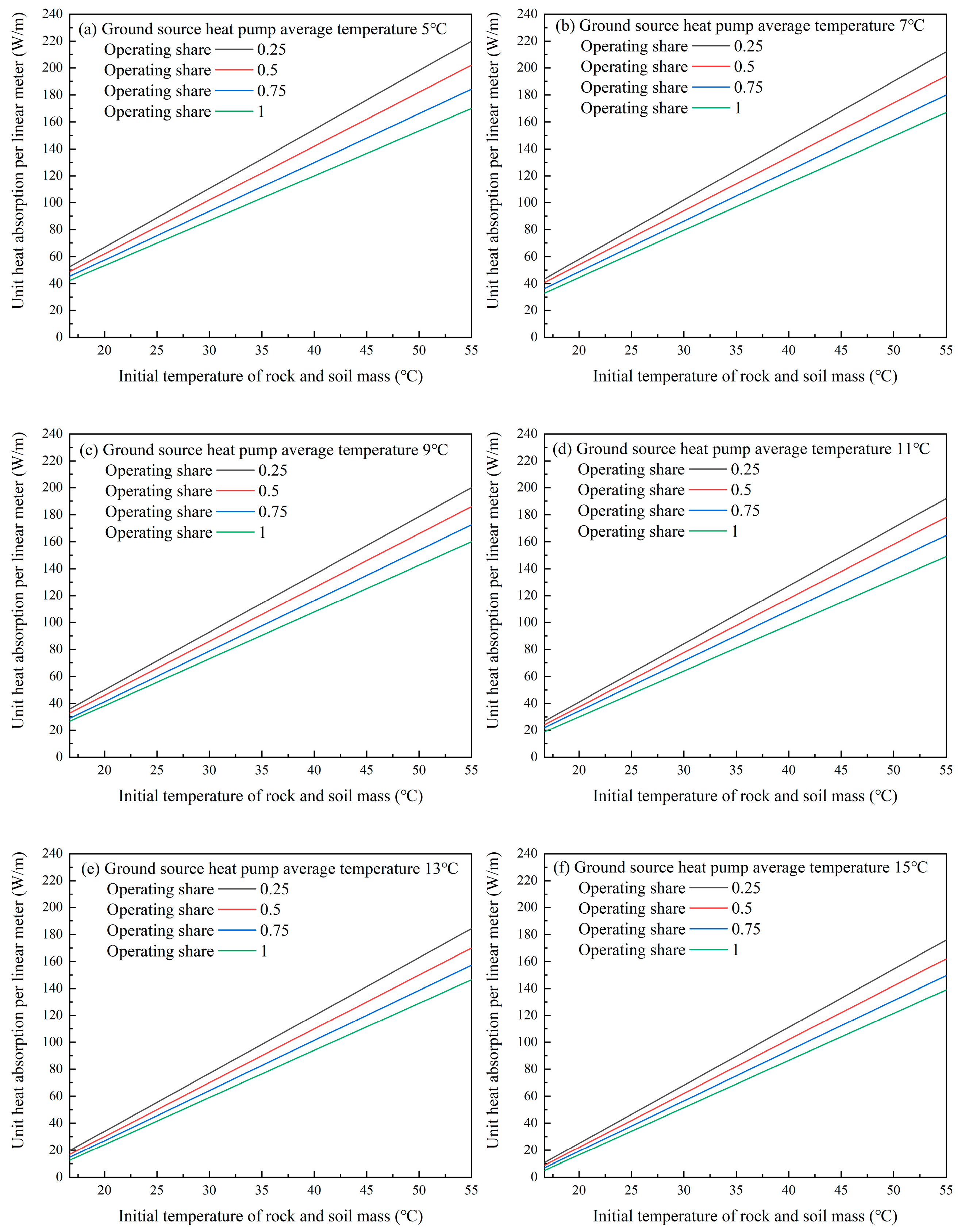
When the heating period comes, the ground heat pump releases the soil heat to heat the circulating water of the heat supply network. Figure 10a–f show variations in the heat absorption per unit linear meter of the heat exchanger with an initial rock and soil temperature under different ground-source heat pump host average temperatures and operating share conditions. Figure 10a–f show that the heat absorption per linear meter decreases with the increased operating share under the same rock and soil initial temperature and ground-source heat pump host average temperature.
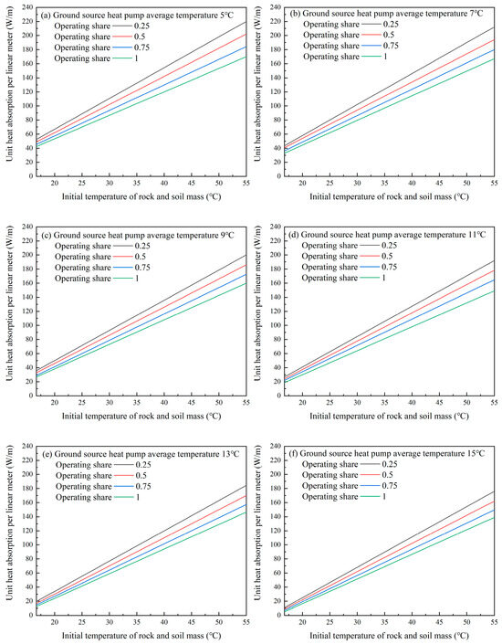
Figure 10.
Variation curve of unit linear meter heat release with initial rock and soil mass temperature under soil heat release conditions (a) at ground source heat pump average temperature of 5 °C; (b) at ground source heat pump average temperature of 7 °C; (c) at ground source heat pump average temperature of 9 °C; (d) at ground source heat pump average temperature of 11 °C; (e) at ground source heat pump average temperature of 13 °C; (f) at ground source heat pump average temperature of 15 °C.
The soil heat is discharged from the heat pump system into the circulating water through the heat exchanger. As the operating share increases, the daily operating time of the heat exchanger also increases. Due to the inherent thermal resistance of the soil, the heat from other parts of the soil cannot be diffused to the heat exchanger in time, decreasing the soil temperature near the heat exchanger and affecting the further heat absorption per linear meter.
With increased rock and soil temperature, the heat absorption per linear meter increases linearly when the operating share and ground-source heat pump host average temperatures are certain. Under a 25% operating share, heat absorption increases by 4.4~4.5 w/m for every 1 °C increase in rock and soil temperature; under a 50% operating share, heat absorption increases by 3.9~4.0 w/m for every 1 °C increase in rock and soil temperature; under a 75% operating share, the heat absorption increases by 3.7~3.8 w/m for every 1 °C increase in rock and soil temperature; and under a 100% operating share, the heat absorption increases by 3.4~3.5 w/m for every 1 °C increase in rock and soil temperature. The higher the initial soil temperature, the greater the temperature difference inside and outside the buried pipe heat exchanger, which is more conducive to heat exchange and improves the heat absorption per linear meter.
4. Conclusions
A geotechnical thermal response experiment was carried out. The drilling process demonstrated a pebble layer and a conglomerate layer in an area’s geological composition will greatly increase the difficulty and cost of drilling. In this experimental area in Beijing, the equivalent thermal conductivity (λ) of the test hole was 1.97 W/(m∙K), the equivalent volumetric specific heat capacity (Cv) was 2655 kJ/(m3∙K), and the thermal resistance of the unit length of the hole (R) was 0.353 (m∙K)/W. The heat transfer performance of a buried pipe heat exchanger was studied. An increase in operating share will decrease the heat transfer of the buried pipe heat exchanger. The heat release increases with the average temperature of the circulating medium in heat release mode. The heat absorption increases with the rock and soil temperature in heat absorption mode. These observations can guide the design of promotion and application plans for this technology in North China.
Author Contributions
F.Y.: conceptualization, visualization, validation, investigation, methodology, formal analysis, writing—original draft, writing—review and editing, resources. M.L.: writing—review and editing. Y.S.: formal analysis. X.F.: supervision. L.Z.: supervision. S.M.: conceptualization, visualization, validation, investigation, methodology, formal analysis, writing—original draft, writing—review and editing, resources, supervision. All authors have read and agreed to the published version of the manuscript.
Funding
This research received no external funding.
Data Availability Statement
All data used will be made available by the corresponding author upon reasonable request.
Conflicts of Interest
Authors Fan Yang, Yu Shen, Lijun Zheng, Xinyue Fang and Siming Ma were employed by the company Huadian Electric Power Research Institute Co., Ltd. The remaining authors declare that the research was conducted in the absence of any commercial or financial relationships that could be construed as a potential conflict of interest.
Abbreviations
The following abbreviations are used in this manuscript:
| UTES | Underground thermal energy storage |
| DOAJ | Energy conservation and energy storage |
| WTES | Water tank thermal energy storage |
| GWTS | Gravel–water pit thermal energy storage |
| ATES | Aquifer thermal energy storage |
| BTES | Buried pipe thermal energy storage |
| λ | Thermal conductivity |
| Cv | Volumetric specific heat capacity |
| R | Thermal resistance of the unit length of the hole |
References
- Administration, N.E. Renewable Energy Generation Increased by 20% Year-on-Year in the First Three Quarters. Available online: https://www.nea.gov.cn/ (accessed on 11 December 2024).
- Statistics, N.B.O. Annual Data. Available online: https://www.stats.gov.cn (accessed on 9 December 2022).
- Reed, A.L.; Novelli, A.P.; Doran, K.L.; Ge, S.; Lu, N.; McCartney, J.S. Solar district heating with underground thermal energy storage: Pathways to commercial viability in North America. Renew. Energy 2018, 126, 1–13. [Google Scholar] [CrossRef]
- IEA. Technology Collaboration Programme-Energy Storage Through Energy Conservation. Available online: https://iea-eces.org/news/annual-report-2018 (accessed on 18 July 2018).
- Giordano, N.; Comina, C.; Mandrone, G.; Cagni, A. Borehole thermal energy storage (BTES). First results from the injection phase of a living lab in Torino (NW Italy). Renew. Energy 2016, 86, 993–1008. [Google Scholar] [CrossRef]
- Hendriks, M.M.; Velvis, H. Operational management of large scale UTES systems in Hospitals. In Proceedings of the Innostock 2012 the 12th International Conference on Energy Storage, Lleida, Spain, 16–18 May 2012. [Google Scholar]
- Nubicker, J.; Mangold, D.; Heidemann, W.; Müller-Steinhagen, H. Solar Assisted District Heating System with Duct Heat Store in Neckarsulm-Amorbach (Germany). In Proceedings of the Proceedings ISES Conference 2003, Göteborg, Sweden, 14–19 June 2003. [Google Scholar]
- Baser., T.; McCartney., J.S. Development of a Full-Scale Soil-Borehole Thermal Energy Storage System. In Proceedings of the IFCEE 2015, San Antonio, TX, USA, 17–21 March 2015; pp. 1608–1617. [Google Scholar]
- Hawes, D.W.; Feldman, D.; Banu, D. Latent heat storage in building materials. Energy Build. 1993, 20, 77–86. [Google Scholar] [CrossRef]
- Hesaraki, A.; Holmberg, S.; Haghighat, F. Seasonal thermal energy storage with heat pumps and low temperatures in building projects—A comparative review. Renew. Sustain. Energy Rev. 2015, 43, 1199–1213. [Google Scholar] [CrossRef]
- Lundh, M.; Dalenbäck, J.O. Swedish solar heated residential area with seasonal storage in rock: Initial evaluation. Renew. Energy 2008, 33, 703–711. [Google Scholar] [CrossRef]
- Sibbitt, B.; McClenahan, D.; Djebbar, R.; Thornton, J.; Wong, B.; Carriere, J.; Kokko, J. The Performance of a High Solar Fraction Seasonal Storage District Heating System–Five Years of Operation. Energy Procedia 2012, 30, 856–865. [Google Scholar] [CrossRef]
- Xu, L.; Torrens, J.I.; Guo, F.; Yang, X.; Hensen, J.L.M. Application of large underground seasonal thermal energy storage in district heating system: A model-based energy performance assessment of a pilot system in Chifeng, China. Appl. Therm. Eng. 2018, 137, 319–328. [Google Scholar] [CrossRef]
- Zhao, J.; Chen., Y.; Li., X. Optimization for heat storage operating modes based on simulation of seasonal underground storage of solar-GSHP system. J. North China Electr. Power Univ. (Nat. Sci. Ed.) 2007, 34, 74–77. [Google Scholar] [CrossRef]
- Han, M.; Qu., H.; Li., X.; Zhao., J.; Cui, J. Theoretical research on underground heat storage performance of ground coupled heat pump system with seasonal storage. J. Sol. Energy 2008, 29, 920–926. [Google Scholar] [CrossRef]
- Liu, X. Underground Heat Transfer Analysis and Engineering Application of Based on Seasonal Solar Thermal Storage Underground Pipe; Shandong Jianzhu University: Jinan, China, 2016. [Google Scholar]
- Han, M. Heat Transfer Analysis of Buried Pipes Underground Seasonal Thermal Storage; Shandong Jianzhu University: Jinan, China, 2013. [Google Scholar]
- Zhang, W. Study on the Seasonal Soil Heat Storage Characteristics in a Solar Ground Coupled Heat Pump System in Severe Cold Areas; Harbin Institute of Technology: Harbin, China, 2010. [Google Scholar]
- Wang, X. Operating Characteristics and Optimization of the Solar-Ground Coupled Heat Pump System with Seasonal Storage; Harbin Institute of Technology: Harbin, China, 2011. [Google Scholar]
- Chen, Y. Research on the Mode Selection of Ground-Source Sides of Solar Groud-Source Heat Pump Air Conditioning System; Hebei University of Technology: Tianjin, China, 2016. [Google Scholar]
- Wang, M. Research on the Control Strategy of Solar-Ground Source Heat Pump System; Hebei University of Technology: Tianjin, China, 2016. [Google Scholar]
- Yang, W.; Chen., Z.; Si., M. Underground energy storage and release characteristics of ground source heat pump with seasonal energy storage. J. Southeast Univ. (Nat. Sci. Ed.) 2010, 40, 973–978. [Google Scholar] [CrossRef]
- Carslaw, H.S.; Jaeger., J.C. Conduction of Heat in Solids, 2nd ed.; Oxford University Press: Oxford, UK, 1959. [Google Scholar]

Disclaimer/Publisher’s Note: The statements, opinions and data contained in all publications are solely those of the individual author(s) and contributor(s) and not of MDPI and/or the editor(s). MDPI and/or the editor(s) disclaim responsibility for any injury to people or property resulting from any ideas, methods, instructions or products referred to in the content. |
© 2025 by the authors. Licensee MDPI, Basel, Switzerland. This article is an open access article distributed under the terms and conditions of the Creative Commons Attribution (CC BY) license (https://creativecommons.org/licenses/by/4.0/).