1. Introduction
Adsorption chillers are usually driven by heat, so these chillers are attractive for reducing electric power demand peaks resulting from air-conditioning and refrigeration equipment loads. The variety of heat sources available for driving the adsorption refrigeration cycle makes this a technology that contributes to CO
2 reduction by utilizing non-fossil fuel, such as solar energy or waste heat from industrial process, as its driving source [
1]. It has been reported that the fixed beds of porous materials in the adsorption refrigeration cycles tend to be low performance, long cycle time and make the system over-sized due to poor heat and mass transfer rates in the adsorption bed [
2].
Most of the research in this field focuses on developing advanced cycles in order to improve chiller performance to be competitive with other systems. Silica gel–water is widely used as an adsorbent–adsorbate pair in adsorption refrigeration system. Compared to other adsorbents, silica gel can be regenerated at a relatively low temperature that is below 100 °C. It also has a large uptake capacity for adsorption of water up to 35–40% of its dry mass, which has a high latent heat of evaporation. Because of the low regeneration temperature, a silica gel-water adsorption chiller can utilize industrial waste heat or renewable energy resources [
3,
4,
5].
The intensive research on developing silica gel-water adsorption chiller has been done by many researchers. For example, the multi-bed multi-stage cycle is able to produce a cooling effect at low heat source temperature such as below 100 °C. To utilize the low heat source temperature, a three-stage silica gel-water adsorption cycle was proposed and examined by Saha
et al. [
6]. In a similar effort, these authors [
7] introduced a two-stage chiller and the driving heat source temperature was experimentally validated. The cycles have ability to drive the chiller with a low heat source temperature; however, they have a lower coefficient of performance (COP) [
8].
The performance of the adsorption refrigeration cycle can be enhanced by applying a mass recovery cycle into the adsorption cycle [
9,
10,
11]. The mass recovery cycle is produced by interconnecting the two beds for depressurizing and pressurizing after desorption and adsorption processes, respectively. Conceptually, the pressure difference between two beds in the beginning of the process will causes refrigerant flows until a pressure balance is reached between the beds. Akahira
et al. [
9,
10] determined that the mass recovery cycle provides heating to the desorber and cooling to the adsober. They reported that the cycle produces better performance than that of conventional mass recovery without heating and cooling. The mass recovery cycle can also be applied to multi-bed and multi-stage cycles. Alam
et al. [
8] introduced the mass recovery cycle into a two-stage adsorption cycle, namely, a re-heat two-stage adsorption cycle. A similar effort was also made by Khan
et al. [
12], applying the scheme to a three-stage adsorption cycle. They reported that the cycle produces a higher COP value than those of conventional two-stage and three-stage cycles. The advanced mass recovery cycle was also applied to a three-bed cycle. Khan
et al. [
13] proposed and numerically evaluated a three-bed mass recovery cycle. They reported that the cycle performance is better than that of the three-bed single stage proposed by Saha
et al. [
14]. Uyun
et al. [
15] proposed and investigated numerically the advanced three-bed adsorption cycle employing heat and mass recovery cycle. They obtained that the performance of the cycle are superior to those of three-bed of single stage and mass recovery cycle.
As improvement upon the conventional single stage adsorption cycle, this paper experimentally investigates the performance of a three-bed cycle employing an advanced mass recovery cycle [
15]. It should be noted that the mass recovery mechanism of the proposed cycle is rather different from the conventional system. The proposed cycle combines a single stage and a mass recovery cycle into one cycle. The beds can be divided into two cycles with different working pressures of the refrigerant release mechanism. The two beds, namely, high adsorber 1 (HA
1) and high adsorber 2 (HA
2), work at the high pressure of condenser in the desorption-condensation process, while another bed, namely, low adsorber (LA), works at the middle pressure of the mass recovery mechanism. Both HA
1 and HA
2 function as the main compressor of the cycles. Similarly, LA functions as the intermediate bed that bridges the pressure and concentration gap of the cycle. To reach the condenser pressure, the LA must undergo two pressurization steps. This is almost identical to the two-stage cycle. However, in the mass recovery process, the refrigerant transfer begins at the same concentration level.
Further explanation of the cycle principle is given in the Working Principle section. The temperature and pressure of each heat exchanger component will be discussed in detail to determine the dynamic behavior of the cycle. In order to evaluate the improvement in performance, a comparison with conventional single stage adsorption refrigeration cycle will also be presented in terms of specific cooling power and the coefficient of performance.
2. Working Principle
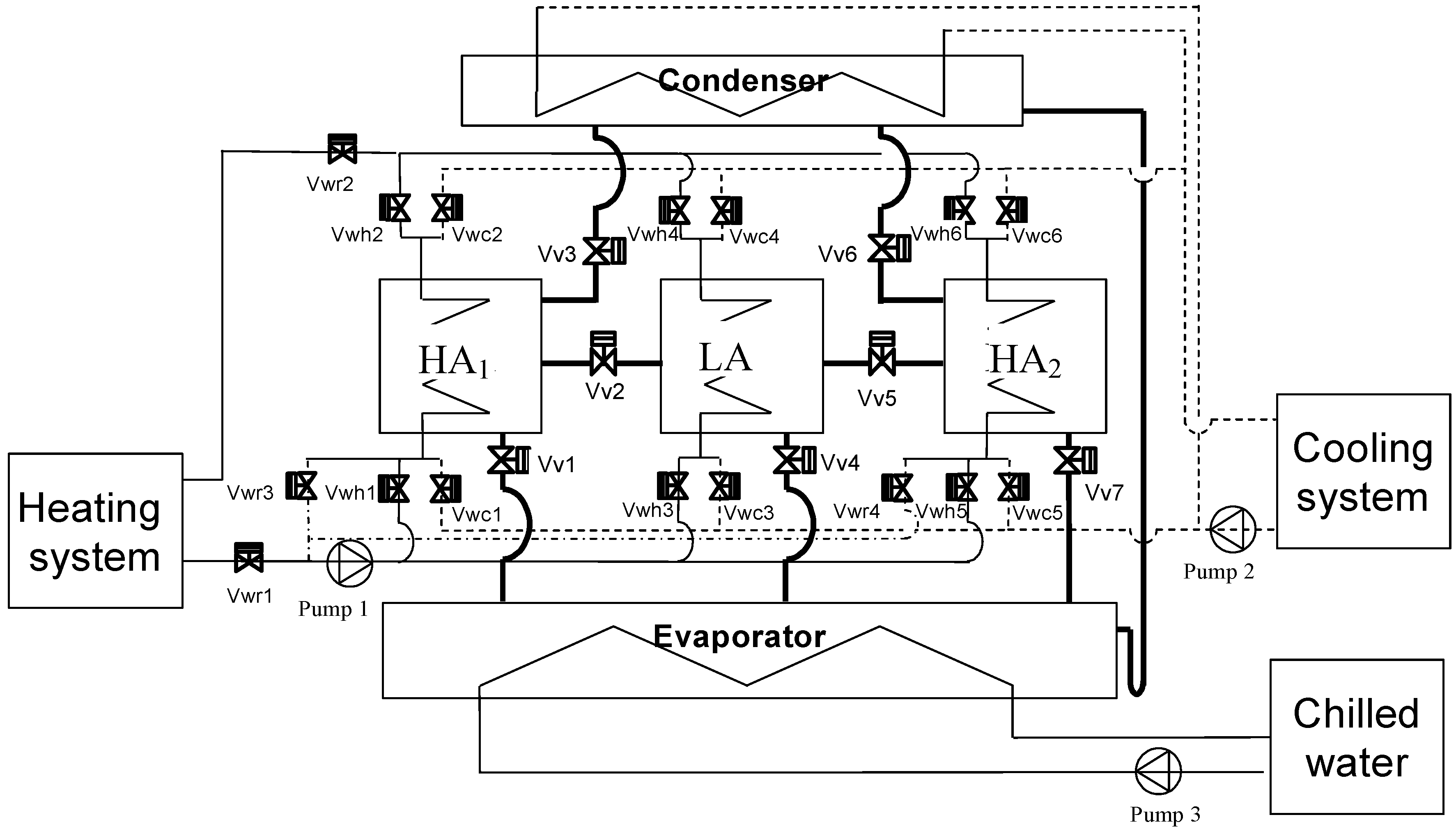
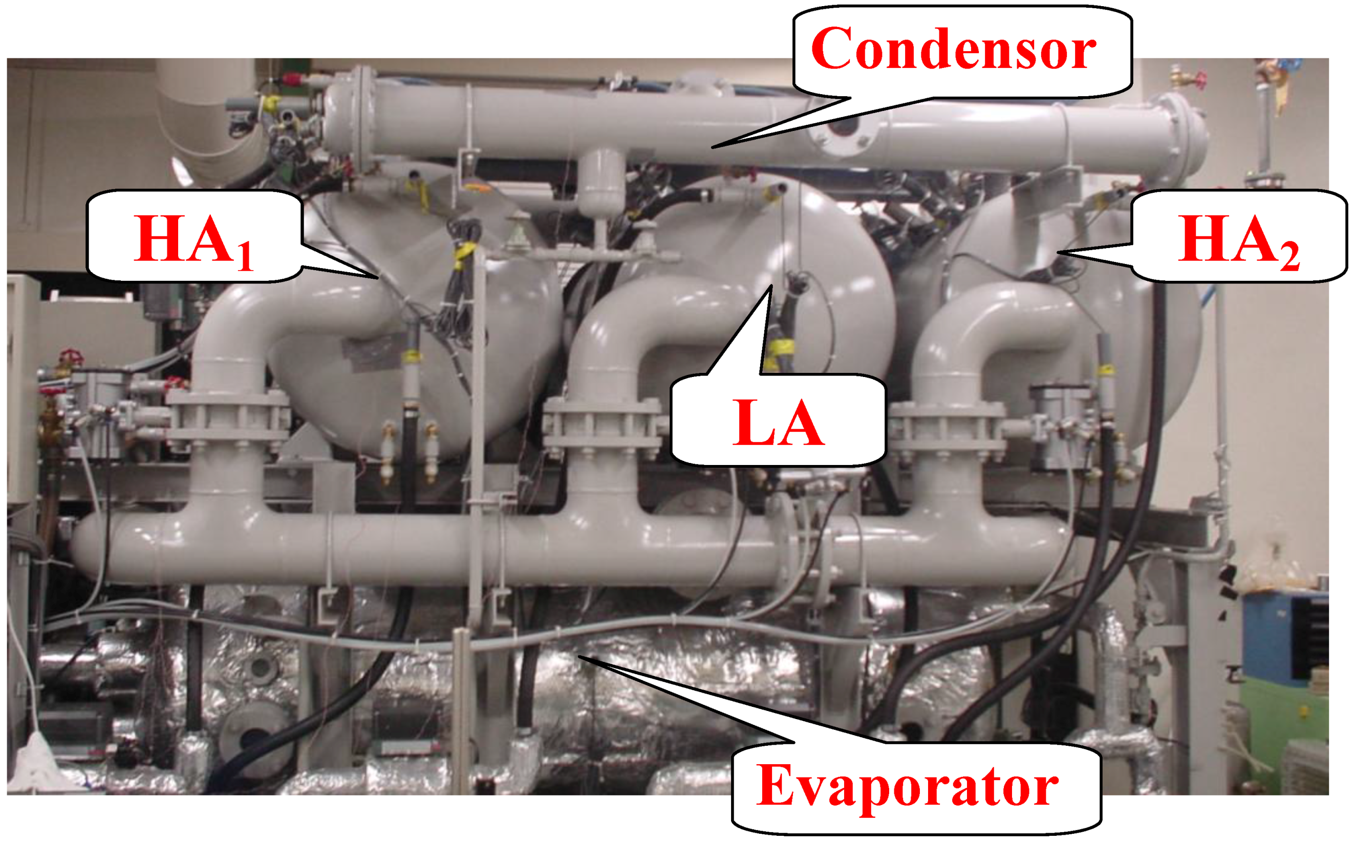
The adsorption cycle consists of a three-bed adsorber containing silica gel, namely high adsorber 1 (HA
1), high adsorber 2 (HA
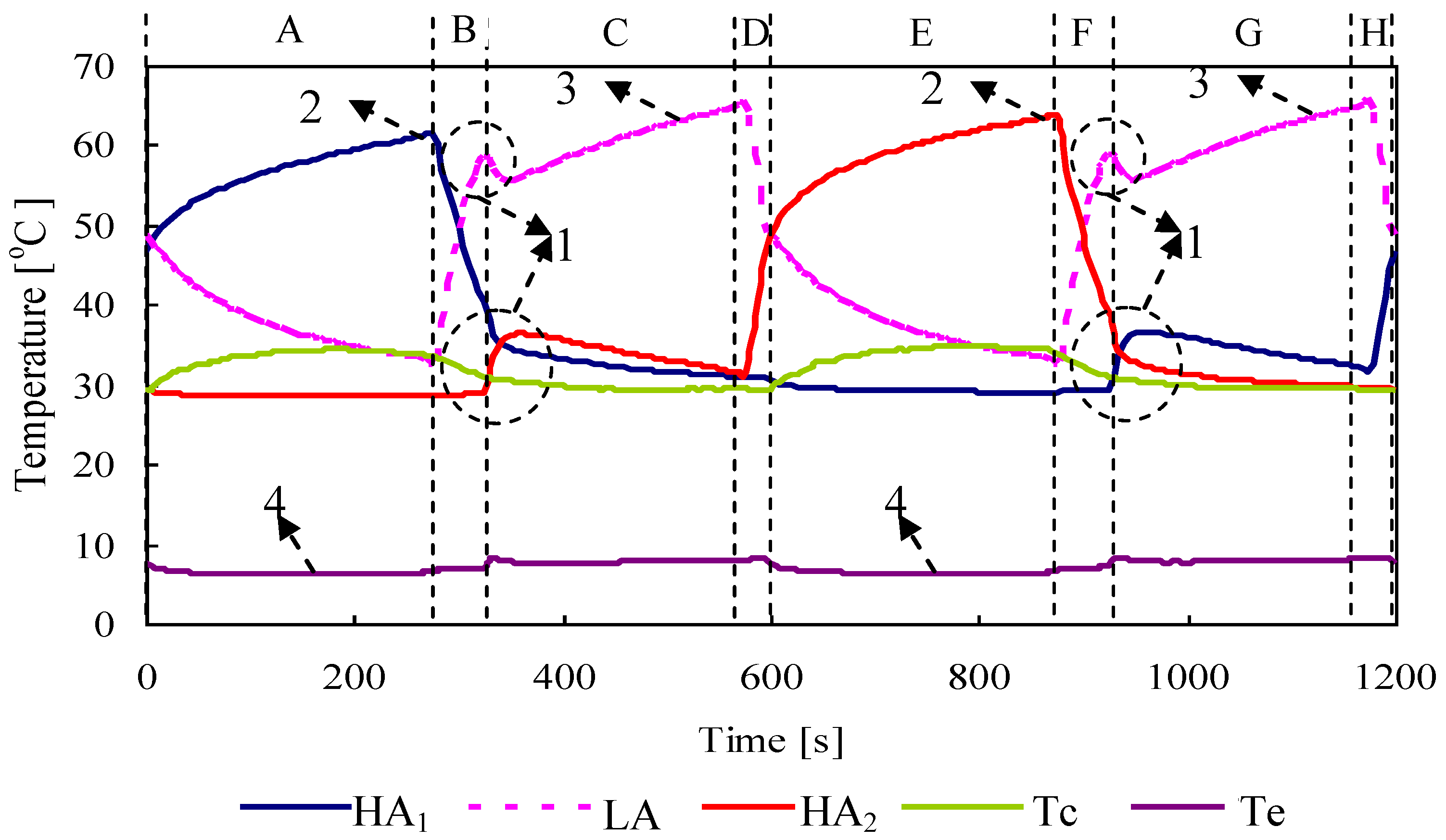
2) and low adsorber (LA). The processes in the cycle can be divided into eight modes. The processes that occur in each adsorbent can be explained as follows (
Table 1a). In mode A, HA
1 is in the heating process, while LA and HA
2 are in the cooling process. The heating system provides heat to HA
1 for the desorption process. This process provides sufficient energy for releasing the refrigerant from adsorbent pores, and the refrigerant then vaporizes to the condenser. By opening valve Vv
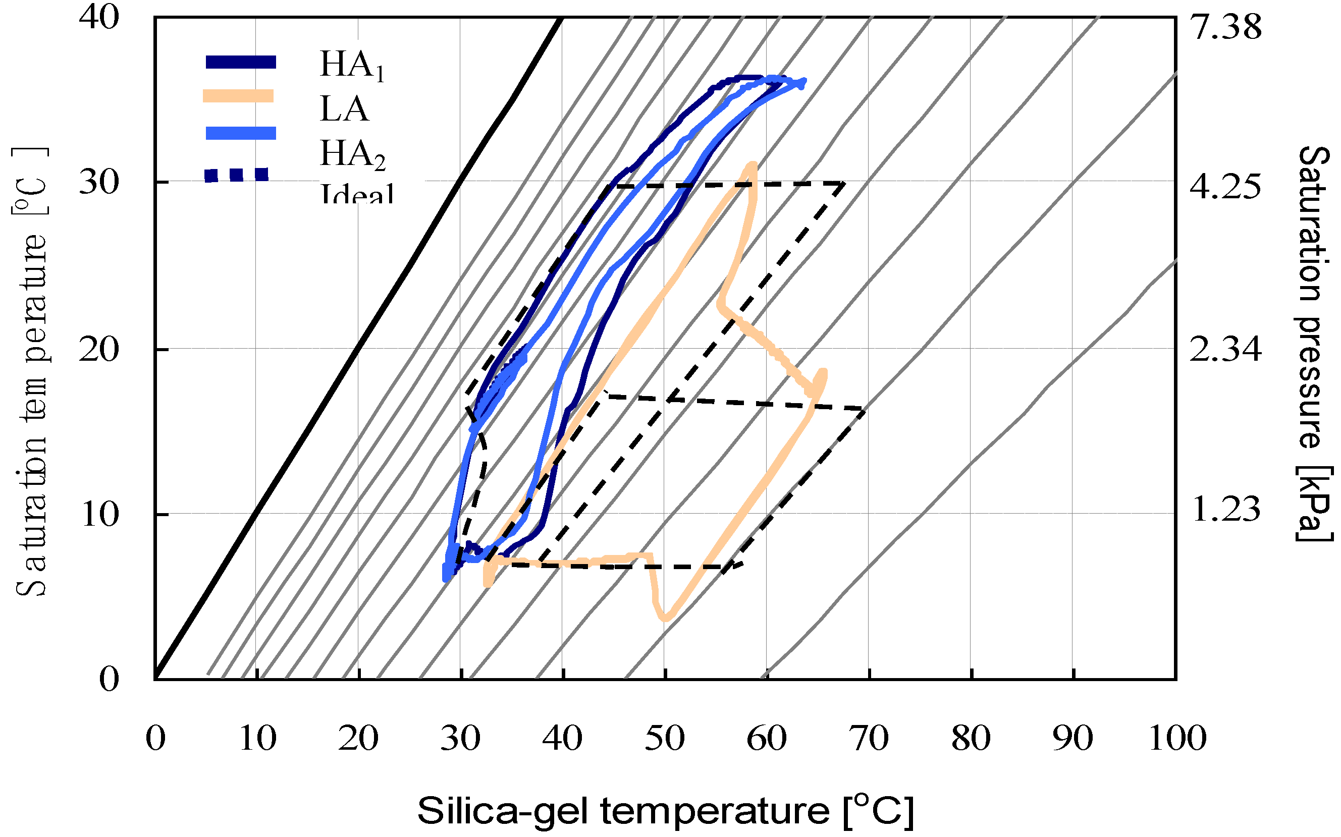
3 the refrigerant vapor will flow to the condenser. In the desorption process, the resulting refrigerant is cooled down in the condenser by circulating cooling water from the cooling system, which removes condensation heat. The desorption-condensation process occurs at condenser pressure (P
cond), as shown in
Figure 2, path 1–2. After the condensation process, liquid refrigerant flows to the evaporator. The evaporator is connected to HA
2 and LA by opening valves Vv7 and Vv4, respectively. In the adsorption-evaporation process, the refrigerant in the evaporator is evaported at a low temperature (T
eva) and captures heat (Q
eva) from chilled water. The evaporated vapor is adsorbed by HA
2 and LA. The cooling system also supplies cooling water to HA
2 and LA to remove adsorption heat released during the adsorption process. The adsorption-evaporation process occurs at evaporation pressure (P
eva). The process can be seen in
Figure 2 at paths 3–4 and 9–6 for HA
2 and LA, respectively.
In mode B, HA
2 continues the adsorption-evaporation process by remaining connected to the evaporator as described in mode A. Meanwhile, HA
1 and LA are now involved in the pre-cooling and pre-heating processes, respectively. HA
1 and LA are isolated from the other heat exchanger by closing valves Vv1, Vv2, Vv3, Vv4 and Vv5. As can be seen in
Figure 2, at the end of the desorption process (mode A), the pressure of HA
1 is at the high condenser pressure. Therefore, to switch the stage from desorption to the adsorption process, the pressure of HA
1 should be reduced to the evaporator pressure, which can be done by reducing temperature. The cooling water from the cooling tower is flowed to HA
1. Consequently, the temperature as well as the pressure of HA
1 decreases from point 2 to point 3. In contrast to HA
1, in mode B, the LA is in the pre-heating process (6–7). The objective of this process is to increase the pressure of LA before the mass recovery process begins in mode C. The initial pressure difference between LA and HA
2 is required at the start of the mass recovery process to make it effective. During the mass recovery process, LA is still in the heating process to achieve additional force for releasing the refrigerant. At the same time, HA
2 continues the cooling process. In other words, LA and HA
2 are in mass recovery while undergoing heating and cooling processes, respectively. The processes can be seen in
Figure 2, path 7–8 and path 4–5 for LA and HA
2, respectively. Concurrently, the cooling process occurs at HA
2 for effectively adsorbing refrigerant vapor.
Table 1.
Chiller heat exchanger state.
Table 1.
Chiller heat exchanger state.
In mode C, HA1 acts as an adsorber and is connected to the evaporator to start the mode. The process is identical to the adsorption-evaporation process that occurs in HA2 (mode A). In mode D, LA and HA2 are in pre-cooling (8–9) and pre-heating processes (5–1), respectively. In this mode, LA is cooled by cooling water and HA2 is heated by hot water. This mode is the initial condition for LA and HA2 before the adsorption and desorption process begin in mode E. In modes E–H, the process occurring in LA is similar to the corresponding process modes A–D. The difference is that HA1 and HA2 are in interchanged positions. For instance, in mode E, LA is in the same process, adsorption, as in mode A. However, the positions of HA1 and HA2 are reversed from mode A.
Figure 1.
Schematic diagram of three-bed adsorption refrigeration cycle.
Figure 1.
Schematic diagram of three-bed adsorption refrigeration cycle.
Figure 2.
Theoretical of the proposed cycle on P-T-X diagram.
Figure 2.
Theoretical of the proposed cycle on P-T-X diagram.
The working principle of the conventional single stage is presented in
Table 1b. The conventional single stage cycle requires at least two-bed adsorber to obtain a continuous refrigeration cycle. Since the performance of the cycles is influenced by the total mass of adsorbers, the total absorber should be identical for both the single stage and the proposed cycle. In the present study, the LA and HA
2 combine into one bed and perform the same mode. It can be seen in the table that mode A of the single stage cycle is similar to modes A and E of the proposed cycle, where one bed of HA performs the desorption process while another bed of combined HA and LA performs the adsorption process. Further explanation of the cycle and allocation time in each mode is shown in the
Table 1.


