Abstract
A new type of brushless double rotor machine (BDRM) is proposed in this paper. The BDRM is an important component in compound-structure permanent-magnet synchronous machine (CS-PMSM) systems, which are promising for power-split hybrid electric vehicle (HEV) applications. The BDRM can realize the speed adjustment between claw-pole rotor and permanent-magnet rotor without brushes and slip rings. The structural characteristics of the BDRM are described and its magnetic circuit model is built. Reactance parameters of the BDRM are deduced by an analytical method. It is found that the size characteristics of the BDRM are different from those of conventional machines. The new sizing and torque equations are analyzed and the theoretical results are used in the optimization process. Studies of the analytical magnetic circuit and finite element method (FEM) model show that the BDRM tends to have high leakage flux and low power factor, and then the method to obtain high power factor is discussed. Furthermore, a practical methodology of the BDRM design is developed, which includes an analytical tool, 2D field calculation and performance evaluation by 3D field calculation. Finally, different topologies of the BDRM are compared and an optimum prototype is designed.
1. Introduction
The power-split hybrid drive system which employs the planetary gear and two electric machines is the most advanced and successful electric drive system among hybrid systems at present. It integrates the advantages of the parallel and series hybrid drive systems. Another power-split hybrid system which is called compound-structure permanent-magnet synchronous machine (CS-PMSM) system in this paper represents a new development direction in the field of hybrid systems [1,2,3,4]. It employs a generator and a motor to adjust the torque and speed difference between the engine and the load, providing the function of the continuously variable transmission (CVT). One topology of the CS-PMSM is shown in Figure 1.
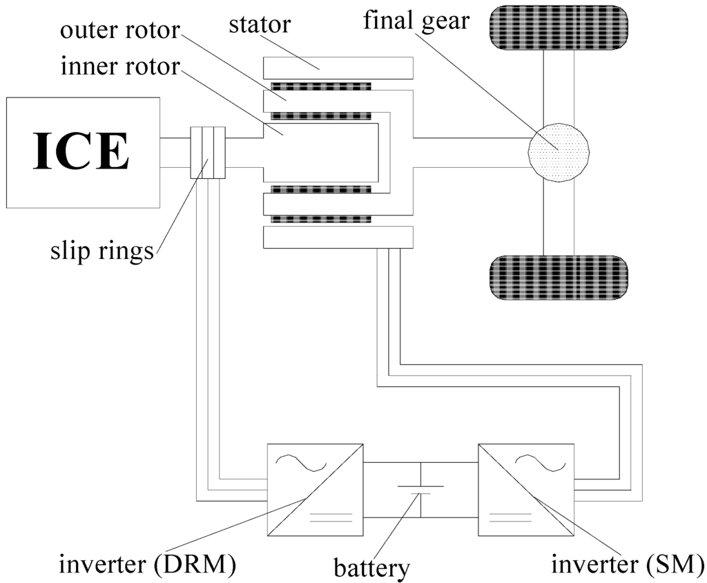
Figure 1.
CS-PMSM system.
Compared with planetary gear unit, the CS-PMSM is a competitive concept for hybrid electric vehicle (HEV) drivetrain due to its compact structure and high efficiency [5,6,7]. But it has a significant disadvantage: the rotating windings need brushes and slip rings. This may cause problems such as friction losses, maintenance, cooling and so on [8].
To solve this problem, a novel brushless double rotor machine (BDRM) is proposed in this paper. The BDRM is an important component in the new brushless CS-PMSM system, which is shown in Figure 2. In the brushless CS-PMSM system, the permanent-magnet rotor 1 is connected to the internal combustion engine (ICE), and the claw-pole rotor is connected to the load. Since the claw-pole rotor and permanent-magnet rotor 1 can operate at different speeds, the ICE can operate at the optimum speed independent of the load. BDRM transfers the ICE torque directly to the load, and conventional machine (CM) adds/subtracts additional torque to/from the load and in this way the output torque demand is always satisfied independent of ICE operation.
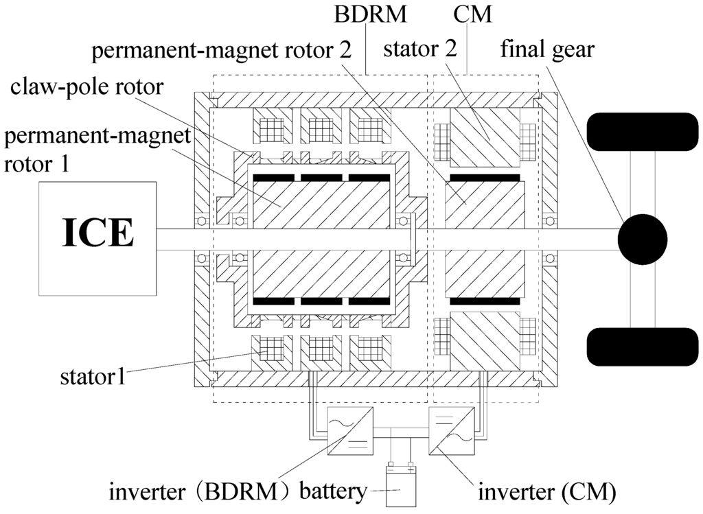
Figure 2.
Brushless CS-PMSM system.
The power flow path in the brushless CS-PMSM system is shown in Figure 3. Five typical operation states of the power-split hybrid drive system are shown in Figure 4. In pure electric mode, the vehicle wheels are simply driven by the CM, as shown in Figure 4(a). In ICE starter mode, only the BDRM works and the power flow is illustrated in Figure 4(b). In CVT mode, the electricity generated by the BDRM supplies the CM, the torque and speed of the ICE are changed to meet the torque and speed required at the wheels, as illustrated in Figure 4(c). When the power required at the wheels is higher than the power input from the ICE, the battery will provide the rest power through the brushless CS-PMSM, as shown in Figure 4(d). The CM can also work as a generator to recover the brake energy and the power flow is shown in Figure 4(e).
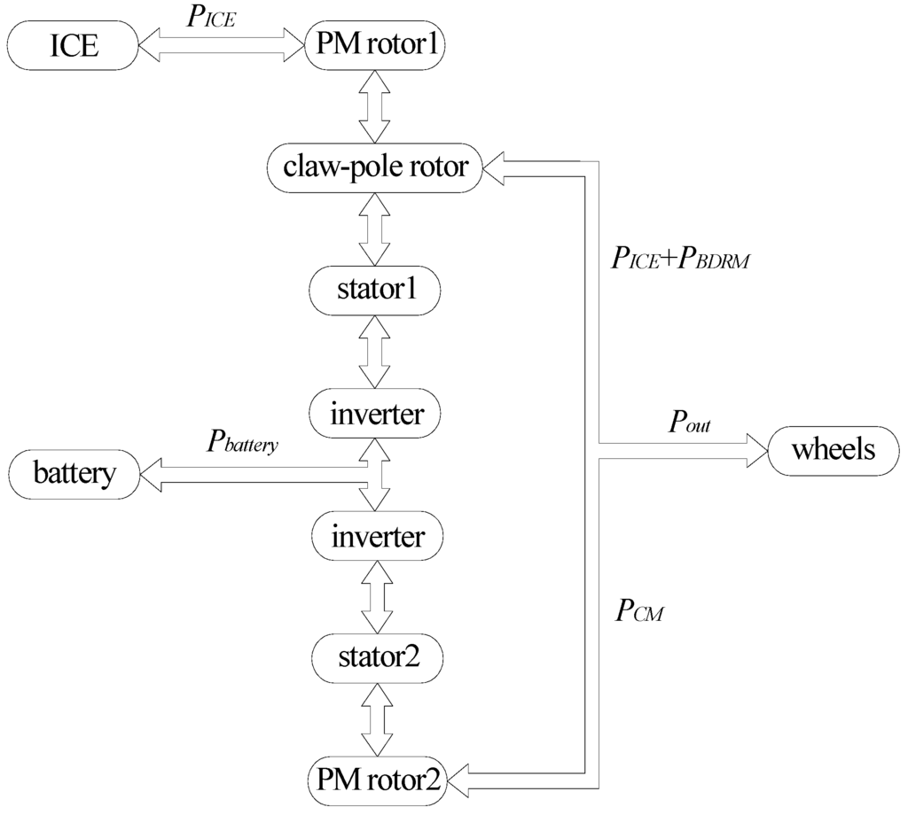
Figure 3.
Power flow path in the brushless CS-PMSM system.
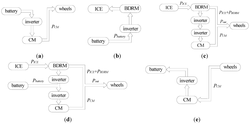
Figure 4.
Typical operation states of the power-split hybrid drive system: (a) Pure electric mode; (b) ICE starter mode; (c) CVT mode; (d) Acceleration and hill climbing mode; (e) Braking mode.
The relationship between the speed of the claw-pole rotor and permanent-magnet rotor 1, angular frequency of the stator 1 windings is shown in (1):
where Ωc is the mechanical speed of the claw-pole rotor (rad/s); Ωp is the mechanical speed of the permanent-magnet rotor 1 (rad/s); ωs the angular frequency of the stator winding current (rad/s); p is the pole-pair number of the BDRM.
The output torque of the shaft comprises the torque of the BDRM and the torque of the CM:
where TCM is the torque of the CM, which can be positive and negative, depending on the torque difference between the ICE and output demand, and ΤBDRM is the torque of the BDRM.
Without considering various losses of the two machines, the output mechanical power is:
where PICE is the input mechanical power of the ICE, Ρbattery is the input power of the battery, PCM is the electromagnetic power of the CM and PBDRM is the electromagnetic power of the BDRM.
The whole brushless CS-PMSM system employs the BDRM and the CM to adjust the speed and torque difference between the ICE and the load. The removal of mechanical planetary gear and brushes greatly reduces both mechanical cogging noise and maintenance cost of the power-split HEV system. Besides, the proposed BDRM has several other features especially interesting for HEVs: (1) as the stator coil is close to the motor case, the windings can be cooled by conventional methods and the BDRM is expected to have better thermal performance which is a significant advantage for vehicle applications; (2) there are no end windings in the BDRM, the slot shapes and dimensions of the stator have high design freedom and the slot fill factor can be extremely high, so the copper loss is low and the vehicle space can be effectively used; (3) the stator windings and stator cores are simple and easy to manufacture, which helps reduce the cost of HEVs. All the above advantages make the BDRM promising for power-split HEV applications.
2. Basic Topology and Magnetic Circuit Model of the BDRM
The BDRM is a new type of 3-phase claw-pole machine with two air gaps and is composed of three parts: stator 1, claw-pole rotor and permanent-magnet rotor 1. Claw-pole rotor is located between the stator 1 and the permanent-magnet rotor 1. There is an outer air gap between claw-pole rotor and stator 1, and an inner air gap between claw-pole rotor and permanent-magnet rotor 1.
The circular magnetic field formed by stator 1 is modulated by the claw-pole rotor and is distributed in the circumferential direction. In this way, it is possible to drag the permanent-magnet rotor 1 to rotate at its synchronous speed and to change the speed difference between the claw-pole rotor and permanent-magnet rotor 1.
Figure 5 shows the flux path for one pole of the BDRM, where the arrow stands for the flux direction. The d- and q-axis equivalent magnetic circuits with load are shown in Figure 6. In Figure 6, symbol R represents the reluctance, symbol F represents the magnetomotive force (MMF) and their subscript symbols are explained by the remark of Figure 6 on the right. It can be seen from Figure 5 and Figure 6 that the flux in BDRM is distributed in three dimensions, which makes its analysis and modeling more complicated.
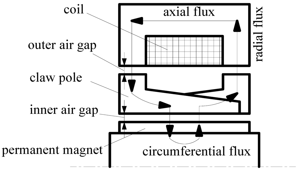
Figure 5.
Flux path in one pole of the BDRM.
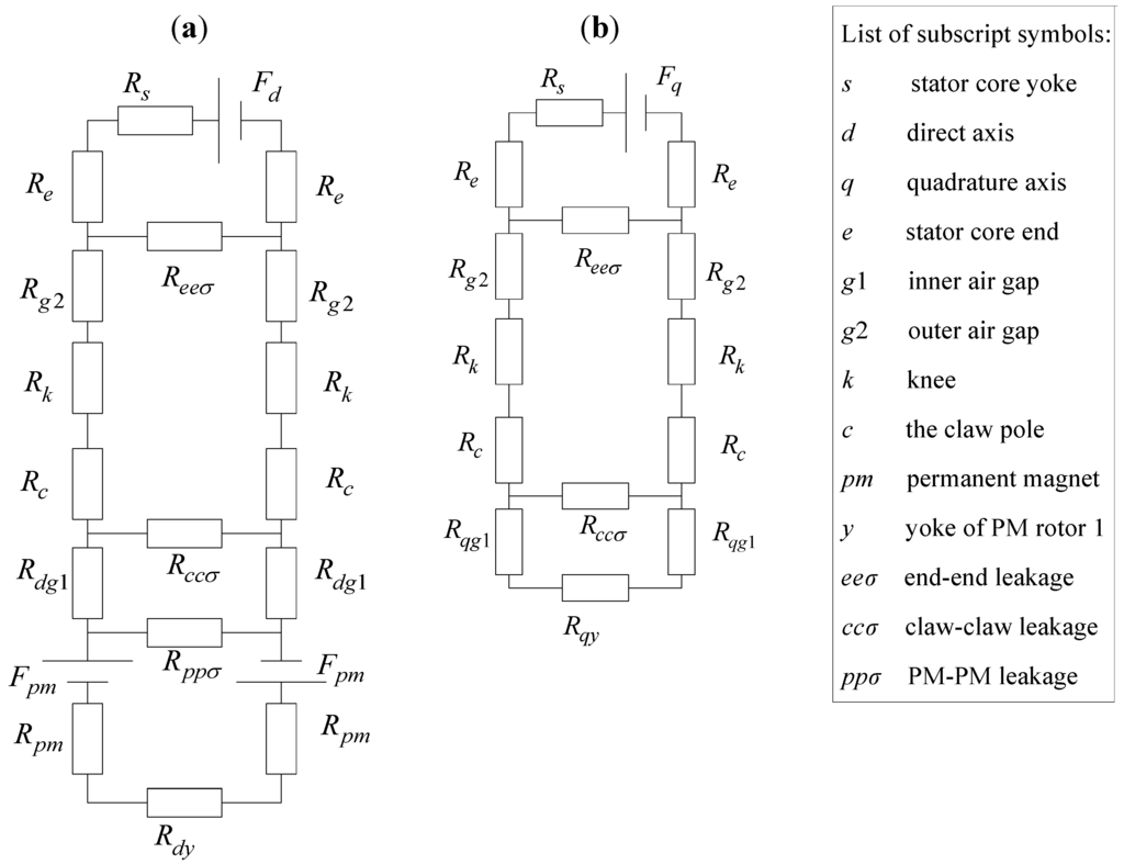
Figure 6.
Equivalent magnetic circuit diagrams with load: (a) d-axis; (b) q-axis.
3. Reactance Parameters of the BDRM
Compared with traditional PMSMs, the BDRM has a different winding form, one more air gap and more complex leakage flux paths. It is therefore pertinent to analyze the new parameter characteristics. In order to simplify analysis, considering the non-salient pole situation, the reactance of d-axis is the same with that of q-axis. With the help of the q-axis equivalent magnetic circuit shown in Figure 6(b), reactance parameters can be deduced. The leakage inductance between the stator core ends is calculated by:
where , p is the pole-pair number, N is the number of stator-coil turns, I is its current value, Φeeσ is the leakage flux passing through Reeσ.
The leakage inductance between the claws can be calculated by:
where Φccσ is the leakage flux passing through Rccσ.
Thus, the leakage reactance of the armature winding per phase can be calculated by:
where f is the frequency of the current.
The armature reaction reactance of the winding per phase is calculated by:
where Φa is the main flux passing through Rqg1.
The reluctance of ferromagnetic materials is not a constant but changes with the flux density. For approximate calculation, it can be assumed that the permeability of ferromagnetic materials . Then the magnetic circuit can be simplified as shown in Figure 7 and the simplified reactance expressions can be obtained as in Equations (8)–(11).
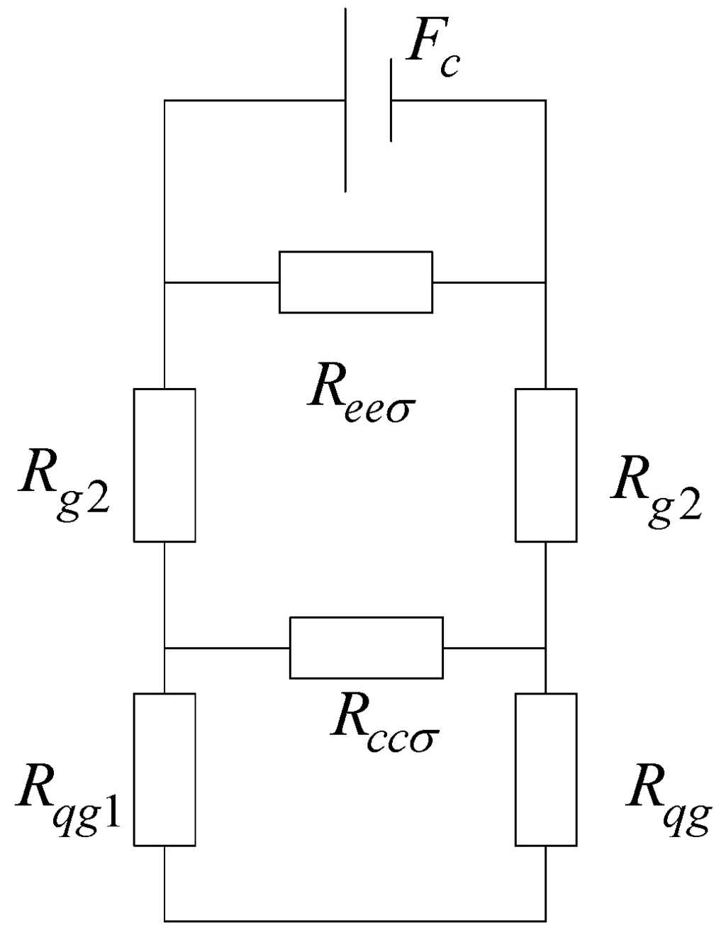
Figure 7.
Simplified magnetic circuit.
4. Sizing and Torque Equations of the BDRM
The stator windings are embedded in the inner surface of stator 1, so the general definition of electric load can not properly reflect the real status in BDRM. A new definition of electric loading is given as the current sum per axial armature length:
where lef is the effective axial length of single-phase BDRM.
The new sizing and torque equations of the BDRM is derived as:
where P’ is the output apparent power, D1 is the inner diameter of the claw-pole rotor, n is the synchronous speed, m is the phase number, Kw is the winding factor, αp’ is the effective pole arc coefficient, Bδ1 is the maximum flux density in the inner air gap, σ1 is the leakage factor of the flux from the inner air gap into the outer air gap, σ2 is the leakage factor of the flux from the outer air gap into the stator core.
It can be seen from Equations (13) and (14) that the sizing and torque equations of the BDRM are different from those of traditional PMSMs. When the motor constant CA remains unchanged, the output apparent power P’ is proportional to the inner diameter of the claw-pole rotor D1, the pole-pair number p, the synchronous speed n, and the square of the motor axial length lef. Special size characteristics of the BDRM can be drawn from analysis of Equations (13) and (14):
Theoretically, simply increasing the pole-pair number p can increase the output power. The output power is proportional to the square of the motor axial length lef, which means that a larger lef can lead to a higher power density. Appropriate reduction of the inner diameter of the claw-pole rotor D1 can increase the power density. The MMF of the winding per phase is proportional to the number of turns per phase and the changes of the pole-pair number p will not affect the MMF.
5. Power Factor Analysis of the BDRM
Results from analytical and finite element method (FEM) calculation show that the power factor of BDRM, about 0.5~0.75, is low. This results from the special configuration of BDRM, which brings about a serious leakage flux in the magnetic circuit.
The relation of all electromagnetism parameters of BDRM can be denoted in electric performance by the phasor diagram of the synchronous motor. Figure 8 shows the phasor diagram of the BDRM when Id = 0, where E0 and Eδ are the fundamental back electromotive forces (BEMFs) at no-load and load operations, Id, Iq are the d- and q-axis armature currents, R1 is the armature resistance, U is the voltage fed by external circuit, Lq is the q-axis inductance, ω is the radian frequency, θ is the torque angle and φ is the power factor angle.
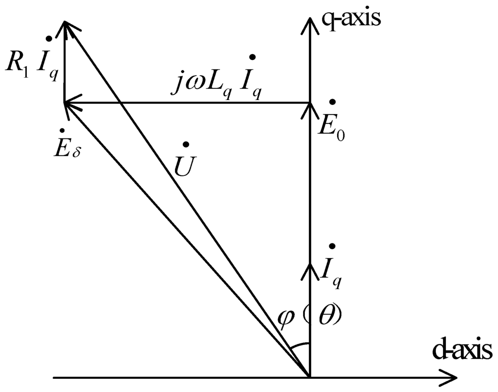
Figure 8.
Phasor diagram when Id = 0.
Neglecting the small voltage drop across phase resistance, the power factor could be expressed as:
and if unsaturated:
where Φi is the flux induced by armature current only, Φm is the flux induced by permanent magnets only.
This equation could be further transformed to:
Equations (16) and (17) present the basic factors affecting the power factor. By decreasing the armature current while Φm is fixed, the power factor will be enhanced and the torque density of BDRM will fall at the same time. By reducing the pole number of BDRM when the leakage flux between the claws is reduced, the power factor is slightly enhanced. For both methods, a compromise between the torque density and the power factor must be made. Another effective way to improve the power factor and enhance torque density at the same time is to simply enhance Φm, but more permanent magnets increase the cost of the machine, and this is clearly not attractive in practice, so in order to obtain the best performance, a compromise among all parameters should be made.
It is of course possible to alter the timing of the position sensors which control inverter switching so as to change the phase of the current I relative to E0. This raises the question whether such timing adjustment could be used to improve power factor in BDRM.
It can be assumed that ψ is the leading angle of I to E0, Id = I∙sinψ, Iq = I∙cosψ, then the power factor could be expressed as:
where Xd, Xq are the d- and q-axis synchronous reactance.
In the instance that the magnitude of I remains unchanged, after putting FEM results of E0, Xd, Xq into Equation (18), variation of power factor with respect to is shown in Figure 9.
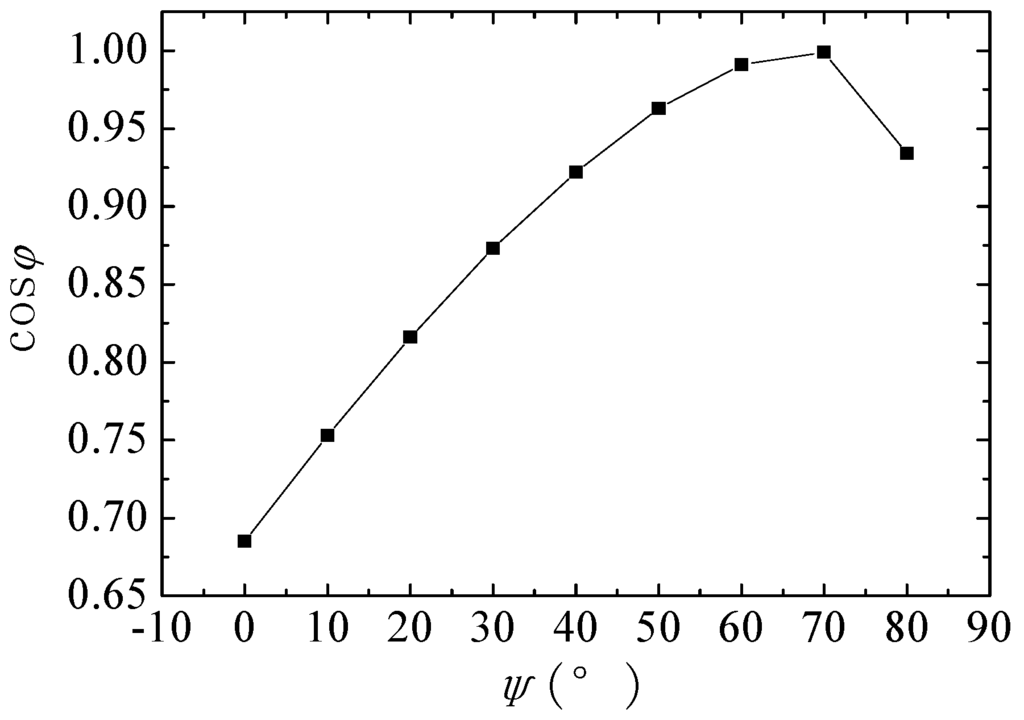
Figure 9.
Power factor versus .
As shown in Figure 9, a higher power factor is achieved with a greater d-axis current. However, to achieve a maximum torque for given current, the current I must be in phase with E0, and a greater d-axis current means that sacrifice of torque is inevitable. The compromise between the torque density and the power factor must also be made.
6. Practical Design Methodology
6.1. Performance Evaluation by 3D Field Calculation
The magnetic flux in BDRM flows in three dimensions. 3D FEM is used to validate the solution, taking into account the inherent 3D effects of the BDRM. Because of the symmetry of the structure and the almost independent magnetic circuits between the three stacks, only one pole-pair of a phase is required for the FEM of the magnetic field, as is shown in Figure 10.
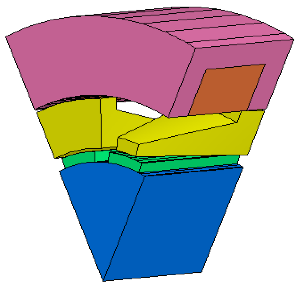
Figure 10.
3D BDRM model.
Figure 11 shows the flux-linkage and BEMF waveforms of one-phase BDRM at no load. Figure 12 shows the FEM calculated torque curve of the BDRM at rated load. And the maximum torque ripple is acceptable in the vehicle traction application.
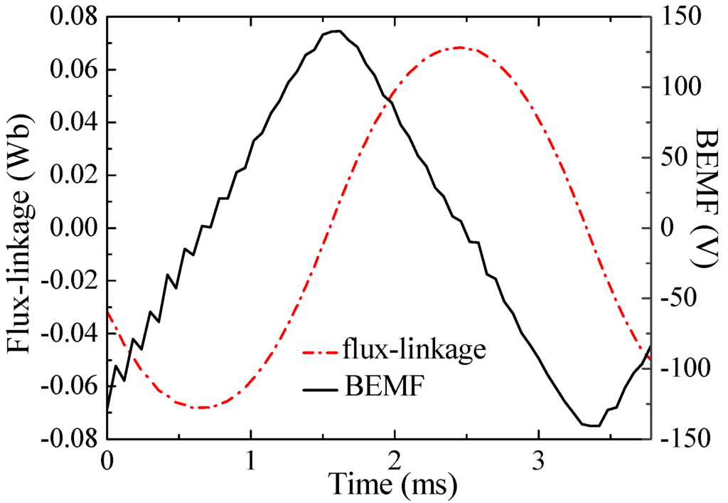
Figure 11.
The flux-linkage and BEMF in one-phase at no-load.
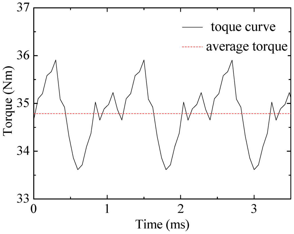
Figure 12.
FEM calculated torque curve of the BDRM.
6.2. Determination of the 2D Equivalent Structure
3D FEM can be directly used to simulate the operation and to evaluate the performance of a given motor structure [9,10]. However, it is not efficient to use the 3D field calculation for initial design and determination of the optimal geometrical dimensions, because it requires much computation time and memory, and it is hard to model claw-poles [11,12]. Such assistance can be achieved with a 2D field calculation tool.
The use of a 2D field calculation tool to simulate the 3D structure also needs another level of simplification hypotheses [13,14]. The magnetic paths of the 2D equivalent model are designed to have the similar magnetic resistance in each corresponding part with 3D model. Figure 13 shows the corresponding 2D equivalent model. Inner air gap flux density and BEMF from 2D and 3D FEM are compared in Figure 14 and Figure 15 respectively. In Table 1, modeling and computation time for 2D and 3D analysis for BDRM are also compared.
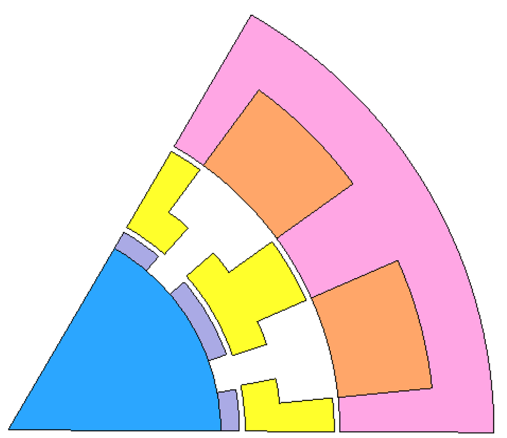
Figure 13.
The 2D equivalent model.
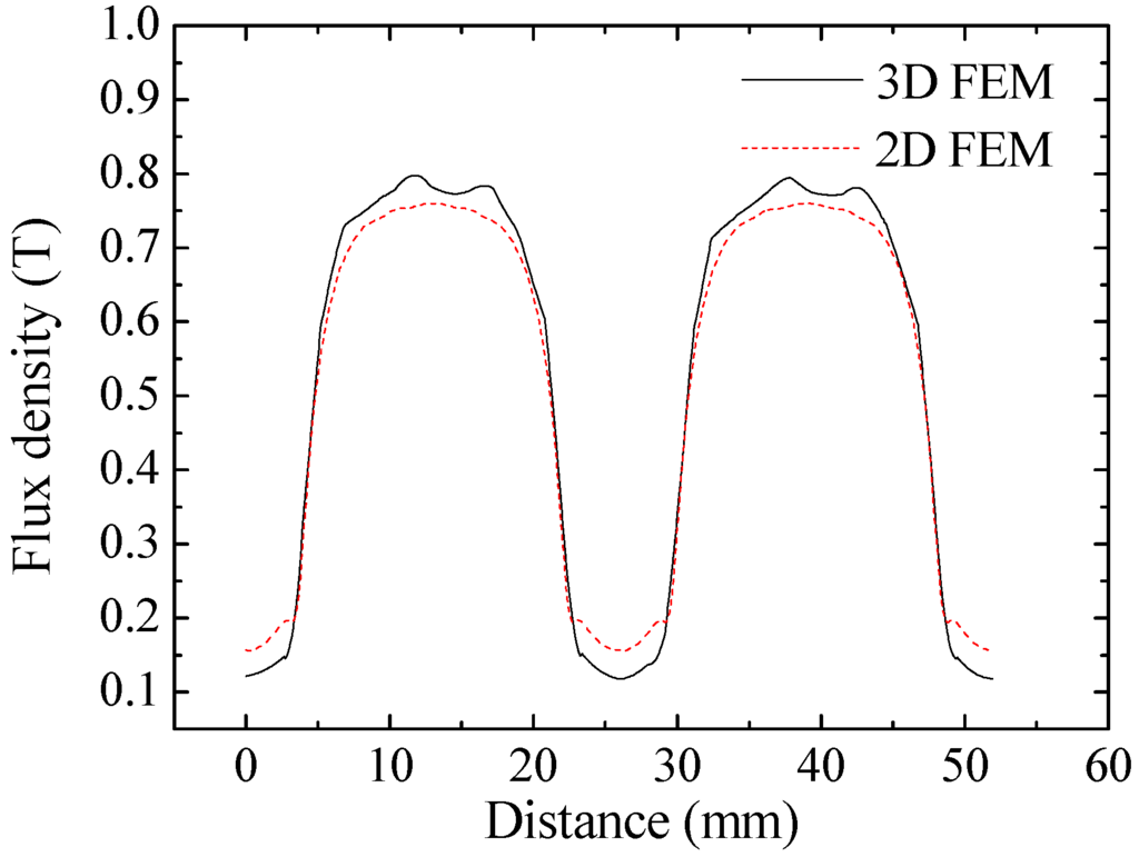
Figure 14.
Inner air gap flux density from 2D and 3D FEM.
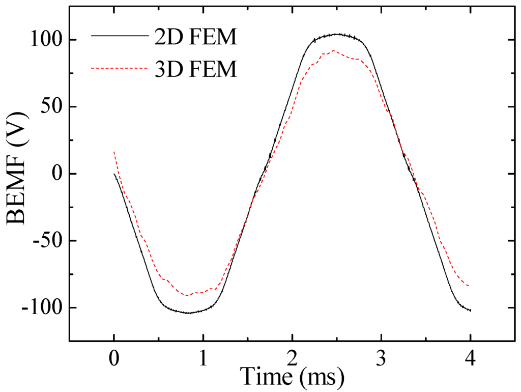
Figure 15.
BEMF from 2D and 3D FEM.

Table 1.
Comparison of 2D FEM and 3D FEM.
| Number of elements | Computation time for magnetostatic field | Computation time for transient field | System | |
|---|---|---|---|---|
| 2D FEM | 9254 | 19 s | 6 min/3 s | 2.31 GHz AMD Phenom with 2.75 GB RAM |
| 3D FEM | 125392 | 7 min/37 s | 5 h/59 min/35 s |
From the comparison it is shown that the flux density from 2D and that from 3D FEM agrees well, but the BEMF waveform from 2D FEM is a little higher than the 3D FEM result. The difference is caused by the simplified shape of the claws. Leakage flux from the tip and top surface of the claws to adjacent claws is not reflected in the 2D FEM model, which makes BEMF from 2D simulation a little higher than the 3D simulation result. To validate the applicability of the simplification method, the simulated performance of BRDM is compared between 3D and the corresponding 2D equivalent models considering the sensitivity of geometric parameters. No-load BEMF and average load torque versus the thickness of stator core, pole arc coefficients of the claw tip, and axial length of single phase are calculated by both 2D FEM and 3D FEM, as shown in Figure 16.

Figure 16.
No-load BEMF and average torque from 2D FEM and 3D FEM: (a) Models with different pole arc coefficients of the claw tip; (b) Models with different axial lengths of single-phase; (c) Models with different thickness of stator cores.
Compared with the 3D FEM, similar simulation results are reached by 2D FEM under various geometric parameter changes, which proves the feasibility of the simplified method. Although there is still a little deviation caused by simplification of the flux leakage paths, the 2D equivalent model is well adapted to an iterative optimization procedure for the optimal design of machine dimensions.
6.3. Flowchart of the Design Methodology
The design of the BDRM is complicated due to its 3D structure with more complex flux paths and more geometrical variables than those of conventional 2D structures, so an efficient design methodology covering an analytical tool, 2D field calculation and performance evaluation by 3D field calculation is illustrated by the flowchart of Figure 17.
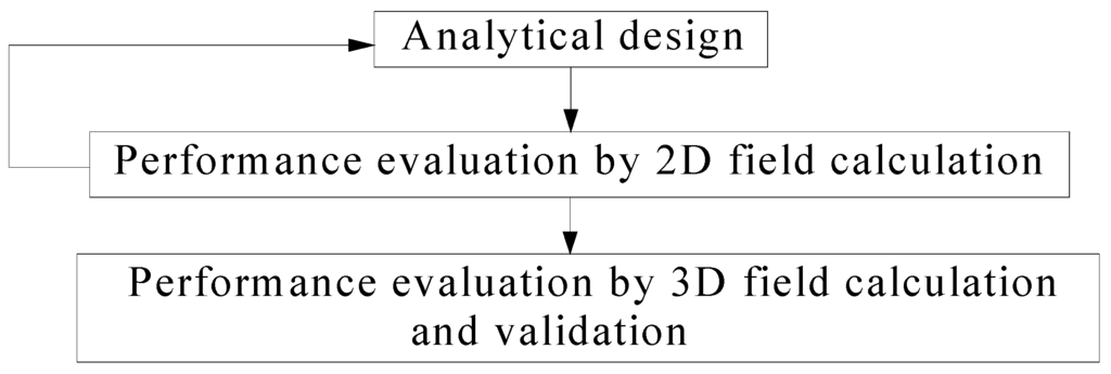
Figure 17.
Flowchart of the design methodology.
3D FEM possesses definite advantages for the sufficient accuracy and is used preferably in the last step of the iterative design process to evaluate the performance of a given motor structure, but the interactive use of the analytical tool and 2D field calculation tool better simplifies the optimization process, and is therefore advantageous for the initial design. With simple modeling and much less computation time, the proposed analysis method can be directly applied to the analysis and design of the BDRM.
7. Optimization of the BDRM
7.1. Pole-Pair Number
Unlike traditional PMSMs, the BEMF of stator winding of BDRM is relevant to the pole-pair number. Figure 18 is the variation curve of BEMF with the pole-pair number.
A high pole-pair number is required in order to increase the output power. However, the electrical frequency increases with pole-pair number which will incur excessive iron loss. Moreover, the leakage inductance will also be increased and it may result in a poor power factor. Considering the above situation, the pole-pair number is chosen as 6.
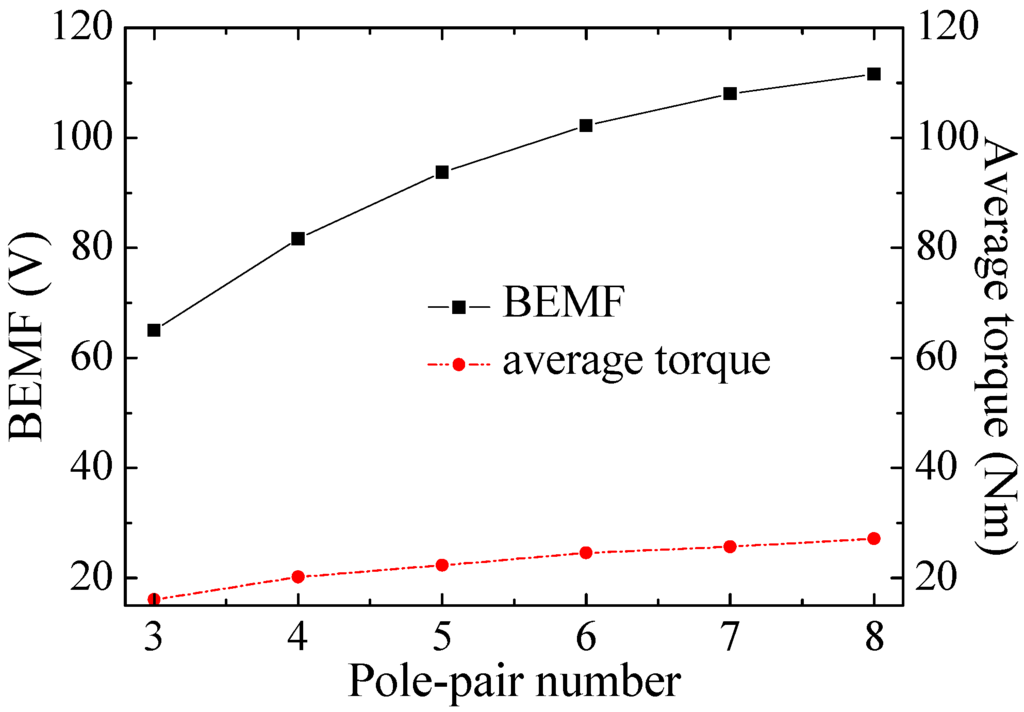
Figure 18.
Variation of BEMF and average torque with the pole-pair number.
7.2. Shape of the Claws
Optimization of the claw pole geometries is carried out to reduce the leakage flux between two adjacent claws. The most common shapes of the claws are rectangular, triangular and trapezoidal. Pervious analysis shows that the trapezoidal shaped claws structure has better performance [15]. Figure 19 and Figure 20 show the effects of the pole arc coefficient of the claw tip and claw root on torque ripple and average torque, respectively. Figure 21 shows the no-load flux density distribution on the surface of the appropriate claw at maximum linked flux after optimization. It can be seen that the flux density distributed around the claw is not saturated.
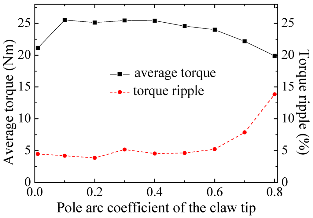
Figure 19.
Variation of average torque and torque ripple with pole arc coefficient of the claw tip.
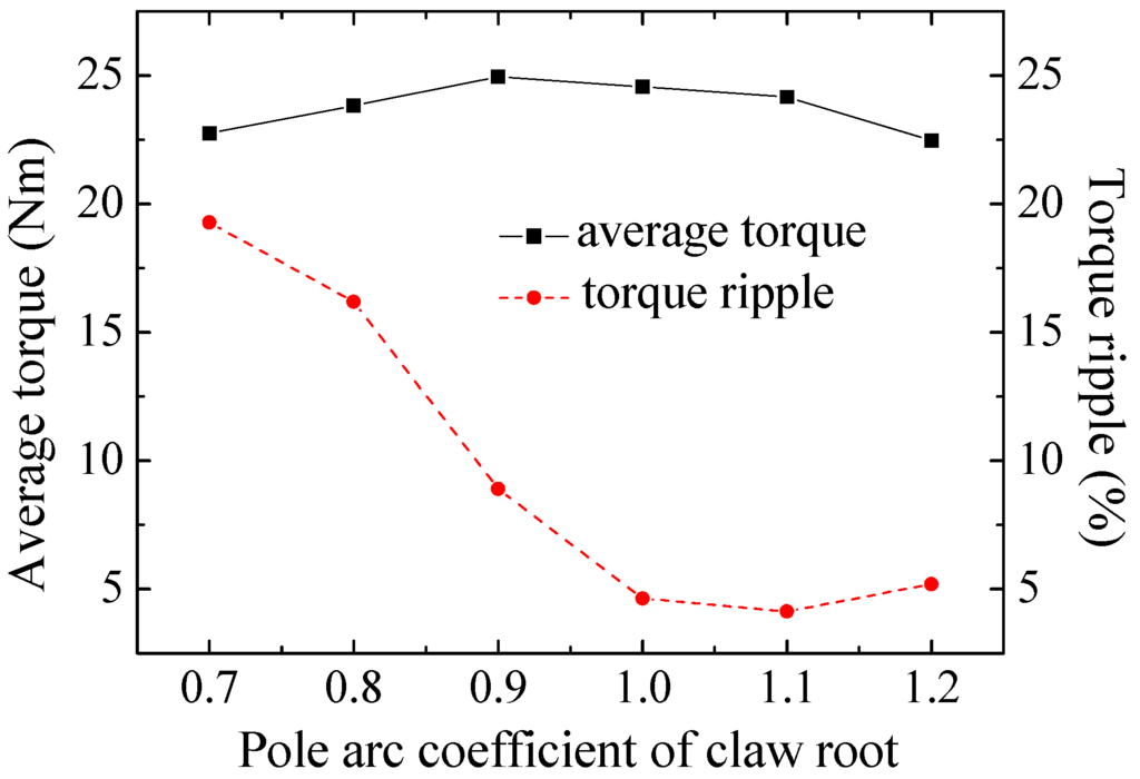
Figure 20.
Variation of average torque and torque ripple with pole arc coefficient of the claw root.
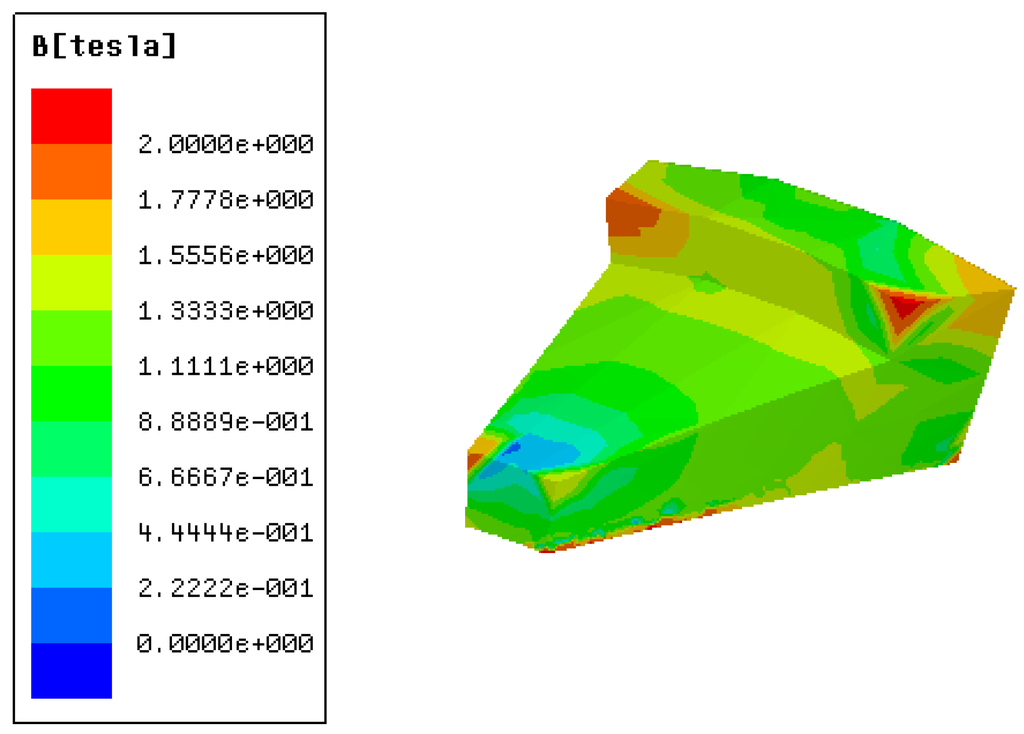
Figure 21.
No-load flux density distribution of the claw at maximum linked flux.
7.3. Permanent-Magnet Rotor Structure
Because the work environment of HEVs requires small volume, high power density and dependability, different permanent-magnet rotor structures are compared to find the most suitable type. According to the direction of the excitation of the permanent magnets, the rotor type can be divided into radial structures and tangential embedding structures. On the basis of the mount form of the permanent magnets, the rotor type can fall into surface-mounted and embedding. The effects of different permanent-magnet rotors on the performance of the BDRM are presented in Table 2.

Table 2.
Comparison between different permanent-magnet rotors.
| Types of permanent-magnet rotors | Radial surface-mounted | Radial embedding | Tangential embedding |
|---|---|---|---|
| Amplitude of fundamental BEMF (V) | 102.19 | 83.42 | 165.27 |
| THD of BEMF (%) | 5.60 | 18.31 | 18.84 |
| Peak-peak value of cogging torque (Nm) | 1.14 | 2.16 | 3.85 |
| Average torque (Nm) | 24.55 | 21.42 | 38.90 |
| Torque ripple (%) | 4.63 | 5.90 | 6.39 |
As can be seen from Table 2, the BDRM with radial surface-mounted rotor has the best BEMF waveform and the lowest torque ripple. Then the BDRM with tangential embedding rotor has the highest amplitude of fundamental BEMF and average torque. This phenomenon can be explained from the comparison of the inner air gap flux density waveforms in Figure 22. Different permanent-magnet rotors result in different amplitude and distribution of the air gap magnetic field, which will further influence the waveform of BEMF and then output torque. As more permanent magnets can be placed in a certain volume, the highest amplitude of air gap flux density is obtained in tangential embedding rotor. Considering the operational reliability and power density, this paper selects the tangential embedding type rotor, which is somewhat better in both regards.
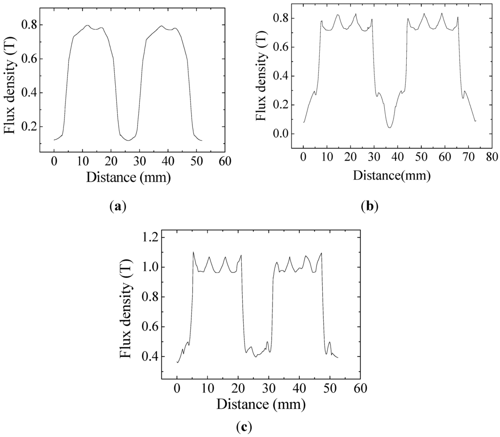
Figure 22.
Inner air gap flux density: (a) Radial surface-mounted structure; (b) Radial embedding structure; (c) Tangential embedding structure.
7.4. Optimized Prototype of the BDRM
A prototype of the BDRM machine has been designed and optimized. The parameters of the machine are listed in Table 3. The three phases of the BDRM are stacked axially with an angular shift of 120 electrical degrees from each other. In the future, this prototype will be made and the calculation results will be validated by experimental measurements.

Table 3.
Parameters of the BDRM.
| Parameters | Value |
|---|---|
| Rated power (kW) | 10 |
| Number of phase | 3 |
| Rated speed (rpm) | 2800 |
| Rated current (A) | 35 |
| Number of poles | 12 |
| Rated efficiency (%) | 89.8 |
| Rated power factor | 0.69 |
| Stator outer diameter (mm) | 189 |
| Shaft diameter (mm) | 48 |
| Axial length of BDRM (mm) | 126 |
| Outer air gap length (mm) | 0.7 |
| Inner air gap length (mm) | 0.7 |
| Winding turns in series per phase | 31 |
| Amplitude of fundamental no-load BEMF (V) | 140.81 |
| THD of BEMF (%) | 17.73 |
| Peak-peak value of cogging torque (Nm) | 3.46 |
8. Conclusions
To eliminate the undesired brushes and slip rings, a new type of BDRM is proposed in this paper, which is promising for power-split HEV applications. The structure as well as the operating principle of the proposed machine is introduced. The equivalent magnetic circuit and reactance formulas of the BDRM are built to construct a detailed understanding of the flux distribution. Its sizing and torque equations are developed to permit comparison of the size characteristics between the BDRM and traditional synchronous machine. On the basis of 3D geometry, the 2D equivalent model for the BDRM is built, and then a practical design methodology for the BDRM is developed. Optimization studies on the pole-pair number, shape of the claws and types of permanent-magnet rotors of the BDRM have been carried out. Based on foregoing analysis technique, a 10 kW prototype has been designed. The calculation results show the good magnetic structure design of the prototype and promising applications for HEV drive systems.
Acknowledgments
This work was supported in part by National Natural Science Foundation of China under Project 50877013 and 51077026, and in part by the Fundamental Research Funds for the Central Universities (Grant No. HIT.BRET1.2010013).
References
- Nordlund, E.; Sadarangani, C. The Four-Quadrant Energy Transducer. In Proceedings of 37th IAS Annual Meeting: Industry Applications Conference, Pittsburgh, PA, USA, 13–18 October 2002; pp. 390–393.
- Eriksson, S.; Sadarangani, C. A Four-Quadrant HEV Drive System. In Proceedings of VTC-Fall 2002 IEEE 56th Vehicular Technology Conference, Vancouver, Canada, 24–28 September 2002; Volume 3, pp. 1510–1514.
- Xu, L.Y.; Zhang, Y.; Wen, X.H. Multi-Operational Modes and Control Strategies of Dual Mechanical Port Machine for Hybrid Electrical Vehicles. In Proceedings of Record of the 42th Industry Applications Conference, New Orleans, LA, USA, 23–27 September 2007; pp. 1710–1717.
- Nordlund, E.; Eriksson, S. Test and Verification of a Four-Quadrant Transducer for HEV Applications. In Proceedings of IEEE Vehicle Power and Propulsion Conference, Chicago, IL, USA, 7 September 2005; pp. 37–41.
- Xu, L.Y. A New Breed of Electrical Machine-Basic Analysis and Applications of Dual Mechanical Port Electric Machines. In Proceedings of 8th ICEMS, Nanjing, China, 27–29 September 2005; pp. 25–31.
- Cheng, Y.; Cui, S.M.; Song, L.W.; Chan, C.C. The study of the operation modes and control strategies of an advanced electromechanical converter for automobiles. IEEE Trans. Magn. 2007, 43, 430–433. [Google Scholar] [CrossRef]
- Zheng, P.; Liu, R.R.; Thelin, P.; Nordlund, E.; Sadarangani, C. Research on the parameters and performances of a 4QT prototype machine used for HEV. IEEE Trans. Magn. 2007, 43, 443–446. [Google Scholar] [CrossRef]
- Fan, T.; Wen, X.H.; Xue, S.; Kong, L. A brushless permanent magnet dual mechanical port machine for hybrid electric vehicle application. In Proceedings of ICEMS 2008, International Conference on Electrical Machines and Systems, Wuhan, China, 17–20 October 2008; pp. 3604–3607.
- Lim, S.B.; Jung, D.S.; Kim, K.C.; Koo, D.H.; Lee, J. Characteristic analysis of permanent-magnet-type stepping motor with claw poles by using 3 dimensional finite element method. IEEE Trans. Magn. 2007, 43, 2519–2521. [Google Scholar] [CrossRef]
- Guo, Y.G.; Zhu, J.G.; Watterson, P.A.; Wu, W. Comparative study of 3-D flux electrical machines with soft magnetic composite cores. IEEE Trans. Ind. Appl. 2003, 39, 1696–1703. [Google Scholar] [CrossRef]
- Lee, S.H.; Kwon, S.O.; Lee, J.J.; Hong, J.P. Characteristic analysis of claw-pole machine using improved equivalent magnetic circuit. IEEE Trans. Magn. 2009, 45, 4570–4573. [Google Scholar] [CrossRef]
- Cros, J.; Figueroa, J.R.; Viarouge, P. Analytical Design Method of Polyphase Claw-Pole Machines. In Proceedings of 39th IAS Annual Meeting, Conference Record of the 2004 IEEE Industry Applications Conference, Seattle, WA, USA, 3–7 October 2004; pp. 1397–1404.
- Kwon, S.O.; Lee, J.Y.; Hong, J.P.; Lim, Y.S.; Hur, Y. Practical Analysis Method for Claw-Pole Type Generator Using 2-Dimensional Equivalent Model. In Proceedings of IEEE International Conference on Electric Machines and Drives, Chicago, IL, USA, 12–15 May 2005; pp. 1661–1664.
- Huang, Y.K.; Zhu, J.G.; Guo, Y.G.; Lin, Z.W.; Hu, Q.S. Design and analysis of a high-speed claw pole motor with soft magnetic composite core. IEEE Trans. Magn. 2007, 43, 2492–2494. [Google Scholar] [CrossRef]
- Zheng, P.; Qian, W.; Bai, J.G.; Shi, W.; Sui, Y. Analysis and optimization of a novel brushless compound-structure permanent-magnet synchronous machine. In Proceedings of IEEE Vehicle Power and Propulsion Conference, Lille, France, 1–3 September 2010; pp. 1–5.
© 2012 by the authors; licensee MDPI, Basel, Switzerland. This article is an open access article distributed under the terms and conditions of the Creative Commons Attribution license (http://creativecommons.org/licenses/by/3.0/).